EP2199751B1 - Capteur d'angle de rotation capacitif - Google Patents
Capteur d'angle de rotation capacitif Download PDFInfo
- Publication number
- EP2199751B1 EP2199751B1 EP08022133A EP08022133A EP2199751B1 EP 2199751 B1 EP2199751 B1 EP 2199751B1 EP 08022133 A EP08022133 A EP 08022133A EP 08022133 A EP08022133 A EP 08022133A EP 2199751 B1 EP2199751 B1 EP 2199751B1
- Authority
- EP
- European Patent Office
- Prior art keywords
- capacitor electrodes
- angle sensor
- rotation angle
- eccentric
- axis
- Prior art date
- Legal status (The legal status is an assumption and is not a legal conclusion. Google has not performed a legal analysis and makes no representation as to the accuracy of the status listed.)
- Not-in-force
Links
- 239000003990 capacitor Substances 0.000 claims description 78
- 238000011156 evaluation Methods 0.000 claims description 21
- 239000002184 metal Substances 0.000 claims 1
- 238000004519 manufacturing process Methods 0.000 description 4
- 238000010586 diagram Methods 0.000 description 3
- 238000010276 construction Methods 0.000 description 2
- 230000008878 coupling Effects 0.000 description 1
- 238000010168 coupling process Methods 0.000 description 1
- 238000005859 coupling reaction Methods 0.000 description 1
- 230000007423 decrease Effects 0.000 description 1
- 230000001419 dependent effect Effects 0.000 description 1
- 230000005284 excitation Effects 0.000 description 1
- 230000036316 preload Effects 0.000 description 1
- 239000007787 solid Substances 0.000 description 1
- 125000006850 spacer group Chemical group 0.000 description 1
Images


Classifications
-
- G—PHYSICS
- G01—MEASURING; TESTING
- G01D—MEASURING NOT SPECIALLY ADAPTED FOR A SPECIFIC VARIABLE; ARRANGEMENTS FOR MEASURING TWO OR MORE VARIABLES NOT COVERED IN A SINGLE OTHER SUBCLASS; TARIFF METERING APPARATUS; MEASURING OR TESTING NOT OTHERWISE PROVIDED FOR
- G01D5/00—Mechanical means for transferring the output of a sensing member; Means for converting the output of a sensing member to another variable where the form or nature of the sensing member does not constrain the means for converting; Transducers not specially adapted for a specific variable
- G01D5/12—Mechanical means for transferring the output of a sensing member; Means for converting the output of a sensing member to another variable where the form or nature of the sensing member does not constrain the means for converting; Transducers not specially adapted for a specific variable using electric or magnetic means
- G01D5/14—Mechanical means for transferring the output of a sensing member; Means for converting the output of a sensing member to another variable where the form or nature of the sensing member does not constrain the means for converting; Transducers not specially adapted for a specific variable using electric or magnetic means influencing the magnitude of a current or voltage
- G01D5/24—Mechanical means for transferring the output of a sensing member; Means for converting the output of a sensing member to another variable where the form or nature of the sensing member does not constrain the means for converting; Transducers not specially adapted for a specific variable using electric or magnetic means influencing the magnitude of a current or voltage by varying capacitance
- G01D5/241—Mechanical means for transferring the output of a sensing member; Means for converting the output of a sensing member to another variable where the form or nature of the sensing member does not constrain the means for converting; Transducers not specially adapted for a specific variable using electric or magnetic means influencing the magnitude of a current or voltage by varying capacitance by relative movement of capacitor electrodes
- G01D5/2412—Mechanical means for transferring the output of a sensing member; Means for converting the output of a sensing member to another variable where the form or nature of the sensing member does not constrain the means for converting; Transducers not specially adapted for a specific variable using electric or magnetic means influencing the magnitude of a current or voltage by varying capacitance by relative movement of capacitor electrodes by varying overlap
- G01D5/2415—Mechanical means for transferring the output of a sensing member; Means for converting the output of a sensing member to another variable where the form or nature of the sensing member does not constrain the means for converting; Transducers not specially adapted for a specific variable using electric or magnetic means influencing the magnitude of a current or voltage by varying capacitance by relative movement of capacitor electrodes by varying overlap adapted for encoders
-
- G—PHYSICS
- G01—MEASURING; TESTING
- G01D—MEASURING NOT SPECIALLY ADAPTED FOR A SPECIFIC VARIABLE; ARRANGEMENTS FOR MEASURING TWO OR MORE VARIABLES NOT COVERED IN A SINGLE OTHER SUBCLASS; TARIFF METERING APPARATUS; MEASURING OR TESTING NOT OTHERWISE PROVIDED FOR
- G01D5/00—Mechanical means for transferring the output of a sensing member; Means for converting the output of a sensing member to another variable where the form or nature of the sensing member does not constrain the means for converting; Transducers not specially adapted for a specific variable
- G01D5/12—Mechanical means for transferring the output of a sensing member; Means for converting the output of a sensing member to another variable where the form or nature of the sensing member does not constrain the means for converting; Transducers not specially adapted for a specific variable using electric or magnetic means
- G01D5/14—Mechanical means for transferring the output of a sensing member; Means for converting the output of a sensing member to another variable where the form or nature of the sensing member does not constrain the means for converting; Transducers not specially adapted for a specific variable using electric or magnetic means influencing the magnitude of a current or voltage
- G01D5/24—Mechanical means for transferring the output of a sensing member; Means for converting the output of a sensing member to another variable where the form or nature of the sensing member does not constrain the means for converting; Transducers not specially adapted for a specific variable using electric or magnetic means influencing the magnitude of a current or voltage by varying capacitance
- G01D5/2403—Mechanical means for transferring the output of a sensing member; Means for converting the output of a sensing member to another variable where the form or nature of the sensing member does not constrain the means for converting; Transducers not specially adapted for a specific variable using electric or magnetic means influencing the magnitude of a current or voltage by varying capacitance by moving plates, not forming part of the capacitor itself, e.g. shields
Definitions
- the invention relates to a capacitive rotation angle sensor according to the preamble of claim 1.
- a capacitive absolute position measuring device for rotary motion is known.
- the position measuring device consists of an electronic control and evaluation circuit.
- a stator plate and a rotor plate which are axially opposed.
- reference potential electrodes On the stator plate are reference potential electrodes, in which the drive circuit, a voltage is fed, which is alternately switched between two reference potentials. From located on the rotor plate sensor electrodes, an AC voltage for determining the rotational position is tapped.
- a change in the injected voltage or the distance from sensor electrodes to reference potential electrodes can lead to significant changes in the tapped AC voltages representing the rotational position, which is why a second stator plate is used in the known position measuring device.
- This expansion is complex and leads u.a. for additional wiring and larger external dimensions of the position measuring device.
- Such a designed electrode layout is expensive to manufacture, since the shape of the stator and rotor electrodes must be coordinated. Further, for the purpose of evaluation, additional coupling electrodes arranged annularly around the stator and rotor electrodes are used, the production of which both increases the arrangement spatially and makes the production costs more expensive.
- a rotary encoder in which signals can be generated on segments of a field element by means of an electronic signal source, which can be received by a segment overlapping the receiver segment, wherein the receiver segment is connected to a signal processing circuit for evaluating the rotational angular position between excitation element and receiver segment.
- the object of the invention is to provide a capacitive rotary encoder according to the preamble of claim 1, which is simple in construction and also allows more flexible applications despite its simple structure.
- a capacitive rotary encoder which comprises a first and a second part.
- the first part is about an axis of rotation relative to the second part rotatably movable, and the second part has at least three facing the first part, mutually insulated, spaced apart in the direction of rotational movement of the axis of rotation capacitor electrodes on.
- the capacitor electrodes of the second part are at least partially overlapping with each other with the first part.
- the first part is a floating potential donor element for the capacitor electrodes in the form of a metallic eccentric. Floating potential in this context means that no voltage is impressed from the outside via a connected voltage source.
- the eccentric is easy to manufacture and not bound to any solid form depending on the shape of the capacitor electrodes.
- the condition with regard to the shape of the eccentric is that the eccentric has at least partially overlapped or swept over each of the at least three capacitor electrodes during a full rotation about the axis of rotation.
- the distance between the eccentric in the direction of the axis of rotation or along this between the capacitor electrodes and the eccentric can be varied, so that diverse and flexible applications of the rotary encoder exist.
- rotational movements and compressive or tensile movements can be detected in the direction of the axis of rotation.
- the position of the eccentric can be detected in an absolute three-dimensional manner.
- the capacitor electrodes are each connected via a tap line with an evaluation device for determining the charge amount of each capacitor electrode.
- the evaluation device generates a signal representative of the absolute position of the second part to the first part, wherein the distance between the eccentric and capacitor electrodes is taken into account with respect to the axis of rotation.
- the capacitor electrodes are formed flat on a flat surface in a plane, and the eccentric has a capacitor electrode facing parallel surface, so that a very accurate indication of the absolute position of the eccentric is made possible with respect to the capacitor electrodes.
- capacitor electrodes these are arranged in sections around the axis of rotation annular. Uniform sections are preferred so that each capacitor electrode has a substantially equal area so that a reference value of the same value can be used for each capacitor electrode.
- the use of uniform capacitor electrodes simplifies the evaluation, since different forms of the capacitor electrodes and a corresponding different capacitance behavior need not be taken into account.
- the first part can be latched at different predetermined distances from the first part with a latching device, so that discrete distances of the eccentric from the capacitor electrodes can be determined.
- a latching device By locking a "haptic" feedback when operating in the direction of the axis of rotation during tensile or compressive movements is also possible.
- the first part may be spring-biased with respect to the direction along the axis of rotation to the first part, so that there is a resistance to move the eccentric in the direction along the axis of rotation.
- the resistance or the spring preload may be such that the eccentric returns by the spring bias to its original position with respect to the distance to the capacitor electrodes after application of a force in the direction of the axis of rotation, as soon as the exercise is completed.
- a summation element is provided for adding up the charge quantities of the capacitor electrodes.
- a comparison element determines the distance between the first and the second part on the basis of the determined sum of the charge quantities.
- the capacitor electrodes are arranged on a circuit board, which forms a boundary surface of a housing for the rotation angle sensor.
- a circuit board which forms a boundary surface of a housing for the rotation angle sensor.
- interfaces are provided for the tapped lines and / or the evaluation.
- the board is completely enclosed by a housing and just is not part of the housing.
- the evaluation device is designed as a microcontroller.
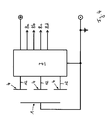
- a capacitive rotation angle sensor according to the invention is shown in a partial section.
- the rotation angle sensor comprises a first part 1 and a second part 2.
- the first part 1 is rotatable about an axis of rotation relative to the first part.
- the axis of rotation is formed by a shaft 3.
- the second part 2 is firmly installed in a housing 9.
- the first part 1 is formed as a fixed to the shaft 3 metallic eccentric.
- the shaft 3 is rotatably mounted with the eccentric as the first part 1 via a spacer 10 and a nut 11 in the housing 9.
- capacitor electrodes 4 of the illustrated embodiment cover an angular range of approximately 120 ° and are formed annularly around the axis of rotation or shaft 3.
- the capacitor electrodes 4 have substantially the same area and are designed in their shape almost identical, each in the form of a circular ring segment.
- the capacitor electrodes 4 are formed on a planar surface, which is formed by a circuit board 6, flat in a plane, and the eccentric has a capacitor electrodes 4 facing, substantially parallel to these aligned surface.
- the designed as an eccentric first part 1 covers during a rotational movement, the capacitor electrodes 4 at least partially.
- the first part 1 overlaps a portion of the capacitor electrodes 4 and forms an overlapping area that varies with the rotational movement of the first part 1.
- the configured as an eccentric attached to the shaft 3 first part 1 is located on a floating potential donor element for the capacitor electrodes 4, which means that the first part 1 is connected to any voltage source which impresses the first part 1, an electrical voltage. Instead, the first part 1 is connected to ground or electrically isolated from the environment.
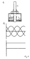
- Fig. 3 are the signals of the three capacitor electrodes 4 of the rotation angle sensor according to Fig. 1 shown.
- the signals are sinusoidal and shifted by 124 ° corresponding to a full revolution of 360 ° by the number of capacitor electrodes. Accordingly, the position of the eccentric on the capacitor electrodes 4 can be calculated back.
- the signals of the four equal-area capacitor electrodes 4 are shifted by 90 °.
- the distance of the first part 1 in the direction along the axis of rotation of the capacitor electrodes 4 is variable or changeable.
- the in Fig. 1 illustrated embodiment a spring 5, which biases the eccentric as a first part 1 relative to the second part 2, on which the capacitor electrodes 4 are formed. A pressure must be applied against the spring 5 so that the distance between the eccentric as the first part 1 and the capacitor electrodes 4 formed on the second part 2 decreases.
- a user operable handpiece fastened, with which the user can both rotate the shaft 3, and can exert tension or pressure on the shaft 3 in the direction along the shaft 3.
- latching elements may be provided to lock the eccentric at predetermined distances from the capacitor electrodes 4.
- each capacitor electrode 4 For evaluating the position of the first part 1 relative to the second part 2 formed with the capacitor electrodes 4, a tap line 12 is provided on each capacitor electrode 4, which connects the capacitor electrode 4 to an evaluation device 7 (cf. Fig. 4 ).
- the evaluation device 7 determines the charge quantity of each capacitor electrode 4 and generates at least one signal representative of the absolute position of the second part 2 to the first part 1.
- the comparison of the amount of charge on each capacitor electrode 4 can be made via a reference capacitor with a defined amount of charge.
- Fig. 4 shows a schematic diagram for an interconnection of the eccentric and the capacitor electrodes 4 with the evaluation device 7.
- At outputs 8a, 8b, 8c, 8d is at least one representative of the absolute position of the second part 2 to the first part 1 signal.
- Fig. 5a is the rotation angle sensor according to Fig. 1 shown schematically in a first position.
- Fig. 5b shows by way of example the signals generated by the evaluation device 7 at the outputs 8a, 8b and 8c from top to bottom.
- the signals applied to the outputs 8a and 8b indicate the absolute position of the eccentric relative to the three capacitor electrodes 4 relative to the direction of rotation about the axis of rotation or shaft 3.
- the signal at the output 8c is used to indicate the distance between the eccentric and the capacitor electrodes 4 along the axis of rotation.
- a summation element for adding up the charge quantities of the capacitor electrodes 4 used.
- the added charge amount of the capacitor electrodes 4 is compared with a comparison element for the determination of the distance between the eccentric and capacitor elements 4 and generates a corresponding signal at the output 8c.
- Fig. 6a the angle of rotation sensor is shown in a second position, in which the distance between the eccentric and the capacitor electrodes 4 has been reduced with respect to the in Fig. 5a shown position.
- Fig. 6b shows signals 8a, 8b and 8c generated by the evaluation device 7 at the time in Fig. 6a shown position. It can be seen that the signals at the outputs 8a and 8b have not changed, since the eccentric was not rotated, but only the distance between the eccentric and capacitor electrodes 4 has been changed. The sum of the charge quantities has changed. By reducing the distance of the eccentric from the capacitor electrodes 4, the sum of the amounts of charge on the capacitor electrodes 4 has become larger. The distance of the eccentric from the capacitor electrodes 4 can be determined absolutely on the basis of the signal applied to the output 8c.
- the angle (the rotary operation of the shaft 3) and the distance between the eccentric and capacitor electrodes 4 (the tensile or pressure actuation of the shaft 3) can be absolutely determined or measured.
- the evaluation device 7 may be designed as a microcontroller, which is arranged on the designed as a board 6 surface for the capacitor electrodes 4. According to Fig. 1 the board 6 forms a boundary surface of the housing 9 for the capacitive rotation angle sensor. On the capacitor electrodes 4th By using the circuit board 6 as a boundary surface of the housing 9 of the capacitive rotation angle sensor, a compact design is possible.
Landscapes
- Engineering & Computer Science (AREA)
- Power Engineering (AREA)
- Physics & Mathematics (AREA)
- General Physics & Mathematics (AREA)
- Transmission And Conversion Of Sensor Element Output (AREA)
- Measurement Of Length, Angles, Or The Like Using Electric Or Magnetic Means (AREA)
Claims (8)
- Capteur d'angle de rotation capacitif comprenant une première partie et une seconde partie (1, 2), parmi lesquelles la première partie (1) est mobile en rotation autour d'un arbre (3) comme axe de rotation par rapport à la seconde partie (2), et la seconde partie (2) comprend au moins trois électrodes de condensateur (4) tournées vers la première partie (1), isolées les unes des autres et distantes les unes des autres en direction du mouvement rotatif de l'axe de rotation, lesdites électrodes pouvant être amenées en chevauchement avec la première partie (1) au moins en partie les unes avec les autres et le chevauchement pouvant varier avec le mouvement rotatif, la première partie (1) étant un élément transmetteur placé à un potentiel flottant par rapport aux électrodes de condensateur (4) sous forme d'un excentrique métallique fixé à l'arbre, et les électrodes de condensateur (4) étant reliées respectivement par un lien de connexion (12) à un dispositif d'analyse (7) pour déterminer la charge de chaque électrode de condensateur (4), et le dispositif d'analyse (7) étant apte à produire un signal représentant la position absolue de la seconde partie (2) par rapport à la première partie (1), caractérisé en ce que l'écart entre l'excentrique et les électrodes de condensateur (4) peut varier le long de l'axe de rotation.
- Capteur d'angle de rotation capacitif selon la revendication 1, caractérisé en ce que la première partie (1) peut être enclenchée par rapport à la seconde partie (2) au moyen d'un dispositif d'enclenchement par différents intervalles prédéfinis par rapport à la direction le long de l'axe de rotation .
- Capteur d'angle de rotation capacitif selon la revendication 1 ou 2, caractérisé en ce que les électrodes de condensateur (4) sont formées à plat dans un plan sur une surface plane et l'excentrique présente une surface tournée vers les électrodes de condensateur (4) et orientée parallèlement auxdites électrodes.
- Capteur d'angle de rotation capacitif selon l'une des revendications 1 à 3, caractérisé en ce que les électrodes de condensateur (4) sont disposées au moins par parties en cercle autour de l'axe de rotation et présentent des superficies respectivement identiques.
- Capteur d'angle de rotation capacitif selon l'une des revendications 1 à 4, caractérisé en ce que la première partie (1) est précontrainte par un ressort par rapport à la seconde partie (2) par rapport à la direction s'étendant le long de l'axe de rotation.
- Capteur d'angle de rotation capacitif selon l'une des revendications 1 à 5, caractérisé en ce qu'un élément de sommation destiné à faire la somme des quantités de chargement des électrodes de condensateur (4) et un élément de comparaison pour la détermination de l'écart entre l'excentrique et les éléments de condensateur (4) sont prévus.
- Capteur d'angle de rotation capacitif selon l'une quelconque des revendications 1 à 6, caractérisé en ce que les électrodes de condensateur (4) sont disposées sur une platine (6) et des interfaces sont prévues sur le côté de la platine (6) opposé aux électrodes de condensateur (4) pour les conduites de raccordement (12) et/ou le dispositif d'analyse (7).
- Capteur d'angle de rotation capacitif selon l'une des revendications 1 à 7, caractérisé en ce que le dispositif d'analyse (7) est un microcontrôleur.
Priority Applications (1)
| Application Number | Priority Date | Filing Date | Title |
|---|---|---|---|
| EP08022133A EP2199751B1 (fr) | 2008-12-19 | 2008-12-19 | Capteur d'angle de rotation capacitif |
Applications Claiming Priority (1)
| Application Number | Priority Date | Filing Date | Title |
|---|---|---|---|
| EP08022133A EP2199751B1 (fr) | 2008-12-19 | 2008-12-19 | Capteur d'angle de rotation capacitif |
Publications (2)
| Publication Number | Publication Date |
|---|---|
| EP2199751A1 EP2199751A1 (fr) | 2010-06-23 |
| EP2199751B1 true EP2199751B1 (fr) | 2012-08-08 |
Family
ID=41376295
Family Applications (1)
| Application Number | Title | Priority Date | Filing Date |
|---|---|---|---|
| EP08022133A Not-in-force EP2199751B1 (fr) | 2008-12-19 | 2008-12-19 | Capteur d'angle de rotation capacitif |
Country Status (1)
| Country | Link |
|---|---|
| EP (1) | EP2199751B1 (fr) |
Family Cites Families (4)
| Publication number | Priority date | Publication date | Assignee | Title |
|---|---|---|---|---|
| DE3711062A1 (de) | 1987-04-02 | 1988-10-20 | Herbert Leypold | Kapazitive absolute positionsmessvorrichtung |
| DE4232116C2 (de) * | 1992-09-25 | 1999-03-18 | Mannesmann Vdo Ag | Anordnung für einen kapazitiven Drehwinkelsensor |
| US6492911B1 (en) * | 1999-04-19 | 2002-12-10 | Netzer Motion Sensors Ltd. | Capacitive displacement encoder |
| NL1018908C2 (nl) * | 2001-09-07 | 2003-03-11 | Skf Ab | Absolute-hoek-codeerinrichting. |
-
2008
- 2008-12-19 EP EP08022133A patent/EP2199751B1/fr not_active Not-in-force
Also Published As
| Publication number | Publication date |
|---|---|
| EP2199751A1 (fr) | 2010-06-23 |
Similar Documents
| Publication | Publication Date | Title |
|---|---|---|
| EP2782810B1 (fr) | Capteur d'angle de rotation | |
| DE60222356T2 (de) | Drehwinkelsensor, Drehmomentsensor und Lenkvorrichtung | |
| DE102008008835B4 (de) | Vorrichtung zum Ermitteln eines Drehmoments | |
| EP1081454B1 (fr) | Capteur de position inductif | |
| DE102014208642B4 (de) | Sensoranordnung zur Erfassung von Drehwinkeln an einem rotierenden Bauteil in einem Fahrzeug | |
| EP2225142B1 (fr) | Arrangement de detection de l'angle de direction a mesure absolue | |
| EP2026366B1 (fr) | Sélecteur rotatif | |
| DE102013224098A1 (de) | Sensoranordnung zur Erfassung von Drehwinkeln an einem rotierenden Bauteil in einem Fahrzeug | |
| DE102007014751A1 (de) | Potentiometer | |
| EP2449346A2 (fr) | Capteur angulaire | |
| DE102009027191A1 (de) | Vorrichtung zum Bestimmen eines Drehmomentes und/oder eines Drehwinkels einer Welle | |
| EP1925533B1 (fr) | Capteur d'angle de rotation et de couple combiné | |
| DE102018120575A1 (de) | Eingabevorrichtung mit beweglicher Handhabe auf kapazitiver Detektionsfläche und kapazitiven Koppeleinrichtungen | |
| DE102019214219A1 (de) | Messeinrichtung | |
| WO2016180411A1 (fr) | Ensemble capteur comprenant un capteur angulaire et ensemble palier à roulement comprenant un ensemble capteur | |
| DE4234016A1 (de) | Kapazitiv arbeitende positionsmessvorrichtung | |
| DE102019122188A1 (de) | Winkelsensorsystem | |
| WO2007065496A1 (fr) | Detecteur d'angle de rotation et système de detection de l'angle de rotation | |
| DE19800774B4 (de) | Verfahren und magnetische Maßverkörperung zur Generierung eines Referenzsignals sowie Herstellungsverfahren für eine solche magnetische Maßverkörperung | |
| DE10348914B4 (de) | Vorrichtung zum Messen des Drehwinkels eines Drehkörpers | |
| EP2199751B1 (fr) | Capteur d'angle de rotation capacitif | |
| DE102007010737A1 (de) | Vorrichtung zur Erfassung des absoluten Drehwinkels einer Welle | |
| EP3427010A1 (fr) | Capteur de déplacement tolérant au basculement | |
| DE102005035107A1 (de) | Mess- bzw. Gebervorrichtung | |
| DE4125482C2 (fr) |
Legal Events
| Date | Code | Title | Description |
|---|---|---|---|
| PUAI | Public reference made under article 153(3) epc to a published international application that has entered the european phase |
Free format text: ORIGINAL CODE: 0009012 |
|
| AK | Designated contracting states |
Kind code of ref document: A1 Designated state(s): AT BE BG CH CY CZ DE DK EE ES FI FR GB GR HR HU IE IS IT LI LT LU LV MC MT NL NO PL PT RO SE SI SK TR |
|
| AX | Request for extension of the european patent |
Extension state: AL BA MK RS |
|
| 17P | Request for examination filed |
Effective date: 20101220 |
|
| AKX | Designation fees paid |
Designated state(s): DE FR GB IT |
|
| GRAP | Despatch of communication of intention to grant a patent |
Free format text: ORIGINAL CODE: EPIDOSNIGR1 |
|
| RIC1 | Information provided on ipc code assigned before grant |
Ipc: G01D 5/241 20060101AFI20120207BHEP |
|
| GRAS | Grant fee paid |
Free format text: ORIGINAL CODE: EPIDOSNIGR3 |
|
| GRAA | (expected) grant |
Free format text: ORIGINAL CODE: 0009210 |
|
| AK | Designated contracting states |
Kind code of ref document: B1 Designated state(s): DE FR GB IT |
|
| REG | Reference to a national code |
Ref country code: GB Ref legal event code: FG4D Free format text: NOT ENGLISH |
|
| REG | Reference to a national code |
Ref country code: DE Ref legal event code: R096 Ref document number: 502008007871 Country of ref document: DE Effective date: 20121004 |
|
| PG25 | Lapsed in a contracting state [announced via postgrant information from national office to epo] |
Ref country code: IT Free format text: LAPSE BECAUSE OF FAILURE TO SUBMIT A TRANSLATION OF THE DESCRIPTION OR TO PAY THE FEE WITHIN THE PRESCRIBED TIME-LIMIT Effective date: 20120808 |
|
| PLBE | No opposition filed within time limit |
Free format text: ORIGINAL CODE: 0009261 |
|
| STAA | Information on the status of an ep patent application or granted ep patent |
Free format text: STATUS: NO OPPOSITION FILED WITHIN TIME LIMIT |
|
| 26N | No opposition filed |
Effective date: 20130510 |
|
| GBPC | Gb: european patent ceased through non-payment of renewal fee |
Effective date: 20121219 |
|
| REG | Reference to a national code |
Ref country code: DE Ref legal event code: R097 Ref document number: 502008007871 Country of ref document: DE Effective date: 20130510 |
|
| REG | Reference to a national code |
Ref country code: FR Ref legal event code: ST Effective date: 20130830 |
|
| PG25 | Lapsed in a contracting state [announced via postgrant information from national office to epo] |
Ref country code: GB Free format text: LAPSE BECAUSE OF NON-PAYMENT OF DUE FEES Effective date: 20121219 Ref country code: FR Free format text: LAPSE BECAUSE OF NON-PAYMENT OF DUE FEES Effective date: 20130102 |
|
| REG | Reference to a national code |
Ref country code: DE Ref legal event code: R082 Ref document number: 502008007871 Country of ref document: DE |
|
| REG | Reference to a national code |
Ref country code: DE Ref legal event code: R081 Ref document number: 502008007871 Country of ref document: DE Owner name: TUEBLUEKER, HUESEYIN, DE Free format text: FORMER OWNER: MENTOR GMBH & CO PRAEZISIONS-BAUTEILE KG, 40699 ERKRATH, DE Effective date: 20140225 |
|
| PGFP | Annual fee paid to national office [announced via postgrant information from national office to epo] |
Ref country code: DE Payment date: 20180625 Year of fee payment: 10 |
|
| REG | Reference to a national code |
Ref country code: DE Ref legal event code: R119 Ref document number: 502008007871 Country of ref document: DE |
|
| PG25 | Lapsed in a contracting state [announced via postgrant information from national office to epo] |
Ref country code: DE Free format text: LAPSE BECAUSE OF NON-PAYMENT OF DUE FEES Effective date: 20190702 |