EP2199716A2 - Alternative Vorkühlungsanordnung - Google Patents
Alternative Vorkühlungsanordnung Download PDFInfo
- Publication number
- EP2199716A2 EP2199716A2 EP09178825A EP09178825A EP2199716A2 EP 2199716 A2 EP2199716 A2 EP 2199716A2 EP 09178825 A EP09178825 A EP 09178825A EP 09178825 A EP09178825 A EP 09178825A EP 2199716 A2 EP2199716 A2 EP 2199716A2
- Authority
- EP
- European Patent Office
- Prior art keywords
- stream
- precooling
- refrigeration system
- refrigerant
- compressor
- Prior art date
- Legal status (The legal status is an assumption and is not a legal conclusion. Google has not performed a legal analysis and makes no representation as to the accuracy of the status listed.)
- Withdrawn
Links
- 238000001816 cooling Methods 0.000 title description 36
- 239000003507 refrigerant Substances 0.000 claims abstract description 203
- VNWKTOKETHGBQD-UHFFFAOYSA-N methane Chemical compound C VNWKTOKETHGBQD-UHFFFAOYSA-N 0.000 claims abstract description 162
- 238000005057 refrigeration Methods 0.000 claims abstract description 126
- 239000003345 natural gas Substances 0.000 claims abstract description 77
- ATUOYWHBWRKTHZ-UHFFFAOYSA-N Propane Chemical group CCC ATUOYWHBWRKTHZ-UHFFFAOYSA-N 0.000 claims description 188
- 239000001294 propane Substances 0.000 claims description 94
- 239000007789 gas Substances 0.000 claims description 50
- 238000000034 method Methods 0.000 claims description 34
- 230000008016 vaporization Effects 0.000 claims description 16
- 239000012530 fluid Substances 0.000 claims description 8
- 239000007788 liquid Substances 0.000 description 23
- 239000003949 liquefied natural gas Substances 0.000 description 18
- 238000001704 evaporation Methods 0.000 description 14
- 230000008020 evaporation Effects 0.000 description 14
- 239000007858 starting material Substances 0.000 description 8
- CURLTUGMZLYLDI-UHFFFAOYSA-N Carbon dioxide Chemical compound O=C=O CURLTUGMZLYLDI-UHFFFAOYSA-N 0.000 description 7
- IJGRMHOSHXDMSA-UHFFFAOYSA-N Atomic nitrogen Chemical compound N#N IJGRMHOSHXDMSA-UHFFFAOYSA-N 0.000 description 6
- 239000001569 carbon dioxide Substances 0.000 description 5
- 229910002092 carbon dioxide Inorganic materials 0.000 description 5
- 230000006835 compression Effects 0.000 description 5
- 238000007906 compression Methods 0.000 description 5
- OTMSDBZUPAUEDD-UHFFFAOYSA-N Ethane Chemical compound CC OTMSDBZUPAUEDD-UHFFFAOYSA-N 0.000 description 4
- RAHZWNYVWXNFOC-UHFFFAOYSA-N Sulphur dioxide Chemical compound O=S=O RAHZWNYVWXNFOC-UHFFFAOYSA-N 0.000 description 4
- NNPPMTNAJDCUHE-UHFFFAOYSA-N isobutane Chemical compound CC(C)C NNPPMTNAJDCUHE-UHFFFAOYSA-N 0.000 description 4
- 238000013341 scale-up Methods 0.000 description 4
- 238000004088 simulation Methods 0.000 description 4
- 238000009834 vaporization Methods 0.000 description 4
- 238000010792 warming Methods 0.000 description 4
- UHOVQNZJYSORNB-UHFFFAOYSA-N Benzene Chemical compound C1=CC=CC=C1 UHOVQNZJYSORNB-UHFFFAOYSA-N 0.000 description 3
- YXFVVABEGXRONW-UHFFFAOYSA-N Toluene Chemical compound CC1=CC=CC=C1 YXFVVABEGXRONW-UHFFFAOYSA-N 0.000 description 3
- 229910052757 nitrogen Inorganic materials 0.000 description 3
- XLYOFNOQVPJJNP-UHFFFAOYSA-N water Substances O XLYOFNOQVPJJNP-UHFFFAOYSA-N 0.000 description 3
- VGGSQFUCUMXWEO-UHFFFAOYSA-N Ethene Chemical compound C=C VGGSQFUCUMXWEO-UHFFFAOYSA-N 0.000 description 2
- YNQLUTRBYVCPMQ-UHFFFAOYSA-N Ethylbenzene Chemical compound CCC1=CC=CC=C1 YNQLUTRBYVCPMQ-UHFFFAOYSA-N 0.000 description 2
- 239000005977 Ethylene Substances 0.000 description 2
- 238000005094 computer simulation Methods 0.000 description 2
- 239000001282 iso-butane Substances 0.000 description 2
- 235000013847 iso-butane Nutrition 0.000 description 2
- QWTDNUCVQCZILF-UHFFFAOYSA-N isopentane Chemical compound CCC(C)C QWTDNUCVQCZILF-UHFFFAOYSA-N 0.000 description 2
- 238000004519 manufacturing process Methods 0.000 description 2
- IJDNQMDRQITEOD-UHFFFAOYSA-N n-butane Chemical compound CCCC IJDNQMDRQITEOD-UHFFFAOYSA-N 0.000 description 2
- QQONPFPTGQHPMA-UHFFFAOYSA-N propylene Natural products CC=C QQONPFPTGQHPMA-UHFFFAOYSA-N 0.000 description 2
- 125000004805 propylene group Chemical group [H]C([H])([H])C([H])([*:1])C([H])([H])[*:2] 0.000 description 2
- VOPWNXZWBYDODV-UHFFFAOYSA-N Chlorodifluoromethane Chemical compound FC(F)Cl VOPWNXZWBYDODV-UHFFFAOYSA-N 0.000 description 1
- XAGFODPZIPBFFR-UHFFFAOYSA-N aluminium Chemical compound [Al] XAGFODPZIPBFFR-UHFFFAOYSA-N 0.000 description 1
- 229910052782 aluminium Inorganic materials 0.000 description 1
- 239000001273 butane Substances 0.000 description 1
- 238000004364 calculation method Methods 0.000 description 1
- 238000010276 construction Methods 0.000 description 1
- AFABGHUZZDYHJO-UHFFFAOYSA-N dimethyl butane Natural products CCCC(C)C AFABGHUZZDYHJO-UHFFFAOYSA-N 0.000 description 1
- ILEDWLMCKZNDJK-UHFFFAOYSA-N esculetin Chemical compound C1=CC(=O)OC2=C1C=C(O)C(O)=C2 ILEDWLMCKZNDJK-UHFFFAOYSA-N 0.000 description 1
- 230000002349 favourable effect Effects 0.000 description 1
- 230000008014 freezing Effects 0.000 description 1
- 238000007710 freezing Methods 0.000 description 1
- 238000012423 maintenance Methods 0.000 description 1
- QSHDDOUJBYECFT-UHFFFAOYSA-N mercury Chemical compound [Hg] QSHDDOUJBYECFT-UHFFFAOYSA-N 0.000 description 1
- 229910052753 mercury Inorganic materials 0.000 description 1
- OFBQJSOFQDEBGM-UHFFFAOYSA-N n-pentane Natural products CCCCC OFBQJSOFQDEBGM-UHFFFAOYSA-N 0.000 description 1
- 238000004513 sizing Methods 0.000 description 1
Images


Classifications
-
- F—MECHANICAL ENGINEERING; LIGHTING; HEATING; WEAPONS; BLASTING
- F25—REFRIGERATION OR COOLING; COMBINED HEATING AND REFRIGERATION SYSTEMS; HEAT PUMP SYSTEMS; MANUFACTURE OR STORAGE OF ICE; LIQUEFACTION SOLIDIFICATION OF GASES
- F25J—LIQUEFACTION, SOLIDIFICATION OR SEPARATION OF GASES OR GASEOUS OR LIQUEFIED GASEOUS MIXTURES BY PRESSURE AND COLD TREATMENT OR BY BRINGING THEM INTO THE SUPERCRITICAL STATE
- F25J3/00—Processes or apparatus for separating the constituents of gaseous or liquefied gaseous mixtures involving the use of liquefaction or solidification
-
- F—MECHANICAL ENGINEERING; LIGHTING; HEATING; WEAPONS; BLASTING
- F25—REFRIGERATION OR COOLING; COMBINED HEATING AND REFRIGERATION SYSTEMS; HEAT PUMP SYSTEMS; MANUFACTURE OR STORAGE OF ICE; LIQUEFACTION SOLIDIFICATION OF GASES
- F25J—LIQUEFACTION, SOLIDIFICATION OR SEPARATION OF GASES OR GASEOUS OR LIQUEFIED GASEOUS MIXTURES BY PRESSURE AND COLD TREATMENT OR BY BRINGING THEM INTO THE SUPERCRITICAL STATE
- F25J1/00—Processes or apparatus for liquefying or solidifying gases or gaseous mixtures
- F25J1/02—Processes or apparatus for liquefying or solidifying gases or gaseous mixtures requiring the use of refrigeration, e.g. of helium or hydrogen ; Details and kind of the refrigeration system used; Integration with other units or processes; Controlling aspects of the process
- F25J1/0211—Processes or apparatus for liquefying or solidifying gases or gaseous mixtures requiring the use of refrigeration, e.g. of helium or hydrogen ; Details and kind of the refrigeration system used; Integration with other units or processes; Controlling aspects of the process using a multi-component refrigerant [MCR] fluid in a closed vapor compression cycle
- F25J1/0214—Processes or apparatus for liquefying or solidifying gases or gaseous mixtures requiring the use of refrigeration, e.g. of helium or hydrogen ; Details and kind of the refrigeration system used; Integration with other units or processes; Controlling aspects of the process using a multi-component refrigerant [MCR] fluid in a closed vapor compression cycle as a dual level refrigeration cascade with at least one MCR cycle
- F25J1/0215—Processes or apparatus for liquefying or solidifying gases or gaseous mixtures requiring the use of refrigeration, e.g. of helium or hydrogen ; Details and kind of the refrigeration system used; Integration with other units or processes; Controlling aspects of the process using a multi-component refrigerant [MCR] fluid in a closed vapor compression cycle as a dual level refrigeration cascade with at least one MCR cycle with one SCR cycle
- F25J1/0216—Processes or apparatus for liquefying or solidifying gases or gaseous mixtures requiring the use of refrigeration, e.g. of helium or hydrogen ; Details and kind of the refrigeration system used; Integration with other units or processes; Controlling aspects of the process using a multi-component refrigerant [MCR] fluid in a closed vapor compression cycle as a dual level refrigeration cascade with at least one MCR cycle with one SCR cycle using a C3 pre-cooling cycle
-
- F—MECHANICAL ENGINEERING; LIGHTING; HEATING; WEAPONS; BLASTING
- F25—REFRIGERATION OR COOLING; COMBINED HEATING AND REFRIGERATION SYSTEMS; HEAT PUMP SYSTEMS; MANUFACTURE OR STORAGE OF ICE; LIQUEFACTION SOLIDIFICATION OF GASES
- F25J—LIQUEFACTION, SOLIDIFICATION OR SEPARATION OF GASES OR GASEOUS OR LIQUEFIED GASEOUS MIXTURES BY PRESSURE AND COLD TREATMENT OR BY BRINGING THEM INTO THE SUPERCRITICAL STATE
- F25J1/00—Processes or apparatus for liquefying or solidifying gases or gaseous mixtures
- F25J1/0002—Processes or apparatus for liquefying or solidifying gases or gaseous mixtures characterised by the fluid to be liquefied
- F25J1/0022—Hydrocarbons, e.g. natural gas
-
- F—MECHANICAL ENGINEERING; LIGHTING; HEATING; WEAPONS; BLASTING
- F25—REFRIGERATION OR COOLING; COMBINED HEATING AND REFRIGERATION SYSTEMS; HEAT PUMP SYSTEMS; MANUFACTURE OR STORAGE OF ICE; LIQUEFACTION SOLIDIFICATION OF GASES
- F25J—LIQUEFACTION, SOLIDIFICATION OR SEPARATION OF GASES OR GASEOUS OR LIQUEFIED GASEOUS MIXTURES BY PRESSURE AND COLD TREATMENT OR BY BRINGING THEM INTO THE SUPERCRITICAL STATE
- F25J1/00—Processes or apparatus for liquefying or solidifying gases or gaseous mixtures
- F25J1/003—Processes or apparatus for liquefying or solidifying gases or gaseous mixtures characterised by the kind of cold generation within the liquefaction unit for compensating heat leaks and liquid production
- F25J1/0047—Processes or apparatus for liquefying or solidifying gases or gaseous mixtures characterised by the kind of cold generation within the liquefaction unit for compensating heat leaks and liquid production using an "external" refrigerant stream in a closed vapor compression cycle
- F25J1/0052—Processes or apparatus for liquefying or solidifying gases or gaseous mixtures characterised by the kind of cold generation within the liquefaction unit for compensating heat leaks and liquid production using an "external" refrigerant stream in a closed vapor compression cycle by vaporising a liquid refrigerant stream
- F25J1/0055—Processes or apparatus for liquefying or solidifying gases or gaseous mixtures characterised by the kind of cold generation within the liquefaction unit for compensating heat leaks and liquid production using an "external" refrigerant stream in a closed vapor compression cycle by vaporising a liquid refrigerant stream originating from an incorporated cascade
-
- F—MECHANICAL ENGINEERING; LIGHTING; HEATING; WEAPONS; BLASTING
- F25—REFRIGERATION OR COOLING; COMBINED HEATING AND REFRIGERATION SYSTEMS; HEAT PUMP SYSTEMS; MANUFACTURE OR STORAGE OF ICE; LIQUEFACTION SOLIDIFICATION OF GASES
- F25J—LIQUEFACTION, SOLIDIFICATION OR SEPARATION OF GASES OR GASEOUS OR LIQUEFIED GASEOUS MIXTURES BY PRESSURE AND COLD TREATMENT OR BY BRINGING THEM INTO THE SUPERCRITICAL STATE
- F25J1/00—Processes or apparatus for liquefying or solidifying gases or gaseous mixtures
- F25J1/006—Processes or apparatus for liquefying or solidifying gases or gaseous mixtures characterised by the refrigerant fluid used
- F25J1/008—Hydrocarbons
- F25J1/0082—Methane
-
- F—MECHANICAL ENGINEERING; LIGHTING; HEATING; WEAPONS; BLASTING
- F25—REFRIGERATION OR COOLING; COMBINED HEATING AND REFRIGERATION SYSTEMS; HEAT PUMP SYSTEMS; MANUFACTURE OR STORAGE OF ICE; LIQUEFACTION SOLIDIFICATION OF GASES
- F25J—LIQUEFACTION, SOLIDIFICATION OR SEPARATION OF GASES OR GASEOUS OR LIQUEFIED GASEOUS MIXTURES BY PRESSURE AND COLD TREATMENT OR BY BRINGING THEM INTO THE SUPERCRITICAL STATE
- F25J1/00—Processes or apparatus for liquefying or solidifying gases or gaseous mixtures
- F25J1/006—Processes or apparatus for liquefying or solidifying gases or gaseous mixtures characterised by the refrigerant fluid used
- F25J1/008—Hydrocarbons
- F25J1/0085—Ethane; Ethylene
-
- F—MECHANICAL ENGINEERING; LIGHTING; HEATING; WEAPONS; BLASTING
- F25—REFRIGERATION OR COOLING; COMBINED HEATING AND REFRIGERATION SYSTEMS; HEAT PUMP SYSTEMS; MANUFACTURE OR STORAGE OF ICE; LIQUEFACTION SOLIDIFICATION OF GASES
- F25J—LIQUEFACTION, SOLIDIFICATION OR SEPARATION OF GASES OR GASEOUS OR LIQUEFIED GASEOUS MIXTURES BY PRESSURE AND COLD TREATMENT OR BY BRINGING THEM INTO THE SUPERCRITICAL STATE
- F25J1/00—Processes or apparatus for liquefying or solidifying gases or gaseous mixtures
- F25J1/006—Processes or apparatus for liquefying or solidifying gases or gaseous mixtures characterised by the refrigerant fluid used
- F25J1/008—Hydrocarbons
- F25J1/0087—Propane; Propylene
-
- F—MECHANICAL ENGINEERING; LIGHTING; HEATING; WEAPONS; BLASTING
- F25—REFRIGERATION OR COOLING; COMBINED HEATING AND REFRIGERATION SYSTEMS; HEAT PUMP SYSTEMS; MANUFACTURE OR STORAGE OF ICE; LIQUEFACTION SOLIDIFICATION OF GASES
- F25J—LIQUEFACTION, SOLIDIFICATION OR SEPARATION OF GASES OR GASEOUS OR LIQUEFIED GASEOUS MIXTURES BY PRESSURE AND COLD TREATMENT OR BY BRINGING THEM INTO THE SUPERCRITICAL STATE
- F25J1/00—Processes or apparatus for liquefying or solidifying gases or gaseous mixtures
- F25J1/006—Processes or apparatus for liquefying or solidifying gases or gaseous mixtures characterised by the refrigerant fluid used
- F25J1/0095—Oxides of carbon, e.g. CO2
-
- F—MECHANICAL ENGINEERING; LIGHTING; HEATING; WEAPONS; BLASTING
- F25—REFRIGERATION OR COOLING; COMBINED HEATING AND REFRIGERATION SYSTEMS; HEAT PUMP SYSTEMS; MANUFACTURE OR STORAGE OF ICE; LIQUEFACTION SOLIDIFICATION OF GASES
- F25J—LIQUEFACTION, SOLIDIFICATION OR SEPARATION OF GASES OR GASEOUS OR LIQUEFIED GASEOUS MIXTURES BY PRESSURE AND COLD TREATMENT OR BY BRINGING THEM INTO THE SUPERCRITICAL STATE
- F25J1/00—Processes or apparatus for liquefying or solidifying gases or gaseous mixtures
- F25J1/006—Processes or apparatus for liquefying or solidifying gases or gaseous mixtures characterised by the refrigerant fluid used
- F25J1/0097—Others, e.g. F-, Cl-, HF-, HClF-, HCl-hydrocarbons etc. or mixtures thereof
-
- F—MECHANICAL ENGINEERING; LIGHTING; HEATING; WEAPONS; BLASTING
- F25—REFRIGERATION OR COOLING; COMBINED HEATING AND REFRIGERATION SYSTEMS; HEAT PUMP SYSTEMS; MANUFACTURE OR STORAGE OF ICE; LIQUEFACTION SOLIDIFICATION OF GASES
- F25J—LIQUEFACTION, SOLIDIFICATION OR SEPARATION OF GASES OR GASEOUS OR LIQUEFIED GASEOUS MIXTURES BY PRESSURE AND COLD TREATMENT OR BY BRINGING THEM INTO THE SUPERCRITICAL STATE
- F25J1/00—Processes or apparatus for liquefying or solidifying gases or gaseous mixtures
- F25J1/02—Processes or apparatus for liquefying or solidifying gases or gaseous mixtures requiring the use of refrigeration, e.g. of helium or hydrogen ; Details and kind of the refrigeration system used; Integration with other units or processes; Controlling aspects of the process
- F25J1/0211—Processes or apparatus for liquefying or solidifying gases or gaseous mixtures requiring the use of refrigeration, e.g. of helium or hydrogen ; Details and kind of the refrigeration system used; Integration with other units or processes; Controlling aspects of the process using a multi-component refrigerant [MCR] fluid in a closed vapor compression cycle
- F25J1/0217—Processes or apparatus for liquefying or solidifying gases or gaseous mixtures requiring the use of refrigeration, e.g. of helium or hydrogen ; Details and kind of the refrigeration system used; Integration with other units or processes; Controlling aspects of the process using a multi-component refrigerant [MCR] fluid in a closed vapor compression cycle as at least a three level refrigeration cascade with at least one MCR cycle
- F25J1/0218—Processes or apparatus for liquefying or solidifying gases or gaseous mixtures requiring the use of refrigeration, e.g. of helium or hydrogen ; Details and kind of the refrigeration system used; Integration with other units or processes; Controlling aspects of the process using a multi-component refrigerant [MCR] fluid in a closed vapor compression cycle as at least a three level refrigeration cascade with at least one MCR cycle with one or more SCR cycles, e.g. with a C3 pre-cooling cycle
-
- F—MECHANICAL ENGINEERING; LIGHTING; HEATING; WEAPONS; BLASTING
- F25—REFRIGERATION OR COOLING; COMBINED HEATING AND REFRIGERATION SYSTEMS; HEAT PUMP SYSTEMS; MANUFACTURE OR STORAGE OF ICE; LIQUEFACTION SOLIDIFICATION OF GASES
- F25J—LIQUEFACTION, SOLIDIFICATION OR SEPARATION OF GASES OR GASEOUS OR LIQUEFIED GASEOUS MIXTURES BY PRESSURE AND COLD TREATMENT OR BY BRINGING THEM INTO THE SUPERCRITICAL STATE
- F25J1/00—Processes or apparatus for liquefying or solidifying gases or gaseous mixtures
- F25J1/02—Processes or apparatus for liquefying or solidifying gases or gaseous mixtures requiring the use of refrigeration, e.g. of helium or hydrogen ; Details and kind of the refrigeration system used; Integration with other units or processes; Controlling aspects of the process
- F25J1/0243—Start-up or control of the process; Details of the apparatus used; Details of the refrigerant compression system used
- F25J1/0257—Construction and layout of liquefaction equipments, e.g. valves, machines
- F25J1/0262—Details of the cold heat exchange system
- F25J1/0264—Arrangement of heat exchanger cores in parallel with different functions, e.g. different cooling streams
- F25J1/0265—Arrangement of heat exchanger cores in parallel with different functions, e.g. different cooling streams comprising cores associated exclusively with the cooling of a refrigerant stream, e.g. for auto-refrigeration or economizer
- F25J1/0268—Arrangement of heat exchanger cores in parallel with different functions, e.g. different cooling streams comprising cores associated exclusively with the cooling of a refrigerant stream, e.g. for auto-refrigeration or economizer using a dedicated refrigeration means
-
- F—MECHANICAL ENGINEERING; LIGHTING; HEATING; WEAPONS; BLASTING
- F25—REFRIGERATION OR COOLING; COMBINED HEATING AND REFRIGERATION SYSTEMS; HEAT PUMP SYSTEMS; MANUFACTURE OR STORAGE OF ICE; LIQUEFACTION SOLIDIFICATION OF GASES
- F25J—LIQUEFACTION, SOLIDIFICATION OR SEPARATION OF GASES OR GASEOUS OR LIQUEFIED GASEOUS MIXTURES BY PRESSURE AND COLD TREATMENT OR BY BRINGING THEM INTO THE SUPERCRITICAL STATE
- F25J1/00—Processes or apparatus for liquefying or solidifying gases or gaseous mixtures
- F25J1/02—Processes or apparatus for liquefying or solidifying gases or gaseous mixtures requiring the use of refrigeration, e.g. of helium or hydrogen ; Details and kind of the refrigeration system used; Integration with other units or processes; Controlling aspects of the process
- F25J1/0243—Start-up or control of the process; Details of the apparatus used; Details of the refrigerant compression system used
- F25J1/0279—Compression of refrigerant or internal recycle fluid, e.g. kind of compressor, accumulator, suction drum etc.
- F25J1/0281—Compression of refrigerant or internal recycle fluid, e.g. kind of compressor, accumulator, suction drum etc. characterised by the type of prime driver, e.g. hot gas expander
- F25J1/0283—Gas turbine as the prime mechanical driver
-
- F—MECHANICAL ENGINEERING; LIGHTING; HEATING; WEAPONS; BLASTING
- F25—REFRIGERATION OR COOLING; COMBINED HEATING AND REFRIGERATION SYSTEMS; HEAT PUMP SYSTEMS; MANUFACTURE OR STORAGE OF ICE; LIQUEFACTION SOLIDIFICATION OF GASES
- F25J—LIQUEFACTION, SOLIDIFICATION OR SEPARATION OF GASES OR GASEOUS OR LIQUEFIED GASEOUS MIXTURES BY PRESSURE AND COLD TREATMENT OR BY BRINGING THEM INTO THE SUPERCRITICAL STATE
- F25J1/00—Processes or apparatus for liquefying or solidifying gases or gaseous mixtures
- F25J1/02—Processes or apparatus for liquefying or solidifying gases or gaseous mixtures requiring the use of refrigeration, e.g. of helium or hydrogen ; Details and kind of the refrigeration system used; Integration with other units or processes; Controlling aspects of the process
- F25J1/0243—Start-up or control of the process; Details of the apparatus used; Details of the refrigerant compression system used
- F25J1/0279—Compression of refrigerant or internal recycle fluid, e.g. kind of compressor, accumulator, suction drum etc.
- F25J1/0285—Combination of different types of drivers mechanically coupled to the same refrigerant compressor, possibly split on multiple compressor casings
- F25J1/0287—Combination of different types of drivers mechanically coupled to the same refrigerant compressor, possibly split on multiple compressor casings including an electrical motor
-
- F—MECHANICAL ENGINEERING; LIGHTING; HEATING; WEAPONS; BLASTING
- F25—REFRIGERATION OR COOLING; COMBINED HEATING AND REFRIGERATION SYSTEMS; HEAT PUMP SYSTEMS; MANUFACTURE OR STORAGE OF ICE; LIQUEFACTION SOLIDIFICATION OF GASES
- F25J—LIQUEFACTION, SOLIDIFICATION OR SEPARATION OF GASES OR GASEOUS OR LIQUEFIED GASEOUS MIXTURES BY PRESSURE AND COLD TREATMENT OR BY BRINGING THEM INTO THE SUPERCRITICAL STATE
- F25J1/00—Processes or apparatus for liquefying or solidifying gases or gaseous mixtures
- F25J1/02—Processes or apparatus for liquefying or solidifying gases or gaseous mixtures requiring the use of refrigeration, e.g. of helium or hydrogen ; Details and kind of the refrigeration system used; Integration with other units or processes; Controlling aspects of the process
- F25J1/0243—Start-up or control of the process; Details of the apparatus used; Details of the refrigerant compression system used
- F25J1/0279—Compression of refrigerant or internal recycle fluid, e.g. kind of compressor, accumulator, suction drum etc.
- F25J1/029—Mechanically coupling of different refrigerant compressors in a cascade refrigeration system to a common driver
-
- F—MECHANICAL ENGINEERING; LIGHTING; HEATING; WEAPONS; BLASTING
- F25—REFRIGERATION OR COOLING; COMBINED HEATING AND REFRIGERATION SYSTEMS; HEAT PUMP SYSTEMS; MANUFACTURE OR STORAGE OF ICE; LIQUEFACTION SOLIDIFICATION OF GASES
- F25J—LIQUEFACTION, SOLIDIFICATION OR SEPARATION OF GASES OR GASEOUS OR LIQUEFIED GASEOUS MIXTURES BY PRESSURE AND COLD TREATMENT OR BY BRINGING THEM INTO THE SUPERCRITICAL STATE
- F25J1/00—Processes or apparatus for liquefying or solidifying gases or gaseous mixtures
- F25J1/02—Processes or apparatus for liquefying or solidifying gases or gaseous mixtures requiring the use of refrigeration, e.g. of helium or hydrogen ; Details and kind of the refrigeration system used; Integration with other units or processes; Controlling aspects of the process
- F25J1/0243—Start-up or control of the process; Details of the apparatus used; Details of the refrigerant compression system used
- F25J1/0279—Compression of refrigerant or internal recycle fluid, e.g. kind of compressor, accumulator, suction drum etc.
- F25J1/0292—Refrigerant compression by cold or cryogenic suction of the refrigerant gas
-
- F—MECHANICAL ENGINEERING; LIGHTING; HEATING; WEAPONS; BLASTING
- F25—REFRIGERATION OR COOLING; COMBINED HEATING AND REFRIGERATION SYSTEMS; HEAT PUMP SYSTEMS; MANUFACTURE OR STORAGE OF ICE; LIQUEFACTION SOLIDIFICATION OF GASES
- F25J—LIQUEFACTION, SOLIDIFICATION OR SEPARATION OF GASES OR GASEOUS OR LIQUEFIED GASEOUS MIXTURES BY PRESSURE AND COLD TREATMENT OR BY BRINGING THEM INTO THE SUPERCRITICAL STATE
- F25J1/00—Processes or apparatus for liquefying or solidifying gases or gaseous mixtures
- F25J1/02—Processes or apparatus for liquefying or solidifying gases or gaseous mixtures requiring the use of refrigeration, e.g. of helium or hydrogen ; Details and kind of the refrigeration system used; Integration with other units or processes; Controlling aspects of the process
- F25J1/0243—Start-up or control of the process; Details of the apparatus used; Details of the refrigerant compression system used
- F25J1/0279—Compression of refrigerant or internal recycle fluid, e.g. kind of compressor, accumulator, suction drum etc.
- F25J1/0295—Shifting of the compression load between different cooling stages within a refrigerant cycle or within a cascade refrigeration system
-
- F—MECHANICAL ENGINEERING; LIGHTING; HEATING; WEAPONS; BLASTING
- F25—REFRIGERATION OR COOLING; COMBINED HEATING AND REFRIGERATION SYSTEMS; HEAT PUMP SYSTEMS; MANUFACTURE OR STORAGE OF ICE; LIQUEFACTION SOLIDIFICATION OF GASES
- F25J—LIQUEFACTION, SOLIDIFICATION OR SEPARATION OF GASES OR GASEOUS OR LIQUEFIED GASEOUS MIXTURES BY PRESSURE AND COLD TREATMENT OR BY BRINGING THEM INTO THE SUPERCRITICAL STATE
- F25J5/00—Arrangements of cold exchangers or cold accumulators in separation or liquefaction plants
-
- F—MECHANICAL ENGINEERING; LIGHTING; HEATING; WEAPONS; BLASTING
- F25—REFRIGERATION OR COOLING; COMBINED HEATING AND REFRIGERATION SYSTEMS; HEAT PUMP SYSTEMS; MANUFACTURE OR STORAGE OF ICE; LIQUEFACTION SOLIDIFICATION OF GASES
- F25J—LIQUEFACTION, SOLIDIFICATION OR SEPARATION OF GASES OR GASEOUS OR LIQUEFIED GASEOUS MIXTURES BY PRESSURE AND COLD TREATMENT OR BY BRINGING THEM INTO THE SUPERCRITICAL STATE
- F25J2270/00—Refrigeration techniques used
- F25J2270/12—External refrigeration with liquid vaporising loop
-
- F—MECHANICAL ENGINEERING; LIGHTING; HEATING; WEAPONS; BLASTING
- F25—REFRIGERATION OR COOLING; COMBINED HEATING AND REFRIGERATION SYSTEMS; HEAT PUMP SYSTEMS; MANUFACTURE OR STORAGE OF ICE; LIQUEFACTION SOLIDIFICATION OF GASES
- F25J—LIQUEFACTION, SOLIDIFICATION OR SEPARATION OF GASES OR GASEOUS OR LIQUEFIED GASEOUS MIXTURES BY PRESSURE AND COLD TREATMENT OR BY BRINGING THEM INTO THE SUPERCRITICAL STATE
- F25J2270/00—Refrigeration techniques used
- F25J2270/60—Closed external refrigeration cycle with single component refrigerant [SCR], e.g. C1-, C2- or C3-hydrocarbons
Definitions
- the present invention relates to a system and method for liquefaction of a gas stream, and more specifically, to a system and method for liquefaction of a natural gas stream in large capacity liquefaction plants.
- U.S. Patent No. 6,962,060 (Petrowski et al. ) assigned to the assignee of the present invention, discloses one alternative system designed for liquefaction at large plants that includes a compressor system comprising a first compressor having a first stage and a second stage wherein the first stage of the first compressor is adapted to compress a first gas and the second stage of the first compressor is adapted to compress a combination of a fourth gas and an intermediate compressed gas from the first stage of the first compressor; and a second compressor having a first stage and a second stage wherein the first stage of the second compressor is adapted to compress a second gas and the second stage of the second compressor is adapted to compress a combination of a third gas and an intermediate compressed gas from the first stage of the second compressor.
- Embodiments of the present invention satisfy this need in the art by providing a liquid natural gas liquefaction system and process that is stable and operational at full rates and during turndown for larger capacity liquefaction plants.
- the present invention provides a natural gas liquefaction system, the system comprising: a first closed-loop precooling refrigeration system, for precooling at least a natural gas feed stream via indirect heat transfer with a precooling refrigerant circulating in said closed-loop of said first precooling refrigeration system; a second closed-loop precooling refrigeration system, for precooling at least a first refrigerant stream via indirect heat transfer with a precooling refrigerant circulating in said closed-loop of said second precooling refrigeration system; and a cryogenic heat exchanger in fluid connection with the first precooling refrigeration system and the second precooling refrigeration system so as to accept the precooled natural gas feed stream from the first precooling refrigeration system and the precooled first refrigerant stream from the second precooling refrigeration system in order to liquefy the natural gas feed stream; wherein the closed-loop of the second precooling refrigeration system is separate from the closed-loop of the first precooling refrigeration system, and wherein in operation no
- the first refrigerant stream is a mixed refrigerant stream.
- the first refrigerant stream may, for example, comprise nitrogen, methane, ethane, and propane.
- the natural gas liquefaction system further comprises a subcooler exchanger in fluid connection with the cryogenic heat exchanger, wherein the subcooler exchanger accepts a second refrigerant stream from the cryogenic heat exchanger to subcool the natural gas feed stream through indirect heat exchange.
- At least one of the first and second precooling refrigeration systems comprises at least one heat exchanger that accepts at least two load streams.
- the first precooling refrigeration system and the second precooling refrigeration system are CO 2 refrigeration systems.
- the first precooling refrigeration system and the second precooling refrigeration system each comprise: at least one device for reducing the pressure of or vaporizing at least a part of the precooling refrigerant; and a compressor in fluid connection with the at least one pressure reducing or vaporizing device and adapted to accept at least one precooling refrigerant stream.
- the first precooling refrigeration system and the second precooling refrigeration system each comprise: at least one propane evaporator; and a propane compressor in fluid connection with the at least one propane evaporator and adapted to accept at least one propane vapor stream.
- the natural gas liquefaction system further comprises a first driver and a second driver: wherein the first driver drives the compressor of the first precooling refrigeration system, the compressor of the second precooling refrigeration system, and a first high pressure refrigerant compressor; and wherein the second driver drives a first medium pressure refrigerant compressor and a first low pressure refrigerant compressor.
- the natural gas liquefaction system further comprises a first driver and a second driver: wherein the first driver drives the compressor of the first precooling refrigeration system and one of either a first low pressure refrigerant compressor or a first high pressure refrigerant compressor; and wherein the second driver drives the compressor of the second precooling refrigeration system and the other of the first low pressure refrigerant compressor and the first high pressure refrigerant compressor not driven by the first driver.
- the natural gas liquefaction system further comprises a first driver and a second driver: wherein the first driver drives the compressor of the first precooling refrigeration system and the compressor of the second precooling refrigeration system; and the second driver drives a first low pressure refrigerant compressor and a first high pressure refrigerant compressor.
- the system may further comprise a third driver, wherein the third driver drives a second low pressure refrigerant compressor and a second high pressure refrigerant compressor.
- the first driver, the second driver and/or, if present, the third driver may, for example, be gas turbines.
- the cryogenic heat exchanger is a wound-coil heat exchanger.
- the present invention provides a method for liquefying natural gas, the method comprising the steps of: precooling in a first closed-loop precooling refrigeration system, via indirect heat transfer with a precooling refrigerant circulating in said closed loop of said first precooling refrigeration system, at least a natural gas feed stream; precooling in a second closed-loop precooling refrigeration system, via indirect heat transfer with a precooling refrigerant circulating in said closed loop of said second precooling refrigeration system, at least a first refrigerant stream; and vaporizing the precooled first refrigerant stream in a cryogenic heat exchanger to cool the precooled natural gas feed stream through indirect heat exchange; wherein the closed-loop of the second precooling refrigeration system is separate from the closed-loop of the first precooling refrigeration system, and wherein the second precooling refrigeration system precools only stream(s) having a composition different from the stream(s) precooled by the first precooling refrigeration system.
- the natural gas feed stream and the first refrigerant stream are precooled to +60°F to -100°F (+16°C to -73°C).
- the method further comprises precooling a second refrigerant stream in either the first precooling refrigeration system or the second precooling refrigeration system, and vaporizing the second refrigerant stream to subcool the natural gas feed stream.
- the first refrigerant stream and/or, if present, the second refrigerant streams are mixed refrigerant streams.
- the precooling refrigerant is propane or CO 2 .
- the method of the second aspect of the invention is carried out in a natural gas liquefaction system according to the first or third aspects.
- the present invention provides a natural gas liquefaction system for large capacity liquefaction plants, the system comprising: a first closed-loop precooling refrigeration system for precooling, via indirect heat transfer with a precooling refrigerant circulating in said closed-loop of said first precooling refrigeration system, one stream selected from the group consisting of a natural gas feed stream, and an at least one refrigerant stream; a second closed-loop precooling refrigeration system for precooling, via indirect heat transfer with a precooling refrigerant circulating in said closed-loop of said second precooling refrigeration system, any remaining stream(s) not precooled by the first precooling refrigeration system and from the group consisting of the natural gas feed stream, and the at least one refrigerant stream; and a cryogenic heat exchanger in fluid connection with the first precooling refrigeration system and the second precooling refrigeration system and adapted to accept the precooled natural gas feed stream and the precooled at least one refrigerant stream from the first precooling
- the at least one refrigerant stream is a mixed refrigerant stream.
- the at least one refrigerant stream comprises a first refrigerant stream and a second refrigerant stream.
- the present invention provides a natural gas liquefaction system, the system comprising: a first precooling refrigeration system that accepts at least a natural gas feed stream; a second precooling refrigeration system that accepts at least a first refrigerant stream; and a cryogenic heat exchanger fluidly connected to the first precooling refrigeration system and the second precooling refrigeration system that accepts the natural gas feed stream from the first precooling refrigeration system and the first refrigerant stream from the second precooling refrigeration system to liquefy the natural gas feed stream, wherein the second precooling refrigeration system accepts only stream(s) having a composition different from the stream(s) accepted by the first precooling refrigeration system.
- the present invention provides, a method for liquefying natural gas, the method comprising the steps of: providing a natural gas feed stream; providing a first refrigerant stream; precooling in a first precooling refrigeration system at least the natural gas feed stream; precooling in a second precooling refrigeration system at least the first refrigerant stream; and vaporizing the precooled first refrigerant stream in a cryogenic heat exchanger to cool the precooled natural gas feed stream through indirect heat exchange, wherein the second precooling refrigeration system precools only stream(s) having a composition different from the stream(s) precooled by the first precooling refrigeration system.
- the present invention provides, a natural gas liquefaction system for large capacity liquefaction plants is disclosed, the system comprising: a first precooling refrigeration system that accepts one stream selected from the group consisting of: a natural gas feed stream, and an at least one refrigerant stream; a second precooling refrigeration system that accepts any remaining stream(s) not accepted by the first precooling refrigeration system and from the group consisting of: the natural gas feed stream, and the at least one refrigerant stream; and a cryogenic heat exchanger fluidly connected to the first precooling refrigeration system and the second precooling refrigeration system and adapted to accept the natural gas feed stream and the at least one refrigerant stream from the first precooling refrigeration system and the second precooling refrigeration system, wherein the at least one refrigerant stream is used to liquefy the natural gas feed stream, wherein the second precooling refrigeration system accepts only stream(s) having a composition different from the stream(s) accepted by the first precooling refrigeration system.
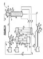
- FIG. 1 illustrates an exemplary embodiment of the invention as applied to a pre-cooled refrigerant system and process.
- propane is used to precool both a natural gas feed stream 102 and a liquefaction refrigerant stream 104.
- the natural gas feed stream 102 may be pretreated, for example.
- the liquefaction refrigerant stream 104 may be a pure or a mixed refrigerant, for example. It should be noted that while the exemplary embodiments described below may refer to the liquefaction refrigerant stream as a mixed refrigerant stream, the liquefaction refrigerant stream described below may also be a pure refrigerant stream, for example.
- refrigerant availability in the local area and system requirements e .
- the liquefaction refrigerant stream 104 may comprise one or more of the following: nitrogen, methane, ethylene, ethane, propylene, propane, iso-butane, n-butane, and iso-pentane, for example.
- the compression of the propane vapor resulting from the cooling of the natural gas feed stream 102 may occur in one compressor 118 while the compression of the propane vapor generated from cooling of liquefaction refrigerant stream 104 may occur in a separate compressor 126.
- Precooling of the natural gas feed stream 102 and the mixed refrigerant stream 104 may be accomplished by vaporizing a precooling refrigerant such as propane at four different pressure levels in closed-loop precooling refrigeration system(s).
- the natural gas feed stream 102 may be precooled because of equipment limitations and for efficiency purposes.
- propane may be used as the precooling refrigerant for vaporizing at four different pressure levels (as illustrated in exemplary Figures 1-7A )
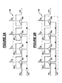
- Unit 106 may comprise a series of heat exchangers, valves, and separators as illustrated in Figure 2A .
- Natural gas feed stream 102 is cooled by indirect heat exchange against a precooling refrigerant in a series of propane evaporators 202, 204, 206, 208 that may operate at successively lower pressures (202 being the highest and 208 being the lowest, for example) producing cooled successive streams 203, 205, 207, and 150.
- propane evaporators 202, 204, 206, 208 that may operate at successively lower pressures (202 being the highest and 208 being the lowest, for example) producing cooled successive streams 203, 205, 207, and 150.
- propane evaporators 202, 204, 206, 208 that may operate at successively lower pressures (202 being the highest and 208 being the lowest, for example) producing cooled successive streams 203, 205, 207, and 150.
- propane evaporators 202, 204, 206, 208 that may
- propane condenser 122 The resulting compressed stream 120 is then condensed in propane condenser 122, producing liquid stream 124 for reintroduction into the series of propane evaporators 202, 204, 206, 208.
- propane condensers used in these types of methods and systems may include, for example, a propane de-superheater, a condenser, an accumulator, and a propane subcooler.
- the pre-cooling system may comprise a single-stage, a two-stage, a three-stage, or systems with greater than four stages, for example, where the series of propane evaporators may operate at successively lower pressures.
- Cooling of the mixed refrigerant stream 104 is performed in unit 108.
- Unit 108 may also comprise a series of heat exchangers, valves, and separators as illustrated in Figure 2B .
- the mixed refrigerant stream 104 may also be cooled by indirect heat exchange against the precooling refrigerant in a series of propane evaporators 222, 224, 226, 228 that may operate at successively lower pressures (222 being the highest and 228 being the lowest, for example) producing cooled successive streams 223, 225, 227, and 138.
- propane evaporators 222, 224, 226, 228 that may operate at successively lower pressures (222 being the highest and 228 being the lowest, for example) producing cooled successive streams 223, 225, 227, and 138.
- propane evaporators 222, 224, 226, 228 that may operate at successively lower pressures (222 being the highest and 228 being the lowest, for example) producing cooled successive streams 223, 225, 227, and
- Cooled mixed refrigerant stream 138 is separated in phase separator 140 into a liquid mixed refrigerant stream 142 and a vapor mixed refrigerant stream 144.
- Liquid mixed refrigerant stream 142 is sub-cooled in the cryogenic heat exchanger (MCHE) 146 producing stream 147.
- Stream 147 may then be reduced in pressure through isenthalpic valve 148 producing stream 149.
- Stream 149 may then be vaporized in the shell side of the MCHE 146 to provide cooling to tubeside streams 142, 144, 150.
- Vapor mixed refrigerant steam 144 is condensed and sub-cooled in the MCHE 146 to produce stream 151.
- Stream 151 may then be reduced in pressure through isenthalpic valve 152 to produce stream 153.
- Stream 153 may then be vaporized in the shell side of the MCHE 146 to provide cooling to tubeside streams 142, 144, 150.
- the cooled natural gas feed stream 150 may enter the MCHE 146 where it is further cooled producing product stream 166 that may be, for example, liquid natural gas (LNG).
- LNG liquid natural gas
- Low pressure mixed refrigerant stream 145 exiting the MCHE 146 is compressed in the low pressure mixed refrigerant compressor 154 to produce stream 155.
- the refrigerant compressors of all of the exemplary embodiments may include one or more intercoolers and compressor casings.
- mixed refrigerant compressor 154 may include one or more intercoolers and at least one compressor casing. Intercoolers and aftercoolers use an ambient heat sink (air or water) to reject compression heat to the environment.
- Stream 155 is cooled in intercooler 156 to produce stream 157.
- Stream 157 is further compressed in the medium pressure mixed refrigerant compressor 158 to produce stream 159.
- Stream 159 is cooled in intercooler 160 to produce stream 161.
- Stream 161 is further compressed in high pressure mixed refrigerant compressor 162 to produce stream 163.
- Stream 163 is cooled in aftercooler 164 to be recycled back as original mixed refrigerant stream 104.
- the exemplary embodiment illustrated in Figure 1 shows how the power supplied to the refrigeration compressors 118, 126, 154, 158, 162 are provided by two equal sized directly connected gas turbines 180, 182.
- mixed refrigerant compressors 154, 158 are driven by gas turbine driver 180 while mixed refrigerant compressor 160 and the propane compressors 118, 126 are driven by gas turbine driver 182.
- the design pressure level between the mixed refrigerant compressors 158 and 162 may be chosen such that the work required by the two gas turbine drivers 180, 182 is essentially equal.
- the gas turbine drivers in all exemplary embodiments may be single-shaft gas turbines or multi-shaft gas turbines, for example.
- This exemplary embodiment is independent of the method used to power the refrigeration compressors 118, 126, 154, 158 and 162.
- the refrigeration compressors 118, 126, 154, 158 and 162, and the refrigeration compressors of the other exemplary embodiments may be driven by one or more gas turbines, electric motors, steam turbines, or a combination of different drivers.
- the gas turbines 180, 182 may include starter/helper electric motors 184, 186 respectively to assist in starting the gas turbines 180, 182 and optimally, to provide additional power to assist the gas turbines 180, 182, or to generate power for exportation into the power grid when excess power is available from the gas turbines.
- starter/helper electric motor 186 in Figure 1 may be positioned away from and not adjacent to driver 182 (i.e., at the opposite end of the driver string).
- the positions of the compressor bodies 118, 126, 162 may also be exchanged.
- Figure 3 illustrates another exemplary embodiment 300 where the propane compressors 318, 326 are powered by different drivers 380, 382 respectively.
- the power demand from the equivalent gas turbine drivers 380, 382 may be balanced by adjustment of the discharge pressure of low pressure mixed refrigerant compressor 354.
- unit 306 may comprise a series of heat exchangers, valves, and separators as illustrated in Figure 2A .
- Natural gas feed stream 302 is cooled by indirect heat exchange to ultimately produce cooled stream 350.
- the evaporation of propane at the four pressures results in four propane vapor streams 310, 312, 314, 316 that may then be compressed in compressor 318.
- the resulting compressed stream 320 may then be condensed in propane condenser 322, producing liquid stream 324 for reintroduction into the series of propane evaporators as shown in Figure 2A .
- Cooling of the mixed refrigerant stream 304 is performed in unit 308.
- Unit 308 may also comprise a series of heat exchangers, valves, and separators as illustrated in Figure 2B .
- the mixed refrigerant stream 304 may also be cooled by indirect heat exchange to ultimately produce cooled stream 338.
- the evaporation of propane at the four pressures results in four propane vapor streams 330, 332, 334, 336 that may then be compressed in compressor 326.
- the resulting compressed stream 327 may then be condensed in propane condenser 328, producing liquid stream 329 for reintroduction into the series of propane evaporators as shown in Figure 2B .
- cooled mixed refrigerant stream 338 is separated in phase separator 340 into a liquid mixed refrigerant stream 342 and a vapor mixed refrigerant stream 344.
- Liquid mixed refrigerant stream 342 is sub-cooled in the cryogenic heat exchanger (MCHE) 346 producing stream 347.
- Stream 347 may then be reduced in pressure through isenthalpic valve 348 producing stream 349.
- Stream 349 may then be vaporized in the shell side of the MCHE 346 to provide cooling to tubeside streams 342, 344, 350.
- Vapor mixed refrigerant steam 344 is condensed and sub-cooled in the MCHE 346 to produce stream 351.
- Stream 351 may then be reduced in pressure through isenthalpic valve 352 to produce stream 353.
- Stream 353 may then be vaporized in the shell side of the MCHE 346 to provide cooling to tubeside streams 342, 344, 350.
- the cooled natural gas feed stream 350 may enter the MCHE 346 where it is further cooled producing product stream 366 that may be, for example, liquid natural gas (LNG).
- LNG liquid natural gas
- Low pressure mixed refrigerant stream 345 exiting the MCHE 346 is compressed in the low pressure refrigerant compressor 354 to produce stream 355.
- Stream 355 is cooled in intercooler 356 to produce stream 357.
- Stream 357 is further compressed in the high pressure refrigerant compressor 362 to produce stream 363.
- Stream 363 is cooled in aftercooler 364 to be recycled back as original mixed refrigerant stream 304.
- the gas turbines 380, 382 may include starter/helper electric motors 384, 386 respectively to assist in starting the gas turbines 380, 382 and optimally, to provide additional power to assist the gas turbines 380, 382, or for exportation into the power grid when excess power is available from the gas turbines.
- Figure 4 illustrates another exemplary embodiment 400 where the position of compressors 418, 426 of Figure 3 may be swapped such that one of the drivers provides power to the propane compressor 418 and the high pressure refrigerant compressor 462, while the other driver provides power to the propane compressor 426 and the low pressure refrigerant compressor 454.
- unit 406 may comprise a series of heat exchangers, valves, and separators as illustrated in Figure 2A .
- Natural gas feed stream 402 is cooled by indirect heat exchange to ultimately produce cooled stream 450.
- the evaporation of propane at the four pressures results in four propane vapor streams 410, 412, 414, 416 that may then be compressed in compressor 418.
- the resulting compressed stream 420 may then be condensed in propane condenser 422, producing liquid stream 424 for reintroduction into the series of propane evaporators as shown in Figure 2A .
- Cooling of the mixed refrigerant stream 404 is performed in unit 408.
- Unit 408 may also comprise a series of heat exchangers, valves, and separators as illustrated in Figure 2B .
- the mixed refrigerant stream 404 may also be cooled by indirect heat exchange to ultimately produce cooled stream 438.
- the evaporation of propane at the four pressures results in four propane vapor streams 430, 432, 434, 436 that may then be compressed in compressor 426.
- the resulting compressed stream 427 may then be condensed in propane condenser 428, producing liquid stream 429 for reintroduction into the series of propane evaporators as shown in Figure 2B .
- cooled mixed refrigerant stream 438 is separated in phase separator 440 into a liquid mixed refrigerant stream 442 and a vapor mixed refrigerant stream 444.
- Liquid mixed refrigerant stream 442 is sub-cooled in the cryogenic heat exchanger (MCHE) 446 producing stream 447.
- Stream 447 may then be reduced in pressure through isenthalpic valve 448 producing stream 449.
- Stream 449 may then be vaporized in the shell side of the MCHE 446 to provide cooling to tubeside streams 442, 444, 450.
- Vapor mixed refrigerant steam 444 is condensed and sub-cooled in the MCHE 446 to produce stream 451.
- Stream 451 may then be reduced in pressure through isenthalpic valve 452 to produce stream 453.
- Stream 453 may then be vaporized in the shell side of the MCHE 446 to provide cooling to tubeside streams 442, 444, 450.
- the cooled natural gas feed stream 450 may enter the MCHE 446 where it is further cooled producing product stream 466 that may be, for example, liquid natural gas (LNG).
- LNG liquid natural gas
- Low pressure mixed refrigerant stream 445 exiting the MCHE 446 is compressed in the low pressure refrigerant compressor 454 to produce stream 455.
- Stream 455 is cooled in intercooler 456 to produce stream 457.
- Stream 457 is further compressed in high pressure refrigerant compressor 462 to produce stream 463.
- Stream 463 is cooled in aftercooler 464 to be recycled back as original mixed refrigerant stream 404.
- Gas turbines 480, 482 may include starter/helper electric motors 484, 486 respectively to assist in starting the gas turbines 480, 482 and optimally, to provide additional power to assist the gas turbines 480, 482, or for exportation into the power grid when excess power is available from the gas turbines.
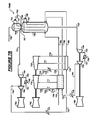
- FIG. 5 illustrates yet another exemplary embodiment 500 as applied to a three loop refrigeration system.
- unit 506 precools a third refrigerant stream 503 in addition to the natural gas feed stream 502.
- unit 506 may comprise a series of heat exchangers, valves, and separators as illustrated in Figure 2A .
- Natural gas feed stream 502 is cooled by indirect heat exchange to ultimately produce cooled stream 550.
- the evaporation of propane at the four pressures results in four propane vapor streams 510, 512, 514, 516 that may then be compressed in compressor 518.
- the resulting compressed stream 520 may then be condensed in propane condenser 522, producing liquid stream 524 for reintroduction into the series of propane evaporators as shown in Figure 2A .
- Cooling of the mixed refrigerant stream 504 is performed in unit 508.
- Unit 508 may also comprise a series of heat exchangers, valves, and separators as illustrated in Figure 2B .
- the mixed refrigerant stream 504 may also be cooled by indirect heat exchange to ultimately produce cooled stream 538.
- the evaporation of propane at the four pressures results in four propane vapor streams 530, 532, 534, 536 that may then be compressed in compressor 526.
- the resulting compressed stream 527 may then be condensed in propane condenser 528, producing liquid stream 529 for reintroduction into the series of propane evaporators as shown in Figure 2B .
- Cooled mixed refrigerant stream 538 is subcooled in the cryogenic heat exchanger (MCHE) 546 producing stream 547.
- Stream 547 may then be reduced in pressure through isenthalpic valve 548 producing stream 549.
- Stream 549 may then be vaporized in the shell side of the MCHE 546 to provide cooling to tubeside streams 505, 538, and 550.
- Cooled mixed refrigerant stream 505 may also be subcooled and liquefied in MCHE 546 producing stream 569 then subcooled in exchanger 568 producing stream 551.
- Exchanger 568 may be a wound coil type exchanger, for example.
- the resulting stream 551 may then be reduced in pressure through isenthalpic valve 552 to produce stream 553.
- Stream 553 may then be vaporized in exchanger 568 to provide refrigeration for subcooling both the feed gas stream (entering as stream 567 and exiting as 566) and the third refrigerant stream 569.
- third refrigerant stream 553 exits exchanger 568 as stream 593 and is then compressed by compressor 594 to produce stream 595.
- Stream 595 is then cooled in the mixed refrigerant intercooler 596 to produce stream 597.
- Stream 597 is compressed in compressor 598 to produce stream 599.
- Stream 599 is then cooled in mixed refrigerant aftercooler 501 to be recycled back as original stream 503.
- the cooled natural gas feed stream 550 may enter the MCHE 546 where it is further cooled producing stream 567. Stream 567 may then be subcooled in exchanger 568 to produce product stream 566 that may be, for example, liquid natural gas (LNG).
- LNG liquid natural gas
- Low pressure mixed refrigerant stream 545 exiting the MCHE 546 is compressed in the low pressure refrigerant compressor 554 to produce stream 555.
- Stream 555 is cooled in intercooler 556 to produce stream 557.
- Stream 557 is further compressed in high pressure refrigerant compressor 558 to produce stream 559.
- Stream 559 is cooled in aftercooler 564 to be recycled back as original mixed refrigerant stream 504.
- the gas turbines may include starter/helper electric motors (not shown in this embodiment) to assist in starting the gas turbines and optimally, to provide additional power to assist the gas turbines, or for exportation into the power grid when excess power is available from the gas turbines.
- Figure 6 illustrates yet another exemplary embodiment 600 as applied to another three loop refrigeration system.
- unit 606 precools the natural gas feed stream 602 only.
- unit 606 may comprise a series of heat exchangers, valves, and separators as illustrated in Figure 2A .
- Natural gas feed stream 602 is cooled by indirect heat exchange to ultimately produce cooled stream 650.
- the evaporation of propane at the four pressures results in four propane vapor streams 610, 612, 614, 616 that may then be compressed in compressor 618.
- the resulting compressed stream 620 may then be condensed in propane condenser 622, producing liquid stream 624 for reintroduction into the series of propane evaporators as shown in Figure 2A .
- both mixed refrigerant streams 603, 604 are cooled in unit 608.
- Unit 608 may also comprise a series of heat exchangers, valves, and separators as illustrated in Figure 2B .
- the mixed refrigerant streams 603, 604 may also be cooled by indirect heat exchange to ultimately produce cooled streams 605, 638.
- the evaporation of propane at the four pressures results in four propane vapor streams 630, 632, 634, 636 that may then be compressed in compressor 626.
- the resulting compressed stream 627 may then be condensed in propane condenser 628, producing liquid stream 629 for reintroduction into the series of propane evaporators as shown in Figure 2B .
- Cooled mixed refrigerant stream 638 is subcooled in the cryogenic heat exchanger (MCHE) 646 producing stream 647.
- Stream 647 may then be reduced in pressure through isenthalpic valve 648 producing stream 649.
- Stream 649 may then be vaporized in the shell side of the MCHE 646 to provide cooling to tubeside streams 605, 638, and 650.
- Cooled mixed refrigerant stream 605 may also be subcooled and liquefied in MCHE 646 producing stream 669 then subcooled in exchanger 668 producing stream 651.
- Exchanger 668 may be a wound coil type exchanger, for example.
- the resulting stream 651 may then be reduced in pressure through isenthalpic valve 652 to produce stream 653.
- Stream 653 may then be vaporized in exchanger 668 to provide refrigeration for subcooling both the feed gas stream (entering as stream 667 and exiting as 666) and the third refrigerant stream 669.
- third refrigerant stream 653 exits exchanger 668 as stream 693 and is then compressed by compressor 694 to produce stream 695.
- Stream 695 is then cooled in the mixed refrigerant intercooler 696 to produce stream 697.
- Stream 697 is compressed in compressor 698 to produce stream 699.
- Stream 699 is then cooled in mixed refrigerant aftercooler 601 to be recycled back as original stream 603.
- the cooled natural gas feed stream 650 may enter the MCHE 646 where it is further cooled producing stream 667. Stream 667 may then be subcooled in exchanger 668 to produce product stream 666 that may be, for example, liquid natural gas (LNG).
- LNG liquid natural gas
- Low pressure mixed refrigerant stream 645 exiting the MCHE 646 is compressed in the low pressure refrigerant compressor 654 to produce stream 655.
- Stream 655 is cooled in intercooler 656 to produce stream 657.
- Stream 657 is further compressed in the high pressure refrigerant compressor 658 to produce stream 659.
- Stream 659 is cooled in aftercooler 664 to be recycled back as original mixed refrigerant stream 604.
- the gas turbines may include starter/helper electric motors (not shown in this embodiment) to assist in starting the gas turbines and optimally, to provide additional power to assist the gas turbines, or for exportation into the power grid when excess power is available from the gas turbines.
- FIG. 7A illustrates another exemplary embodiment 700A as applied to yet another three loop refrigeration system.
- unit 706 precools the natural gas feed stream 702 and the mixed refrigerant stream 704.
- unit 706 may comprise a series of heat exchangers, valves, and separators as illustrated in Figure 2A .
- Natural gas feed stream 702 and mixed refrigerant stream 704 is cooled by indirect heat exchange to ultimately produce cooled streams 750, 738.
- the evaporation of propane at the four pressures results in four propane vapor streams 710, 712, 714, 716 that may then be compressed in compressor 718.
- the resulting compressed stream 720 may then be condensed in propane condenser 722, producing liquid stream 724 for reintroduction into the series of propane evaporators as shown in Figure 2A .
- unit 708 may also comprise a series of heat exchangers, valves, and separators as illustrated in Figure 2B .
- the mixed refrigerant stream 703 is cooled by indirect heat exchange to ultimately produce cooled streams 705.
- the evaporation of propane at the four pressures results in four propane vapor streams 730, 732, 734, 736 that may then be compressed in compressor 726.
- the resulting compressed stream 727 may then be condensed in propane condenser 728, producing liquid stream 729 for reintroduction into the series of propane evaporators as shown in Figure 2B .
- Cooled mixed refrigerant stream 738 is subcooled in the cryogenic heat exchanger (MCHE) 746 producing stream 747.
- Stream 747 may then be reduced in pressure through isenthalpic valve 748 producing stream 749.
- Stream 749 may then be vaporized in the shell side of the MCHE 746 to provide cooling to tubeside streams 705, 738, and 750.
- Cooled mixed refrigerant stream 705 may also be subcooled and liquefied in MCHE 746 producing stream 769 then subcooled in exchanger 768 producing stream 751.
- Exchanger 768 may be a wound coil type exchanger, for example.
- the resulting stream 751 may then be reduced in pressure through isenthalpic valve 752 to produce stream 753.
- Stream 753 may then be vaporized in exchanger 768 to provide refrigeration for subcooling both the feed gas stream (entering as stream 767 and exiting as 766) and the third refrigerant stream 769.
- third refrigerant stream 753 exits exchanger 768 as stream 793 and is then compressed by compressor 794 to produce stream 795.
- Stream 795 is then cooled in the mixed refrigerant intercooler 796 to produce stream 797.
- Stream 797 is compressed in compressor 798 to produce stream 799.
- Stream 799 is then cooled in mixed refrigerant aftercooler 701 to be recycled back as original stream 703.
- the cooled natural gas feed stream 750 may enter the MCHE 746 where it is further cooled producing stream 767. Stream 767 may then be subcooled in exchanger 768 to produce product stream 766 that may be, for example, liquid natural gas (LNG).
- LNG liquid natural gas
- Low pressure mixed refrigerant stream 745 exiting the MCHE 746 is compressed in the low pressure refrigerant compressor 754 to produce stream 755.
- Stream 755 is cooled in intercooler 756 to produce stream 757.
- Stream 757 is further compressed in the high pressure refrigerant compressor 758 to produce stream 759.
- Stream 759 is cooled in aftercooler 764 to be recycled back as original mixed refrigerant stream 704.
- the gas turbines may include starter/helper electric motors (not shown in this embodiment) to assist in starting the gas turbines and optimally, to provide additional power to assist the gas turbines, or for exportation into the power grid when excess power is available from the gas turbines.
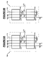
- Figure 7B illustrates yet another exemplary embodiment 700B similar to 700A, however, in this exemplary embodiment 700B, unit 706 precools the natural gas feed stream 702 and the mixed refrigerant stream 704 through indirect heat exchange with a mixed refrigerant stream in a two-stage mixed refrigerant precooling system. While Figure 7B discloses use of a two-stage mixed refrigerant precooling system, the precooling may be performed using a single-stage mixed refrigerant precooling system, or mixed refrigerant precooling systems with greater than two stages, for example. Additionally, a mixed refrigerant precooling system may be interchanged with the propane precooling systems disclosed in any of the exemplary embodiments.
- FIGS 8A and 8B illustrate exemplary units 706 and 708 shown in Figure 7B .
- Unit 706 may comprise two heat exchangers 810, 812 where streams 702, 704, and at least a portion of stream 724 are cooled through indirect heat exchange against stream 713 in heat exchanger 810.
- Stream 724 enters heat exchanger 810 and is cooled producing stream 830.
- Stream 830 is split into two streams 831, 832 where stream 831 is further cooled in heat exchanger 812 while stream 832 is let down in pressure across isenthalpic valve 814 to produce stream 833.
- Stream 833 then enters heat exchanger 810 to provide cooling to streams 702, 704, 724 and exits the heat exchanger 810 as stream 713.
- stream 831 is cooled in heat exchanger 812 to produce stream 834 and let down in pressure across isenthalpic valve 816, the resulting stream 835 is introduced into heat exchanger 812 to provide further cooling for resultant streams 738, 750, 834.
- Unit 708 may comprise two heat exchangers 818, 820 where streams 703, 729 are cooled through indirect heat exchange against stream 733 in heat exchanger 818.
- Stream 729 enters heat exchanger 818 and is cooled producing stream 840.
- Stream 840 is split into two streams 841, 842 where stream 841 is further cooled in heat exchanger 820 while stream 842 is let down in pressure across isenthalpic valve 822 to produce stream 843.
- Stream 843 then enters heat exchanger 818 to provide cooling to streams 703, 729 and exits the heat exchanger 818 as stream 733.
- stream 841 is cooled in heat exchanger 820 to produce stream 844 and let down in pressure across isenthalpic valve 824, the resulting stream 845 is introduced into heat exchanger 820 to provide further cooling for resultant streams 705, 844.
- Heat exchangers 810, 812, 818, 820 may be wound-coil heat exchangers, plate-and-fin brazed aluminum (core) type heat exchangers, or shell and tube heat exchangers, for example. Heat exchangers 810, 812 may be combined into a single heat exchanger, for example. Heat exchangers 818, 820 may also be combined into a single heat exchanger, for example. Finally, heat exchangers 810, 812, 818, 820 may be combined into a single heat exchanger, for example. Heat exchangers 810, 812, 818, 820 may accept two or more load streams, for example.
- core plate-and-fin brazed aluminum
- Pre-cooling in units 106, 108 may provide, for example, enough cooling to feed stream 102 and liquefaction refrigerant stream 104 such that the temperatures of streams 150 and 138 may reach +60°F (+16°C) to as low as -100°F (-73°C) before further cooling in the MCHE 146.
- the same cooling ranges may be achieved in Figures 3-7B .
- propane may be used as the pre-cooling refrigerant to reach the temperature range of +20°F to -40°F (-7°C to -40°C).
- the isenthalpic valves 148, 152 may optionally be replaced by work extracting liquid turbines, for example, to improve efficiency.
- propane condensers 122, 128 (and the corresponding propane condensers in Figures 3-7A ) may be ambient heat sink coolers used to condense, desuperheat, and/or optimally subcool precooling refrigerant, for example.
- the natural gas feed stream 102 entered unit 106 after pretreatment, including the removal of moisture (H 2 O), carbon dioxide (CO 2 ), sulfur dioxide (SO 2 ), mercury, and other heavy components, including, but not limited to, benzene, ethylbenzene, and toluene, if they exist in the natural gas feed stream 102 in concentrations that would lead to freezing in the MCHE 146.
- the pretreated natural gas feed stream 102 was at 35°C and 40 bar absolute and had a flow rate of 12,260 kg-mole/hr.
- Natural gas feed stream 102 was cooled by indirect heat exchange in a series of propane evaporators 202, 204, 206, 208 (illustrated in Figure 2A ) that operate at successively lower pressures of 7.16 bar, 4.25 bar, 2.54 bar and 1.47 bar, where propane evaporator 202 is at the highest pressure and propane evaporator 208 is at the lowest pressure.
- propane evaporator 202 is at the highest pressure
- propane evaporator 208 is at the lowest pressure.
- the evaporation of propane at the four pressures resulted in four propane vapor streams 110, 112, 114, 116 that were then compressed in compressor 118.
- Resulting stream 120 (at 16.2 bar, and 10,930 kgmole/hr) was then condensed in propane condenser 122 using an ambient heat sink (air or water), producing liquid stream 124.
- the natural gas feed stream 102 was precooled by the propane to -22.5 °C. Resulting cooled stream 150 was then cooled and liquefied in MCHE 146 by vaporizing mixed refrigerant producing liquid natural gas (LNG) stream 166 at -163.3°C.
- LNG liquid natural gas
- the mixed refrigerant stream 104 had a molar composition as follows: Table I Component Mole Composition (%) Nitrogen 12 Methane 38 Ethane 42 Propane 8
- the mixed refrigerant stream 104 was at 35 °C and 62 bar absolute and had a flow rate of 50,250 kg-mole/hr.
- the mixed refrigerant stream 104 was cooled by indirect heat exchange in a series of propane evaporators 222, 224, 226, 228 (illustrated in Figure 2B ) that operate at successively lower pressures of 7.16 bar absolute, 4.25 bar, 2.54 bar and 1.47 bar where propane evaporator 203 is the highest and propane evaporator 209 is the lowest.
- propane evaporator 203 is the highest and propane evaporator 209 is the lowest.
- the evaporation of propane at the four pressures results in four propane vapor streams 130, 132, 134, 138 which are then compressed in compressor 126.
- Resulting stream 127 (at 16.2 bar absolute and 31,600 kgmole/hr) is condensed in propane condenser 128 using an ambient heat sink (air or water), producing liquid stream 129.
- the precooled mixed refrigerant stream 138 is then separated into liquid stream 142 and vapor stream 144 in phase separator 140.
- Liquid stream 142 is then subcooled to -125°C, flashed isenthalpically through valve 148, and then vaporized in the shell side of exchanger 146 to provide cooling to the tubeside streams 142, 144, 150.
- Vapor stream 144 is liquefied, subcooled to a temperature of -163°C, flashed isenthalpically through valve 152, and then vaporized and warmed in the shell side of exchanger 146 to provide cooling to the tubeside streams 142, 144, 150.
- the combined mixed refrigerant stream 145 exits the MCHE 146 at a temperature of - 32.7°C and a pressure of 4.14 bar absolute.
- the combined mixed refrigerant stream 154 is then compressed in three stages of compressors 156, 158, 160 back to a pressure of 62 bar absolute, completing the loop.
- the exemplary embodiment of Figure 1 allows more optimal and feasible compressor designs than the system disclosed in U.S. Patent No. 6,962,061 using the same number of compressor casings and providing the same pre-cooling service. This is achieved by segregating the heat loads requiring pre-cooling refrigeration into two independent systems.
Landscapes
- Engineering & Computer Science (AREA)
- Physics & Mathematics (AREA)
- Mechanical Engineering (AREA)
- Thermal Sciences (AREA)
- General Engineering & Computer Science (AREA)
- Chemical & Material Sciences (AREA)
- Chemical Kinetics & Catalysis (AREA)
- General Chemical & Material Sciences (AREA)
- Oil, Petroleum & Natural Gas (AREA)
- Separation By Low-Temperature Treatments (AREA)
Applications Claiming Priority (1)
| Application Number | Priority Date | Filing Date | Title |
|---|---|---|---|
| US12/333,500 US20100147024A1 (en) | 2008-12-12 | 2008-12-12 | Alternative pre-cooling arrangement |
Publications (2)
| Publication Number | Publication Date |
|---|---|
| EP2199716A2 true EP2199716A2 (de) | 2010-06-23 |
| EP2199716A3 EP2199716A3 (de) | 2012-08-08 |
Family
ID=42062483
Family Applications (1)
| Application Number | Title | Priority Date | Filing Date |
|---|---|---|---|
| EP09178825A Withdrawn EP2199716A3 (de) | 2008-12-12 | 2009-12-11 | Alternative Vorkühlungsanordnung |
Country Status (11)
| Country | Link |
|---|---|
| US (1) | US20100147024A1 (de) |
| EP (1) | EP2199716A3 (de) |
| JP (1) | JP2010189622A (de) |
| KR (1) | KR20100068194A (de) |
| CN (1) | CN101845340A (de) |
| AU (1) | AU2009245831A1 (de) |
| BR (1) | BRPI0904895A2 (de) |
| CA (1) | CA2687673A1 (de) |
| PE (1) | PE20100569A1 (de) |
| RU (1) | RU2009146074A (de) |
| TW (1) | TW201027018A (de) |
Cited By (9)
| Publication number | Priority date | Publication date | Assignee | Title |
|---|---|---|---|---|
| AU2013203120B2 (en) * | 2012-09-18 | 2014-09-04 | Woodside Energy Technologies Pty Ltd | Production of ethane for startup of an lng train |
| US9441877B2 (en) | 2010-03-17 | 2016-09-13 | Chart Inc. | Integrated pre-cooled mixed refrigerant system and method |
| WO2019008267A1 (fr) | 2017-07-05 | 2019-01-10 | Engie | Dispositif et procédé de liquéfaction d'un gaz naturel ou d'un biogaz |
| US10480851B2 (en) | 2013-03-15 | 2019-11-19 | Chart Energy & Chemicals, Inc. | Mixed refrigerant system and method |
| US10663221B2 (en) | 2015-07-08 | 2020-05-26 | Chart Energy & Chemicals, Inc. | Mixed refrigerant system and method |
| US11408673B2 (en) | 2013-03-15 | 2022-08-09 | Chart Energy & Chemicals, Inc. | Mixed refrigerant system and method |
| US11428463B2 (en) | 2013-03-15 | 2022-08-30 | Chart Energy & Chemicals, Inc. | Mixed refrigerant system and method |
| EP4230937A1 (de) * | 2022-02-21 | 2023-08-23 | Linde GmbH | Verfahren und anlage zur erzeugung eines verflüssigten kohlenwasserstoffprodukts |
| US12104849B2 (en) | 2022-08-05 | 2024-10-01 | Chart Energy & Chemicals, Inc. | Mixed refrigerant system and method |
Families Citing this family (21)
| Publication number | Priority date | Publication date | Assignee | Title |
|---|---|---|---|---|
| KR101107437B1 (ko) * | 2010-03-25 | 2012-01-19 | 한국가스공사연구개발원 | 천연가스 액화공정 |
| KR101037226B1 (ko) * | 2010-10-26 | 2011-05-25 | 한국가스공사연구개발원 | 천연가스 액화공정 |
| US8721916B2 (en) | 2011-05-12 | 2014-05-13 | A.S. Trust & Holdings Inc. | Refrigerant composition |
| CN102425899B (zh) * | 2011-11-03 | 2014-01-01 | 苏州市兴鲁空分设备科技发展有限公司 | 低温装置中低温冷冻机的使用方法 |
| KR101378995B1 (ko) | 2012-03-22 | 2014-04-02 | 삼성중공업 주식회사 | 이산화탄소 운영 시스템 및 방법 |
| EP2859290A4 (de) * | 2012-06-06 | 2016-11-30 | Keppel Offshore & Marine Technology Ct Pte Ltd | System und verfahren zur erdgasverflüssigung |
| KR101341798B1 (ko) * | 2012-08-10 | 2013-12-17 | 한국과학기술원 | 천연가스 액화시스템 |
| ITFI20130076A1 (it) * | 2013-04-04 | 2014-10-05 | Nuovo Pignone Srl | "integrally-geared compressors for precooling in lng applications" |
| US11874055B2 (en) * | 2014-03-04 | 2024-01-16 | Conocophillips Company | Refrigerant supply to a cooling facility |
| US20160076808A1 (en) * | 2014-09-15 | 2016-03-17 | Propak Systems Ltd. | Method and system for treating and liquefying natural gas |
| EP3230669A4 (de) | 2014-12-12 | 2018-08-01 | Dresser Rand Company | System und verfahren zur verflüssigung von erdgas |
| CN105211267A (zh) * | 2015-09-17 | 2016-01-06 | 北京市农林科学院 | 多级果蔬预冷机 |
| CA3004929C (en) * | 2015-11-09 | 2021-02-09 | Bechtel Hydrocarbon Technology Solutions, Inc. | Systems and methods for multi-stage refrigeration |
| US10359228B2 (en) | 2016-05-20 | 2019-07-23 | Air Products And Chemicals, Inc. | Liquefaction method and system |
| IT201600109378A1 (it) * | 2016-10-28 | 2018-04-28 | Nuovo Pignone Tecnologie Srl | Sistema di liquefazione di gas naturale comprendente un turbocompressore con moltiplicatore integrato |
| US10544986B2 (en) * | 2017-03-29 | 2020-01-28 | Air Products And Chemicals, Inc. | Parallel compression in LNG plants using a double flow compressor |
| SG11201910083RA (en) | 2017-05-16 | 2019-11-28 | Exxonmobil Upstream Res Co | Method and system for efficient nonsynchronous lng production using large scale multi-shaft gas tusbines |
| JP7229230B2 (ja) * | 2018-03-27 | 2023-02-27 | 大陽日酸株式会社 | 天然ガス液化装置および天然ガス液化方法 |
| GB2582763A (en) * | 2019-04-01 | 2020-10-07 | Linde Ag | Method and device for the recovery of waste energy from refrigerant compression systems used in gas liquefaction processes |
| CA3170660A1 (en) | 2020-02-25 | 2021-09-02 | Shell Internationale Research Maatschappij B.V. | Method and system for production optimization |
| DE102020006396A1 (de) * | 2020-10-17 | 2022-04-21 | Linde Gmbh | Verfahren und Anlage zur Erzeugung eines verflüssigten Kohlenwasserstoffprodukts |
Citations (1)
| Publication number | Priority date | Publication date | Assignee | Title |
|---|---|---|---|---|
| EP1471319A1 (de) * | 2003-04-25 | 2004-10-27 | Totalfinaelf S.A. | Anlage und Verfahren zum Verflüssigen von Erdgas |
Family Cites Families (20)
| Publication number | Priority date | Publication date | Assignee | Title |
|---|---|---|---|---|
| US3763658A (en) * | 1970-01-12 | 1973-10-09 | Air Prod & Chem | Combined cascade and multicomponent refrigeration system and method |
| US4057972A (en) * | 1973-09-14 | 1977-11-15 | Exxon Research & Engineering Co. | Fractional condensation of an NG feed with two independent refrigeration cycles |
| FR2280041A1 (fr) * | 1974-05-31 | 1976-02-20 | Teal Technip Liquefaction Gaz | Procede et installation pour le refroidissement d'un melange gazeux |
| US4445916A (en) * | 1982-08-30 | 1984-05-01 | Newton Charles L | Process for liquefying methane |
| US4525185A (en) * | 1983-10-25 | 1985-06-25 | Air Products And Chemicals, Inc. | Dual mixed refrigerant natural gas liquefaction with staged compression |
| GB2149902B (en) * | 1983-11-18 | 1987-09-03 | Shell Int Research | A method and a system for liquefying a gas in particular a natural gas |
| JPH06299174A (ja) * | 1992-07-24 | 1994-10-25 | Chiyoda Corp | 天然ガス液化プロセスに於けるプロパン系冷媒を用いた冷却装置 |
| DE59510130D1 (de) * | 1995-07-31 | 2002-05-02 | Man Turbomasch Ag Ghh Borsig | Kompressionsvorrichtung |
| US5611216A (en) * | 1995-12-20 | 1997-03-18 | Low; William R. | Method of load distribution in a cascaded refrigeration process |
| NO300293B1 (no) * | 1996-03-06 | 1997-05-05 | Norske Stats Oljeselskap | Anlegg for fremstilling av flytendegjort naturgass |
| DE19722490C1 (de) * | 1997-05-28 | 1998-07-02 | Linde Ag | Verfahren zum Verflüssigen eines Kohlenwasserstoff-reichen Stromes |
| US6347532B1 (en) * | 1999-10-12 | 2002-02-19 | Air Products And Chemicals, Inc. | Gas liquefaction process with partial condensation of mixed refrigerant at intermediate temperatures |
| MY125082A (en) * | 1999-12-15 | 2006-07-31 | Shell Int Research | Compression apparatus for gaseous refrigerant |
| GB0006265D0 (en) * | 2000-03-15 | 2000-05-03 | Statoil | Natural gas liquefaction process |
| US6691531B1 (en) * | 2002-10-07 | 2004-02-17 | Conocophillips Company | Driver and compressor system for natural gas liquefaction |
| US6742357B1 (en) * | 2003-03-18 | 2004-06-01 | Air Products And Chemicals, Inc. | Integrated multiple-loop refrigeration process for gas liquefaction |
| US6962060B2 (en) * | 2003-12-10 | 2005-11-08 | Air Products And Chemicals, Inc. | Refrigeration compression system with multiple inlet streams |
| MX2007009830A (es) * | 2005-02-17 | 2007-09-04 | Shell Int Research | Planta y metodo para licuar gas natural. |
| EP1715267A1 (de) * | 2005-04-22 | 2006-10-25 | Air Products And Chemicals, Inc. | Zweistufige Abscheidung von Stickstoff aus verflüssigtem Erdgas |
| US9400134B2 (en) * | 2006-08-02 | 2016-07-26 | Shell Oil Company | Method and apparatus for liquefying a hydrocarbon stream |
-
2008
- 2008-12-12 US US12/333,500 patent/US20100147024A1/en not_active Abandoned
-
2009
- 2009-12-07 AU AU2009245831A patent/AU2009245831A1/en not_active Abandoned
- 2009-12-07 CA CA2687673A patent/CA2687673A1/en not_active Abandoned
- 2009-12-07 KR KR1020090120500A patent/KR20100068194A/ko not_active Application Discontinuation
- 2009-12-08 BR BRPI0904895-2A patent/BRPI0904895A2/pt not_active IP Right Cessation
- 2009-12-09 PE PE2009001299A patent/PE20100569A1/es not_active Application Discontinuation
- 2009-12-09 TW TW098141992A patent/TW201027018A/zh unknown
- 2009-12-11 EP EP09178825A patent/EP2199716A3/de not_active Withdrawn
- 2009-12-11 CN CN200911000238A patent/CN101845340A/zh active Pending
- 2009-12-11 RU RU2009146074/06A patent/RU2009146074A/ru not_active Application Discontinuation
- 2009-12-14 JP JP2009283039A patent/JP2010189622A/ja active Pending
Patent Citations (1)
| Publication number | Priority date | Publication date | Assignee | Title |
|---|---|---|---|---|
| EP1471319A1 (de) * | 2003-04-25 | 2004-10-27 | Totalfinaelf S.A. | Anlage und Verfahren zum Verflüssigen von Erdgas |
Non-Patent Citations (2)
| Title |
|---|
| ROBERTS M J ET AL: "REDUCING LNG CAPITAL COST IN TODAY'S COMPETITIVE ENVIRONMENT", INTERNATIONAL CONFERENCE ON LNG, , vol. 14TH 1 March 2006 (2006-03-01), pages PS2-6/1, XP009108055, Retrieved from the Internet: URL:http://www.airproducts.com/NR/rdonlyres/A53BE221-250E-40B4-86DD-F58F69B33520/0/ReducingLNGCapitalCosts.pdf * |
| SPILSBURY C ET AL: "Optimising the LNG liquefaction process", LNG JOURNAL, NELTON PUBLICATIONS, GRAVESEND, GB, vol. Jan/Feb, 1 January 2005 (2005-01-01), pages 40-43, XP009098734, ISSN: 1365-4314 * |
Cited By (13)
| Publication number | Priority date | Publication date | Assignee | Title |
|---|---|---|---|---|
| US10502483B2 (en) | 2010-03-17 | 2019-12-10 | Chart Energy & Chemicals, Inc. | Integrated pre-cooled mixed refrigerant system and method |
| US9441877B2 (en) | 2010-03-17 | 2016-09-13 | Chart Inc. | Integrated pre-cooled mixed refrigerant system and method |
| AP3543A (en) * | 2012-09-18 | 2016-01-13 | Woodside Energy Technologies Pty Ltd | Production of ethane for startup of an lng train |
| AU2013203120B2 (en) * | 2012-09-18 | 2014-09-04 | Woodside Energy Technologies Pty Ltd | Production of ethane for startup of an lng train |
| US11408673B2 (en) | 2013-03-15 | 2022-08-09 | Chart Energy & Chemicals, Inc. | Mixed refrigerant system and method |
| US10480851B2 (en) | 2013-03-15 | 2019-11-19 | Chart Energy & Chemicals, Inc. | Mixed refrigerant system and method |
| US11428463B2 (en) | 2013-03-15 | 2022-08-30 | Chart Energy & Chemicals, Inc. | Mixed refrigerant system and method |
| US10663221B2 (en) | 2015-07-08 | 2020-05-26 | Chart Energy & Chemicals, Inc. | Mixed refrigerant system and method |
| US11408676B2 (en) | 2015-07-08 | 2022-08-09 | Chart Energy & Chemicals, Inc. | Mixed refrigerant system and method |
| FR3068772A1 (fr) * | 2017-07-05 | 2019-01-11 | Engie | Dispositif et procede de liquefaction d’un gaz naturel ou d’un biogaz |
| WO2019008267A1 (fr) | 2017-07-05 | 2019-01-10 | Engie | Dispositif et procédé de liquéfaction d'un gaz naturel ou d'un biogaz |
| EP4230937A1 (de) * | 2022-02-21 | 2023-08-23 | Linde GmbH | Verfahren und anlage zur erzeugung eines verflüssigten kohlenwasserstoffprodukts |
| US12104849B2 (en) | 2022-08-05 | 2024-10-01 | Chart Energy & Chemicals, Inc. | Mixed refrigerant system and method |
Also Published As
| Publication number | Publication date |
|---|---|
| PE20100569A1 (es) | 2010-08-20 |
| BRPI0904895A2 (pt) | 2011-03-15 |
| CA2687673A1 (en) | 2010-06-12 |
| US20100147024A1 (en) | 2010-06-17 |
| JP2010189622A (ja) | 2010-09-02 |
| RU2009146074A (ru) | 2011-06-20 |
| TW201027018A (en) | 2010-07-16 |
| EP2199716A3 (de) | 2012-08-08 |
| CN101845340A (zh) | 2010-09-29 |
| KR20100068194A (ko) | 2010-06-22 |
| AU2009245831A1 (en) | 2010-07-01 |
Similar Documents
| Publication | Publication Date | Title |
|---|---|---|
| EP2199716A2 (de) | Alternative Vorkühlungsanordnung | |
| EP3118548B1 (de) | Integrierte methankühlmethode und -system für erdgasverflüssigung | |
| US8656733B2 (en) | Liquefaction method and system | |
| US6253574B1 (en) | Method for liquefying a stream rich in hydrocarbons | |
| US6446465B1 (en) | Liquefaction process and apparatus | |
| JP2002530616A (ja) | 天然ガス液化プラント | |
| JPWO2006051622A1 (ja) | 低温液化冷凍方法及び装置 | |
| JP2003517561A (ja) | 膨張冷却による天然ガスの液化方法 | |
| US10663220B2 (en) | Multiple pressure mixed refrigerant cooling process and system | |
| US20080173043A1 (en) | Method For the Liquefaction of a Hydrocarbon-Rich Stream | |
| US10753676B2 (en) | Multiple pressure mixed refrigerant cooling process | |
| CN110418929A (zh) | 用于天然气液化的设备和方法 | |
| EP3561421B1 (de) | Verbessertes verfahren und system zur kühlung eines kohlenwasserstoffstroms unter verwendung eines gasphasenkühlmittels | |
| JP6835902B2 (ja) | 気相冷媒を使用して炭化水素流を冷却するための改善された方法およびシステム | |
| AU752201B2 (en) | Liquefaction process and apparatus | |
| US10852059B2 (en) | Multiple pressure mixed refrigerant cooling system | |
| AU2019208279B2 (en) | Balancing power in split mixed refrigerant liquefaction system |
Legal Events
| Date | Code | Title | Description |
|---|---|---|---|
| PUAI | Public reference made under article 153(3) epc to a published international application that has entered the european phase |
Free format text: ORIGINAL CODE: 0009012 |
|
| AK | Designated contracting states |
Kind code of ref document: A2 Designated state(s): AT BE BG CH CY CZ DE DK EE ES FI FR GB GR HR HU IE IS IT LI LT LU LV MC MK MT NL NO PL PT RO SE SI SK SM TR |
|
| AX | Request for extension of the european patent |
Extension state: AL BA RS |
|
| PUAL | Search report despatched |
Free format text: ORIGINAL CODE: 0009013 |
|
| AK | Designated contracting states |
Kind code of ref document: A3 Designated state(s): AT BE BG CH CY CZ DE DK EE ES FI FR GB GR HR HU IE IS IT LI LT LU LV MC MK MT NL NO PL PT RO SE SI SK SM TR |
|
| AX | Request for extension of the european patent |
Extension state: AL BA RS |
|
| RIC1 | Information provided on ipc code assigned before grant |
Ipc: F25J 1/02 20060101AFI20120629BHEP |
|
| STAA | Information on the status of an ep patent application or granted ep patent |
Free format text: STATUS: THE APPLICATION IS DEEMED TO BE WITHDRAWN |
|
| 18D | Application deemed to be withdrawn |
Effective date: 20120703 |