EP2199678A2 - Burner for a vehicle heating device - Google Patents
Burner for a vehicle heating device Download PDFInfo
- Publication number
- EP2199678A2 EP2199678A2 EP09176832A EP09176832A EP2199678A2 EP 2199678 A2 EP2199678 A2 EP 2199678A2 EP 09176832 A EP09176832 A EP 09176832A EP 09176832 A EP09176832 A EP 09176832A EP 2199678 A2 EP2199678 A2 EP 2199678A2
- Authority
- EP
- European Patent Office
- Prior art keywords
- fuel
- controller
- vehicle
- air
- combustion chamber
- Prior art date
- Legal status (The legal status is an assumption and is not a legal conclusion. Google has not performed a legal analysis and makes no representation as to the accuracy of the status listed.)
- Granted
Links
- 238000010438 heat treatment Methods 0.000 title claims description 30
- 239000000446 fuel Substances 0.000 claims abstract description 174
- 238000002485 combustion reaction Methods 0.000 claims abstract description 86
- 238000002347 injection Methods 0.000 claims abstract description 46
- 239000007924 injection Substances 0.000 claims abstract description 46
- 238000000746 purification Methods 0.000 claims description 6
- 230000000903 blocking effect Effects 0.000 claims description 5
- 230000001105 regulatory effect Effects 0.000 claims description 5
- 238000006243 chemical reaction Methods 0.000 claims description 4
- 239000002828 fuel tank Substances 0.000 claims description 4
- 230000010355 oscillation Effects 0.000 claims description 3
- 230000004044 response Effects 0.000 claims description 2
- 230000006835 compression Effects 0.000 claims 1
- 238000007906 compression Methods 0.000 claims 1
- 239000007789 gas Substances 0.000 description 14
- 238000010586 diagram Methods 0.000 description 4
- 239000007788 liquid Substances 0.000 description 4
- 238000004140 cleaning Methods 0.000 description 3
- 230000001419 dependent effect Effects 0.000 description 3
- 238000001704 evaporation Methods 0.000 description 3
- 230000008020 evaporation Effects 0.000 description 3
- 239000000203 mixture Substances 0.000 description 3
- 230000006978 adaptation Effects 0.000 description 2
- 230000015572 biosynthetic process Effects 0.000 description 2
- 239000003054 catalyst Substances 0.000 description 2
- 239000003344 environmental pollutant Substances 0.000 description 2
- 238000007254 oxidation reaction Methods 0.000 description 2
- 230000035515 penetration Effects 0.000 description 2
- 231100000719 pollutant Toxicity 0.000 description 2
- 230000008929 regeneration Effects 0.000 description 2
- 238000011069 regeneration method Methods 0.000 description 2
- 238000011144 upstream manufacturing Methods 0.000 description 2
- 230000009471 action Effects 0.000 description 1
- 238000004364 calculation method Methods 0.000 description 1
- 230000003197 catalytic effect Effects 0.000 description 1
- 230000008859 change Effects 0.000 description 1
- 239000000571 coke Substances 0.000 description 1
- 239000000567 combustion gas Substances 0.000 description 1
- 238000010276 construction Methods 0.000 description 1
- 230000000694 effects Effects 0.000 description 1
- 230000006872 improvement Effects 0.000 description 1
- 230000003993 interaction Effects 0.000 description 1
- 238000002955 isolation Methods 0.000 description 1
- 238000002156 mixing Methods 0.000 description 1
- 230000003647 oxidation Effects 0.000 description 1
- 239000000725 suspension Substances 0.000 description 1
- 238000009834 vaporization Methods 0.000 description 1
- 230000008016 vaporization Effects 0.000 description 1
Images

Classifications
-
- F—MECHANICAL ENGINEERING; LIGHTING; HEATING; WEAPONS; BLASTING
- F23—COMBUSTION APPARATUS; COMBUSTION PROCESSES
- F23N—REGULATING OR CONTROLLING COMBUSTION
- F23N1/00—Regulating fuel supply
- F23N1/02—Regulating fuel supply conjointly with air supply
- F23N1/022—Regulating fuel supply conjointly with air supply using electronic means
-
- F—MECHANICAL ENGINEERING; LIGHTING; HEATING; WEAPONS; BLASTING
- F01—MACHINES OR ENGINES IN GENERAL; ENGINE PLANTS IN GENERAL; STEAM ENGINES
- F01N—GAS-FLOW SILENCERS OR EXHAUST APPARATUS FOR MACHINES OR ENGINES IN GENERAL; GAS-FLOW SILENCERS OR EXHAUST APPARATUS FOR INTERNAL COMBUSTION ENGINES
- F01N9/00—Electrical control of exhaust gas treating apparatus
-
- F—MECHANICAL ENGINEERING; LIGHTING; HEATING; WEAPONS; BLASTING
- F23—COMBUSTION APPARATUS; COMBUSTION PROCESSES
- F23D—BURNERS
- F23D11/00—Burners using a direct spraying action of liquid droplets or vaporised liquid into the combustion space
- F23D11/24—Burners using a direct spraying action of liquid droplets or vaporised liquid into the combustion space by pressurisation of the fuel before a nozzle through which it is sprayed by a substantial pressure reduction into a space
-
- F—MECHANICAL ENGINEERING; LIGHTING; HEATING; WEAPONS; BLASTING
- F23—COMBUSTION APPARATUS; COMBUSTION PROCESSES
- F23D—BURNERS
- F23D91/00—Burners specially adapted for specific applications, not otherwise provided for
- F23D91/02—Burners specially adapted for specific applications, not otherwise provided for for use in particular heating operations
-
- F—MECHANICAL ENGINEERING; LIGHTING; HEATING; WEAPONS; BLASTING
- F23—COMBUSTION APPARATUS; COMBUSTION PROCESSES
- F23K—FEEDING FUEL TO COMBUSTION APPARATUS
- F23K5/00—Feeding or distributing other fuel to combustion apparatus
- F23K5/02—Liquid fuel
- F23K5/04—Feeding or distributing systems using pumps
-
- F—MECHANICAL ENGINEERING; LIGHTING; HEATING; WEAPONS; BLASTING
- F01—MACHINES OR ENGINES IN GENERAL; ENGINE PLANTS IN GENERAL; STEAM ENGINES
- F01N—GAS-FLOW SILENCERS OR EXHAUST APPARATUS FOR MACHINES OR ENGINES IN GENERAL; GAS-FLOW SILENCERS OR EXHAUST APPARATUS FOR INTERNAL COMBUSTION ENGINES
- F01N2240/00—Combination or association of two or more different exhaust treating devices, or of at least one such device with an auxiliary device, not covered by indexing codes F01N2230/00 or F01N2250/00, one of the devices being
- F01N2240/14—Combination or association of two or more different exhaust treating devices, or of at least one such device with an auxiliary device, not covered by indexing codes F01N2230/00 or F01N2250/00, one of the devices being a fuel burner
-
- F—MECHANICAL ENGINEERING; LIGHTING; HEATING; WEAPONS; BLASTING
- F23—COMBUSTION APPARATUS; COMBUSTION PROCESSES
- F23D—BURNERS
- F23D2900/00—Special features of, or arrangements for burners using fluid fuels or solid fuels suspended in a carrier gas
- F23D2900/21—Burners specially adapted for a particular use
- F23D2900/21003—Burners specially adapted for a particular use for heating or re-burning air or gas in a duct
-
- F—MECHANICAL ENGINEERING; LIGHTING; HEATING; WEAPONS; BLASTING
- F23—COMBUSTION APPARATUS; COMBUSTION PROCESSES
- F23D—BURNERS
- F23D2900/00—Special features of, or arrangements for burners using fluid fuels or solid fuels suspended in a carrier gas
- F23D2900/21—Burners specially adapted for a particular use
- F23D2900/21006—Burners specially adapted for a particular use for heating a catalyst in a car
-
- F—MECHANICAL ENGINEERING; LIGHTING; HEATING; WEAPONS; BLASTING
- F23—COMBUSTION APPARATUS; COMBUSTION PROCESSES
- F23N—REGULATING OR CONTROLLING COMBUSTION
- F23N2241/00—Applications
- F23N2241/14—Vehicle heating, the heat being derived otherwise than from the propulsion plant
-
- Y—GENERAL TAGGING OF NEW TECHNOLOGICAL DEVELOPMENTS; GENERAL TAGGING OF CROSS-SECTIONAL TECHNOLOGIES SPANNING OVER SEVERAL SECTIONS OF THE IPC; TECHNICAL SUBJECTS COVERED BY FORMER USPC CROSS-REFERENCE ART COLLECTIONS [XRACs] AND DIGESTS
- Y02—TECHNOLOGIES OR APPLICATIONS FOR MITIGATION OR ADAPTATION AGAINST CLIMATE CHANGE
- Y02T—CLIMATE CHANGE MITIGATION TECHNOLOGIES RELATED TO TRANSPORTATION
- Y02T10/00—Road transport of goods or passengers
- Y02T10/10—Internal combustion engine [ICE] based vehicles
- Y02T10/40—Engine management systems
Definitions
- the present invention relates to a vehicle burner for heating a gas flow in a motor vehicle.
- Such a vehicle burner can be used, for example, for heating an exhaust gas purification device, which is arranged in an exhaust system of an internal combustion engine of the motor vehicle.
- the vehicle burner can be used to shorten the time required to bring the respective exhaust gas purification device to a minimum operating temperature or regeneration temperature, from which they can perform their emission control function with sufficient effectiveness or their regeneration.
- the vehicle burner thus serves to reduce pollutant emissions.
- Such a vehicle burner may include a fuel pump for delivering a fuel to an actuatable injector. Fuel can be injected into a combustion chamber with the aid of the actuatable injection nozzle, so-called injector. Furthermore, the vehicle burner comprises an air conveying and / or air regulating device, for. For example, a blower, a pump or a pressure source, for conveying air to the combustion chamber. A control provided for operating the vehicle's burner is suitably coupled to the fuel pump and to the air conveying and / or air regulating device as well as to the injection nozzle. To set a given heating power, the controller operates the injector to inject a thereto required amount of fuel and the Lucas warmth- and / or air control device for supplying an associated amount of air.
- a fuel pump for delivering a fuel to an actuatable injector.
- Fuel can be injected into a combustion chamber with the aid of the actuatable injection nozzle, so-called injector.
- the vehicle burner comprises an air conveying and / or
- the fuel pump prefferably to provide a constant fuel pressure during operation of the vehicle's burner, with the quantities of fuel injected into the combustion chamber being adjustable by means of the injection nozzle.
- the injection nozzle may have different degrees of opening, which differ from each other by different flow resistance.
- the injection nozzle can be operated in a clocked manner, wherein in particular the opening time period and the clock frequency are adjustable in order to be able to set the respective amount of fuel in the manner of pulse-width modulation.
- the amount of air required for the respective amount of fuel can be determined, for example, by a predetermined air ratio, so-called lambda value or air-fuel ratio.
- the air ratio is usually chosen so that the lowest possible pollutant emissions result.
- the present invention is concerned with the problem of providing for a vehicle burner of the type mentioned in an improved embodiment, which is particularly characterized in that a better fuel conversion is feasible.
- the invention is based on the general idea to modulate the fuel pressure as a function of the required heating power.
- the invention uses the knowledge that by changing the fuel pressure or the Injection pressure injection parameters, such. For example, droplet size, droplet velocity, injection angle and injection penetration can be selectively changed.
- the invention utilizes the knowledge that the amount of air dependent on the heating capacity in the combustion chamber leads to greatly different air velocities, which has a significant influence on the mixture formation.
- the air velocity affects the geometry of the mixture formation zone within the combustion chamber, the penetration of injection jet and air flow, the mixing of fuel and air, the vaporization of the injected droplets, and generally an interaction between injected droplets and air.
- the inventively proposed adjustment of the fuel pressure or the injection pressure to the currently desired burner performance takes into account these relationships, so that for each load case and thus for each air quantity, the fuel injection at a particularly suitable fuel pressure is feasible.
- the cooperating injection parameters such as droplet size, injection angle and droplet speed, an optimum or an optimized compromise can thus be provided for each load case or for each air quantity.
- Particularly advantageous is the adaptation of the injection pressure at lower loads.
- the adaptation of the fuel pressure to the heating power is realized in that the controller initially determines the amount of fuel required for this purpose depending on the heating power, determined depending on the determined amount of fuel and a predetermined air ratio, the required amount of air and depending on the determined air quantity or Fuel quantity determines the appropriate fuel pressure.
- the determination of the individual operating parameters can be done partially or completely by calculation.
- the operating parameters can be determined partially or completely from characteristic curves or characteristic diagrams. It is particularly possible to provide complex maps, from which at least two of the parameters amount of fuel, air quantity and fuel pressure can be read out depending on the heating power. In particular, a map is conceivable from which all three operating parameters are directly readable. The determination of the individual operating parameters is then not stepwise, but simultaneously.
- the controller can now actuate the fuel pump for setting the determined fuel pressure, the air-conveying and / or air-regulating device for setting the determined air quantity and the injection nozzle for setting the determined fuel quantity as a function of the predetermined heating power.
- the air ratio can be fixed or can also be determined or predetermined as a function of the heating power or depending on the fuel quantity or other parameters.
- the controller can take into account the current combustion chamber temperature when determining the fuel pressure.
- This refinement is based on the knowledge that the combustion chamber temperature, which can be determined, for example, by means of a corresponding temperature sensor, has a significant effect Influence on the evaporation of injected into the combustion chamber or in the air flow fuel droplets has.
- the droplet size can be influenced in a targeted manner and thus adapted to the combustion chamber temperature. In this way, a suitable droplet size can be set for each combustion chamber temperature to optimize the evaporation of the fuel.
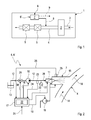
- a simplified illustrated motor vehicle 1 comprises an internal combustion engine 2, which receives fresh air via a fresh air system 3 and 4 exhaust combustion gases dissipates.
- exhaust purification devices 5 such. Ex. Catalysts and particulate filter can be arranged.
- the vehicle 1 is also equipped with a vehicle burner 6, with the aid of which a gas flow in the vehicle 1 can be heated.
- the vehicle burner 6 converts liquid fuel into a combustion chamber 7 with air.
- the combustion chamber 7 is connected to the exhaust system 4 on the exhaust side in accordance with an arrow 8 drawn by a solid line.
- the hot burner exhaust gases of the combustion chamber 7 of the exhaust system 4 can be supplied.
- the supply of these hot burner exhaust gases takes place within the exhaust system 4 with respect to a guided in the exhaust line 4 exhaust flow upstream of at least one heated by means of the vehicle's burner 6 exhaust gas purification device 5.
- a heating at least one exhaust gas purification device 5 are realized to an operating temperature, so that the respective exhaust gas cleaning device 5 can fulfill their cleaning function effectively.
- many catalysts have a light-off temperature from which they can develop their catalytic cleaning action.
- the vehicle burner 6 can be designed as a heating device 6 ', which can be operated independently of the internal combustion engine 2.
- Such a heater 6 ' may, for example.
- the burner exhaust gases generated in the combustion chamber 7 can then be used in accordance with an arrow 9 drawn with a broken line for heating a vehicle interior or for heating the internal combustion engine 2.
- the vehicle burner 6 (the following explanations also apply correspondingly to the heating device 6 ') comprises a fuel pump 10 with the aid of which a fuel can be conveyed to an actuatable injection nozzle 11, which can also be referred to as an injector 11.
- a fuel line 12 connects a fuel tank 13 with the suction side of the fuel pump 10 and the pressure side of the fuel pump 10 with the injection nozzle 11.
- the injection nozzle 11 serves to inject the fuel into the combustion chamber 7, which in the example of Fig. 2 exhaust side or outlet side is connected to the exhaust system 4.
- An exhaust gas flow flowing in the exhaust system 4 is in Fig. 2 indicated by arrows 14.
- Fig. 2 indicated by arrows 14.
- the vehicle burner 6 also comprises an air-conveying and / or air-regulating device 16, which may, for example, also be a pump or a fan. Likewise, it may be a compressed air reservoir or another air source.
- the combustion chamber 7 may be connected via a suitable valve device to an air control device of a compressed air system of the respective vehicle, for example an air suspension device or an air pressure brake system, or an exhaust gas turbocharger. With her, air, z. Ex. From the environment, are promoted to the combustion chamber 7. Furthermore, the vehicle burner 6, a controller 17, with the aid of the vehicle's burner 6 can be operated.
- the Controller 17 includes at least one, not shown here processor and is configured to determine a function of a supplied via a signal line 21, predetermined heating power, a fuel amount that is required to realize this heating power.
- the heating power may, for example, be predetermined by a control unit of the internal combustion engine 2 or by a request of a user.
- the controller can now determine a quantity of air that is required, in the combustion chamber 7 in conjunction with the determined amount of fuel, a fuel-air mixture depending on the determined fuel quantity and in dependence on an air ratio, which can also be specified or already fixed to produce that has the desired air ratio. Furthermore, the controller 17 is designed such that it determines a fuel pressure as a function of the determined air quantity.
- the fuel pressure has a significant influence on various injection parameters, such. For example, droplet size, droplet velocity, injection angle and the like.
- the determination of the fuel pressure is carried out specifically so that optimized injection parameters are achieved for the respective amount of air, which leads to a certain air velocity in an invariant geometry of the combustion chamber 7.
- the controller 17 may first determine a resulting air velocity depending on the amount of air and then determine the optimal injection pressure depending on the air speed.
- Said map 22 can basically be arbitrarily complex. In particular, depending on the heating power, it can supply the fuel quantity and / or the air quantity and / or the airspeed and / or the air ratio and / or the fuel pressure.
- the controller 17 is now configured such that it adjusts the predetermined heating power by the air conveying and / or air control device 16 for setting the determined air quantity, the fuel pump 10 for setting the determined fuel pressure and the injection nozzle 11 is actuated to set the determined amount of fuel.
- the injection nozzle 11 is opened more or less as a function of the fuel pressure or clocked in terms of opening duration and opening frequency.
- the vehicle burner 6 shown here also has at least one pressure sensor 23, which is coupled to the controller 17 via a signal line 24.
- the pressure sensor 23 can be arranged directly on the fuel line 12 or on the output side of the fuel pump 10 or on the input side of the injection nozzle 11 ,
- the controller 17 can now for adjusting the determined fuel pressure, which forms a target fuel pressure, the measured by means of the pressure sensor 23 fuel pressure, which forms an actual fuel pressure compare with the target fuel pressure to the function of the difference, the fuel pump 10th to regulate.
- the controller 17 controls the fuel pump 10 in response to a target-actual comparison of the fuel pressure.
- a proportional control may be appropriate.
- a PID control algorithm or another control algorithm may be used.
- the aim of the control is the realization of the lowest possible pressure fluctuations in the fuel line 12th
- the vehicle's burner 6 may be equipped with at least one temperature sensor 25, which is coupled to the controller 17 via a signal line 26.
- the temperature sensor 25 is for measuring a combustion chamber temperature provided.
- the temperature sensor 25 measures the temperature of a wall of the combustion chamber 7.
- the temperature sensor 25 can measure the temperature of the burner exhaust gases.
- the controller 17 can now take into account the current combustion chamber temperature in determining the required fuel pressure. This consideration can already be stored in the map 22. By taking into account the combustion chamber temperature, for example, the droplet size can be varied to optimize the evaporation of the injected fuel.
- the ambient temperature and / or fuel temperature can be taken into account in order, for example, to compensate for differences in viscosity via a suitably adapted fuel pressure.
- the droplet size correlates with the fuel pressure, whereby this correlation between droplet size and fuel pressure is taken into account when taking into account the combustion chamber temperature.
- the controller 17 may vary the delivery rate of the fuel pump 10 to adjust the desired fuel pressure.
- the fuel pump 10 may, for example, be configured as a rotary pump, z. Ex. In the form of a centrifugal pump or a gear pump or a rotary vane pump or the like. The controller 17 may change the speed in such a rotary pump to adjust the respective delivery rate and thus the fuel pressure.
- the fuel pump 10 may be configured as an oscillation pump, such as. For example, a piston pump or a diaphragm pump or the like. In such an oscillation pump, the controller may vary the stroke frequency and / or the stroke length and / or the stroke speed in order to set the respective desired delivery rate and thus the fuel pressure.
- the respective fuel pump 10 may have an adjustable by means of the controller 17 throttle and a bypass. The fuel pump 10 then operates stationary and By varying the throttle, the output side pressure can be adjusted. Unnecessary fuel flows back into the tank via the bypass or internally back to the suction side.
- a pressure accumulator 27 may be connected, whereby it is possible to compensate for pressure fluctuations in the fuel-carrying system or to dampen.
- the fuel line 12 is designed as an accumulator 28 at least in a section leading from the fuel pump 10 to the injection nozzle 11 is particularly advantageous.
- said line section 28 has a comparatively large volume.
- the controller 17 may be configured to take into account a compressive elasticity of the fuel system when adjusting the fuel pressure.
- Said fuel system extends from the fuel pump 10 to the injection nozzle 11 and thus comprises at least the associated portion of the fuel line 12 and in particular the pressure accumulator 27 and 28 respectively.
- the vehicle burner 6 is also equipped with a locking device 29, which may be, for example, a valve, in particular a solenoid valve.
- the blocking device 29 is coupled to the controller 17 via a control line 30. It is arranged in the fuel line 12 and that expedient upstream of the fuel pump 10. It is arranged as close to the fuel tank 13.
- the controller 17 actuates the locking device 29 when turning off the vehicle's burner 6 to block the fuel line 12. As a result, the fuel line 12 is locked when the vehicle's burner 6 is turned off.
- the fuel pump 10 may have a blocking function depending on their construction, so that it is possible to dispense with the additional locking device 29.
- the blocking function of the respective fuel pump 10 can be realized, for example, by a specific relative position of a delivery member of the fuel pump 10.
- the lock function When the lock function is activated, the fuel pump 10 blocks the fuel line 12.
- the controller 17 can now press the fuel pump 10 to activate the lock function when switching off the vehicle's burner 6. As a result, the fuel line 12 is locked when the vehicle burner 6 is turned off.
- the pressure ranges in which the fuel pressures can be varied as a function of the heating power of the vehicle's burner 6 depend in particular on the fuel pump 10 and can, for example, be in the range of 1 bar to 10 bar inclusive. Preference is given to a pressure range of from 2 bar up to and including 8 bar. Particularly advantageous may be a pressure range of from 3 bar to 6 bar inclusive.
- the combustion chamber 7 may have a primary combustion zone 31 and a secondary combustion zone 32.
- the injection nozzle 11 is attached to the combustion chamber 7 so as to inject the fuel exclusively into the primary combustion zone 31.
- the combustion chamber 7 has a porous, flow-through structure 33, which separates the primary combustion zone 31 from the secondary combustion zone 32.
- the structure 33 ensures that no liquid fuel enters the secondary combustion zone 32. However, it is well intended that vaporous fuel passes through structure 33 into secondary combustion zone 32. In that regard, the conversion of the fuel in the combustion chamber 7 into a pre-oxidation, which takes place in the primary combustion zone 31, and a post-oxidation, which takes place in the secondary combustion zone 32.
- the structure 33 is here preferably configured conical.
- an igniter 34 may be provided, for. Eg a glow plug or a spark plug or a piezo igniter.
- An arrow 35 indicates the supply of the liquid fuel to the injection nozzle 11.
- the conveyed by the air conveyor 16 air is at the in Fig. 3 split combustion chamber 7 divided into primary air 36 and secondary air 37, which is indicated by corresponding arrows.
- the primary air 36 is thereby fed to the primary combustion zone 31, while the secondary air 37 is supplied to the secondary combustion zone 32.
- the primary air 36 can flow into the primary combustion zone 31, in particular coaxially with the injection jet.
- the combustion chamber 7 has an inner tube 38, in which the two combustion zones 31, 32 and the structure 33 are arranged. Furthermore, the combustion chamber 7 has an outer tube 39, which is arranged coaxially to the inner tube 38, this encloses and thereby forms an annular space 40. Through this annular space 40, the secondary air flows into the secondary combustion zone 32. In this case, the secondary air 37 flows through a wall of the inner tube 38, which has corresponding wall openings for this purpose.
- the combustion chamber 7, in particular the secondary combustion zone 32 is corresponding Fig. 3 on the exhaust side or on the outlet side again connected to the exhaust system 4, in which an exhaust gas flow 14 prevails during operation of the internal combustion engine 2. Although in Fig. 3 a vertical arrangement of combustion chamber 7 and exhaust system 4 is shown, other angles may be provided to reduce the flow resistance.
Landscapes
- Engineering & Computer Science (AREA)
- Chemical & Material Sciences (AREA)
- Combustion & Propulsion (AREA)
- Mechanical Engineering (AREA)
- General Engineering & Computer Science (AREA)
- Air-Conditioning For Vehicles (AREA)
Abstract
Description
Die vorliegende Erfindung betrifft einen Fahrzeugbrenner zum Heizen einer Gasströmung in einem Kraftfahrzeug.The present invention relates to a vehicle burner for heating a gas flow in a motor vehicle.
Ein derartiger Fahrzeugbrenner kann bspw. zum Aufheizen einer Abgasreinigungseinrichtung verwendet werden, die in einer Abgasanlage einer Brennkraftmaschine des Kraftfahrzeugs angeordnet ist. Der Fahrzeugbrenner kann dabei zum Verkürzen der Zeit genutzt werden, die erforderlich ist, die jeweilige Abgasreinigungseinrichtung auf eine Mindestbetriebstemperatur oder Regenerationstemperatur zu bringen, ab der sie ihre Abgasreinigungsfunktion mit ausreichender Effektivität bzw. ihre Regeneration durchführen kann. Der Fahrzeugbrenner dient somit zur Reduzierung von Schadstoffemissionen. Ebenso ist es grundsätzlich möglich, einen derartigen Fahrzeugbrenner in einer fahrzeugseitigen, unabhängig von einer Brennkraftmaschine des Fahrzeugs betreibbaren Heizeinrichtung zu verwenden, bspw. in einer Standheizung bzw. in einem Zuheizer.Such a vehicle burner can be used, for example, for heating an exhaust gas purification device, which is arranged in an exhaust system of an internal combustion engine of the motor vehicle. The vehicle burner can be used to shorten the time required to bring the respective exhaust gas purification device to a minimum operating temperature or regeneration temperature, from which they can perform their emission control function with sufficient effectiveness or their regeneration. The vehicle burner thus serves to reduce pollutant emissions. Likewise, it is basically possible to use such a vehicle burner in a vehicle-side, independently of an internal combustion engine of the vehicle operable heater, for example. In a heater or in a heater.
Ein derartiger Fahrzeugbrenner kann eine Kraftstoffpumpe zum Fördern eines Kraftstoffs zu einer betätigbaren Einspritzdüse aufweisen. Mit Hilfe der betätigbaren Einspritzdüse, so genannter Injektor, kann Kraftstoff in eine Brennkammer eingespritzt werden. Ferner umfasst der Fahrzeugbrenner eine Luftförder- und/oder Luftregeleinrichtung, z. Bsp. ein Gebläse, eine Pumpe oder eine Druckquelle, zum Fördern von Luft zur Brennkammer. Eine zum Betreiben des Fahrzeugbrenners vorgesehene Steuerung ist auf geeignete Weise mit der Kraftstoffpumpe und mit der Luftförder- und/oder Luftregeleinrichtung sowie mit der Einspritzdüse gekoppelt. Zum Einstellen einer vorgegebenen Heizleistung betätigt die Steuerung die Einspritzdüse zum Einspritzen einer hierzu erforderlichen Kraftstoffmenge und die Luftförder- und/oder Luftregeleinrichtung zum Zuführen einer zugehörigen Luftmenge. Dabei ist es üblich, dass die Kraftstoffpumpe im Betrieb des Fahrzeugbrenners einen konstanten Kraftstoffdruck bereitstellt, wobei die in die Brennkammer eingespritzte Kraftstoffmengen mit Hilfe der Einspritzdüse einstellbar ist. Beispielsweise kann die Einspritzdüse unterschiedliche Öffnungsgrade aufweisen, die sich durch unterschiedliche Durchströmungswiderstände voneinander unterscheiden. Zusätzlich oder alternativ kann die Einspritzdüse getaktet betrieben werden, wobei insbesondere die Öffnungszeitdauer und die Taktfrequenz einstellbar sind, um nach Art einer Puls-Weiten Modulation die jeweilige Kraftstoffmenge einstellen zu können.Such a vehicle burner may include a fuel pump for delivering a fuel to an actuatable injector. Fuel can be injected into a combustion chamber with the aid of the actuatable injection nozzle, so-called injector. Furthermore, the vehicle burner comprises an air conveying and / or air regulating device, for. For example, a blower, a pump or a pressure source, for conveying air to the combustion chamber. A control provided for operating the vehicle's burner is suitably coupled to the fuel pump and to the air conveying and / or air regulating device as well as to the injection nozzle. To set a given heating power, the controller operates the injector to inject a thereto required amount of fuel and the Luftförder- and / or air control device for supplying an associated amount of air. It is customary here for the fuel pump to provide a constant fuel pressure during operation of the vehicle's burner, with the quantities of fuel injected into the combustion chamber being adjustable by means of the injection nozzle. For example, the injection nozzle may have different degrees of opening, which differ from each other by different flow resistance. Additionally or alternatively, the injection nozzle can be operated in a clocked manner, wherein in particular the opening time period and the clock frequency are adjustable in order to be able to set the respective amount of fuel in the manner of pulse-width modulation.
Die für die jeweilige Kraftstoffmenge erforderliche Luftmenge kann bspw. durch eine vorgegebene Luftzahl, so genannter Lambda-Wert oder Kraftstoff-LuftVerhältnis, bestimmt sein. Die Luftzahl wird üblicherweise so gewählt, dass sich möglichst niedrige Schadstoffemissionen ergeben.The amount of air required for the respective amount of fuel can be determined, for example, by a predetermined air ratio, so-called lambda value or air-fuel ratio. The air ratio is usually chosen so that the lowest possible pollutant emissions result.
Die vorliegende Erfindung beschäftigt sich mit dem Problem, für einen Fahrzeugbrenner der eingangs genannten Art eine verbesserte Ausführungsform anzugeben, die sich insbesondere dadurch auszeichnet, dass eine bessere Kraftstoffumsetzung realisierbar ist.The present invention is concerned with the problem of providing for a vehicle burner of the type mentioned in an improved embodiment, which is particularly characterized in that a better fuel conversion is feasible.
Dieses Problem wird durch den Gegenstand des unabhängigen Anspruchs gelöst. Vorteilhaft Ausführungsformen sind Gegenstand der abhängigen Ansprüche.This problem is solved by the subject matter of the independent claim. Advantageous embodiments are the subject of the dependent claims.
Die Erfindung beruht auf dem allgemeinen Gedanken, den Kraftstoffdruck in Abhängigkeit der geforderten Heizleistung zu modulieren. Die Erfindung nutzt hierbei die Erkenntnis, dass durch Verändern des Kraftstoffdrucks bzw. des Einspritzdrucks Einspritzparamenter, wie z. Bsp. Tröpfchengröße, Tröpfchengeschwindigkeit, Einspritzwinkel und Einspritzeindringtiefe, gezielt verändert werden können. Ferner nutzt die Erfindung die Erkenntnis, dass die von der Heizleistung abhängige Luftmenge in der Brennkammer zu stark unterschiedlichen Luftgeschwindigkeiten führt, was einen signifikanten Einfluss auf die Gemischbildung hat. Insbesondere beeinflusst die Luftgeschwindigkeit die Geometrie der Gemischbildungszone innerhalb der Brennkammer, die Durchdringung von Einspritzstrahl und Luftströmung, die Vermischung von Kraftstoff und Luft, die Verdampfung der eingespritzten Tröpfchen sowie allgemein eine Wechselwirkung zwischen eingespritzten Tröpfchen und Luft. Die erfindungsgemäß vorgeschlagene Anpassung des Kraftstoffdrucks bzw. des Einspritzdrucks an die aktuell gewünschte Brennerleistung berücksichtigt diese Zusammenhänge, so dass für jeden Lastfall und somit für jede Luftmenge die Kraftstoffeinspritzung bei einem hierfür besonders geeigneten Kraftstoffdruck realisierbar ist. Für die zusammenwirkenden Einspritzparameter, wie z. Bsp. Tröpfchengröße, Einspritzwinkel und Tröpfchengeschwindigkeit, kann somit für jeden Lastfall bzw. für jede Luftmenge ein Optimum bzw. ein optimierter Kompromiss bereitgestellt werden. Insgesamt ergibt sich dadurch eine verbesserte Umsetzung des Kraftstoffs in der Brennkammer. Dies führt zu einer signifikanten Verbesserung des Wirkungsgrads des Fahrzeugbrenners. Besonders vorteilhaft wirkt sich die Adaption des Einspritzdrucks bei niedrigeren Lasten aus. Es hat sich gezeigt, dass ein für große Lasten ausgelegter Kraftstoffdruck bei kleinen Luftmengen bzw. bei kleiner Luftgeschwindigkeit dazu führt, dass vergleichsweise viel flüssiger Kraftstoff an Wänden der Brennkammer auftrifft und dort nur unzureichend umgesetzt werden kann. Insbesondere kann der Kraftstoff verkoken. Durch die Adaption des Kraftstoffdrucks an die Heizleistung des Brenners können bspw. für kleinere Heizleistungen andere Kraftstoffdrücke eingestellt werden, wodurch effektiv vermieden werden kann, dass sich größere Kraftstoffmengen an Wänden der Brennkammer ansammeln.The invention is based on the general idea to modulate the fuel pressure as a function of the required heating power. The invention uses the knowledge that by changing the fuel pressure or the Injection pressure injection parameters, such. For example, droplet size, droplet velocity, injection angle and injection penetration can be selectively changed. Furthermore, the invention utilizes the knowledge that the amount of air dependent on the heating capacity in the combustion chamber leads to greatly different air velocities, which has a significant influence on the mixture formation. In particular, the air velocity affects the geometry of the mixture formation zone within the combustion chamber, the penetration of injection jet and air flow, the mixing of fuel and air, the vaporization of the injected droplets, and generally an interaction between injected droplets and air. The inventively proposed adjustment of the fuel pressure or the injection pressure to the currently desired burner performance takes into account these relationships, so that for each load case and thus for each air quantity, the fuel injection at a particularly suitable fuel pressure is feasible. For the cooperating injection parameters, such. For example, droplet size, injection angle and droplet speed, an optimum or an optimized compromise can thus be provided for each load case or for each air quantity. Overall, this results in an improved implementation of the fuel in the combustion chamber. This leads to a significant improvement in the efficiency of the vehicle's burner. Particularly advantageous is the adaptation of the injection pressure at lower loads. It has been found that a fuel pressure designed for large loads at small air quantities or at low air speeds results in comparatively large amounts of liquid fuel impinging on walls of the combustion chamber and being able to be converted there only inadequately. In particular, the fuel may coke. By adapting the fuel pressure to the heating power of the burner, for example, different fuel pressures can be set for smaller heat outputs, which can effectively prevent larger quantities of fuel from accumulating on walls of the combustion chamber.
Bei der Erfindung wird die Adaption des Kraftstoffdrucks an die Heizleistung dadurch realisiert, dass die Steuerung zunächst in Abhängigkeit der Heizleistung die hierfür erforderliche Kraftstoffmenge ermittelt, in Abhängigkeit der ermittelten Kraftstoffmenge sowie einer vorgegebenen Luftzahl die benötigte Luftmenge ermittelt und in Abhängigkeit der ermittelten Luftmenge bzw. der Kraftstoffmenge den dazu passenden Kraftstoffdruck ermittelt. Die Ermittlung der einzelnen Betriebsparameter kann dabei teilweise oder vollständig rechnerisch erfolgen. Ebenso können die Betriebsparameter teilweise oder vollständig aus Kennlinien oder Kennfeldern ermittelt werden. Dabei ist es insbesondere möglich, komplexe Kennfelder vorzusehen, aus denen in Abhängigkeit der Heizleistung zumindest zwei der Parameter Kraftstoffmenge, Luftmenge und Kraftstoffdruck auslesbar sind. Insbesondere ist auch ein Kennfeld denkbar, aus dem alle drei Betriebsparameter direkt auslesbar sind. Die Ermittlung der einzelnen Betriebsparameter erfolgt dann nicht schrittweise, sondern simultan.In the invention, the adaptation of the fuel pressure to the heating power is realized in that the controller initially determines the amount of fuel required for this purpose depending on the heating power, determined depending on the determined amount of fuel and a predetermined air ratio, the required amount of air and depending on the determined air quantity or Fuel quantity determines the appropriate fuel pressure. The determination of the individual operating parameters can be done partially or completely by calculation. Likewise, the operating parameters can be determined partially or completely from characteristic curves or characteristic diagrams. It is particularly possible to provide complex maps, from which at least two of the parameters amount of fuel, air quantity and fuel pressure can be read out depending on the heating power. In particular, a map is conceivable from which all three operating parameters are directly readable. The determination of the individual operating parameters is then not stepwise, but simultaneously.
Die Steuerung kann nun in Abhängigkeit der vorgegebenen Heizleistung die Kraftstoffpumpe zum Einstellen des ermittelten Kraftstoffdrucks, die Luftförder-und/oder Luftregeleinrichtung zum Einstellen der ermittelten Luftmenge und die Einspritzdüse zum Einstellen der ermittelten Kraftstoffmenge betätigen. Die Luftzahl kann dabei fest vorgegeben sein oder ebenfalls in Abhängigkeit der Heizleistung oder auch in Abhängigkeit der Kraftstoffmenge oder anderer Parameter ermittelt werden bzw. vorgegeben sein.The controller can now actuate the fuel pump for setting the determined fuel pressure, the air-conveying and / or air-regulating device for setting the determined air quantity and the injection nozzle for setting the determined fuel quantity as a function of the predetermined heating power. The air ratio can be fixed or can also be determined or predetermined as a function of the heating power or depending on the fuel quantity or other parameters.
Entsprechend einer besonders vorteilhaften Ausführungsform kann die Steuerung bei der Ermittlung des Kraftstoffdrucks die aktuelle Brennkammertemperatur berücksichtigen. Diese Weiterbildung beruht auf der Erkenntnis, dass die Brennkammertemperatur, die bspw. mittels eines entsprechenden Temperatursensors ermittelt werden kann, einen signifikanten Einfluss auf die Verdampfung der in die Brennkammer bzw. in die Luftströmung eingespritzten Kraftstofftröpfchen hat. Durch Berücksichtigen der Brennkammertemperatur bei der Ermittlung des Kraftstoffdrucks kann die Tröpfchengröße gezielt beeinflusst werden und somit an die Brennkammertemperatur angepasst werden. Auf diese Weise kann für jede Brennkammertemperatur eine geeignete Tröpfchengröße eingestellt werden, um die Verdampfung des Kraftstoffs zu optimieren.According to a particularly advantageous embodiment, the controller can take into account the current combustion chamber temperature when determining the fuel pressure. This refinement is based on the knowledge that the combustion chamber temperature, which can be determined, for example, by means of a corresponding temperature sensor, has a significant effect Influence on the evaporation of injected into the combustion chamber or in the air flow fuel droplets has. By considering the combustion chamber temperature when determining the fuel pressure, the droplet size can be influenced in a targeted manner and thus adapted to the combustion chamber temperature. In this way, a suitable droplet size can be set for each combustion chamber temperature to optimize the evaporation of the fuel.
Weitere wichtige Merkmale und Vorteile der Erfindung ergeben sich aus den Unteransprüchen, aus den Zeichnungen und aus der zugehörigen Figurenbeschreibung anhand der Zeichnungen.Other important features and advantages of the invention will become apparent from the dependent claims, from the drawings and from the associated figure description with reference to the drawings.
Es versteht sich, dass die vorstehend genannten und die nachstehend noch zu erläuternden Merkmale nicht nur in der jeweils angegebenen Kombination, sondern auch in anderen Kombinationen oder in Alleinstellung verwendbar sind, ohne den Rahmen der vorliegenden Erfindung zu verlassen.It is understood that the features mentioned above and those yet to be explained below can be used not only in the particular combination given, but also in other combinations or in isolation, without departing from the scope of the present invention.
Bevorzugte Ausführungsbeispiele der Erfindung sind in den Zeichnungen dargestellt und werden in der nachfolgenden Beschreibung näher erläutert, wobei sich gleiche Bezugszeichen auf gleiche oder ähnliche oder funktional gleiche Bauteile beziehen.Preferred embodiments of the invention are illustrated in the drawings and will be described in more detail in the following description, wherein like reference numerals refer to the same or similar or functionally identical components.
Es zeigen, jeweils schematisch,
- Fig. 1
- eine stark vereinfachte, schaltplanartige Prinzipdarstellung eines Kraftfahrzeugs, das mit einem Fahrzeugbrenner ausgestattet ist,
- Fig. 2
- eine stark vereinfachte, schaltplanartige Prinzipdarstellung des Fahrzeugbrenners,
- Fig. 3
- eine stark vereinfachte, schaltplanartige Prinzipdarstellung einer Brennkammer des Fahrzeugbrenners.
- Fig. 1
- a greatly simplified schematic diagram of a motor vehicle equipped with a vehicle burner,
- Fig. 2
- a greatly simplified schematic diagram of the vehicle's burner,
- Fig. 3
- a greatly simplified schematic diagram of a combustion chamber of the vehicle burner.
Entsprechend
Entsprechend
Die Steuerung 17 ist nun so ausgestaltet, dass sie die vorgegebene Heizleistung dadurch einstellt, dass sie die Luftförder- und/oder Luftregeleinrichtung 16 zum Einstellen der ermittelten Luftmenge, die Kraftstoffpumpe 10 zum Einstellen des ermittelten Kraftstoffdrucks und die Einspritzdüse 11 zum Einstellen der ermittelten Kraftstoffmenge betätigt. Dabei wird die Einspritzdüse 11 in Abhängigkeit des Kraftstoffdrucks mehr oder weniger geöffnet oder hinsichtlich Öffnungsdauer und Öffnungsfrequenz getaktet.The
Durch die Variation des Kraftstoffdrucks kann für jede Heizleistung eine optimierte Kraftstoffumsetzung realisiert werden.By varying the fuel pressure, an optimized fuel conversion can be realized for each heating power.
Der hier gezeigte Fahrzeugbrenner 6 weist außerdem zumindest einen Drucksensor 23 auf, der über eine Signalleitung 24 mit der Steuerung 17 gekoppelt ist. Mit Hilfe des Drucksensors 23 kann der Kraftstoffdruck in der Kraftstoffleitung 12 gemessen werden, und zwar zwischen der Kraftstoffpumpe 10 und der Einspritzdüse 11. Hierzu kann der Drucksensor 23 direkt an der Kraftstoffleitung 12 oder ausgangsseitig an der Kraftstoffpumpe 10 oder eingangsseitig an der Einspritzdüse 11 angeordnet sein. Die Steuerung 17 kann nun zum Einstellen des ermittelten Kraftstoffdrucks, der einen Soll-Kraftstoffdruck bildet, den mit Hilfe des Drucksensors 23 gemessenen Kraftstoffdruck, der einen Ist-Kraftstoffdruck bildet, mit dem Soll-Kraftstoffdruck vergleichen, um in Abhängigkeit der Differenz, die Kraftstoffpumpe 10 zu regeln. Mit anderen Worten, die Steuerung 17 regelt die Kraftstoffpumpe 10 in Abhängigkeit eines Soll-Ist-Vergleichs des Kraftstoffdrucks. Für die Druckregelung kann eine Proportionalregelung zweckmäßig sein. Ebenso kann ein PID-Regel-Algorithmus oder auch ein anderer Regelalgorithmus zur Anwendung kommen. Ziel der Regelung ist die Realisierung möglichst geringer Druckschwankungen in der Kraftstoffleitung 12.The
Zusätzlich oder alternativ kann der Fahrzeugbrenner 6 mit wenigstens einem Temperatursensor 25 ausgestattet sein, der über eine Signalleitung 26 mit der Steuerung 17 gekoppelt ist. Der Temperatursensor 25 ist dabei zum Messen einer Brennkammertemperatur vorgesehen. Beispielsweise misst der Temperatursensor 25 die Temperatur einer Wand der Brennkammer 7. Ebenso kann der Temperatursensor 25 die Temperatur der Brennerabgase messen. Die Steuerung 17 kann nun bei der Ermittlung des erforderlichen Kraftstoffdrucks die aktuelle Brennkammertemperatur berücksichtigen. Diese Berücksichtigung kann dabei bereits im Kennfeld 22 hinterlegt sein. Durch die Berücksichtigung der Brennkammertemperatur kann bspw. die Tröpfchengröße variiert werden, um die Verdampfung des eingespritzten Kraftstoffs zu optimieren. Zusätzlich oder alternativ kann die Umgebungstemperatur und/oder Kraftstofftemperatur berücksichtigt werden, um über einen entsprechend adaptierten Kraftstoffdruck z.B. Viskositätsunterschiede auszugleichen. Die Tröpfchengröße korreliert dabei mit dem Kraftstoffdruck, wobei diese Korrelation zwischen Tröpfchengröße und Kraftstoffdruck bei der Berücksichtigung der Brennkammertemperatur herangezogen wird.Additionally or alternatively, the vehicle's
Die Steuerung 17 kann die Förderleistung der Kraftstoffpumpe 10 verändern, um den jeweils gewünschten Kraftstoffdruck einzustellen. Die Kraftstoffpumpe 10 kann bspw. als Rotationspumpe ausgestaltet sein, z. Bsp. in Form einer Kreiselpumpe oder einer Zahnradpumpe oder einer Drehschieberpumpe oder dergleichen. Die Steuerung 17 kann bei einer solchen Rotationspumpe die Drehzahl verändern, um die jeweilige Förderleistung und somit den Kraftstoffdruck einzustellen. Alternativ kann die Kraftstoffpumpe 10 auch als Oszillationspumpe ausgestaltet sein, wie z. Bsp. eine Kolbenpumpe oder eine Membranpumpe oder dergleichen. Die Steuerung kann bei einer solchen Oszillationspumpe die Hubfrequenz und/oder die Hublänge und/oder die Hubgeschwindigkeit variieren, um die jeweils gewünschte Förderleistung und somit den Kraftstoffdruck einzustellen. Alternativ kann die jeweilige Kraftstoffpumpe 10 eine mit Hilfe der Steuerung 17 einstellbare Drossel sowie einen Bypass aufweisen. Die Kraftstoffpumpe 10 arbeitet dann stationär und durch Variieren der Drossel kann der ausgangsseitige Druck eingestellt werden. Nicht benötigter Kraftstoff fließt über den Bypass zurück in den Tank oder intern zurück zur Saugseite.The
An die Kraftstoffleitung 12 kann gemäß der hier gezeigten Ausführungsform ein Druckspeicher 27 angeschlossen sein, wodurch es möglich ist, Druckschwankungen im kraftstoffführenden System auszugleichen bzw. zu dämpfen. Besonders vorteilhaft ist dabei eine Ausführungsform, bei welcher die Kraftstoffleitung 12 zumindest in einem von der Kraftstoffpumpe 10 zur Einspritzdüse 11 führenden Abschnitt als Druckspeicher 28 ausgestaltet ist. Beispielsweise besitzt besagter Leitungsabschnitt 28 ein vergleichsweise großes Volumen.To the
Entsprechend einer vorteilhaften Ausführungsform kann die Steuerung 17 so ausgestaltet sein, dass sie beim Einstellen des Kraftstoffdrucks eine Druckelastizität des Kraftstoffsystems berücksichtigt. Besagtes Kraftstoffsystem erstreckt sich dabei von der Kraftstoffpumpe 10 bis zur Einspritzdüse 11 und umfasst somit zumindest den zugehörigen Abschnitt der Kraftstoffleitung 12 und insbesondere den Druckspeicher 27 bzw. 28.According to an advantageous embodiment, the
Im Beispiel der
Die Druckbereiche, in denen die Kraftstoffdrücke abhängig von der Heizleistung des Fahrzeugbrenners 6 variiert werden können, hängen insbesondere von der Kraftstoffpumpe 10 ab und können bspw. in einem Bereich von einschließlich 1 bar bis einschließlich 10 bar liegen. Bevorzugt ist dabei ein Druckbereich von einschließlich 2 bar bis einschließlich 8 bar. Besonders vorteilhaft kann ein Druckbereich von einschließlich 3 bar bis einschließlich 6 bar sein.The pressure ranges in which the fuel pressures can be varied as a function of the heating power of the vehicle's
Entsprechend
Die Brennkammer 7 weist ein Innenrohr 38 auf, in dem die beiden Brennzonen 31, 32 sowie die Struktur 33 angeordnet sind. Ferner weist die Brennkammer 7 ein Außenrohr 39 auf, das koaxial zum Innenrohr 38 angeordnet ist, dieses umschließt und dabei einen Ringraum 40 ausbildet. Durch diesen Ringraum 40 strömt die Sekundärluft in die Sekundärbrennzone 32. Dabei durchströmt die Sekundärluft 37 eine Wand des Innenrohrs 38, das zu diesem Zweck entsprechende Wandöffnungen aufweist. Die Brennkammer 7, insbesondere die Sekundärbrennzone 32, ist entsprechend
Claims (15)
dadurch gekennzeichnet,
characterized,
dadurch gekennzeichnet,
characterized,
dadurch gekennzeichnet,
characterized,
dadurch gekennzeichnet,
dass die Steuerung (17) zum Einstellen des Kraftstoffdrucks eine Förderleistung der Kraftstoffpumpe (10) verändert.Vehicle burner according to one of claims 1 to 4,
characterized,
in that the controller (17) for adjusting the fuel pressure changes a delivery rate of the fuel pump (10).
dadurch gekennzeichnet,
characterized,
dadurch gekennzeichnet,
characterized,
dadurch gekennzeichnet,
dass die Steuerung (17) beim Einstellen des Kraftstoffdrucks eine Druckelastizität des sich von der Kraftstoffpumpe (10) zur Einspritzdüse (11) erstreckenden Kraftstoffsystems berücksichtigt.Vehicle burner according to one of claims 1 to 7,
characterized,
that the controller (17) when adjusting the fuel pressure, a compression elasticity of itself from the fuel pump (10) to the injection nozzle extending (11) the fuel system considered.
dadurch gekennzeichnet,
characterized,
dadurch gekennzeichnet,
characterized,
dadurch gekennzeichnet,
dass die Kraftstoffpumpe (10) und die Steuerung (17) so ausgestaltet sind, dass der Kraftstoffdruck in einem Bereich von einschließlich 1 bar bis einschließlich 10 bar oder von einschließlich 2 bar bis einschließlich 8 bar oder von einschließlich 3 bar bis einschließlich 6 bar einstellbar ist.Vehicle burner according to one of claims 1 to 10,
characterized,
in that the fuel pump (10) and the controller (17) are designed such that the fuel pressure ranges from 1 bar to 10 inclusive bar or from 2 bar up to and including 8 bar or from 3 bar up to and including 6 bar is adjustable.
dadurch gekennzeichnet,
characterized,
dadurch gekennzeichnet,
characterized,
dadurch gekennzeichnet,
dass die Brennkammer (7) zum Aufheizen wenigstens einer Abgasreinigungseinrichtung (5) abgasseitig an eine Abgasanlage (4) einer Brennkraftmaschine (2) angeschlossen ist.Vehicle burner according to one of claims 1 to 13,
characterized,
in that the combustion chamber (7) for heating at least one exhaust gas purification device (5) is connected on the exhaust side to an exhaust system (4) of an internal combustion engine (2).
dadurch gekennzeichnet,
dass die Brennkammer (7) in einer unabhängig von einer Brennkraftmaschine (2) des Fahrzeugs (1) betreibbaren Heizeinrichtung (6'), z. Bsp. Standheizung und/oder Zuheizer, des Fahrzeugs (1) angeordnet ist.Vehicle burner according to one of claims 1 to 13,
characterized,
in that the combustion chamber (7) can be operated in a heating device (6 ') which can be operated independently of an internal combustion engine (2) of the vehicle (1), z. Ex. Auxiliary heater and / or auxiliary heater, the vehicle (1) is arranged.
Applications Claiming Priority (1)
| Application Number | Priority Date | Filing Date | Title |
|---|---|---|---|
| DE102008063990A DE102008063990A1 (en) | 2008-12-19 | 2008-12-19 | vehicle burner |
Publications (3)
| Publication Number | Publication Date |
|---|---|
| EP2199678A2 true EP2199678A2 (en) | 2010-06-23 |
| EP2199678A3 EP2199678A3 (en) | 2011-12-14 |
| EP2199678B1 EP2199678B1 (en) | 2016-10-19 |
Family
ID=42026180
Family Applications (1)
| Application Number | Title | Priority Date | Filing Date |
|---|---|---|---|
| EP09176832.5A Active EP2199678B1 (en) | 2008-12-19 | 2009-11-24 | Burner for a vehicle heating device |
Country Status (4)
| Country | Link |
|---|---|
| US (1) | US8695569B2 (en) |
| EP (1) | EP2199678B1 (en) |
| CN (1) | CN101749728A (en) |
| DE (1) | DE102008063990A1 (en) |
Cited By (4)
| Publication number | Priority date | Publication date | Assignee | Title |
|---|---|---|---|---|
| DE102012110103A1 (en) * | 2012-10-23 | 2014-04-24 | Spheros Gmbh | Liquid fuel heater |
| RU203661U1 (en) * | 2020-12-16 | 2021-04-15 | Публичное акционерное общество "КАМАЗ" | Preheater fuel tank filling system |
| EP4202193A1 (en) * | 2021-12-21 | 2023-06-28 | Marelli Europe S.p.A. | Heating device for an exhaust system of an internal combustion engine and relative control method |
| WO2023237294A1 (en) * | 2022-06-08 | 2023-12-14 | Robert Bosch Gmbh | Burner for an exhaust-gas aftertreatment system, exhaust-gas aftertreatment system for an internal combustion engine |
Families Citing this family (25)
| Publication number | Priority date | Publication date | Assignee | Title |
|---|---|---|---|---|
| FR2946098A1 (en) * | 2009-05-26 | 2010-12-03 | Patrick Wathieu | METHOD OF OPERATING AN EXPLOSION ENGINE AND EXPLOSION ENGINE OPERATING ACCORDING TO SAID METHOD. |
| DE102010038865A1 (en) * | 2010-08-04 | 2012-02-09 | Robert Bosch Gmbh | Burner with stable atomization at low back pressure |
| DE102011081309B3 (en) * | 2011-08-22 | 2012-09-27 | Bosch Emission Systems Gmbh & Co. Kg | Method for operating burner in exhaust system of internal combustion engine of motor vehicle, involves setting smaller burner power in region at which air-fuel ratio is greater than one so as to reduce thermal load of burner |
| ITBO20120128A1 (en) * | 2012-03-13 | 2013-09-14 | Riello Spa | COMBUSTION EQUIPMENT OF LIQUID FUELS AND ITS METHOD TO MODULATE THE POWER OF SUCH EQUIPMENT |
| EP2789915A1 (en) * | 2013-04-10 | 2014-10-15 | Alstom Technology Ltd | Method for operating a combustion chamber and combustion chamber |
| CN103675215B (en) * | 2013-12-24 | 2016-01-20 | 安徽省芜湖仪器仪表研究有限责任公司 | A kind of detection simulation system of oxygen sensor used in vehicle |
| DE102015220408A1 (en) * | 2015-10-20 | 2017-04-20 | Robert Bosch Gmbh | Method and device for heating a catalyst |
| CN105485680B (en) * | 2015-12-07 | 2018-11-20 | 湖南三一路面机械有限公司 | Burner and its control method and bituminous mixing plant |
| RU2642863C2 (en) * | 2016-07-08 | 2018-01-29 | Евгений Поликарпович Лебедев | Method for preparing liquid fuel for combustion and device for implementation |
| RU171963U1 (en) * | 2016-12-01 | 2017-06-22 | Публичное акционерное общество "КАМАЗ" | PRE-START HEATER FUEL SYSTEM |
| CN107023366A (en) * | 2017-05-26 | 2017-08-08 | 凯龙高科技股份有限公司 | A kind of control of burner dpf regeneration and diagnostic system for non-rice habitats agricultural machinery |
| CN107091135A (en) * | 2017-05-26 | 2017-08-25 | 凯龙高科技股份有限公司 | Meet the diesel engine premixed combustion device after-treatment system of PM emission controls |
| DE102017007681A1 (en) * | 2017-08-09 | 2019-02-14 | Robert Zink | Gas burners with improved properties |
| CN107387288A (en) * | 2017-09-04 | 2017-11-24 | 郑州振资汽车配件有限公司 | Parking heater |
| CN108954318B (en) * | 2018-08-29 | 2023-08-25 | 国电环境保护研究院有限公司 | Analysis system and analysis method for axial staged premixed combustion characteristics of gas fuel |
| KR102613522B1 (en) | 2019-02-18 | 2023-12-13 | 삼성전자주식회사 | A foldable electronic device including a bezel sag preventing structure |
| CN111043623B (en) * | 2019-12-30 | 2021-07-30 | 哈尔滨工业大学 | Method for preventing combustion chamber from generating resonance based on closed-loop negative feedback regulation of electric field influencing flame root |
| CN112065538B (en) * | 2020-09-16 | 2022-07-15 | 孙金辉 | Thermal management device of diesel engine aftertreatment system |
| EP4019748B1 (en) * | 2020-12-23 | 2023-12-06 | Marelli Europe S.p.A. | Heating device for an exhaust system of an internal combustion engine |
| DE102021103123A1 (en) | 2021-02-10 | 2022-08-11 | Volkswagen Aktiengesellschaft | Method and device for enabling a cold run in vehicles with monovalent gaseous fuel supply by means of an auxiliary heating device supplied with pressurized air |
| IT202100017258A1 (en) * | 2021-06-30 | 2022-12-30 | Marelli Europe Spa | METHOD OF CHECKING A BURNER FOR AN EXHAUST SYSTEM OF AN INTERNAL COMBUSTION ENGINE |
| IT202100017255A1 (en) * | 2021-06-30 | 2022-12-30 | Marelli Europe Spa | METHOD OF CHECKING A BURNER FOR AN EXHAUST SYSTEM OF AN INTERNAL COMBUSTION ENGINE |
| US11506136B1 (en) * | 2021-07-22 | 2022-11-22 | Tenneco Automotive Operating Company Inc. | Selective catalytic reduction catalyst pre-heating and exhaust burner air control |
| IT202100021665A1 (en) * | 2021-08-10 | 2023-02-10 | Marelli Europe Spa | METHOD OF TESTING AN EXHAUST GAS AFTER-TREATMENT SYSTEM FOR AN EXHAUST GAS EXHAUST SYSTEM OF AN INTERNAL COMBUSTION ENGINE |
| DE102022211127A1 (en) * | 2022-10-20 | 2024-04-25 | Robert Bosch Gesellschaft mit beschränkter Haftung | Method, computing unit and computer program for operating a burner |
Citations (8)
| Publication number | Priority date | Publication date | Assignee | Title |
|---|---|---|---|---|
| DE4216523A1 (en) * | 1992-05-19 | 1993-12-02 | Webasto Thermosysteme Gmbh | Fuelled heater with turbulence nozzle - has fuel-absorbent body on combustion-chamber rear wall extending nearly to nozzle outlet |
| DE4447286A1 (en) * | 1994-12-30 | 1996-07-04 | Eberspaecher J | Vehicle heater with controlled combustion air fan |
| WO2002063266A1 (en) * | 2001-02-02 | 2002-08-15 | Endress+Hauser Gmbh + Co. Kg. | Differential pressure sensor with overload protection |
| WO2002066809A2 (en) * | 2001-02-02 | 2002-08-29 | Siemens Aktiengesellschaft | Sensor mounted in an injection line leading to an injection valve in a direct-injection internal combustion engine |
| EP1378710A2 (en) * | 2002-07-05 | 2004-01-07 | J. Eberspächer GmbH & Co. KG | Pressure regulator for an atomizing burner of a vehicle heater |
| DE10240208A1 (en) * | 2002-06-25 | 2004-01-22 | Webasto Thermosysteme International Gmbh | Heater comprises a gas bubble detector and an associated control unit capable of determining the temperature, type and/or flow velocity of the fuel in the fuel line |
| EP1591154A1 (en) * | 2004-04-26 | 2005-11-02 | J. Eberspächer GmbH Co. KG | Evaporator for the realization of a hydrocarbon vapour/composite material mixtures, especially for a reformer of a fuel cell. |
| WO2008080183A1 (en) * | 2007-01-04 | 2008-07-10 | Glueck Christoph | Method for burning liquid fuels |
Family Cites Families (34)
| Publication number | Priority date | Publication date | Assignee | Title |
|---|---|---|---|---|
| DE1074920B (en) * | 1955-07-07 | 1960-02-04 | Ing habil Fritz A F Schmidt Murnau Dr (Obb) | Method and device for regulating gas turbine combustion chambers with subdivided combustion and several pressure levels |
| DE3311603C2 (en) * | 1983-03-30 | 1986-11-13 | Walter 8702 Leinach Lang | Method for controlling the combustion of, in particular, heating oil in a heating system and burners for carrying out the method |
| DE3734197A1 (en) * | 1987-10-09 | 1989-04-20 | Bosch Gmbh Robert | DEVICE FOR REMOVING SOLID PARTICLES, IN PARTICULAR CARBON PARTICLES, FROM THE EXHAUST GAS FROM AN INTERNAL COMBUSTION ENGINE |
| US5253475A (en) * | 1992-06-22 | 1993-10-19 | General Motors Corporation | Combustion detection |
| US5339630A (en) * | 1992-08-28 | 1994-08-23 | General Motors Corporation | Exhaust burner catalyst preheater |
| US5320523A (en) * | 1992-08-28 | 1994-06-14 | General Motors Corporation | Burner for heating gas stream |
| US5284016A (en) * | 1992-08-28 | 1994-02-08 | General Motors Corporation | Exhaust gas burner reactor |
| US5277025A (en) * | 1992-08-31 | 1994-01-11 | General Motors Corporation | Exhaust burner control |
| US5419121A (en) * | 1993-04-16 | 1995-05-30 | Engelhard Corporation | Method and apparatus for reduction of pollutants emitted from automotive engines by flame incineration |
| JP3282944B2 (en) * | 1994-07-18 | 2002-05-20 | トヨタ自動車株式会社 | Low NOx burner |
| DE4435196C1 (en) * | 1994-09-30 | 1995-10-12 | Siemens Ag | Burner system efficiency checking method for vehicle exhaust catalytic converter warm=up |
| ES2151273T3 (en) * | 1996-04-20 | 2000-12-16 | Al Halbouni Ahmad | COMBUSTION CHAMBER WITH A BURNER DEVICE AND OPERATION PROCEDURE OF A COMBUSTION CHAMBER. |
| DE69920601T2 (en) * | 1998-02-27 | 2006-03-09 | Stanadyne Corp., Windsor | FUEL SUPPLY PUMP FOR FUEL INJECTION PUMP |
| WO2001033141A1 (en) * | 1999-11-02 | 2001-05-10 | Ebara Corporation | Combustor for exhaust gas treatment |
| JP3920526B2 (en) * | 2000-03-08 | 2007-05-30 | トヨタ自動車株式会社 | Spark ignition stratified combustion internal combustion engine |
| DE10059427A1 (en) * | 2000-11-30 | 2002-06-06 | Bosch Gmbh Robert | Exhaust gas aftertreatment device and method |
| JP3899884B2 (en) * | 2001-10-04 | 2007-03-28 | トヨタ自動車株式会社 | Exhaust gas purification device for internal combustion engine |
| DE10151688A1 (en) * | 2001-10-19 | 2003-04-30 | Bosch Gmbh Robert | Valve for controlling liquids |
| DE10304489B4 (en) * | 2002-04-11 | 2014-07-31 | Das Environmental Expert Gmbh | Device for purifying exhaust gases containing fluorine-containing compounds in a low-nitrogen-oxide combustion reactor |
| JP2004324587A (en) * | 2003-04-25 | 2004-11-18 | Mitsubishi Fuso Truck & Bus Corp | Emission control device of internal combustion engine |
| JP3960283B2 (en) * | 2003-09-01 | 2007-08-15 | トヨタ自動車株式会社 | Fuel injection device for internal combustion engine |
| DE10354232A1 (en) * | 2003-11-20 | 2005-06-30 | J. Eberspächer GmbH & Co. KG | Exhaust gas treatment system for an internal combustion engine, in particular a diesel internal combustion engine, and method for operating an exhaust gas treatment system for an internal combustion engine |
| JP2005273577A (en) * | 2004-03-25 | 2005-10-06 | Nissan Diesel Motor Co Ltd | Liquefied gas fuel supply device |
| DE102004061400B4 (en) * | 2004-12-21 | 2012-12-20 | Umicore Ag & Co. Kg | Method for generating a stream of hot combustion gases with adjustable temperature, apparatus for carrying out the method and use of the combustion gases for the targeted aging of catalysts |
| KR100542803B1 (en) * | 2005-06-22 | 2006-01-11 | 한국기계연구원 | Burner for regeneration of diesel particulate filter |
| US7503168B2 (en) * | 2006-03-24 | 2009-03-17 | Cumming Filtration Ip, Inc | Apparatus, system, and method for particulate filter regeneration |
| US7552584B2 (en) * | 2006-03-31 | 2009-06-30 | Caterpillar Inc. | Common engine and exhaust treatment fuel system |
| DE102006050560A1 (en) * | 2006-06-03 | 2007-12-06 | Bayerische Motoren Werke Ag | Operating method for a system of a reformer and a catalytic exhaust aftertreatment device |
| US7849682B2 (en) * | 2006-08-31 | 2010-12-14 | Caterpillar Inc | Exhaust treatment device having a fuel powered burner |
| DE102006060299A1 (en) * | 2006-12-20 | 2008-06-26 | Robert Bosch Gmbh | Method for operating a fuel system for an internal combustion engine |
| JP4951380B2 (en) * | 2007-03-26 | 2012-06-13 | 日立オートモティブシステムズ株式会社 | High pressure fuel system controller |
| US7591648B2 (en) * | 2007-09-13 | 2009-09-22 | Maxon Corporation | Burner apparatus |
| US20120073268A1 (en) * | 2010-09-29 | 2012-03-29 | Navin Khadiya | Fuel-fired burner for no2 based regeneration |
| US8438838B2 (en) * | 2010-10-11 | 2013-05-14 | Faurecia Emissions Control Technologies | Fuel-fired burner and heat exchanger system for heating a NOx reducing agent supply tank |
-
2008
- 2008-12-19 DE DE102008063990A patent/DE102008063990A1/en not_active Ceased
-
2009
- 2009-11-24 EP EP09176832.5A patent/EP2199678B1/en active Active
- 2009-12-17 US US12/640,483 patent/US8695569B2/en active Active
- 2009-12-21 CN CN200910247076A patent/CN101749728A/en active Pending
Patent Citations (8)
| Publication number | Priority date | Publication date | Assignee | Title |
|---|---|---|---|---|
| DE4216523A1 (en) * | 1992-05-19 | 1993-12-02 | Webasto Thermosysteme Gmbh | Fuelled heater with turbulence nozzle - has fuel-absorbent body on combustion-chamber rear wall extending nearly to nozzle outlet |
| DE4447286A1 (en) * | 1994-12-30 | 1996-07-04 | Eberspaecher J | Vehicle heater with controlled combustion air fan |
| WO2002063266A1 (en) * | 2001-02-02 | 2002-08-15 | Endress+Hauser Gmbh + Co. Kg. | Differential pressure sensor with overload protection |
| WO2002066809A2 (en) * | 2001-02-02 | 2002-08-29 | Siemens Aktiengesellschaft | Sensor mounted in an injection line leading to an injection valve in a direct-injection internal combustion engine |
| DE10240208A1 (en) * | 2002-06-25 | 2004-01-22 | Webasto Thermosysteme International Gmbh | Heater comprises a gas bubble detector and an associated control unit capable of determining the temperature, type and/or flow velocity of the fuel in the fuel line |
| EP1378710A2 (en) * | 2002-07-05 | 2004-01-07 | J. Eberspächer GmbH & Co. KG | Pressure regulator for an atomizing burner of a vehicle heater |
| EP1591154A1 (en) * | 2004-04-26 | 2005-11-02 | J. Eberspächer GmbH Co. KG | Evaporator for the realization of a hydrocarbon vapour/composite material mixtures, especially for a reformer of a fuel cell. |
| WO2008080183A1 (en) * | 2007-01-04 | 2008-07-10 | Glueck Christoph | Method for burning liquid fuels |
Cited By (5)
| Publication number | Priority date | Publication date | Assignee | Title |
|---|---|---|---|---|
| DE102012110103A1 (en) * | 2012-10-23 | 2014-04-24 | Spheros Gmbh | Liquid fuel heater |
| WO2014063845A1 (en) * | 2012-10-23 | 2014-05-01 | Spheros Gmbh | Heating device operated with liquid fuel |
| RU203661U1 (en) * | 2020-12-16 | 2021-04-15 | Публичное акционерное общество "КАМАЗ" | Preheater fuel tank filling system |
| EP4202193A1 (en) * | 2021-12-21 | 2023-06-28 | Marelli Europe S.p.A. | Heating device for an exhaust system of an internal combustion engine and relative control method |
| WO2023237294A1 (en) * | 2022-06-08 | 2023-12-14 | Robert Bosch Gmbh | Burner for an exhaust-gas aftertreatment system, exhaust-gas aftertreatment system for an internal combustion engine |
Also Published As
| Publication number | Publication date |
|---|---|
| EP2199678B1 (en) | 2016-10-19 |
| US8695569B2 (en) | 2014-04-15 |
| CN101749728A (en) | 2010-06-23 |
| EP2199678A3 (en) | 2011-12-14 |
| DE102008063990A1 (en) | 2010-06-24 |
| US20100154745A1 (en) | 2010-06-24 |
Similar Documents
| Publication | Publication Date | Title |
|---|---|---|
| EP2199678B1 (en) | Burner for a vehicle heating device | |
| EP0599060B1 (en) | Burner system for exhaust gas detoxification or purification for an internal combustion engine | |
| EP1582709B1 (en) | Method of regeneration for a particulate filter and an exhaust gas system with a particulate filter | |
| EP1752632B1 (en) | Exhaust gas purification device and corresponding method | |
| DE112007002006T5 (en) | Exhaust gas treatment device with a fuel-driven burner | |
| DE102005054733A1 (en) | Burner for catalyst heating with controlled or regulated fuel supply | |
| WO2007079832A1 (en) | Exhaust gas installation for a motor vehicle and method for regenerating a particle filter in an exhaust gas installation of a motor vehicle | |
| DE1933514A1 (en) | Fuel injection system for internal combustion engines | |
| WO2014114443A1 (en) | Method for operating a drive mechanism, and corresponding drive mechanism | |
| EP3408528B1 (en) | Emulsifying system and emulsifying method | |
| WO2014131498A1 (en) | Method and device for operating a diesel engine with emulsion fuels of variable composition | |
| EP0599061B1 (en) | Method to purify the exhaust gas of an internal combustion engine | |
| DE4411959A1 (en) | Heater for intake air in diesel engines | |
| DE2610690A1 (en) | COMBUSTION MACHINE WITH A DEVICE FOR SUPPLYING FUEL | |
| DE102004062208A1 (en) | vehicle exhaust gas cleaning system regeneration involves driving dosing element depending on line pressure to feed oxidisable liquid to heating chamber, evaporating liquid with heating element, feeding vapor into gas before cleaning system | |
| EP3530504B1 (en) | Method for operating a fuel-driven vehicle heating device | |
| WO2008012005A1 (en) | Spark-ignited internal combustion engine for gaseous fuels, and method for the operation of such an internal combustion engine | |
| EP0816673B1 (en) | Method of operating a flame starting system for internal combustion engine and flame starting system for internal combustion engine | |
| DE102013111546B9 (en) | Method for adjusting a mobile, fuel-powered heater | |
| WO2012089390A1 (en) | Method for controlling measures for heating a catalytic converter in an internal combustion engine comprising two injectors per cylinder | |
| WO2013017126A2 (en) | Vehicle heating device for operation with a plurality of fuel types | |
| DE102009026266A1 (en) | Mobile heating device has chamber for reaction of fuel with combustion air to provide thermal heat, where fuel supply is provided for supplying liquid fuel to an evaporator area for evaporating the liquid fuel | |
| WO1996006305A1 (en) | Heater for a vehicle powered by an internal-combustion engine | |
| DE4416014A1 (en) | Improving cleaning of exhaust gases from internal combustion engines | |
| WO2016113045A1 (en) | Exhaust gas aftertreatment system |
Legal Events
| Date | Code | Title | Description |
|---|---|---|---|
| PUAI | Public reference made under article 153(3) epc to a published international application that has entered the european phase |
Free format text: ORIGINAL CODE: 0009012 |
|
| AK | Designated contracting states |
Kind code of ref document: A2 Designated state(s): AT BE BG CH CY CZ DE DK EE ES FI FR GB GR HR HU IE IS IT LI LT LU LV MC MK MT NL NO PL PT RO SE SI SK SM TR |
|
| PUAL | Search report despatched |
Free format text: ORIGINAL CODE: 0009013 |
|
| AK | Designated contracting states |
Kind code of ref document: A3 Designated state(s): AT BE BG CH CY CZ DE DK EE ES FI FR GB GR HR HU IE IS IT LI LT LU LV MC MK MT NL NO PL PT RO SE SI SK SM TR |
|
| RIC1 | Information provided on ipc code assigned before grant |
Ipc: F23D 99/00 20100101ALI20111110BHEP Ipc: F23D 11/24 20060101ALI20111110BHEP Ipc: F23N 1/02 20060101AFI20111110BHEP Ipc: F23K 5/04 20060101ALI20111110BHEP |
|
| 17P | Request for examination filed |
Effective date: 20120613 |
|
| RAP1 | Party data changed (applicant data changed or rights of an application transferred) |
Owner name: BOSCH EMISSION SYSTEMS GMBH & CO. KG |
|
| RAP1 | Party data changed (applicant data changed or rights of an application transferred) |
Owner name: ROBERT BOSCH GMBH |
|
| REG | Reference to a national code |
Ref country code: DE Ref legal event code: R079 Ref document number: 502009013244 Country of ref document: DE Free format text: PREVIOUS MAIN CLASS: F23N0001020000 Ipc: F01N0009000000 |
|
| RIC1 | Information provided on ipc code assigned before grant |
Ipc: F23K 5/04 20060101ALI20160511BHEP Ipc: F23D 11/24 20060101ALI20160511BHEP Ipc: F23N 1/02 20060101ALI20160511BHEP Ipc: F23D 99/00 20100101ALI20160511BHEP Ipc: F01N 9/00 20060101AFI20160511BHEP |
|
| GRAP | Despatch of communication of intention to grant a patent |
Free format text: ORIGINAL CODE: EPIDOSNIGR1 |
|
| INTG | Intention to grant announced |
Effective date: 20160718 |
|
| GRAS | Grant fee paid |
Free format text: ORIGINAL CODE: EPIDOSNIGR3 |
|
| GRAA | (expected) grant |
Free format text: ORIGINAL CODE: 0009210 |
|
| AK | Designated contracting states |
Kind code of ref document: B1 Designated state(s): AT BE BG CH CY CZ DE DK EE ES FI FR GB GR HR HU IE IS IT LI LT LU LV MC MK MT NL NO PL PT RO SE SI SK SM TR |
|
| REG | Reference to a national code |
Ref country code: GB Ref legal event code: FG4D Free format text: NOT ENGLISH |
|
| REG | Reference to a national code |
Ref country code: CH Ref legal event code: EP |
|
| REG | Reference to a national code |
Ref country code: AT Ref legal event code: REF Ref document number: 838554 Country of ref document: AT Kind code of ref document: T Effective date: 20161115 |
|
| REG | Reference to a national code |
Ref country code: IE Ref legal event code: FG4D Free format text: LANGUAGE OF EP DOCUMENT: GERMAN |
|
| REG | Reference to a national code |
Ref country code: FR Ref legal event code: PLFP Year of fee payment: 8 |
|
| REG | Reference to a national code |
Ref country code: DE Ref legal event code: R096 Ref document number: 502009013244 Country of ref document: DE |
|
| REG | Reference to a national code |
Ref country code: NL Ref legal event code: MP Effective date: 20161019 |
|
| REG | Reference to a national code |
Ref country code: LT Ref legal event code: MG4D |
|
| PG25 | Lapsed in a contracting state [announced via postgrant information from national office to epo] |
Ref country code: LV Free format text: LAPSE BECAUSE OF FAILURE TO SUBMIT A TRANSLATION OF THE DESCRIPTION OR TO PAY THE FEE WITHIN THE PRESCRIBED TIME-LIMIT Effective date: 20161019 Ref country code: BE Free format text: LAPSE BECAUSE OF NON-PAYMENT OF DUE FEES Effective date: 20161130 |
|
| PG25 | Lapsed in a contracting state [announced via postgrant information from national office to epo] |
Ref country code: SE Free format text: LAPSE BECAUSE OF FAILURE TO SUBMIT A TRANSLATION OF THE DESCRIPTION OR TO PAY THE FEE WITHIN THE PRESCRIBED TIME-LIMIT Effective date: 20161019 Ref country code: LT Free format text: LAPSE BECAUSE OF FAILURE TO SUBMIT A TRANSLATION OF THE DESCRIPTION OR TO PAY THE FEE WITHIN THE PRESCRIBED TIME-LIMIT Effective date: 20161019 Ref country code: NO Free format text: LAPSE BECAUSE OF FAILURE TO SUBMIT A TRANSLATION OF THE DESCRIPTION OR TO PAY THE FEE WITHIN THE PRESCRIBED TIME-LIMIT Effective date: 20170119 Ref country code: GR Free format text: LAPSE BECAUSE OF FAILURE TO SUBMIT A TRANSLATION OF THE DESCRIPTION OR TO PAY THE FEE WITHIN THE PRESCRIBED TIME-LIMIT Effective date: 20170120 |
|
| PG25 | Lapsed in a contracting state [announced via postgrant information from national office to epo] |
Ref country code: PL Free format text: LAPSE BECAUSE OF FAILURE TO SUBMIT A TRANSLATION OF THE DESCRIPTION OR TO PAY THE FEE WITHIN THE PRESCRIBED TIME-LIMIT Effective date: 20161019 Ref country code: PT Free format text: LAPSE BECAUSE OF FAILURE TO SUBMIT A TRANSLATION OF THE DESCRIPTION OR TO PAY THE FEE WITHIN THE PRESCRIBED TIME-LIMIT Effective date: 20170220 Ref country code: IS Free format text: LAPSE BECAUSE OF FAILURE TO SUBMIT A TRANSLATION OF THE DESCRIPTION OR TO PAY THE FEE WITHIN THE PRESCRIBED TIME-LIMIT Effective date: 20170219 Ref country code: FI Free format text: LAPSE BECAUSE OF FAILURE TO SUBMIT A TRANSLATION OF THE DESCRIPTION OR TO PAY THE FEE WITHIN THE PRESCRIBED TIME-LIMIT Effective date: 20161019 Ref country code: NL Free format text: LAPSE BECAUSE OF FAILURE TO SUBMIT A TRANSLATION OF THE DESCRIPTION OR TO PAY THE FEE WITHIN THE PRESCRIBED TIME-LIMIT Effective date: 20161019 Ref country code: ES Free format text: LAPSE BECAUSE OF FAILURE TO SUBMIT A TRANSLATION OF THE DESCRIPTION OR TO PAY THE FEE WITHIN THE PRESCRIBED TIME-LIMIT Effective date: 20161019 Ref country code: HR Free format text: LAPSE BECAUSE OF FAILURE TO SUBMIT A TRANSLATION OF THE DESCRIPTION OR TO PAY THE FEE WITHIN THE PRESCRIBED TIME-LIMIT Effective date: 20161019 |
|
| REG | Reference to a national code |
Ref country code: CH Ref legal event code: PL |
|
| REG | Reference to a national code |
Ref country code: DE Ref legal event code: R097 Ref document number: 502009013244 Country of ref document: DE |
|
| PG25 | Lapsed in a contracting state [announced via postgrant information from national office to epo] |
Ref country code: EE Free format text: LAPSE BECAUSE OF FAILURE TO SUBMIT A TRANSLATION OF THE DESCRIPTION OR TO PAY THE FEE WITHIN THE PRESCRIBED TIME-LIMIT Effective date: 20161019 Ref country code: MC Free format text: LAPSE BECAUSE OF FAILURE TO SUBMIT A TRANSLATION OF THE DESCRIPTION OR TO PAY THE FEE WITHIN THE PRESCRIBED TIME-LIMIT Effective date: 20161019 Ref country code: SK Free format text: LAPSE BECAUSE OF FAILURE TO SUBMIT A TRANSLATION OF THE DESCRIPTION OR TO PAY THE FEE WITHIN THE PRESCRIBED TIME-LIMIT Effective date: 20161019 Ref country code: CH Free format text: LAPSE BECAUSE OF NON-PAYMENT OF DUE FEES Effective date: 20161130 Ref country code: DK Free format text: LAPSE BECAUSE OF FAILURE TO SUBMIT A TRANSLATION OF THE DESCRIPTION OR TO PAY THE FEE WITHIN THE PRESCRIBED TIME-LIMIT Effective date: 20161019 Ref country code: RO Free format text: LAPSE BECAUSE OF FAILURE TO SUBMIT A TRANSLATION OF THE DESCRIPTION OR TO PAY THE FEE WITHIN THE PRESCRIBED TIME-LIMIT Effective date: 20161019 Ref country code: LI Free format text: LAPSE BECAUSE OF NON-PAYMENT OF DUE FEES Effective date: 20161130 Ref country code: CZ Free format text: LAPSE BECAUSE OF FAILURE TO SUBMIT A TRANSLATION OF THE DESCRIPTION OR TO PAY THE FEE WITHIN THE PRESCRIBED TIME-LIMIT Effective date: 20161019 |
|
| REG | Reference to a national code |
Ref country code: IE Ref legal event code: MM4A |
|
| PLBE | No opposition filed within time limit |
Free format text: ORIGINAL CODE: 0009261 |
|
| STAA | Information on the status of an ep patent application or granted ep patent |
Free format text: STATUS: NO OPPOSITION FILED WITHIN TIME LIMIT |
|
| PG25 | Lapsed in a contracting state [announced via postgrant information from national office to epo] |
Ref country code: IT Free format text: LAPSE BECAUSE OF FAILURE TO SUBMIT A TRANSLATION OF THE DESCRIPTION OR TO PAY THE FEE WITHIN THE PRESCRIBED TIME-LIMIT Effective date: 20161019 Ref country code: SM Free format text: LAPSE BECAUSE OF FAILURE TO SUBMIT A TRANSLATION OF THE DESCRIPTION OR TO PAY THE FEE WITHIN THE PRESCRIBED TIME-LIMIT Effective date: 20161019 Ref country code: BG Free format text: LAPSE BECAUSE OF FAILURE TO SUBMIT A TRANSLATION OF THE DESCRIPTION OR TO PAY THE FEE WITHIN THE PRESCRIBED TIME-LIMIT Effective date: 20170119 |
|
| 26N | No opposition filed |
Effective date: 20170720 |
|
| GBPC | Gb: european patent ceased through non-payment of renewal fee |
Effective date: 20170119 |
|
| PG25 | Lapsed in a contracting state [announced via postgrant information from national office to epo] |
Ref country code: LU Free format text: LAPSE BECAUSE OF NON-PAYMENT OF DUE FEES Effective date: 20161130 |
|
| REG | Reference to a national code |
Ref country code: FR Ref legal event code: PLFP Year of fee payment: 9 |
|
| PG25 | Lapsed in a contracting state [announced via postgrant information from national office to epo] |
Ref country code: IE Free format text: LAPSE BECAUSE OF NON-PAYMENT OF DUE FEES Effective date: 20161124 Ref country code: SI Free format text: LAPSE BECAUSE OF FAILURE TO SUBMIT A TRANSLATION OF THE DESCRIPTION OR TO PAY THE FEE WITHIN THE PRESCRIBED TIME-LIMIT Effective date: 20161019 Ref country code: GB Free format text: LAPSE BECAUSE OF NON-PAYMENT OF DUE FEES Effective date: 20170119 |
|
| REG | Reference to a national code |
Ref country code: AT Ref legal event code: MM01 Ref document number: 838554 Country of ref document: AT Kind code of ref document: T Effective date: 20161124 |
|
| PG25 | Lapsed in a contracting state [announced via postgrant information from national office to epo] |
Ref country code: AT Free format text: LAPSE BECAUSE OF NON-PAYMENT OF DUE FEES Effective date: 20161124 |
|
| REG | Reference to a national code |
Ref country code: BE Ref legal event code: MM Effective date: 20161130 |
|
| PG25 | Lapsed in a contracting state [announced via postgrant information from national office to epo] |
Ref country code: CY Free format text: LAPSE BECAUSE OF FAILURE TO SUBMIT A TRANSLATION OF THE DESCRIPTION OR TO PAY THE FEE WITHIN THE PRESCRIBED TIME-LIMIT Effective date: 20161019 Ref country code: HU Free format text: LAPSE BECAUSE OF FAILURE TO SUBMIT A TRANSLATION OF THE DESCRIPTION OR TO PAY THE FEE WITHIN THE PRESCRIBED TIME-LIMIT; INVALID AB INITIO Effective date: 20091124 |
|
| PG25 | Lapsed in a contracting state [announced via postgrant information from national office to epo] |
Ref country code: TR Free format text: LAPSE BECAUSE OF FAILURE TO SUBMIT A TRANSLATION OF THE DESCRIPTION OR TO PAY THE FEE WITHIN THE PRESCRIBED TIME-LIMIT Effective date: 20161019 Ref country code: MK Free format text: LAPSE BECAUSE OF FAILURE TO SUBMIT A TRANSLATION OF THE DESCRIPTION OR TO PAY THE FEE WITHIN THE PRESCRIBED TIME-LIMIT Effective date: 20161019 |
|
| PG25 | Lapsed in a contracting state [announced via postgrant information from national office to epo] |
Ref country code: MT Free format text: LAPSE BECAUSE OF FAILURE TO SUBMIT A TRANSLATION OF THE DESCRIPTION OR TO PAY THE FEE WITHIN THE PRESCRIBED TIME-LIMIT Effective date: 20161019 |
|
| REG | Reference to a national code |
Ref country code: DE Ref legal event code: R084 Ref document number: 502009013244 Country of ref document: DE |
|
| PGFP | Annual fee paid to national office [announced via postgrant information from national office to epo] |
Ref country code: FR Payment date: 20231124 Year of fee payment: 15 |
|
| PGFP | Annual fee paid to national office [announced via postgrant information from national office to epo] |
Ref country code: DE Payment date: 20240123 Year of fee payment: 15 |