EP2199664A1 - Lighting device for vehicle projector, allowing a pluratity of lighting functions or a variable function with only one light source - Google Patents
Lighting device for vehicle projector, allowing a pluratity of lighting functions or a variable function with only one light source Download PDFInfo
- Publication number
- EP2199664A1 EP2199664A1 EP20090178159 EP09178159A EP2199664A1 EP 2199664 A1 EP2199664 A1 EP 2199664A1 EP 20090178159 EP20090178159 EP 20090178159 EP 09178159 A EP09178159 A EP 09178159A EP 2199664 A1 EP2199664 A1 EP 2199664A1
- Authority
- EP
- European Patent Office
- Prior art keywords
- reflector
- optical element
- optical axis
- optical
- focus
- Prior art date
- Legal status (The legal status is an assumption and is not a legal conclusion. Google has not performed a legal analysis and makes no representation as to the accuracy of the status listed.)
- Granted
Links
- 230000003287 optical effect Effects 0.000 claims abstract description 183
- 230000004913 activation Effects 0.000 claims description 3
- 238000006073 displacement reaction Methods 0.000 description 11
- 230000004075 alteration Effects 0.000 description 3
- 229910052736 halogen Inorganic materials 0.000 description 3
- 150000002367 halogens Chemical class 0.000 description 3
- 230000008901 benefit Effects 0.000 description 2
- 239000000446 fuel Substances 0.000 description 2
- 238000005286 illumination Methods 0.000 description 2
- 238000001465 metallisation Methods 0.000 description 2
- 230000000750 progressive effect Effects 0.000 description 2
- 238000005096 rolling process Methods 0.000 description 2
- 230000001133 acceleration Effects 0.000 description 1
- 230000006978 adaptation Effects 0.000 description 1
- 230000002730 additional effect Effects 0.000 description 1
- 230000008859 change Effects 0.000 description 1
- 230000000694 effects Effects 0.000 description 1
- 230000004313 glare Effects 0.000 description 1
- 238000005259 measurement Methods 0.000 description 1
- 230000005499 meniscus Effects 0.000 description 1
- 230000009467 reduction Effects 0.000 description 1
- 238000004381 surface treatment Methods 0.000 description 1
- 229910052724 xenon Inorganic materials 0.000 description 1
- FHNFHKCVQCLJFQ-UHFFFAOYSA-N xenon atom Chemical compound [Xe] FHNFHKCVQCLJFQ-UHFFFAOYSA-N 0.000 description 1
Images


Classifications
-
- F—MECHANICAL ENGINEERING; LIGHTING; HEATING; WEAPONS; BLASTING
- F21—LIGHTING
- F21S—NON-PORTABLE LIGHTING DEVICES; SYSTEMS THEREOF; VEHICLE LIGHTING DEVICES SPECIALLY ADAPTED FOR VEHICLE EXTERIORS
- F21S43/00—Signalling devices specially adapted for vehicle exteriors, e.g. brake lamps, direction indicator lights or reversing lights
- F21S43/40—Signalling devices specially adapted for vehicle exteriors, e.g. brake lamps, direction indicator lights or reversing lights characterised by the combination of reflectors and refractors
-
- F—MECHANICAL ENGINEERING; LIGHTING; HEATING; WEAPONS; BLASTING
- F21—LIGHTING
- F21S—NON-PORTABLE LIGHTING DEVICES; SYSTEMS THEREOF; VEHICLE LIGHTING DEVICES SPECIALLY ADAPTED FOR VEHICLE EXTERIORS
- F21S41/00—Illuminating devices specially adapted for vehicle exteriors, e.g. headlamps
- F21S41/10—Illuminating devices specially adapted for vehicle exteriors, e.g. headlamps characterised by the light source
- F21S41/14—Illuminating devices specially adapted for vehicle exteriors, e.g. headlamps characterised by the light source characterised by the type of light source
- F21S41/141—Light emitting diodes [LED]
- F21S41/147—Light emitting diodes [LED] the main emission direction of the LED being angled to the optical axis of the illuminating device
- F21S41/148—Light emitting diodes [LED] the main emission direction of the LED being angled to the optical axis of the illuminating device the main emission direction of the LED being perpendicular to the optical axis
-
- F—MECHANICAL ENGINEERING; LIGHTING; HEATING; WEAPONS; BLASTING
- F21—LIGHTING
- F21S—NON-PORTABLE LIGHTING DEVICES; SYSTEMS THEREOF; VEHICLE LIGHTING DEVICES SPECIALLY ADAPTED FOR VEHICLE EXTERIORS
- F21S41/00—Illuminating devices specially adapted for vehicle exteriors, e.g. headlamps
- F21S41/20—Illuminating devices specially adapted for vehicle exteriors, e.g. headlamps characterised by refractors, transparent cover plates, light guides or filters
- F21S41/25—Projection lenses
- F21S41/255—Lenses with a front view of circular or truncated circular outline
-
- F—MECHANICAL ENGINEERING; LIGHTING; HEATING; WEAPONS; BLASTING
- F21—LIGHTING
- F21S—NON-PORTABLE LIGHTING DEVICES; SYSTEMS THEREOF; VEHICLE LIGHTING DEVICES SPECIALLY ADAPTED FOR VEHICLE EXTERIORS
- F21S41/00—Illuminating devices specially adapted for vehicle exteriors, e.g. headlamps
- F21S41/20—Illuminating devices specially adapted for vehicle exteriors, e.g. headlamps characterised by refractors, transparent cover plates, light guides or filters
- F21S41/285—Refractors, transparent cover plates, light guides or filters not provided in groups F21S41/24-F21S41/28
-
- F—MECHANICAL ENGINEERING; LIGHTING; HEATING; WEAPONS; BLASTING
- F21—LIGHTING
- F21S—NON-PORTABLE LIGHTING DEVICES; SYSTEMS THEREOF; VEHICLE LIGHTING DEVICES SPECIALLY ADAPTED FOR VEHICLE EXTERIORS
- F21S41/00—Illuminating devices specially adapted for vehicle exteriors, e.g. headlamps
- F21S41/30—Illuminating devices specially adapted for vehicle exteriors, e.g. headlamps characterised by reflectors
- F21S41/32—Optical layout thereof
- F21S41/321—Optical layout thereof the reflector being a surface of revolution or a planar surface, e.g. truncated
-
- F—MECHANICAL ENGINEERING; LIGHTING; HEATING; WEAPONS; BLASTING
- F21—LIGHTING
- F21S—NON-PORTABLE LIGHTING DEVICES; SYSTEMS THEREOF; VEHICLE LIGHTING DEVICES SPECIALLY ADAPTED FOR VEHICLE EXTERIORS
- F21S41/00—Illuminating devices specially adapted for vehicle exteriors, e.g. headlamps
- F21S41/40—Illuminating devices specially adapted for vehicle exteriors, e.g. headlamps characterised by screens, non-reflecting members, light-shielding members or fixed shades
- F21S41/43—Illuminating devices specially adapted for vehicle exteriors, e.g. headlamps characterised by screens, non-reflecting members, light-shielding members or fixed shades characterised by the shape thereof
-
- F—MECHANICAL ENGINEERING; LIGHTING; HEATING; WEAPONS; BLASTING
- F21—LIGHTING
- F21S—NON-PORTABLE LIGHTING DEVICES; SYSTEMS THEREOF; VEHICLE LIGHTING DEVICES SPECIALLY ADAPTED FOR VEHICLE EXTERIORS
- F21S41/00—Illuminating devices specially adapted for vehicle exteriors, e.g. headlamps
- F21S41/60—Illuminating devices specially adapted for vehicle exteriors, e.g. headlamps characterised by a variable light distribution
- F21S41/67—Illuminating devices specially adapted for vehicle exteriors, e.g. headlamps characterised by a variable light distribution by acting on reflectors
- F21S41/675—Illuminating devices specially adapted for vehicle exteriors, e.g. headlamps characterised by a variable light distribution by acting on reflectors by moving reflectors
-
- F—MECHANICAL ENGINEERING; LIGHTING; HEATING; WEAPONS; BLASTING
- F21—LIGHTING
- F21S—NON-PORTABLE LIGHTING DEVICES; SYSTEMS THEREOF; VEHICLE LIGHTING DEVICES SPECIALLY ADAPTED FOR VEHICLE EXTERIORS
- F21S41/00—Illuminating devices specially adapted for vehicle exteriors, e.g. headlamps
- F21S41/60—Illuminating devices specially adapted for vehicle exteriors, e.g. headlamps characterised by a variable light distribution
- F21S41/68—Illuminating devices specially adapted for vehicle exteriors, e.g. headlamps characterised by a variable light distribution by acting on screens
- F21S41/683—Illuminating devices specially adapted for vehicle exteriors, e.g. headlamps characterised by a variable light distribution by acting on screens by moving screens
-
- F—MECHANICAL ENGINEERING; LIGHTING; HEATING; WEAPONS; BLASTING
- F21—LIGHTING
- F21S—NON-PORTABLE LIGHTING DEVICES; SYSTEMS THEREOF; VEHICLE LIGHTING DEVICES SPECIALLY ADAPTED FOR VEHICLE EXTERIORS
- F21S43/00—Signalling devices specially adapted for vehicle exteriors, e.g. brake lamps, direction indicator lights or reversing lights
- F21S43/10—Signalling devices specially adapted for vehicle exteriors, e.g. brake lamps, direction indicator lights or reversing lights characterised by the light source
- F21S43/13—Signalling devices specially adapted for vehicle exteriors, e.g. brake lamps, direction indicator lights or reversing lights characterised by the light source characterised by the type of light source
- F21S43/14—Light emitting diodes [LED]
-
- F—MECHANICAL ENGINEERING; LIGHTING; HEATING; WEAPONS; BLASTING
- F21—LIGHTING
- F21S—NON-PORTABLE LIGHTING DEVICES; SYSTEMS THEREOF; VEHICLE LIGHTING DEVICES SPECIALLY ADAPTED FOR VEHICLE EXTERIORS
- F21S43/00—Signalling devices specially adapted for vehicle exteriors, e.g. brake lamps, direction indicator lights or reversing lights
- F21S43/20—Signalling devices specially adapted for vehicle exteriors, e.g. brake lamps, direction indicator lights or reversing lights characterised by refractors, transparent cover plates, light guides or filters
- F21S43/26—Refractors, transparent cover plates, light guides or filters not provided in groups F21S43/235 - F21S43/255
-
- F—MECHANICAL ENGINEERING; LIGHTING; HEATING; WEAPONS; BLASTING
- F21—LIGHTING
- F21S—NON-PORTABLE LIGHTING DEVICES; SYSTEMS THEREOF; VEHICLE LIGHTING DEVICES SPECIALLY ADAPTED FOR VEHICLE EXTERIORS
- F21S43/00—Signalling devices specially adapted for vehicle exteriors, e.g. brake lamps, direction indicator lights or reversing lights
- F21S43/30—Signalling devices specially adapted for vehicle exteriors, e.g. brake lamps, direction indicator lights or reversing lights characterised by reflectors
- F21S43/31—Optical layout thereof
-
- F—MECHANICAL ENGINEERING; LIGHTING; HEATING; WEAPONS; BLASTING
- F21—LIGHTING
- F21S—NON-PORTABLE LIGHTING DEVICES; SYSTEMS THEREOF; VEHICLE LIGHTING DEVICES SPECIALLY ADAPTED FOR VEHICLE EXTERIORS
- F21S41/00—Illuminating devices specially adapted for vehicle exteriors, e.g. headlamps
- F21S41/30—Illuminating devices specially adapted for vehicle exteriors, e.g. headlamps characterised by reflectors
- F21S41/32—Optical layout thereof
- F21S41/36—Combinations of two or more separate reflectors
- F21S41/365—Combinations of two or more separate reflectors successively reflecting the light
-
- F—MECHANICAL ENGINEERING; LIGHTING; HEATING; WEAPONS; BLASTING
- F21—LIGHTING
- F21Y—INDEXING SCHEME ASSOCIATED WITH SUBCLASSES F21K, F21L, F21S and F21V, RELATING TO THE FORM OR THE KIND OF THE LIGHT SOURCES OR OF THE COLOUR OF THE LIGHT EMITTED
- F21Y2115/00—Light-generating elements of semiconductor light sources
- F21Y2115/10—Light-emitting diodes [LED]
Definitions
- the invention relates to a projector lighting device, more particularly to a vehicle headlamp lighting device, the device being capable of providing a plurality of lighting functions and / or a variable lighting function with a single lighting device. lighting source.
- the invention relates more particularly to vehicle headlamps equipped with one or more point light sources of the light-emitting diode or LED type.
- This type of light source is indeed more efficient from the point of view of consumption in comparison with more conventional light sources such as halogen or xenon lamps.
- the electrical power of a light source of the LED type adapted to a vehicle headlamp now varies between 20 and 30 W while that of a halogen source of comparable lighting power is of the order of 120 W. is even reasonable to think that LED modules with the same lighting power will soon be available with an electric power of the order of 5 to 10W
- a new European legislation provides an obligation for new vehicles to be equipped with projectors.
- LED lighting sources however, remains quite high in comparison with conventional sources.
- the need to have several functions per projector namely typically the functions “road” or “High Beam” (HB), “code” or “Low Beam” (LB) and “Daytime Running Light” (DRL) and therefore several light sources reinforces the issue of the cost of using LED sources.
- LED lighting sources implies for each source an electronic management module.
- the projector case will therefore be more complicated, bulkier and more expensive.
- the document DE 10 2006 042 749 A1 discloses a vehicle headlighting device comprising an LED light source, an elliptical type reflector in a half-space with two foci.
- the LED source is placed at the first focus of the reflector near the reflector.
- the light emitted by the LED source is reflected by the reflector towards its second focus where a so-called folding reflective surface is positioned.
- This reflecting surface has an edge on the reflector side and an edge on the opposite side of the reflector. These edges are called "cut edges”.
- a portion of the light beam reflected by the reflector encounters the reflecting surface and is reflected in accordance with its angle of incidence on the surface. Another part of the light beam passes over the cutoff edge (s) and is not deflected by the reflecting surface.
- the cutoff edge thus defines a boundary between the portion of the reflected beam and thus deflected and the nonreflected portion.
- a lens is positioned behind the reflective surface so that its focus corresponds to that of the elliptical reflector.
- the reflective surface with its cutoff edge (s) is called a folder because it deflects or "bends" part of the bundle to form a cutoff at the beam emitted by the lens.
- the folder is movable along an axis parallel to the optical axis of the reflector. This mobility ensures the function "road” or "High Beam” and function "code” or "Low Beam” with a single light source.
- the document DE 10 2006 051 029 A1 discloses a device similar to that described above where the "folding” is movable along a vertical axis and an axis parallel to the optical axis of the elliptical reflector. These two movements make it possible to ensure the function "Road” or "High Beam” and the "code” or “Low Beam” function with a single light source.
- the document DE 10 2006 042 750 A1 discloses a device similar to those described above wherein a "folder” is vertically movable and a vertical screen is movably arranged vertically as well. This device ensures the functions "road” and “code” with a single light source and moving the vertical screen also allows to vary the light intensity in the bottom of the beam of the projector.
- the object of the invention is to propose a lighting device that makes it possible to perform several functions with a single light source or a limited number of light sources, and with more possibilities than in the state of light. art.
- the invention consists of a projector lighting device, especially a vehicle, comprising: a reflector having a first focus, a second focus and an optical axis passing through the first and second focus; a light source located near the first focus of the reflector so that the light rays emitted by the light source are reflected by the reflector approximately to its second focus; a first optical element having a focal point and an optical axis, the focus being located near the second focus of the reflector, the first optical element being adapted to project the light rays emitted by the source and reflected by the reflector in a beam along its optical axis; a second optical element preferably comprising a generally planar surface, a zone of which is located near the second focus of the reflector so as to receive, with an angle of incidence, the light rays emitted by the source and reflected by the reflector; wherein the second optical element, preferably generally horizontal, is movable in the plane of its surface, in particular substantially transversely to the optical axis of the
- This device has the advantage of making it possible to provide lighting functions that are different from a simple displacement of the cutoff edge, and this with a single light source or a constant number of light sources in the case of parallel mounting of several devices. .
- the number of functions can be quite high.
- the surface of the second optical element comprises at least two zones positioned one beside the other transversely to the optical axis of the reflector, each zone being at least one of the following types: reflective, transparent , colored, scattering or divergent lens or a spatial combination of these different types.
- the second mobile element is movable in a substantially horizontal plane, preferably in combined directions perpendicular to the optical axis and parallel to the optical axis.
- the surface of the second optical element is of elongate shape, preferably substantially rectangular, with a longitudinal axis, comprising at least two zones distributed along the longitudinal axis, whose optical characteristics are different and selected from the following ones: : reflective, transparent, colored, diffusing or divergent lens or a spatial combination of these different types
- the second optical element is movable in translation, preferably generally in a direction perpendicular to the optical axis of the reflector.
- the surface of the second optical element is of elongated shape slightly curved along a main curve, preferably in a circular arc, and comprising at least two zones distributed along its main curve, the optical characteristics of which are different and selected from among the following: reflective, transparent, colored, diffusing or divergent lens or a spatial combination of these different types
- the second optical element is rotatable along a sufficiently large radius as to ensure a movement of the zones which is transverse to the optical axis of the reflector.
- the surface of the second optical element comprises a reflective zone with a so-called edge cutting edge crossing the optical axis of the reflector, preferably on the opposite side to the reflector.
- the cutting edge has a variable profile in a direction generally perpendicular to the optical axis of the first reflector.
- the cutting edge has a constant profile in a direction generally perpendicular to the optical axis of the first reflector.
- the reflector comprises a curved reflecting surface, preferably elliptical, in a half-space limited by a plane, the first and second focus of the reflector being situated approximately in said plane, the second optical element being movable in said plane or parallel to said plan.
- the second optical element is mobile with at least two indexed positions.
- the second optical element is continuously movable, preferably between two indexed positions.
- the surface of the second optical element comprises at least two optical markers corresponding to the indexed positions, the optical markers being preferentially made by metallization.
- the second optical element is movable in translation and / or in rotation by means of an electric motor, for example a stepping motor, a piezoelectric motor or a solenoid, in particular with two specific actuators of the motor type. step or piezoelectric or solenoid, either with the combination of two of these types of actuators, or with a single piezoelectric motor by controlling the activation frequency appropriately.
- an electric motor for example a stepping motor, a piezoelectric motor or a solenoid, in particular with two specific actuators of the motor type. step or piezoelectric or solenoid, either with the combination of two of these types of actuators, or with a single piezoelectric motor by controlling the activation frequency appropriately.
- the first optical element is of the reflector type, the optical axis of which crosses the optical axis of the reflector, preferably whose optical axis is perpendicular to the optical axis of the reflector.
- the first optical element is a lens whose optical axis corresponds essentially to the optical axis of the reflector.
- the second optical element is also essentially movable along the optical axis of the reflector, preferably in translation, by means of an actuator.
- the device comprises a device for controlling the actuator of the second optical element along the optical axis, capable of displacing, preferably dynamically, a reflecting surface of the second optical element in order to compensate for changes in attitude. of the vehicle.
- the folder according to the invention is preferably substantially flat and horizontal, possibly comprising transparent areas.
- This folder is advantageously movable horizontally.
- the folder may, if desired, be able to be rotated about a distant vertical axis.
- the invention also relates to a vehicle headlight or taillight comprising a device as defined above.
- the invention also relates to a vehicle equipped with such a projector or such a rear light.
- Embodiments of the invention are illustrated in the figures and described hereinafter with respect to a mounting position of the device in a vehicle as a projector.
- This type of application although preponderant is not limiting so that the terms used such as “horizontal”, “vertical”, “high”, “low”, “superior”, “lower” for example, in order to describe the positions of the different elements are not absolute but rather to interpret in a relative manner describing the positions of the elements with respect to their arrangement in the figures.
- the described lighting devices could be mounted in other positions and / or for other applications.
- the relative positions of the various optical elements such as light sources, reflectors and lenses expressed for simplicity of understanding by alignment of the optical axes and / or correspondence of the respective foci are not to be interpreted accurately in the measurement where slight variations are conceivable or even desirable in order, among other things, to correct the non-perfect nature and certain optical aberrations of the optical elements or to obtain certain additional effects.
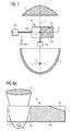
- the figure 1a is a schematic plan view and section along a median plane of a first embodiment of the invention. It is a lighting device for a vehicle headlamp comprising an elliptical reflector 1 and symmetrical in rotation about its optical axis 2.
- the reflector comprises a reflective inner surface 12 whose profile in section along a plane passing through the axis 2 is an ellipse section. Its inner surface 12 corresponds to the section of ellipse visible at the figure 1a describing a rotation around the optical axis and symmetry 2 in a half-space. This half-space is limited by a plane containing the axis 2 and being horizontal.
- This reflector 1 has two foci along its axis 2.
- a light source 3 is positioned approximately at the location of the first focus and the second focus is referenced by the reference sign 4.
- the reflective inner surface 12 of the reflector may not be perfectly elliptical and have one or more specific or complex profiles in order to optimize the light distribution in the lighting beam. This may imply that the reflector 1 is not perfectly symmetrical in revolution.
- the light source 3 is of the light-emitting diode type or LED which emits the majority of its light energy towards the reflective inner surface 12 of the reflector 1.
- This type of light source has the particularity of being particularly compact to the point where it can be assimilated in an approximate manner to a point source.
- Other known types of light source can, however, also be considered.
- the majority of the light rays emitted by the light source 3 are reflected by the reflective surface 12 of the reflector 1.
- the rays Reflected by the reflector all converge towards the second focus 4.
- the light source is not punctual and the shape of the reflective surface 12 is not necessarily perfectly elliptical so that the reflected rays do not all converge towards the second focus 4 but rather to an area close to the second focus 4.
- a movable optical element 6 is disposed near the second focus 4 in the horizontal plane containing the optical axis and symmetry 2 of the reflector 1.
- This optical element 6 is better illustrated at the figure 1b which is a schematic view in elevation of the device of the figure 1a .
- the section is in the horizontal plane including the axis 2.
- the optical element 6 is movable in translation along its longitudinal axis 11 perpendicular to the optical axis 2 and included in the horizontal plane.
- the optical element comprises a substantially planar surface which itself comprises different optically different areas to provide different functions of the illumination device.
- the optical element 6 is actuated in translation along the axis X by an actuator 10 and in translation along the axis Z by an actuator 14.
- actuators can be of the electric type such as for example an electric motor, a piezoelectric motor , or any other type of actuator known to those skilled in the art and adapted to move the optical element 6.
- the different optical zones of the optical element 6 may be of the reflecting type, transparent, transparent colored , scattering, lens, or a spatial combination of these different types, etc ...
- the optical element 6 is displaceable in a substantially horizontal plane, according to combined movements perpendicular (s) to the optical axis 2 and parallel (s) to the optical axis 2, by means of a single piezoelectric motor, with appropriate control of the activation frequencies.
- the light rays 7 reflected by the reflector 1 which converge towards the second focus 4 and which meet the surface of the optical element 6 are reflected or transmitted depending on the optical nature of the surface portion encountered. If the surface encountered is reflective, the spokes 7 will be reflected upwards with respect to the axis 2 as shown in FIG. figure 1a .
- the rays 9 reflected by the reflector not meeting the surface of the optical element 6 propagate downwards with respect to the axis 2, as is also illustrated in FIG. figure 1a .
- a lens 5 is provided on the optical path of the device.
- This lens of the convex plane type has its focus corresponding to the second focus 4 of the reflector 1 and its optical axis coincides with the optical axis of the reflector so that the light rays coming from the focus 4 are transmitted substantially parallel to the optical axis 2.
- Other types of convergent lens are conceivable, such as a biconvex lens or convergent meniscus type.
- a reflector of the paraboloid mirror type is also conceivable. In this case, its optical axis would be substantially perpendicular or at least transverse to the axis 2 and its focus would be approximately coincident with the focus 4. Such a reflector would then reflect the light rays in a direction substantially parallel to its optical axis, that is to say substantially transversely or perpendicularly to the optical axis 2.
- FIG. 1a and 1b the light rays coming from the reflector are inverted with respect to a vertical plane and also with respect to a horizontal plane after their passage towards the focus 4 and the optical element 6.
- An XYZ reference is represented at Figures 1a and 1b where the axis Z corresponds to the optical axis 2 and approximately to the axis of projection, the axis X corresponds to the perpendicular to the axis Z and contained in the plane delimiting the half-space of the reflector 1 and comprising the 11 axis of displacement of the optical element 6, and the Y axis corresponds to the perpendicular to the plane defined by the axes X and Z.
- the rays reflected by the reflector 1 intersect the optical axis 2 at the optical element 6 and pass on the other side of the vertical plane or the plane containing the axis 2 and parallel to the Y axis. same phenomenon occurs with respect to the plane containing the axis 2 and parallel to the X axis.
- figure 1a shows in fact that the rays reflected by the reflector 1 intersect the plane in question and, for those not reflected by the optical element 6, pass on the other side of the plane. This phenomenon does not apply to the rays 7 reflected at the plane by the optical element, which remain on the same side of the plane.
- the optical element 6 may comprise four or more distinct optical zones. These are illustrated in detail in Figures 2 to 6 .
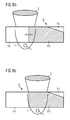
- the first zone 6a is of the concave plane lens type in order to diffuse the light rays.
- the principle of this phenomenon is illustrated in figure 3 .
- the element 6 When the element 6 is positioned to present the area 6a to light rays from the reflector 1, they pass through the area 6a and are diffracted in a divergent manner so as to illuminate a large part of the lens. This generates an enlarged illumination beam which, combined with a reduction in the power of the light source, corresponds to the daylighting function commonly known as DRL (Daytime Running Light).
- DRL Daytime Running Light
- the divergence function of the zone 6a can be reached by various known means, for example and non-exhaustively a diffusing surface treatment or a divergent microlens array.
- the second zone 6b of the optical element 6 is a so-called "folding" reflecting surface.
- the optical principle of operation of this zone is illustrated in figure 4 the light rays coming from the reflector 1 meeting this surface are reflected at an angle to the vertical at the surface which is equal to that of the incident rays. These incident rays are sent back to the upper part of the lens.
- the rays not meeting the reflective surface 6b traverse the horizontal plane and evolve in the lower half-space without deflection to the lens.
- the boundary between the reflective zone 6b and the region of the horizontal plane traversed by the non-deflectable rays is physically formed by the leading edge and / or possibly rearward of the zone 6b and is called the cutting edge.
- the rays 8 reflected by the folder are refracted by the upper part of the lens. These rays reflected by the folder will therefore generate rays projected by the lens whose imprint will be different from that which would be generated by these rays if they were not reflected by the folder.
- the reflected rays are projected by the upper part of the lens slightly inclined downwardly with respect to the optical axis whereas these rays would have been projected by the lower part of the lens slightly inclined upwards with respect to the optical axis if they had been transmitted without reflection.
- This effect can also be reinforced or influenced by various parameters such as, for example, a slight inclination of the folder with respect to the optical axis, a complex non-planar shape of the folder, a complex shape of the lens (or of a paraboloidal reflector). in place of the lens) and / or a slight offset of the folder along the Y axis relative to to the optical axis.
- the optical element 6 can be displaced along the axis Z corresponding to the optical axis by means of an actuator 14. These displacements make it possible to move the cutting edge forward or backward so as to modulate the height cut-off of the beam projected by the device. This function is particularly suitable for compensating for changes in inclination of the device such as the attitude of the vehicle on which the device is mounted.
- This adaptation may be punctual when starting the vehicle to compensate, for example, a large load of the trunk or may be permanent when driving the vehicle to compensate, for example, a change of attitude in a longitudinal plane when braking or accelerations.
- the cutting edge does not have to be straight and perpendicular to the optical axis, it can indeed be inclined or have a complex profile in order to optimize the projected impression and / or to compensate for certain aberrations inherent to certain elements. optics.
- the reflective optical zone 6b may correspond to a so-called "code” or "low beam” function for crossing with other vehicles coming in the opposite direction, where the impression of the projected beam is cut in its upper part.
- An inclination of the cutting edge (not shown) makes it possible to obtain an imprint whose upper part varies along the X axis.
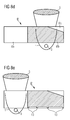
- the third zone 6c of the optical element 6 is a partially transparent and partially reflecting surface. It has an L shape, where the L branches are transparent and the rest of the area is reflective. The reflective part is represented by the hatched area.
- This zone corresponds to a so-called “selective" function that makes it possible to vary the projected impression along the X axis so as to match the cut portion to a vehicle coming in the opposite direction.
- the reflecting surface will reflect light rays from the reflector (1) which will then be refracted by the lens (5).
- the reflective surface of the zone 6c will therefore limit the height of the beam on its left.
- Area 6c shown in figure 2 corresponds to a vehicle headlight.
- the projector on the opposite side shall have a zone 6c symmetrical about the Z axis.
- Each headlamp will therefore have in this function a lighting beam with a darkened area at the top of the other projector's side, respectively, thus forming a high window darkened in the lighting footprint of both projectors.
- the two respective zones 6c can then be moved in a continuous and controlled manner according to the position of the opposite vehicle so as to move the window transversely along the X axis.
- the movements of the optical elements of the two projectors in the "selective" function need not necessarily be identical. Indeed, it may be desired or necessary to expand the window according to the approximation of the opposite vehicle and thereby move the optical elements of the two projectors in a differentiated manner.
- the entire optical device of the headlight can be rotated along an axis substantially parallel to the axis Y.
- a displacement of the window along the axis Y can also be displaced along the optical axis or Z axis. Such a displacement is desirable or even necessary so that the window can follow an opposing vehicle approaching.
- the shape of the reflective part may be different from that of the figure 2 .
- the optical principle of operation is illustrated in figure 5 showing that some rays cross the surface without (or with very little) deviation and others are reflected according to the location of the area they encounter.
- the fourth zone 6d of the optical element is a transparent surface or empty of any optical function.
- the optical principle of operation is illustrated in figure 6 which illustrates that all rays are transmitted without (or with very little) deviation. This position corresponds to a function called "road” or "High Beam", that is to say, a natural imprint uncut optical device.
- the device described thus makes it possible to provide four lighting functions by means of a single light source.
- the passage from one function to another is done by means of the actuator 10 which displaces the optical element 6 in translation until the corresponding zone is in a position centered longitudinally on the focal point 4 of the optical device.
- a second embodiment is illustrated in Figures 7 and 8a-8d .
- the architecture of this device is similar to that of the first embodiment, namely an elliptical reflector 1 in a half-space, a light source 3 illuminating essentially in the half-reflector space and positioned at the first focus of the reflector, an optical element 6 'movable transversely and longitudinally to the level of the second focus 4 of the reflector and a lens whose focus corresponds to the second focus 4 of the reflector.
- This device is distinguished from that of the first embodiment by the optical element 6 '. It comprises two optical zones: a first zone 6a 'transparent and a second zone comprising a major portion 6b' reflecting and a minor transparent portion 6c '.
- the border between the reflective portion 6b 'and the transparent portion 6c' corresponds to the cutoff edge.
- the device has four functions that are schematically illustrated in FIGS. Figures 8a to 8d .
- the optical element 6 ' is enlarged therein for the sake of clarity.
- the first function is illustrated in figure 8a where the transparent area is in function, that is, positioned transversely at the second focus of the reflector.
- This first function is the so-called “road” or “high beam” function generating a natural projection footprint of the optical device.
- the second function is illustrated in figure 8b where the zones 6a 'and 6b' are straddling the region of the second focus where the rays coming from the reflector 1 pass.
- This function is said to be “selective” which makes it possible to vary along the X axis the projected imprint so as to Match the cut portion to a vehicle coming in the opposite direction.
- the transverse position of the optical element is continuously variable in order to be able to "follow" the position of the oncoming vehicle. Practically speaking, a portion of the rays reflected by the reflector are reflected by the reflecting surface 6b '. The reflection caused by the so-called "folding" reflective surface will reduce the height of the corresponding part of the impression. The height of the impression is thus reduced to its left.
- the progressive displacement of the optical element 6 'to the left corresponding to an increase of the active reflecting surface will modify the impression of the projected beam by widening the lowering of height to the right.
- This function in combination with a second symmetrical headlamp makes it possible to form a darkened window by adapting the cutting and lowering of the beam to an opposite vehicle whose angular position relative to the vehicle illuminated by the device varies.
- a displacement of the window along the Y axis can also be combined with a displacement along the optical axis or axis Z. Such a displacement is desirable or necessary so that the window can follow an opposite vehicle approaching.
- the third function is illustrated in figure 8c where the reflective rectangular portion of the zone 6b 'is active. It generates a cut across the entire width of the footprint. It may be a so-called “tourist” function that is that of a vehicle normally rolling on the left and rolling in a territory where one is driving on the right. The projected beam is cut across its entire width and thus avoids a glare that would otherwise take place in lighting of the type "code” or "crossing" for a roller on the left.
- the fourth function is illustrated in figure 8d where the transparent area 6c 'is partially active. In this position, a part of the rays coming from the right part of the reflector 1 meets and crosses the transparent part 6c 'and is then refracted and projected towards the upper left part of the beam. Corresponding rays from the left reflector portion are reflected by the reflecting surface 6b '. Part of the rays can pass the front edge of the reflective surface. The resulting imprint is limited in height due to the cutting edge before the reflective surface, and in an inverted manner. The section of the cutting edge which is more advanced than the inclined edge limits the height on the right side of the impression and the inclined edge limits the height on the left side of the impression to a lesser extent and in a progressive manner. This is a "code” or "Low Beam” function for a vehicle intended for driving on the left.
- the optical element should simply have a transparent surface and a reflective portion.
- the reflective part can be made quite simply by metallization on a support.
- the displacement of the optical element must be transversal but not necessarily in translation. Indeed, depending on various parameters such as the available space and the number of functions to be provided, one could provide an optical element slightly curved in the plane of its surface and rotate it according to a center of rotation located for example behind the reflector and the light source on the optical axis.
- the surface of the optical element which comprises the different optical zones does not necessarily have to be flat. On the contrary, depending on the different optical effects desired, one can imagine a slightly complex surface.
- the transverse movement of the optical element need not be perpendicular to the optical axis and in the plane delimiting the half-space of the reflector.
- a transversal movement but not perpendicular as well as in a plane forming a certain angle with the plane delimiting the half-space of the reflector, and this according to various parameters such as, for example, the maximum size.
- the optical element may also be located at a short distance from the plane delimiting the half-space of the reflector, as a function, for example, of the various imperfections and / or aberrations of the optical elements.
- the described embodiments comprise a single light source. It is quite possible to envisage several light sources or several devices similar in parallel where the mobile optical elements would be mechanically linked and move by a single actuator.
Abstract
Description
L'invention a trait à un dispositif d'éclairage pour projecteur, plus particulièrement à un dispositif d'éclairage pour projecteur de véhicule, le dispositif étant apte à assurer plusieurs fonctions d'éclairage et/ou une fonction d'éclairage variable avec une seule source d'éclairage.The invention relates to a projector lighting device, more particularly to a vehicle headlamp lighting device, the device being capable of providing a plurality of lighting functions and / or a variable lighting function with a single lighting device. lighting source.
L'invention concerne plus particulièrement les projecteurs de véhicule équipés d'une ou plusieurs sources lumineuses ponctuelles du type à diodes électroluminescentes ou encore LED. Ce type de source lumineuse est en effet plus performant du point de vue consommation en comparaison avec les sources lumineuses plus classiques comme les lampes halogène ou xénon. La puissance électrique d'une source lumineuse du type LED adaptée à un projecteur de véhicule varie aujourd'hui entre 20 et 30 W alors que celle d'une source halogène de puissance d'éclairage comparable est de l'ordre de 120 W. Il est même raisonnable de penser que des modules LED de même puissance d'éclairage seront bientôt disponibles avec une puissance électrique de l'ordre de 5 à 10W De plus une nouvelle législation européenne prévoit une obligation pour les nouveaux véhicules d'être équipés de projecteurs du type DRL, ou encore « Daytime Running Light », c'est-à-dire des projecteurs destinés à fonctionner en permanence durant le jour. L'impact de l'éclairage sur la consommation de carburant va donc être croissant alors qu'un projet de directive européenne prévoit la taxation dés 2012 des constructeurs de véhicule par gramme de CO2 émis dans l'atmosphère au-delà de 120 gr/km. Étant donné qu'une consommation électrique d'un projecteur halogène de l'ordre de 120 W correspond à environ 0.15 litre de carburant pour 100 km, soit de l'ordre de 5 à 6 gr de CO2/km, l'utilisation de sources lumineuses du type à diodes électroluminescentes pour les projecteurs de véhicule sera d'un intérêt grandissant à l'avenir.The invention relates more particularly to vehicle headlamps equipped with one or more point light sources of the light-emitting diode or LED type. This type of light source is indeed more efficient from the point of view of consumption in comparison with more conventional light sources such as halogen or xenon lamps. The electrical power of a light source of the LED type adapted to a vehicle headlamp now varies between 20 and 30 W while that of a halogen source of comparable lighting power is of the order of 120 W. is even reasonable to think that LED modules with the same lighting power will soon be available with an electric power of the order of 5 to 10W In addition a new European legislation provides an obligation for new vehicles to be equipped with projectors. type DRL, or "Daytime Running Light", that is to say projectors intended to operate continuously during the day. The impact of lighting on fuel consumption will therefore increase as a draft European directive provides for the taxation of vehicle manufacturers as of 2012 per gram of CO 2 emitted into the atmosphere above 120 gr / km. Given that a power consumption of a 120 W halogen floodlight corresponds to approximately 0.15 liter of fuel per 100 km, ie of the order of 5 to 6 gr of CO 2 / km, the use of light-emitting diode-type light sources for vehicle projectors will be of increasing interest in the future.
Le coût des sources d'éclairages à LED reste cependant assez élevé en comparaison avec les sources classiques. La nécessité d'avoir plusieurs fonctions par projecteur, à savoir typiquement les fonctions « route » ou « High Beam » (HB), « code » ou « Low Beam » (LB) et « Daytime Running Light » (DRL) et donc plusieurs sources lumineuses renforce la problématique du coût de l'utilisation de sources à LED.The cost of LED lighting sources, however, remains quite high in comparison with conventional sources. The need to have several functions per projector, namely typically the functions "road" or "High Beam" (HB), "code" or "Low Beam" (LB) and "Daytime Running Light" (DRL) and therefore several light sources reinforces the issue of the cost of using LED sources.
De plus l'utilisation de sources d'éclairages à LED implique pour chaque source un module électronique de gestion. Le boîtier du projecteur s'en verra par conséquent plus compliqué, plus volumineux et plus coûteux.In addition, the use of LED lighting sources implies for each source an electronic management module. The projector case will therefore be more complicated, bulkier and more expensive.
Le document
Le document
Le document
Les enseignements de ces documents n'agissent qu'au niveau de la coupure nécessaire pour la fonction « code ». Ils prévoient essentiellement de déplacer le bord de coupure afin de rendre la coupure active ou non et d'assurer ainsi le passage de la fonction « route » à la fonction « code » et vice versa. Ils ne permettent par exemple pas d'assurer d'autres fonctions qui seront bientôt nécessaires ou souhaitables comme la fonction DRL ou encore une fonction de variation de l'empreinte du faisceau en fonction de paramètres extérieurs comme la présence d'une voiture venant en face, et ce au moyen de la même source lumineuse.The teachings of these documents act only at the level of the cut required for the "code" function. They mainly plan to move the cutoff edge to make the cut active or not and thus ensure the passage of the function "route" to the function "code" and vice versa. They do not allow, for example, other functions that will soon be necessary or desirable, such as the DRL function, or a function for varying the beam footprint depending on external parameters, such as the presence of a car in front of it. by the same light source.
Les documents
L'objectif de l'invention est de proposer un dispositif d'éclairage permettant d'assurer plusieurs fonctions avec une seule source de lumière ou un nombre de sources de lumière limité, et ce avec d'avantage de possibilités que dans l'état de l'art.The object of the invention is to propose a lighting device that makes it possible to perform several functions with a single light source or a limited number of light sources, and with more possibilities than in the state of light. art.
L'invention consiste en un dispositif d'éclairage pour projecteur, notamment de véhicule, comprenant: un réflecteur comportant un premier foyer, un second foyer et un axe optique passant par le premier et le second foyer ; une source lumineuse située à proximité du premier foyer du réflecteur de sorte que les rayons lumineux émis par la source lumineuse soient réfléchis par le réflecteur approximativement vers son second foyer ; un premier élément optique comportant un foyer et un axe optique, le foyer étant situé à proximité du second foyer du réflecteur, le premier élément optique étant apte à projeter les rayons lumineux émis par la source et réfléchis par le réflecteur en un faisceau selon son axe optique ; un second élément optique de préférence comprenant une surface généralement plane dont une zone est située à proximité du second foyer du réflecteur de sorte à recevoir avec un angle d'incidence les rayons lumineux émis par la source et réfléchis par le réflecteur ; où le second élément optique, de préférence généralement horizontal, est mobile dans le plan de sa surface, notamment sensiblement transversalement à l'axe optique du réflecteur, de sorte à pouvoir déplacer ladite zone hors des rayons lumineux.The invention consists of a projector lighting device, especially a vehicle, comprising: a reflector having a first focus, a second focus and an optical axis passing through the first and second focus; a light source located near the first focus of the reflector so that the light rays emitted by the light source are reflected by the reflector approximately to its second focus; a first optical element having a focal point and an optical axis, the focus being located near the second focus of the reflector, the first optical element being adapted to project the light rays emitted by the source and reflected by the reflector in a beam along its optical axis; a second optical element preferably comprising a generally planar surface, a zone of which is located near the second focus of the reflector so as to receive, with an angle of incidence, the light rays emitted by the source and reflected by the reflector; wherein the second optical element, preferably generally horizontal, is movable in the plane of its surface, in particular substantially transversely to the optical axis of the reflector, so as to be able to move said zone out of the light rays.
Ce dispositif présente l'avantage de permettre d'assurer des fonctions d'éclairage différentes d'un simple déplacement du bord de coupure, et ce avec une seule source lumineuse ou un nombre de sources lumineuses constant en cas de montage en parallèle de plusieurs dispositifs. De par l'agencement transversal proposé, le nombre de fonctions peut être assez élevé.This device has the advantage of making it possible to provide lighting functions that are different from a simple displacement of the cutoff edge, and this with a single light source or a constant number of light sources in the case of parallel mounting of several devices. . By the proposed transversal arrangement, the number of functions can be quite high.
Selon une caractéristique avantageuse, la surface du second élément optique comprend au moins deux zones positionnées l'une à côté de l'autre transversalement à l'axe optique du réflecteur, chaque zone étant au moins d'un des types suivants : réfléchissante, transparente, colorée, diffusante ou lentille divergente ou une combinaison spatiale de ces différents types.According to an advantageous characteristic, the surface of the second optical element comprises at least two zones positioned one beside the other transversely to the optical axis of the reflector, each zone being at least one of the following types: reflective, transparent , colored, scattering or divergent lens or a spatial combination of these different types.
Selon une caractéristique avantageuse de l'invention, le second élément mobile est mobile dans un plan sensiblement horizontal, de préférence selon des directions combinées perpendiculaire(s) à l'axe optique et parallèle(s) à l'axe optique.According to an advantageous characteristic of the invention, the second mobile element is movable in a substantially horizontal plane, preferably in combined directions perpendicular to the optical axis and parallel to the optical axis.
Selon une caractéristique avantageuse, la surface du second élément optique est de forme allongée, préférentiellement essentiellement rectangulaire, avec un axe longitudinal, comportant au moins deux zones réparties le long de l'axe longitudinal, dont les caractéristiques optiques sont différentes et sélectionnées parmi les suivantes : réfléchissante, transparente, colorée, diffusante ou lentille divergente ou une combinaison spatiale de ces différents typesAccording to an advantageous characteristic, the surface of the second optical element is of elongate shape, preferably substantially rectangular, with a longitudinal axis, comprising at least two zones distributed along the longitudinal axis, whose optical characteristics are different and selected from the following ones: : reflective, transparent, colored, diffusing or divergent lens or a spatial combination of these different types
Selon une caractéristique avantageuse, le second élément optique est mobile en translation, préférentiellement généralement selon une direction perpendiculaire à l'axe optique du réflecteur.According to an advantageous characteristic, the second optical element is movable in translation, preferably generally in a direction perpendicular to the optical axis of the reflector.
Selon une caractéristique avantageuse, la surface du second élément optique est de forme allongée légèrement courbée selon un courbe principale, préférentiellement selon un arc de cercle, et comportant au moins deux zones réparties le long de sa courbe principale, dont les caractéristiques optiques sont différentes et sélectionnées parmi les suivantes : réfléchissante, transparente, colorée, diffusante ou lentille divergente ou une combinaison spatiale de ces différents typesAccording to an advantageous characteristic, the surface of the second optical element is of elongated shape slightly curved along a main curve, preferably in a circular arc, and comprising at least two zones distributed along its main curve, the optical characteristics of which are different and selected from among the following: reflective, transparent, colored, diffusing or divergent lens or a spatial combination of these different types
Selon une caractéristique avantageuse, le second élément optique est mobile en rotation selon un rayon suffisamment grand que pour assurer un mouvement des zones qui soit transversal à l'axe optique du réflecteur.According to an advantageous characteristic, the second optical element is rotatable along a sufficiently large radius as to ensure a movement of the zones which is transverse to the optical axis of the reflector.
Selon une caractéristique avantageuse, la surface du second élément optique comprend une zone réfléchissante avec un bord dit bord de coupure croisant l'axe optique du réflecteur, préférentiellement du côté opposé au réflecteur.According to an advantageous characteristic, the surface of the second optical element comprises a reflective zone with a so-called edge cutting edge crossing the optical axis of the reflector, preferably on the opposite side to the reflector.
Selon une caractéristique avantageuse, le bord de coupure présente un profil variable selon une direction généralement perpendiculaire à l'axe optique du premier réflecteur.According to an advantageous characteristic, the cutting edge has a variable profile in a direction generally perpendicular to the optical axis of the first reflector.
Selon une caractéristique avantageuse, le bord de coupure présente un profil constant selon une direction généralement perpendiculaire à l'axe optique du premier réflecteur.According to an advantageous characteristic, the cutting edge has a constant profile in a direction generally perpendicular to the optical axis of the first reflector.
Selon une caractéristique avantageuse, le réflecteur comporte une surface réfléchissante courbe, préférentiellement elliptique, dans un demi-espace limité par un plan, le premier et le second foyer du réflecteur étant situés approximativement dans ledit plan, le second élément optique étant mobile dans ledit plan ou parallèlement audit plan.According to an advantageous characteristic, the reflector comprises a curved reflecting surface, preferably elliptical, in a half-space limited by a plane, the first and second focus of the reflector being situated approximately in said plane, the second optical element being movable in said plane or parallel to said plan.
Selon une caractéristique avantageuse, le second élément optique est mobile avec au moins deux positions indexées.According to an advantageous characteristic, the second optical element is mobile with at least two indexed positions.
Selon une caractéristique avantageuse, le second élément optique est mobile de manière continue, préférentiellement entre deux positions indexées.According to an advantageous characteristic, the second optical element is continuously movable, preferably between two indexed positions.
Selon une caractéristique avantageuse, la surface du second élément optique comporte au moins deux repères optiques correspondant aux positions indexées, les repères optiques étant préférentiellement réalisés par métallisation.According to an advantageous characteristic, the surface of the second optical element comprises at least two optical markers corresponding to the indexed positions, the optical markers being preferentially made by metallization.
Selon une caractéristique avantageuse, le second élément optique est mobile en translation et/ou en rotation au moyen d'un moteur électrique par exemple un moteur pas à pas, un moteur piézoélectrique ou un solénoïde, notamment soit avec deux actuateurs spécifiques de type moteur pas à pas ou piézoélectrique ou solénoïde, soit avec la combinaison de deux de ces types d'actuateurs, soit avec un seul moteur piézoélectrique en pilotant la fréquence d'activation de façon appropriée.According to an advantageous characteristic, the second optical element is movable in translation and / or in rotation by means of an electric motor, for example a stepping motor, a piezoelectric motor or a solenoid, in particular with two specific actuators of the motor type. step or piezoelectric or solenoid, either with the combination of two of these types of actuators, or with a single piezoelectric motor by controlling the activation frequency appropriately.
Selon une caractéristique avantageuse, le premier élément optique est du type réflecteur dont l'axe optique croise l'axe optique du réflecteur, préférentiellement dont l'axe optique est perpendiculaire à l'axe optique du réflecteur.According to an advantageous characteristic, the first optical element is of the reflector type, the optical axis of which crosses the optical axis of the reflector, preferably whose optical axis is perpendicular to the optical axis of the reflector.
Selon une caractéristique avantageuse, le premier élément optique est une lentille dont l'axe optique correspond essentiellement à l'axe optique du réflecteur.According to an advantageous characteristic, the first optical element is a lens whose optical axis corresponds essentially to the optical axis of the reflector.
Selon une caractéristique avantageuse, le second élément optique est mobile également essentiellement selon l'axe optique du réflecteur, préférentiellement en translation, au moyen d'un actuateur.According to an advantageous characteristic, the second optical element is also essentially movable along the optical axis of the reflector, preferably in translation, by means of an actuator.
Selon une caractéristique avantageuse, le dispositif comprend un dispositif de commande de l'actuateur du second élément optique selon l'axe optique, apte à déplacer, préférentiellement de manière dynamique, une surface réfléchissante du second élément optique afin de compenser les changements d'assiette du véhicule.According to an advantageous characteristic, the device comprises a device for controlling the actuator of the second optical element along the optical axis, capable of displacing, preferably dynamically, a reflecting surface of the second optical element in order to compensate for changes in attitude. of the vehicle.
La plieuse selon l'invention est de préférence sensiblement plane et horizontale, comportant éventuellement des zones transparentes.The folder according to the invention is preferably substantially flat and horizontal, possibly comprising transparent areas.
Cette plieuse est avantageusement mobile horizontalement.This folder is advantageously movable horizontally.
La plieuse peut, si on le souhaite, être capable d'être déplacée suivant une rotation autour d'un axe vertical éloigné.The folder may, if desired, be able to be rotated about a distant vertical axis.
L'invention concerne également un projecteur ou un feu arrière de véhicule comprenant un dispositif tel que définit ci-avant.The invention also relates to a vehicle headlight or taillight comprising a device as defined above.
L'invention concerne également un véhicule équipé d'un tel projecteur ou d'un tel feu arrière.The invention also relates to a vehicle equipped with such a projector or such a rear light.
D'autre caractéristiques et avantages de l'invention apparaîtront dans la description détaillée suivante des modes de réalisation de l'invention, donnée à titre indicatif et nullement limitatif.Other features and advantages of the invention will appear in the following detailed description of the embodiments of the invention, given for information only and in no way limiting.
Dans les figures suivantes :
- La
figure 1a est une vue schématique en plan et en coupe d'un premier exemple de dispositif d'éclairage pour projecteur de véhicule selon l'invention. - La
figure 1b est une vue schématique en élévation et en coupe du premier exemple de dispositif d'éclairage selon lafigure 1a . - La
figure 2 est une vue schématique en élévation de l'élément optique mobile du dispositif desfigures 1a et 1 b. - La
figure 3 est une vue schématique du principe de fonctionnement optique de lazone 6a de l'élément optique de lafigure 2 . - La
figure 4 est une vue schématique du principe de fonctionnement optique de lazone 6b de l'élément optique de lafigure 2 . - La
figure 5 est une vue schématique du principe de fonctionnement optique de lazone 6c de l'élément optique de lafigure 2 . - La
figure 6 est une vue schématique du principe de fonctionnement optique de lazone 6d de l'élément optique de lafigure 2 . - La
figure 7 est une vue schématique en élévation et en coupe d'un second exemple de dispositif d'éclairage pour projecteur de véhicule selon l'invention. - La
figure 8a est une vue schématique en élévation illustrant le principe de fonctionnement du dispositif de lafigure 7 en position dite « route ». - La
figure 8b est une vue schématique en élévation illustrant le principe de fonctionnement du dispositif de lafigure 7 en position dite « sélective ». - La
figure 8c est une vue schématique en élévation illustrant le principe de fonctionnement du dispositif de lafigure 7 en position dite « touriste ». - La
figure 8d est une vue schématique en élévation illustrant le principe de fonctionnement du dispositif de lafigure 7 en position dite « code ». - La
figure 8e est une vue schématique en élévation du dispositif de lafigure 7 illustrant les repères optiques de positionnement de l'élément optique mobile.
- The
figure 1a is a schematic plan view in section of a first example of a vehicle headlamp lighting device according to the invention. - The
figure 1b is a schematic view in elevation and in section of the first example of a lighting device according to thefigure 1a . - The
figure 2 is a schematic view in elevation of the mobile optical element of the device ofFigures 1a and 1 b. - The
figure 3 is a schematic view of the principle of optical operation of thezone 6a of the optical element of thefigure 2 . - The
figure 4 is a schematic view of the principle of optical operation of thezone 6b of the optical element of thefigure 2 . - The
figure 5 is a schematic view of the principle of optical operation of thezone 6c of the optical element of thefigure 2 . - The
figure 6 is a schematic view of the principle of optical operation of thezone 6d of the optical element of thefigure 2 . - The
figure 7 is a schematic view in elevation and in section of a second example of a vehicle headlighting device according to the invention. - The
figure 8a is a schematic view in elevation illustrating the principle of operation of the device of thefigure 7 in position called "road". - The
figure 8b is a schematic view in elevation illustrating the principle of operation of the device of thefigure 7 in so-called "selective" position. - The
figure 8c is a schematic view in elevation illustrating the principle of operation of the device of thefigure 7 in so-called "tourist" position. - The
figure 8d is a schematic view in elevation illustrating the principle of operation of the device of thefigure 7 in the so-called "code" position. - The
figure 8e is a schematic view in elevation of the device of thefigure 7 illustrating the optical positioning marks of the mobile optical element.
Les modes de réalisation de l'invention sont illustrés dans les figures et décrits ci-après par rapport à une position de montage du dispositif dans un véhicule en qualité de projecteur. Ce type d'application bien que prépondérant n'est pas limitatif si bien que les termes employés tels que « horizontal », « vertical », « haut », « bas », « supérieur(e) », « inférieur(e) » par exemple, en vue de décrire les positions des différents éléments ne sont pas absolus mais plutôt à interpréter de manière relative décrivant les positions des éléments par rapport à leur disposition sur les figures. Les dispositifs d'éclairage décrits pourraient être montés dans d'autres positions et/ou pour d'autres applications. De plus, les positions relatives des différents éléments optiques tels que les sources lumineuses, les réflecteurs et les lentilles exprimées pour la simplicité de compréhension par alignement des axes optiques et/ou correspondance des foyers respectifs ne sont pas à interpréter de manière exacte dans la mesure où de légères variations sont envisageables voire souhaitables en vue, entre autres, de corriger le caractère non parfait et certaines aberrations optiques des éléments optiques ou d'obtenir certains effets supplémentaires.Embodiments of the invention are illustrated in the figures and described hereinafter with respect to a mounting position of the device in a vehicle as a projector. This type of application although preponderant is not limiting so that the terms used such as "horizontal", "vertical", "high", "low", "superior", "lower" for example, in order to describe the positions of the different elements are not absolute but rather to interpret in a relative manner describing the positions of the elements with respect to their arrangement in the figures. The described lighting devices could be mounted in other positions and / or for other applications. In addition, the relative positions of the various optical elements such as light sources, reflectors and lenses expressed for simplicity of understanding by alignment of the optical axes and / or correspondence of the respective foci are not to be interpreted accurately in the measurement where slight variations are conceivable or even desirable in order, among other things, to correct the non-perfect nature and certain optical aberrations of the optical elements or to obtain certain additional effects.
La
Il est à noter que la surface interne réfléchissante 12 du réflecteur peut ne pas être parfaitement elliptique et avoir un ou plusieurs profils spécifiques ou complexes en vue d'optimiser la répartition lumineuse dans le faisceau d'éclairage. Ceci peut impliquer que le réflecteur 1 ne soit pas parfaitement symétrique en révolution.It should be noted that the reflective
La source de lumière 3 est du type à diode électroluminescente ou encore LED qui émet la majorité de son énergie lumineuse vers la surface interne réfléchissante 12 du réflecteur 1. Ce type de source lumineuse à la particularité d'être particulièrement compact au point de pouvoir être assimilée d'une manière approximative à une source ponctuelle. D'autres types de source lumineuse connus peuvent cependant également être considérés.The
La majorité des rayons lumineux émis par la source lumineuse 3 sont réfléchis par la surface réfléchissante 12 du réflecteur 1. En assimilant la source lumineuse à une source ponctuelle localisée au premier foyer du réflecteur et en assimilant le réflecteur à un réflecteur elliptique parfait, les rayons réfléchis par le réflecteur convergent tous vers le second foyer 4. Dans la réalité, la source lumineuse n'est pas ponctuelle et la forme de la surface réfléchissante 12 n'est pas nécessairement parfaitement elliptique si bien que les rayons réfléchis ne convergent pas tous vers le second foyer 4 mais plutôt vers une zone proche du second foyer 4.The majority of the light rays emitted by the
Un élément optique mobile 6 est disposé à proximité du second foyer 4 dans le plan horizontal contenant l'axe optique et de symétrie 2 du réflecteur 1. Cet élément optique 6 est mieux illustré à la
Avantageusement, l'élément optique 6 est déplaçable suivant un plan sensiblement horizontal, selon des mouvements combinés perpendiculaire(s) à l'axe optique 2 et parallèle(s) à l'axe optique 2, au moyen d'un seul moteur piézoélectrique, avec un pilotage approprié des fréquences d'activation.Advantageously, the
Des moyens de guidage (non représentés) en translation de l'élément optique doivent être prévus de manière connue de l'homme de l'art.Guide means (not shown) in translation of the optical element must be provided in a manner known to those skilled in the art.
Les rayons lumineux 7 réfléchis par le réflecteur 1 qui convergent vers le second foyer 4 et qui rencontrent la surface de l'élément optique 6 sont réfléchis ou transmis en fonction de la nature optique de la partie de surface rencontrée. Si la surface rencontrée est réfléchissante, les rayons 7 seront réfléchis vers le haut par rapport à l'axe 2 comme cela est illustré à la
Une lentille 5 est prévue sur le chemin optique du dispositif. Cette lentille du type plan convexe a son foyer correspondant au second foyer 4 du réflecteur 1 et son axe optique confondu avec l'axe optique du réflecteur de sorte que les rayons lumineux provenant du foyer 4 sont transmis essentiellement parallèlement à l'axe optique 2. D'autres types de lentille convergente sont envisageables, comme par exemple une lentille biconvexe ou encore du type ménisque convergent. Un réflecteur du type miroir paraboloïdal est également envisageable. Dans ce cas, son axe optique serait essentiellement perpendiculaire ou à tout le moins transversal à l'axe 2 et son foyer serait approximativement confondu avec le foyer 4. Un tel réflecteur réfléchirait alors les rayons lumineux dans une direction essentiellement parallèle à son axe optique, c'est-à-dire essentiellement transversalement ou perpendiculairement à l'axe optique 2.A
Comme cela est visible aux
L'élément optique 6 peut comporter quatre zones optiques distinctes ou plus. Celles-ci sont illustrées en détail aux
La première zone 6a est du type lentille plan concave en vue de diffuser les rayons lumineux. Le principe de ce phénomène est illustré à la
La seconde zone 6b de l'élément optique 6 est une surface réfléchissante dite « plieuse ». Le principe optique de fonctionnement de cette zone est illustré à la
La troisième zone 6c de l'élément optique 6 est une surface partiellement transparente et partiellement réfléchissante. Elle présente une forme en L, où les branches du L sont transparentes et le reste de la zone est réfléchissante. La partie réfléchissante est représentée par la zone hachurée. Cette zone correspond à une fonction dite « sélective » qui permet de faire varier l'empreinte projetée selon l'axe X de sorte à faire correspondre la partie coupée à un véhicule venant en sens opposé. La surface réfléchissante va réfléchir les rayons lumineux provenant du réflecteur (1) qui vont ensuite être réfractés par la lentille (5). La surface réfléchissante de la zone 6c va donc limiter la hauteur du faisceau sur sa gauche. La zone 6c représentée à la
La quatrième zone 6d de l'élément optique est une surface transparente ou vide de toute fonction optique. Le principe optique de fonctionnement est illustré à la
Le dispositif décrit permet ainsi d'assurer quatre fonctions d'éclairage au moyen d'une seule source lumineuse. Le passage d'une fonction à une autre se fait au moyen de l'actuateur 10 qui déplace en translation l'élément optique 6 jusqu'à ce que la zone correspondante soit en position centrée longitudinalement sur le foyer 4 du dispositif optique.The device described thus makes it possible to provide four lighting functions by means of a single light source. The passage from one function to another is done by means of the
Un second mode de réalisation est illustré aux
La première fonction est illustrée à la
La seconde fonction est illustrée à la
La troisième fonction est illustrée à la
La quatrième fonction est illustrée à la
Ce dispositif permet de réaliser de manière assez simple un projecteur avec quatre fonctions. L'élément optique doit simplement comporter une surface transparente et une partie réfléchissante. La partie réfléchissante peut être réalisée assez simplement par métallisation sur un support. A cet effet, il peut être intéressant de réaliser des repères optiques de position 13 en même temps que la surface réfléchissante. Ceux-ci sont illustrés à la
Il est à noter que diverses combinaisons de fonctions d'éclairage décrites sont envisageables. De plus d'autres fonctions sont également envisageables comme par exemple un clignotant en prévoyant une zone transparente colorée au niveau de l'élément optique. Dans ce cas, il serait éventuellement nécessaire de réduire la puissance de la source lumineuse. Une fonction « brouillard » est également possible en prévoyant par exemple une zone réfléchissante plus grande, c'est-à-dire avec un bord de coupure plus avancé (vers la lentille) afin de diriger le faisceau projeté d'avantage vers le bas. Il est également à noter que la présence d'une surface réfléchissante n'est pas nécessaire. On pourrait par exemple prévoir un élément optique avec une zone divergente pour une fonction « DRL » et une zone transparente pour une fonction « route » ou « High Beam ».It should be noted that various combinations of lighting functions described are possible. In addition, other functions are also conceivable, such as example a flashing by providing a transparent area colored at the optical element. In this case, it may be necessary to reduce the power of the light source. A "fog" function is also possible by providing, for example, a larger reflective area, ie with a more advanced cutting edge (towards the lens) in order to direct the projected beam further downwards. It should also be noted that the presence of a reflective surface is not necessary. For example, an optical element with a diverging zone for a "DRL" function and a transparent zone for a "road" or "High Beam" function could be provided.
Il est également à noter que le déplacement de l'élément optique doit être transversal mais pas nécessairement en translation. En effet, en fonction de divers paramètres comme par exemple l'encombrement disponible et le nombre de fonctions à assurer, on pourrait prévoir un élément optique légèrement courbé dans le plan de sa surface et le faire tourner selon un centre de rotation situé par exemple derrière le réflecteur et la source lumineuse sur l'axe optique.It should also be noted that the displacement of the optical element must be transversal but not necessarily in translation. Indeed, depending on various parameters such as the available space and the number of functions to be provided, one could provide an optical element slightly curved in the plane of its surface and rotate it according to a center of rotation located for example behind the reflector and the light source on the optical axis.
Il est également à noter que la surface de l'élément optique qui comporte les différentes zones optiques ne doit pas nécessairement être plane. Au contraire, en fonction des différents effets optiques désirés, on peut imaginer une surface légèrement complexe.It should also be noted that the surface of the optical element which comprises the different optical zones does not necessarily have to be flat. On the contrary, depending on the different optical effects desired, one can imagine a slightly complex surface.
Le mouvement transversal de l'élément optique ne doit pas nécessairement être perpendiculaire à l'axe optique et dans le plan délimitant le demi-espace du réflecteur. On pourrait imaginer un mouvement transversal mais non perpendiculaire ainsi que dans un plan formant un certain angle avec le plan délimitant le demi-espace du réflecteur, et ce en fonction de divers paramètres comme, par exemple, l'encombrement maximum. L'élément optique peut également se situer à une faible distance du plan délimitant le demi-espace du réflecteur, en fonction, par exemple, des différentes imperfections et/ou aberrations des éléments optiques.The transverse movement of the optical element need not be perpendicular to the optical axis and in the plane delimiting the half-space of the reflector. One could imagine a transversal movement but not perpendicular as well as in a plane forming a certain angle with the plane delimiting the half-space of the reflector, and this according to various parameters such as, for example, the maximum size. The optical element may also be located at a short distance from the plane delimiting the half-space of the reflector, as a function, for example, of the various imperfections and / or aberrations of the optical elements.
Les modes de réalisation décrits comportent une seule source lumineuse. Il est tout-à-fait envisageable de prévoir plusieurs sources lumineuses ou plusieurs dispositifs similaires en parallèles où les éléments optiques mobile seraient liés mécaniquement et déplacer par un seul actuateur.The described embodiments comprise a single light source. It is quite possible to envisage several light sources or several devices similar in parallel where the mobile optical elements would be mechanically linked and move by a single actuator.
Claims (16)
Applications Claiming Priority (1)
| Application Number | Priority Date | Filing Date | Title |
|---|---|---|---|
| FR0807289A FR2940403B1 (en) | 2008-12-19 | 2008-12-19 | LIGHTING DEVICE FOR A VEHICLE HEADLAMP PROVIDING MULTIPLE LIGHTING FUNCTIONS OR A VARIABLE FUNCTION WITH A SINGLE LIGHT SOURCE |
Publications (2)
| Publication Number | Publication Date |
|---|---|
| EP2199664A1 true EP2199664A1 (en) | 2010-06-23 |
| EP2199664B1 EP2199664B1 (en) | 2015-09-23 |
Family
ID=40763469
Family Applications (1)
| Application Number | Title | Priority Date | Filing Date |
|---|---|---|---|
| EP09178159.1A Active EP2199664B1 (en) | 2008-12-19 | 2009-12-07 | Lighting device for vehicle projector, allowing a pluratity of lighting functions or a variable function with only one light source |
Country Status (3)
| Country | Link |
|---|---|
| EP (1) | EP2199664B1 (en) |
| JP (1) | JP5629457B2 (en) |
| FR (1) | FR2940403B1 (en) |
Cited By (11)
| Publication number | Priority date | Publication date | Assignee | Title |
|---|---|---|---|---|
| WO2012034936A1 (en) * | 2010-09-18 | 2012-03-22 | Automotive Lighting Reutlingen Gmbh | Motor vehicle headlight comprising a multifunctional projection module |
| EP2546569A2 (en) | 2011-07-13 | 2013-01-16 | Valeo Vision | Multifunctional lighting/signalling device for a motor vehicle |
| DE102012224345A1 (en) * | 2012-12-21 | 2014-06-26 | Osram Gmbh | Vehicle lighting device |
| EP2228593A3 (en) * | 2009-03-12 | 2015-03-11 | Koito Manufacturing Co., Ltd. | Vehicle headlamp |
| WO2015185339A1 (en) * | 2014-06-03 | 2015-12-10 | Osram Gmbh | Illumination device |
| FR3022322A1 (en) * | 2014-06-16 | 2015-12-18 | Valeo Vision | ROTARY LIGHTING AND / OR SIGNALING MODULE |
| CN107013862A (en) * | 2015-12-10 | 2017-08-04 | 法雷奥照明公司 | Motor vehicles lighting module with combination dipped beam and road function and tunable light source |
| EP3428012A3 (en) * | 2017-06-22 | 2019-03-06 | LG Electronics Inc. | Lamp for vehicle |
| WO2021170400A1 (en) * | 2020-02-27 | 2021-09-02 | Valeo Vision | Motor vehicle light module comprising an electrochromic device |
| FR3107749A1 (en) * | 2020-02-27 | 2021-09-03 | Valeo Vision | Motor vehicle light module comprising an electrochromic device |
| CN114423992A (en) * | 2019-08-08 | 2022-04-29 | Sgm照明股份公司 | Lighting device with motorized collimation control |
Families Citing this family (5)
| Publication number | Priority date | Publication date | Assignee | Title |
|---|---|---|---|---|
| FR2979688A1 (en) | 2011-09-05 | 2013-03-08 | Valeo Vision | OPTICAL MODULE FOR SIGNALING AND / OR LIGHTING DEVICE |
| US10591124B2 (en) * | 2012-08-30 | 2020-03-17 | Sabic Global Technologies B.V. | Heat dissipating system for a light, headlamp assembly comprising the same, and method of dissipating heat |
| FR3011310B1 (en) | 2013-09-30 | 2018-02-02 | Valeo Vision | LIGHTING AND / OR SIGNALING MODULE WITH MULTIPLE ROTARY OPTICAL SYSTEMS |
| KR101592648B1 (en) | 2013-12-23 | 2016-02-12 | 현대자동차주식회사 | Head lamp apparatus for vehicle |
| JP6102878B2 (en) * | 2014-10-02 | 2017-03-29 | マツダ株式会社 | Vehicle headlamp |
Citations (7)
| Publication number | Priority date | Publication date | Assignee | Title |
|---|---|---|---|---|
| US4868726A (en) * | 1986-07-21 | 1989-09-19 | Nissan Motor Co., Ltd. | Headlamps |
| DE10305624A1 (en) * | 2003-02-11 | 2004-08-19 | Volkswagen Ag | Head lights arrangement for motor vehicle, has light shade that can be moved into light emission direction and that has different sections for generating different light distribution patterns |
| EP1564482A1 (en) * | 2004-02-13 | 2005-08-17 | Valeo Vision | Projection-type vehicle headlamp comprising a shade made of transparent material |
| DE102006042749A1 (en) * | 2005-09-13 | 2007-03-29 | Koito Mfg. Co., Ltd. | Lighting unit for a vehicle headlight |
| DE102006042750A1 (en) * | 2005-09-13 | 2007-03-29 | Koito Mfg. Co., Ltd. | Luminaire unit for a vehicle headlight |
| JP2007294346A (en) * | 2006-04-27 | 2007-11-08 | Matsushita Electric Ind Co Ltd | Lighting system, illumination method, and projection type display device |
| EP2154426A2 (en) * | 2008-08-07 | 2010-02-17 | Koito Manufacturing Co., Ltd. | Vehicle headlamp apparatus |
Family Cites Families (3)
| Publication number | Priority date | Publication date | Assignee | Title |
|---|---|---|---|---|
| FR2809797B1 (en) * | 2000-05-31 | 2002-08-23 | Valeo Vision | ELLIPTICAL PROJECTOR FOR INFRARED MOTOR VEHICLE WITH REDUCED SIZE |
| EP1605202B1 (en) * | 2004-06-09 | 2016-10-05 | Valeo Vision | Multifunctional headlamp device |
| JP4623056B2 (en) * | 2007-05-25 | 2011-02-02 | 市光工業株式会社 | Vehicle headlamp |
-
2008
- 2008-12-19 FR FR0807289A patent/FR2940403B1/en not_active Expired - Fee Related
-
2009
- 2009-12-07 EP EP09178159.1A patent/EP2199664B1/en active Active
- 2009-12-18 JP JP2009287821A patent/JP5629457B2/en active Active
Patent Citations (7)
| Publication number | Priority date | Publication date | Assignee | Title |
|---|---|---|---|---|
| US4868726A (en) * | 1986-07-21 | 1989-09-19 | Nissan Motor Co., Ltd. | Headlamps |
| DE10305624A1 (en) * | 2003-02-11 | 2004-08-19 | Volkswagen Ag | Head lights arrangement for motor vehicle, has light shade that can be moved into light emission direction and that has different sections for generating different light distribution patterns |
| EP1564482A1 (en) * | 2004-02-13 | 2005-08-17 | Valeo Vision | Projection-type vehicle headlamp comprising a shade made of transparent material |
| DE102006042749A1 (en) * | 2005-09-13 | 2007-03-29 | Koito Mfg. Co., Ltd. | Lighting unit for a vehicle headlight |
| DE102006042750A1 (en) * | 2005-09-13 | 2007-03-29 | Koito Mfg. Co., Ltd. | Luminaire unit for a vehicle headlight |
| JP2007294346A (en) * | 2006-04-27 | 2007-11-08 | Matsushita Electric Ind Co Ltd | Lighting system, illumination method, and projection type display device |
| EP2154426A2 (en) * | 2008-08-07 | 2010-02-17 | Koito Manufacturing Co., Ltd. | Vehicle headlamp apparatus |
Non-Patent Citations (1)
| Title |
|---|
| DATABASE WPI Week 200824, 8 November 2007 Derwent World Patents Index; Class 666, AN 2008-A24666, XP002533954, "Lighting system, illumination method, and projection type display device" * |
Cited By (19)
| Publication number | Priority date | Publication date | Assignee | Title |
|---|---|---|---|---|
| EP2228593A3 (en) * | 2009-03-12 | 2015-03-11 | Koito Manufacturing Co., Ltd. | Vehicle headlamp |
| WO2012034936A1 (en) * | 2010-09-18 | 2012-03-22 | Automotive Lighting Reutlingen Gmbh | Motor vehicle headlight comprising a multifunctional projection module |
| EP2546569A2 (en) | 2011-07-13 | 2013-01-16 | Valeo Vision | Multifunctional lighting/signalling device for a motor vehicle |
| FR2977927A1 (en) * | 2011-07-13 | 2013-01-18 | Valeo Vision | MULTIFUNCTION LIGHTING / SIGNALING DEVICE FOR MOTOR VEHICLE. |
| EP2546569A3 (en) * | 2011-07-13 | 2013-03-13 | Valeo Vision | Multifunctional lighting/signalling device for a motor vehicle |
| US9341335B2 (en) | 2012-12-21 | 2016-05-17 | Osram Gmbh | Vehicle lighting device |
| DE102012224345A1 (en) * | 2012-12-21 | 2014-06-26 | Osram Gmbh | Vehicle lighting device |
| WO2015185339A1 (en) * | 2014-06-03 | 2015-12-10 | Osram Gmbh | Illumination device |
| US10125940B2 (en) | 2014-06-03 | 2018-11-13 | Osram Gmbh | Illumination device |
| EP2957821A1 (en) * | 2014-06-16 | 2015-12-23 | Valeo Vision | Rotary lighting and/or signalling module |
| FR3022322A1 (en) * | 2014-06-16 | 2015-12-18 | Valeo Vision | ROTARY LIGHTING AND / OR SIGNALING MODULE |
| CN107013862A (en) * | 2015-12-10 | 2017-08-04 | 法雷奥照明公司 | Motor vehicles lighting module with combination dipped beam and road function and tunable light source |
| EP3428012A3 (en) * | 2017-06-22 | 2019-03-06 | LG Electronics Inc. | Lamp for vehicle |
| US10655819B2 (en) | 2017-06-22 | 2020-05-19 | Zkw Group Gmbh | Lamp for vehicle and method for controlling the same |
| CN114423992A (en) * | 2019-08-08 | 2022-04-29 | Sgm照明股份公司 | Lighting device with motorized collimation control |
| US11959630B2 (en) | 2019-08-08 | 2024-04-16 | Sgm Light A/S | Lighting device with motorised collimation control |
| WO2021170400A1 (en) * | 2020-02-27 | 2021-09-02 | Valeo Vision | Motor vehicle light module comprising an electrochromic device |
| FR3107749A1 (en) * | 2020-02-27 | 2021-09-03 | Valeo Vision | Motor vehicle light module comprising an electrochromic device |
| US11841122B2 (en) | 2020-02-27 | 2023-12-12 | Valeo Vision | Motor vehicle light module comprising an electrochromic device |
Also Published As
| Publication number | Publication date |
|---|---|
| FR2940403B1 (en) | 2014-01-17 |
| JP5629457B2 (en) | 2014-11-19 |
| JP2010147025A (en) | 2010-07-01 |
| FR2940403A1 (en) | 2010-06-25 |
| EP2199664B1 (en) | 2015-09-23 |
Similar Documents
| Publication | Publication Date | Title |
|---|---|---|
| EP2199664B1 (en) | Lighting device for vehicle projector, allowing a pluratity of lighting functions or a variable function with only one light source | |
| EP3290777B1 (en) | Optical module for illuminating overhead signs | |
| EP2690352B1 (en) | Adaptive lighting system for an automobile | |
| EP3181991B1 (en) | Automotive lighting module with combined code and road functions and an adjustable light source | |
| EP1686310B1 (en) | Vertically oriented vehicle headlamp | |
| FR2944578A1 (en) | MODULE AND LIGHTING DEVICE FOR VEHICLE WITH ENHANCED ROAD FUNCTION | |
| FR2819578A1 (en) | VEHICLE HEADLIGHT WITH LATERAL ADJUSTABLE LIGHTING | |
| EP1528312A1 (en) | Lighting module for vehicle headlamp | |
| FR2995967B1 (en) | LIGHTING MODULE, IN PARTICULAR FOR A MOTOR VEHICLE | |
| FR2946729A1 (en) | LIGHTING DEVICES, IN PARTICULAR LIGHT-EMITTING DIODES, FOR GENERATING AN ADAPTIVE LUMINOUS BEAM | |
| EP3357752A1 (en) | Lighting module of a light beam for a motor vehicle headlight | |
| WO2017046157A1 (en) | Light-beam-projecting device comprising a digital screen and headlamp equipped with such a device | |
| EP2597360A1 (en) | Light emitting device for a motor vehicle headlamp | |
| FR3002022A1 (en) | LIGHTING AND / OR SIGNALING DEVICE WITH TORIC LENS | |
| EP4264120A1 (en) | Motor vehicle headlamp with multiple lighting modules on an inclined common plate | |
| EP2416061A2 (en) | Cut-off lighting module with parabolic reflector placed over an elliptical reflector | |
| EP2853804B1 (en) | Lighting and/or signalling module with a plurality of rotary optical systems | |
| EP3396237B1 (en) | Light module for a motor vehicle | |
| EP3124856A1 (en) | Lighting device for a motor vehicle | |
| EP1870283A1 (en) | Triple-function headlight unit for vehicle | |
| WO2023031344A1 (en) | Lighting device for a motor vehicle | |
| EP2366941A2 (en) | Lighting module with two reflectors having different focal lengths | |
| WO2024061970A1 (en) | Lighting module | |
| EP3517830B1 (en) | Road lighting device with a controlled caustic generating surface forming a light beam | |
| WO2024033122A1 (en) | Headlamp having a vertical cut-off and extension for a motor vehicle |
Legal Events
| Date | Code | Title | Description |
|---|---|---|---|
| PUAI | Public reference made under article 153(3) epc to a published international application that has entered the european phase |
Free format text: ORIGINAL CODE: 0009012 |
|
| AK | Designated contracting states |
Kind code of ref document: A1 Designated state(s): AT BE BG CH CY CZ DE DK EE ES FI FR GB GR HR HU IE IS IT LI LT LU LV MC MK MT NL NO PL PT RO SE SI SK SM TR |
|
| AX | Request for extension of the european patent |
Extension state: AL BA RS |
|
| 17P | Request for examination filed |
Effective date: 20101211 |
|
| 17Q | First examination report despatched |
Effective date: 20110111 |
|
| GRAP | Despatch of communication of intention to grant a patent |
Free format text: ORIGINAL CODE: EPIDOSNIGR1 |
|
| RIC1 | Information provided on ipc code assigned before grant |
Ipc: F21V 14/08 20060101AFI20150319BHEP Ipc: F21W 101/02 20060101ALN20150319BHEP Ipc: F21S 8/12 20060101ALI20150319BHEP |
|
| INTG | Intention to grant announced |
Effective date: 20150421 |
|
| GRAS | Grant fee paid |
Free format text: ORIGINAL CODE: EPIDOSNIGR3 |
|
| GRAA | (expected) grant |
Free format text: ORIGINAL CODE: 0009210 |
|
| AK | Designated contracting states |
Kind code of ref document: B1 Designated state(s): AT BE BG CH CY CZ DE DK EE ES FI FR GB GR HR HU IE IS IT LI LT LU LV MC MK MT NL NO PL PT RO SE SI SK SM TR |
|
| REG | Reference to a national code |
Ref country code: GB Ref legal event code: FG4D Free format text: NOT ENGLISH |
|
| REG | Reference to a national code |
Ref country code: CH Ref legal event code: EP |
|
| REG | Reference to a national code |
Ref country code: AT Ref legal event code: REF Ref document number: 751451 Country of ref document: AT Kind code of ref document: T Effective date: 20151015 |
|
| REG | Reference to a national code |
Ref country code: IE Ref legal event code: FG4D Free format text: LANGUAGE OF EP DOCUMENT: FRENCH |
|
| REG | Reference to a national code |
Ref country code: DE Ref legal event code: R096 Ref document number: 602009033780 Country of ref document: DE |
|
| REG | Reference to a national code |
Ref country code: FR Ref legal event code: PLFP Year of fee payment: 7 |
|
| REG | Reference to a national code |
Ref country code: NL Ref legal event code: MP Effective date: 20150923 |
|
| PG25 | Lapsed in a contracting state [announced via postgrant information from national office to epo] |
Ref country code: FI Free format text: LAPSE BECAUSE OF FAILURE TO SUBMIT A TRANSLATION OF THE DESCRIPTION OR TO PAY THE FEE WITHIN THE PRESCRIBED TIME-LIMIT Effective date: 20150923 Ref country code: NO Free format text: LAPSE BECAUSE OF FAILURE TO SUBMIT A TRANSLATION OF THE DESCRIPTION OR TO PAY THE FEE WITHIN THE PRESCRIBED TIME-LIMIT Effective date: 20151223 Ref country code: GR Free format text: LAPSE BECAUSE OF FAILURE TO SUBMIT A TRANSLATION OF THE DESCRIPTION OR TO PAY THE FEE WITHIN THE PRESCRIBED TIME-LIMIT Effective date: 20151224 Ref country code: LV Free format text: LAPSE BECAUSE OF FAILURE TO SUBMIT A TRANSLATION OF THE DESCRIPTION OR TO PAY THE FEE WITHIN THE PRESCRIBED TIME-LIMIT Effective date: 20150923 Ref country code: LT Free format text: LAPSE BECAUSE OF FAILURE TO SUBMIT A TRANSLATION OF THE DESCRIPTION OR TO PAY THE FEE WITHIN THE PRESCRIBED TIME-LIMIT Effective date: 20150923 |
|
| REG | Reference to a national code |
Ref country code: LT Ref legal event code: MG4D |
|
| PG25 | Lapsed in a contracting state [announced via postgrant information from national office to epo] |
Ref country code: SE Free format text: LAPSE BECAUSE OF FAILURE TO SUBMIT A TRANSLATION OF THE DESCRIPTION OR TO PAY THE FEE WITHIN THE PRESCRIBED TIME-LIMIT Effective date: 20150923 Ref country code: HR Free format text: LAPSE BECAUSE OF FAILURE TO SUBMIT A TRANSLATION OF THE DESCRIPTION OR TO PAY THE FEE WITHIN THE PRESCRIBED TIME-LIMIT Effective date: 20150923 |
|
| PG25 | Lapsed in a contracting state [announced via postgrant information from national office to epo] |
Ref country code: NL Free format text: LAPSE BECAUSE OF FAILURE TO SUBMIT A TRANSLATION OF THE DESCRIPTION OR TO PAY THE FEE WITHIN THE PRESCRIBED TIME-LIMIT Effective date: 20150923 |
|
| PG25 | Lapsed in a contracting state [announced via postgrant information from national office to epo] |
Ref country code: ES Free format text: LAPSE BECAUSE OF FAILURE TO SUBMIT A TRANSLATION OF THE DESCRIPTION OR TO PAY THE FEE WITHIN THE PRESCRIBED TIME-LIMIT Effective date: 20150923 Ref country code: IT Free format text: LAPSE BECAUSE OF FAILURE TO SUBMIT A TRANSLATION OF THE DESCRIPTION OR TO PAY THE FEE WITHIN THE PRESCRIBED TIME-LIMIT Effective date: 20150923 Ref country code: EE Free format text: LAPSE BECAUSE OF FAILURE TO SUBMIT A TRANSLATION OF THE DESCRIPTION OR TO PAY THE FEE WITHIN THE PRESCRIBED TIME-LIMIT Effective date: 20150923 Ref country code: IS Free format text: LAPSE BECAUSE OF FAILURE TO SUBMIT A TRANSLATION OF THE DESCRIPTION OR TO PAY THE FEE WITHIN THE PRESCRIBED TIME-LIMIT Effective date: 20160123 Ref country code: SK Free format text: LAPSE BECAUSE OF FAILURE TO SUBMIT A TRANSLATION OF THE DESCRIPTION OR TO PAY THE FEE WITHIN THE PRESCRIBED TIME-LIMIT Effective date: 20150923 |
|
| PG25 | Lapsed in a contracting state [announced via postgrant information from national office to epo] |
Ref country code: PL Free format text: LAPSE BECAUSE OF FAILURE TO SUBMIT A TRANSLATION OF THE DESCRIPTION OR TO PAY THE FEE WITHIN THE PRESCRIBED TIME-LIMIT Effective date: 20150923 Ref country code: PT Free format text: LAPSE BECAUSE OF FAILURE TO SUBMIT A TRANSLATION OF THE DESCRIPTION OR TO PAY THE FEE WITHIN THE PRESCRIBED TIME-LIMIT Effective date: 20160125 Ref country code: RO Free format text: LAPSE BECAUSE OF FAILURE TO SUBMIT A TRANSLATION OF THE DESCRIPTION OR TO PAY THE FEE WITHIN THE PRESCRIBED TIME-LIMIT Effective date: 20150923 Ref country code: BE Free format text: LAPSE BECAUSE OF NON-PAYMENT OF DUE FEES Effective date: 20151231 |
|
| REG | Reference to a national code |
Ref country code: DE Ref legal event code: R097 Ref document number: 602009033780 Country of ref document: DE |
|
| PG25 | Lapsed in a contracting state [announced via postgrant information from national office to epo] |
Ref country code: MC Free format text: LAPSE BECAUSE OF FAILURE TO SUBMIT A TRANSLATION OF THE DESCRIPTION OR TO PAY THE FEE WITHIN THE PRESCRIBED TIME-LIMIT Effective date: 20150923 Ref country code: LU Free format text: LAPSE BECAUSE OF FAILURE TO SUBMIT A TRANSLATION OF THE DESCRIPTION OR TO PAY THE FEE WITHIN THE PRESCRIBED TIME-LIMIT Effective date: 20151207 |
|
| PLBE | No opposition filed within time limit |
Free format text: ORIGINAL CODE: 0009261 |
|
| REG | Reference to a national code |
Ref country code: CH Ref legal event code: PL |
|
| STAA | Information on the status of an ep patent application or granted ep patent |
Free format text: STATUS: NO OPPOSITION FILED WITHIN TIME LIMIT |
|
| GBPC | Gb: european patent ceased through non-payment of renewal fee |
Effective date: 20151223 |
|
| 26N | No opposition filed |
Effective date: 20160624 |
|
| PG25 | Lapsed in a contracting state [announced via postgrant information from national office to epo] |
Ref country code: DK Free format text: LAPSE BECAUSE OF FAILURE TO SUBMIT A TRANSLATION OF THE DESCRIPTION OR TO PAY THE FEE WITHIN THE PRESCRIBED TIME-LIMIT Effective date: 20150923 |
|
| REG | Reference to a national code |
Ref country code: IE Ref legal event code: MM4A |
|
| PG25 | Lapsed in a contracting state [announced via postgrant information from national office to epo] |
Ref country code: LI Free format text: LAPSE BECAUSE OF NON-PAYMENT OF DUE FEES Effective date: 20151231 Ref country code: IE Free format text: LAPSE BECAUSE OF NON-PAYMENT OF DUE FEES Effective date: 20151207 Ref country code: CH Free format text: LAPSE BECAUSE OF NON-PAYMENT OF DUE FEES Effective date: 20151231 Ref country code: GB Free format text: LAPSE BECAUSE OF NON-PAYMENT OF DUE FEES Effective date: 20151223 |
|
| PG25 | Lapsed in a contracting state [announced via postgrant information from national office to epo] |
Ref country code: SI Free format text: LAPSE BECAUSE OF FAILURE TO SUBMIT A TRANSLATION OF THE DESCRIPTION OR TO PAY THE FEE WITHIN THE PRESCRIBED TIME-LIMIT Effective date: 20150923 |
|
| REG | Reference to a national code |
Ref country code: FR Ref legal event code: PLFP Year of fee payment: 8 |
|
| PG25 | Lapsed in a contracting state [announced via postgrant information from national office to epo] |
Ref country code: HU Free format text: LAPSE BECAUSE OF FAILURE TO SUBMIT A TRANSLATION OF THE DESCRIPTION OR TO PAY THE FEE WITHIN THE PRESCRIBED TIME-LIMIT; INVALID AB INITIO Effective date: 20091207 Ref country code: BG Free format text: LAPSE BECAUSE OF FAILURE TO SUBMIT A TRANSLATION OF THE DESCRIPTION OR TO PAY THE FEE WITHIN THE PRESCRIBED TIME-LIMIT Effective date: 20150923 Ref country code: SM Free format text: LAPSE BECAUSE OF FAILURE TO SUBMIT A TRANSLATION OF THE DESCRIPTION OR TO PAY THE FEE WITHIN THE PRESCRIBED TIME-LIMIT Effective date: 20150923 |
|
| PG25 | Lapsed in a contracting state [announced via postgrant information from national office to epo] |
Ref country code: CY Free format text: LAPSE BECAUSE OF FAILURE TO SUBMIT A TRANSLATION OF THE DESCRIPTION OR TO PAY THE FEE WITHIN THE PRESCRIBED TIME-LIMIT Effective date: 20150923 |
|
| PG25 | Lapsed in a contracting state [announced via postgrant information from national office to epo] |
Ref country code: TR Free format text: LAPSE BECAUSE OF FAILURE TO SUBMIT A TRANSLATION OF THE DESCRIPTION OR TO PAY THE FEE WITHIN THE PRESCRIBED TIME-LIMIT Effective date: 20150923 Ref country code: MT Free format text: LAPSE BECAUSE OF FAILURE TO SUBMIT A TRANSLATION OF THE DESCRIPTION OR TO PAY THE FEE WITHIN THE PRESCRIBED TIME-LIMIT Effective date: 20150923 |
|
| REG | Reference to a national code |
Ref country code: AT Ref legal event code: UEP Ref document number: 751451 Country of ref document: AT Kind code of ref document: T Effective date: 20150923 |
|
| REG | Reference to a national code |
Ref country code: FR Ref legal event code: PLFP Year of fee payment: 9 |
|
| PG25 | Lapsed in a contracting state [announced via postgrant information from national office to epo] |
Ref country code: MK Free format text: LAPSE BECAUSE OF FAILURE TO SUBMIT A TRANSLATION OF THE DESCRIPTION OR TO PAY THE FEE WITHIN THE PRESCRIBED TIME-LIMIT Effective date: 20150923 |
|
| P01 | Opt-out of the competence of the unified patent court (upc) registered |
Effective date: 20230528 |
|
| PGFP | Annual fee paid to national office [announced via postgrant information from national office to epo] |
Ref country code: FR Payment date: 20231220 Year of fee payment: 15 Ref country code: DE Payment date: 20231208 Year of fee payment: 15 Ref country code: CZ Payment date: 20231122 Year of fee payment: 15 Ref country code: AT Payment date: 20231120 Year of fee payment: 15 |