EP3517830B1 - Road lighting device with a controlled caustic generating surface forming a light beam - Google Patents
Road lighting device with a controlled caustic generating surface forming a light beam Download PDFInfo
- Publication number
- EP3517830B1 EP3517830B1 EP19154542.5A EP19154542A EP3517830B1 EP 3517830 B1 EP3517830 B1 EP 3517830B1 EP 19154542 A EP19154542 A EP 19154542A EP 3517830 B1 EP3517830 B1 EP 3517830B1
- Authority
- EP
- European Patent Office
- Prior art keywords
- rays
- generating surface
- lighting system
- une
- given
- Prior art date
- Legal status (The legal status is an assumption and is not a legal conclusion. Google has not performed a legal analysis and makes no representation as to the accuracy of the status listed.)
- Active
Links
- 239000003518 caustics Substances 0.000 title description 30
- 230000003287 optical effect Effects 0.000 claims description 68
- 238000009826 distribution Methods 0.000 claims description 39
- 230000000644 propagated effect Effects 0.000 claims description 38
- 238000011144 upstream manufacturing Methods 0.000 claims description 17
- 230000003044 adaptive effect Effects 0.000 claims description 4
- 239000012780 transparent material Substances 0.000 claims description 4
- 230000001747 exhibiting effect Effects 0.000 claims 1
- 229920000297 Rayon Polymers 0.000 description 39
- 239000002964 rayon Substances 0.000 description 39
- 238000000034 method Methods 0.000 description 20
- 230000000875 corresponding effect Effects 0.000 description 12
- 238000004364 calculation method Methods 0.000 description 11
- 230000007704 transition Effects 0.000 description 11
- 230000000295 complement effect Effects 0.000 description 6
- 235000021183 entrée Nutrition 0.000 description 6
- 241001644893 Entandrophragma utile Species 0.000 description 5
- 230000009182 swimming Effects 0.000 description 5
- 241001080024 Telles Species 0.000 description 4
- 238000005375 photometry Methods 0.000 description 4
- 238000004519 manufacturing process Methods 0.000 description 3
- 230000001902 propagating effect Effects 0.000 description 3
- 230000005540 biological transmission Effects 0.000 description 2
- 230000015572 biosynthetic process Effects 0.000 description 2
- 238000010276 construction Methods 0.000 description 2
- 238000013461 design Methods 0.000 description 2
- 238000010586 diagram Methods 0.000 description 2
- 239000011521 glass Substances 0.000 description 2
- XLYOFNOQVPJJNP-UHFFFAOYSA-N water Substances O XLYOFNOQVPJJNP-UHFFFAOYSA-N 0.000 description 2
- 241000861223 Issus Species 0.000 description 1
- 230000001133 acceleration Effects 0.000 description 1
- 238000013019 agitation Methods 0.000 description 1
- 238000013459 approach Methods 0.000 description 1
- 239000012141 concentrate Substances 0.000 description 1
- 238000007796 conventional method Methods 0.000 description 1
- 230000002596 correlated effect Effects 0.000 description 1
- 229940082150 encore Drugs 0.000 description 1
- 238000007496 glass forming Methods 0.000 description 1
- 230000000873 masking effect Effects 0.000 description 1
- 238000012545 processing Methods 0.000 description 1
- 230000001681 protective effect Effects 0.000 description 1
- 230000000630 rising effect Effects 0.000 description 1
Images


Classifications
-
- F—MECHANICAL ENGINEERING; LIGHTING; HEATING; WEAPONS; BLASTING
- F21—LIGHTING
- F21S—NON-PORTABLE LIGHTING DEVICES; SYSTEMS THEREOF; VEHICLE LIGHTING DEVICES SPECIALLY ADAPTED FOR VEHICLE EXTERIORS
- F21S41/00—Illuminating devices specially adapted for vehicle exteriors, e.g. headlamps
- F21S41/20—Illuminating devices specially adapted for vehicle exteriors, e.g. headlamps characterised by refractors, transparent cover plates, light guides or filters
- F21S41/25—Projection lenses
- F21S41/275—Lens surfaces, e.g. coatings or surface structures
-
- F—MECHANICAL ENGINEERING; LIGHTING; HEATING; WEAPONS; BLASTING
- F21—LIGHTING
- F21S—NON-PORTABLE LIGHTING DEVICES; SYSTEMS THEREOF; VEHICLE LIGHTING DEVICES SPECIALLY ADAPTED FOR VEHICLE EXTERIORS
- F21S41/00—Illuminating devices specially adapted for vehicle exteriors, e.g. headlamps
- F21S41/10—Illuminating devices specially adapted for vehicle exteriors, e.g. headlamps characterised by the light source
- F21S41/14—Illuminating devices specially adapted for vehicle exteriors, e.g. headlamps characterised by the light source characterised by the type of light source
- F21S41/141—Light emitting diodes [LED]
- F21S41/143—Light emitting diodes [LED] the main emission direction of the LED being parallel to the optical axis of the illuminating device
- F21S41/145—Light emitting diodes [LED] the main emission direction of the LED being parallel to the optical axis of the illuminating device the main emission direction of the LED being opposite to the main emission direction of the illuminating device
-
- F—MECHANICAL ENGINEERING; LIGHTING; HEATING; WEAPONS; BLASTING
- F21—LIGHTING
- F21S—NON-PORTABLE LIGHTING DEVICES; SYSTEMS THEREOF; VEHICLE LIGHTING DEVICES SPECIALLY ADAPTED FOR VEHICLE EXTERIORS
- F21S41/00—Illuminating devices specially adapted for vehicle exteriors, e.g. headlamps
- F21S41/20—Illuminating devices specially adapted for vehicle exteriors, e.g. headlamps characterised by refractors, transparent cover plates, light guides or filters
- F21S41/25—Projection lenses
- F21S41/255—Lenses with a front view of circular or truncated circular outline
-
- F—MECHANICAL ENGINEERING; LIGHTING; HEATING; WEAPONS; BLASTING
- F21—LIGHTING
- F21S—NON-PORTABLE LIGHTING DEVICES; SYSTEMS THEREOF; VEHICLE LIGHTING DEVICES SPECIALLY ADAPTED FOR VEHICLE EXTERIORS
- F21S41/00—Illuminating devices specially adapted for vehicle exteriors, e.g. headlamps
- F21S41/20—Illuminating devices specially adapted for vehicle exteriors, e.g. headlamps characterised by refractors, transparent cover plates, light guides or filters
- F21S41/285—Refractors, transparent cover plates, light guides or filters not provided in groups F21S41/24-F21S41/28
-
- F—MECHANICAL ENGINEERING; LIGHTING; HEATING; WEAPONS; BLASTING
- F21—LIGHTING
- F21W—INDEXING SCHEME ASSOCIATED WITH SUBCLASSES F21K, F21L, F21S and F21V, RELATING TO USES OR APPLICATIONS OF LIGHTING DEVICES OR SYSTEMS
- F21W2102/00—Exterior vehicle lighting devices for illuminating purposes
- F21W2102/10—Arrangement or contour of the emitted light
- F21W2102/13—Arrangement or contour of the emitted light for high-beam region or low-beam region
- F21W2102/135—Arrangement or contour of the emitted light for high-beam region or low-beam region the light having cut-off lines, i.e. clear borderlines between emitted regions and dark regions
- F21W2102/155—Arrangement or contour of the emitted light for high-beam region or low-beam region the light having cut-off lines, i.e. clear borderlines between emitted regions and dark regions having inclined and horizontal cutoff lines
Definitions
- the present invention relates to the field of vehicle lighting devices having a cut-off, ie a clear line of demarcation between the lighted area and the dark area.
- One of the conventional techniques for obtaining such a beam is an optical module comprising an elliptical reflector and a converging lens.
- a light source is placed at the first focus of the elliptical reflector and the focus of the converging lens is placed at the second focus of the elliptical reflector.
- a cover is placed which obstructs part of the rays at the focal point.
- the projected beam has a cut whose shape corresponds to that of the mask.
- the technical problem which the invention aims to solve is therefore to produce a lighting device employing an alternative solution making it possible to generate a cut-off lighting beam with limited chromatism, or even without chromatism.
- Caustics are an optical phenomenon that has been known for a long time. They are for example observable at the bottom of a swimming pool lit by the sun. They form fluctuating patterns there, generally forming a mesh of more concentrated and therefore brighter lines of light, with darker zones between the meshes. These dark lines and areas are due to the different fluctuations of the water surface. These fluctuations locally form variations in orientation around the generally flat shape of the water surface. Thus, depending on the local variations encountered, the rays will be deflected differently, some approaching and forming more concentrated and therefore brighter lines, and others deviating and forming dark areas. The mesh varies according to the agitation of the surface.
- this pattern physically corresponds to a distorted image of the pattern formed in relief by the local variations, called the object pattern.
- the invention relates to lighting systems and devices, in particular to parts of headlights or to headlights, in which a controlled caustic-generating surface deflects the light rays from a light source, this generating surface having local variations arranged so as to form an illuminating beam with at least one cut.
- smooth means a zone derivable at any point, in other words a zone devoid of any protruding or re-entrant edge. A portion is smooth when substantially all of the points forming it obey this definition.
- These beam generators can be simple.
- the optical element is sufficient in itself to modify the beam to form a pattern giving it the photometry required for lighting the road.
- the lighting system according to this first object unlike the solutions with mask, in the lighting system according to this first object, most, if not all, of the light rays encountering the generating surface are deflected and form the target pattern. The luminosity of the target pattern is therefore greater with the lighting device according to this first object.
- optimum propagation distance By given optimal propagation distance is meant the distance at which the majority of the deflected rays and forming the target pattern intersect. It is at this distance that this pattern has the best sharpness.
- the generating surface can thus be designed easily with respect to this definition.
- This optimal distance of given propagation is hereinafter referred to as optimum distance.
- the photometric distribution is therefore optimal at this distance.
- the invention also relates to a vehicle road lighting device comprising a lighting system according to the invention.
- This lighting device can for example be a front headlight, emitting a dipped beam and/or a long-range headlight, or else a fog lamp.
- Another subject of the invention is a vehicle comprising a lighting system and/or a lighting device according to the invention, in particular connected to the electric power supply of the vehicle.
- upstream and downstream refer with respect to the direction of propagation of the light rays in the lighting device and outside thereof.
- front refers to the direction of light emission from the corresponding lighting device, when it is oriented in the position it is intended to take in a vehicle.
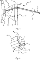
- the figures 1 and 2 illustrate an example of a first embodiment of a road lighting system 1 according to the invention. These figures also make it possible to illustrate the general principle of the invention.
- Such a lighting system 1 is intended to be integrated into a lighting device, in particular a vehicle headlamp, in particular that illustrated in figure 5 .
- the lighting system 1 comprises an optical element 10 having a controlled caustic-generating surface 12 .
- This generating surface 12 can be a reflecting surface or a refracting surface, as illustrated in figure 1 and 2 .
- This optical element is hereinafter called caustic generator 10.
- the generating surface 12 extends according to a given overall shape 13, represented by the vertical dotted line in figures 1 and 2 .
- the caustic generator 10 is a transparent plate having an input face 11 and an output face.
- the input face 11 is arranged opposite a beam generator 3 of light rays so as to receive the rays r 1 , r 2 , r 3 emitted by the beam generator 3.
- the output face is arranged to receive the rays r 1 , r 2 , r 3 refracted by the entrance face 11.
- the output face may be formed, in particular entirely, by the generating surface 12.
- the generating surface 12 has local variations in shape around the overall given shape 13. These local variations are distributed over the whole of the generating surface 12, so that they give the whole of the generating surface 12 a relief forming an object pattern.
- these local variations form hollows and bumps on the output face of said caustic generator 10.
- these different local variations are arranged so that the majority of said generating surface 12 is smooth.
- this surface is differentiable at any point. In other words, on smooth areas, it has no protruding or re-entrant edge.
- these different local variations are arranged so that for the beam of rays r 1 , r 2 , r 3 incident on the whole of said generating surface 12, these rays r 1 r 2 , r 3 having a known given distribution, the generating surface 12 deflects the rays r 1 , r 2 , r 3 according to different orientations depending on the local variations they encounter, thus forming a deflected beam propagating a light pattern over a useful interval s extending upstream of and at least up to a finite given optimal propagation distance, hereinafter optimal distance, this propagated pattern corresponding to a distorted projection of the object pattern.
- This generating surface 12 corresponds to a controlled caustic generating surface.
- this pattern In the case of a swimming pool, this pattern generally propagates over a distance of 3 meters. The propagated pattern is therefore observable by projecting onto the background of the swimming pool, whether the bottom is 1.5 m or 2 m. This background therefore forms the screen on which the caustic forming the propagated pattern is observable.
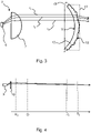
- the light pattern propagates at least over a given optimal distance. Beyond this optimum distance D p , the rays of the deflected beam intersect.
- this optimal distance D p can be infinite, the rays not crossing, or finite, as can be seen in the block diagram in figure 4 . If, as in the example shown, a vertical screen is interposed at an intermediate distance D 1 , for example 25 meters, from the lighting system or at another intermediate distance D 2 , for example 70 meters, the optimum distance D p being greater than these intermediate distances, the same more or less distorted pattern will be observed.
- this optimal distance D p is that at which the pattern will have the best sharpness.
- the generating surface can thus be designed with respect to this definition.
- This minimum distance D 0 may also exist a minimum distance D 0 below which the pattern is not formed. This minimum distance D 0 is generally quite small. In the example illustrated, this minimum distance D 0 is less than 1 meter.
- the pattern is not lost as soon as the rays intersect but afterwards, at a greater maximum distance (not shown).
- the useful interval comprises a downstream portion, going from the optimum distance D p , to this maximum distance and an upstream portion, going from the minimum distance D 0 to the optimum distance D p .
- this downstream portion can be of a different value from that of the upstream portion. In particular, it may be less than it by more than half.
- the value of the upstream portion would be 69 meters, and the downstream portion could be less than 34.5 meters.
- said caustic generator 10 and its local variations are arranged so that the propagated pattern corresponds to a light distribution of a portion of an illuminating beam.
- a projected pattern called the target pattern, corresponding to the photometry of a part of the lighting beam, for example as in figure 7a or 7b .
- the optimal distance D p is greater than or equal to 70 meters.
- the lighting system can be arranged so that the target pattern is projected onto the road, which forms a target surface located at a distance within the useful range. This target pattern will then be stretched in relation to a target pattern which would be projected on a screen at 25 meters.
- the given distribution can correspond to radii r 1 , r 2 , r 3 that are substantially parallel, as illustrated in picture 3 , or, as shown in figures 1 and 2 , substantially distributed globally along an emission cone 14, in particular as with a diverging light source, such as an LED.
- a diverging light source such as an LED
- the given distribution is such that for any plane perpendicular to the direction of propagation, at a given point of this plane, the incident ray(s) at this point come(nen )t of a single direction. Indeed, the distribution of the rays emitted by an LED corresponds substantially to such a given distribution.
- the lighting system 1 and/or the lighting device comprising it can be delivered without the beam generator 3, but has a mounting part 2 on which it is intended to be mounted, so that the rays r 1 , r 2 , r 3 are incident on said generating surface 12.
- this mounting part 2 and the beam generator 3 can be arranged so that, on mounting, the beam emitted by the beam generator 3 has a given overall direction with respect to said caustic generator 10. Thus, it does not there is no need for the assembly to adjust this orientation so that it corresponds to the layout allowing to generate the target pattern.
- the beam generator 3 is mounted on the mounting part 2.
- the beam generator 3 can, as here, be formed by a light-emitting diode or LED.
- FIG 1 is shown schematically a light-emitting element 4 of the LED with, attached to it, a protective dome 5 transparent.
- the optical element 10 is curved.
- the principle is nevertheless identical and the local variations are arranged so as to take account of the shape of the optical element 10 so as to form the lighting beam.
- the same references are therefore used for the elements of the lighting system.
- the figures 5 and 6 illustrate a projector 40 comprising a housing 48 closed by a glass 49 of transparent closure.
- the lighting system 41 and the basic optical module 42 respectively emit a first beam part and a second beam part.
- the figures 7a to 7c respectively illustrate the projections of the first part of the beam 20, of the second part of the beam 30, and of a global beam 50 obtained by projecting the first part of the beam 20 and the second part of the beam 30 together.
- the figures 7a to 7c illustrate these projections on a vertical screen, placed at a distance D 1 less than the optimal distance D p , for example at 25 meters as in figure 4 .
- a horizontal axis H symbolizes the horizon and represents the coordinate axis according to a horizontal position. It crosses a vertical axis V, which represents the coordinate axis according to a vertical position.
- the horizon is at 0° vertically and the longitudinal axis of the vehicle and the direction according to the crossing point of these axes H, V is at 0° vertically and 0° horizontally.
- the overall beam 50 is here a dipped beam. It therefore has an upper cutoff 51 making it possible not to dazzle the drivers of vehicles being followed or arriving in the opposite direction. This cut 51 nevertheless makes it possible to illuminate the roadside in the direction in which the vehicle intended to be fitted with the headlight 40 is traveling.
- a dotted rectangle illustrates a central zone 52 delimited in width between -10 and +10° and in height between -2 and +2°.
- the global beam 50 is essentially formed by the first beam part 20, whereas outside this central zone 52, the global beam 50 is essentially formed by the second beam part 30 .
- the input face 11 of the caustic generator 10 is arranged opposite a beam generator 3 of light rays so as to receive the rays it emits.
- the output face of the caustic generator 10 is arranged to receive the rays refracted by the input face 11.
- the output face is formed, in particular entirely, by the generating surface 12.
- the entry face 11 can be flat as here and the generating surface 12 can have the overall shape of a dish, so as to confer to the caustic generator 10 a form of lens.
- the caustic generator 10 could be such as those illustrated in figures 1 to 3 .
- the generating surface 12 refracts the rays, shown in dotted lines, so as to form according to the principle of the invention the propagated pattern illustrated in figure 7a .
- the photometric distribution of this propagated pattern 20 is that of a central part of the dipped headlight.
- the basic optical module 42 can for example be an elliptical module with a cover. It is arranged in such a way as to form the part of the global beam 50 outside the central zone 52.
- the basic optical module 42 is arranged so as to form, as illustrated in figure 7b , the second beam part 30 with a greater extent than that of the first beam part 20, as well as with a photometric distribution corresponding to that of a passing beam outside the central zone 52 (not shown in figure 7b ), and a cut 31 around this central zone 52.
- the first and the second beam part 20, 30 may overlap slightly at the level of the cut-off 31 of the second beam part 30.
- the area of overlap is called overlapping portion 54.
- the generating surface 12 is here arranged so as to produce a light transition between the central portion 53 and the superposition portion 54.
- the generating surface 12 is also arranged so as to produce a light transition between this superposition portion 54 and the rest of the second beam part 30.
- these light transitions are carried out in such a way that the superposition zone 54 is not distinguishable in the global beam 50, and in particular that the latter is devoid of a light line in excess intensity compared to the rest of the global beam 50.
- the generating surface 12 can be arranged so that fewer rays are directed to form the lower portion 55.
- the figure 8 schematically illustrates the relief formed by the local variations of the generating surface 12. This relief forms an object pattern corresponding to a distorted shape 16 of the propagated pattern forming the first beam part 20.
- This embodiment thus makes it possible to produce a passing beam with, in its central portion 53, a cutoff, the oblique portion 22 and the first horizontal portion 21 of which are sharp and devoid of chromaticism.
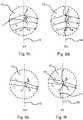
- the methods for calculating the generating surface 12 can for example follow the method illustrated in figures 9a to 9f .
- the overall shape of the generating surface 13 is symbolized by a dotted line.
- the screen at 70 meters is symbolized by a block on the surface 19 of which the first beam part 20 is projected and on which the propagated pattern is defined, which therefore forms on this screen 19 the target pattern for the calculation.
- the upstream step E1 takes into account the distribution of the rays on their arrival at the level of the overall given shape 13.
- the latter has the shape of a cup.
- other shapes are possible.
- the simplest case, not shown, is that of an optical element 10, such as that illustrated in figures 1 and 2 , formed of a transparent plate whose entry face 11 and the given overall shape 13 of the generating surface 12 are flat, and with a beam generator 3, such as that of the picture 3 , emitting parallel rays.
- the beam generator 3 and said caustic generator 10 are arranged so that the rays are perpendicular to the entry face 11. These rays are therefore not deflected before meeting the exit surface on which the generating surface is formed.
- the mode of realization of figures 1 and 2 is an intermediate case where the rays are distributed in an initial cone 14 at the exit of the beam generator 3, then refracted by the plane entry face, thus remaining inscribed in a cone, allowing an easy determination of the angle of incidence of the rays r 1 , r 2 , r 3 , r 4 , r 5 with the overall shape 13, and therefore an easy determination of the angle of incidence of the rays r 1 r 2 , r 3 , r 4 , r 5 with the generating surface 12.
- the embodiment of the picture 3 is another intermediate case where the distribution of the rays r 1 , r 2 , r 3 is initially simpler, since they are parallel at the output of the beam generator 3. On the other hand, they are then refracted differently by the input face 11 because it is curved, for example cylindrical of circular or elliptical section. However, this curvature being defined, it makes it possible to determine the orientation of the rays r 1 , r 2 , r 3 on their arrival at the given overall shape 13 of the generating surface 12, which is also curved.
- the optical element is a curved transparent plate, the input face 11 and the overall shape 13 of the generating surface 12 of which are cylindrical.
- the beam generator 3 may comprise a light source 6, such as a light-emitting diode, and a collimating lens 7 whose diopters make it possible to orient the rays parallel.
- this correlation step makes it possible to determine which object points p 1 , p 2 , p 3 , p 4 , p 5 of the given overall shape 13 are associated with which target points p′ 1 , p′ 2 , p′ 3 , p' 4 of the surface 19 of the screen.
- the orientation of the rays r 1 , r 2 , r 3 , r 4 , r 5 on arrival at the given overall shape 13 of the generating surface 12 is known.
- the orientation of the rays r 1 , r is determined 2 , r 3 , r 4 , r 5 from this given global shape 13 to join the object points p 1 , p 2 , p 3 , p 4 , p 5 to the target points p′ 1 , p′ 2 , p′ 3 , p' 4 with which they are correlated.
- Descartes' laws also known as Snell's laws in certain English-speaking countries, or even under the name of Snell-Descartes' laws.
- a sub-step E4 illustrated in figures 9c and 9e , for an object point p 1 , p 2 , p 3 , p 4 , p 5 of the given global shape 13 or of the generating surface calculated previously, with the direction of arrival and the direction of departure of the rays r 1 r 2 , r 3 , r 4 , r 5 , we can determine the tangent you and normal not of the exit surface at this point so that the latter deflects each ray r 1 r 2 , r 3 , r 4 , r 5 incident on arrival along the corresponding direction of refraction.
- the set of normals not also called fields of the normals
- the figures 9c and 9d illustrate the realization of these two sub-steps in an enlargement at the level of the object points p 1 , p 2 , p 3 , not referenced on the figures 9c and 9d to clarify more.
- the figures 9e and 9f illustrate the realization of these two sub-steps in an enlargement at the level of the object points p 4 , p 5 not referenced on the figures 9e and 9f to clarify more.
- this generating surface 12 includes deviations from the overall shape 13 and forms hollows and bumps.
- the amplitude of a local variation can in this application be defined as the distance between the local variation and said global shape 13 according to the normal at a given point of the global shape 13.
- any point of the given overall shape can be defined by a dimension along a single direction z perpendicular to this overall shape 13.
- the generating surface 12 can be arranged, and therefore calculated, so that, for the majority of the generating surface 12, namely on smooth portions representing the majority of this surface, the transition from a local variation to the else be smooth. This is particularly the case for the portion illustrated in picture 2 , and the one illustrated in figure 9d .
- the generating surface 12 can also be arranged so that, for these smooth portions, local variations are smooth.
- one of the smooth portions may have a surface representing the majority of the generating surface.
- a first example of a calculation method can be used to calculate this generative surface 12. This is the method disclosed in the document Yue et al. [1]. This document indicates in particular the various steps for constructing the generating surface 12 from a given example, in particular for establishing the relationship between the points of the generating surface 12 and those of the surface 19 of the screen.
- This first example of a method makes it possible to obtain a totally smooth generating surface 12 . Switching from one local variation to another is smooth.
- the cutoff of the first part of the beam 20 is sharp enough to be used to form the central portion 53 of a dipped beam.
- This method can for example be used to produce the generating surface 12 of the first embodiment. It could also be used in the third embodiment of the figures 5 and 6 .
- this second method no bijection constraint is used in the correlation step.
- This method is more complex but makes it possible to obtain a higher contrast, namely a ratio between the light zone and the dark zone.
- This method in fact makes it possible to obtain darker zones than those of the method of Yue and Al, mentioned previously.
- this second method it is possible with this second method to obtain more marked demarcations between dark zone and light zone.
- the portions outside the edges are smooth, the transition from one local variation to the other being smooth there.
- the method used does not impose a bijection constraint to establish the target pattern.
- several object points p 1 , p 2 correspond to a single target point p′ 1 .
- the generating surface 12 has a slope variation discontinuity, corresponding to an outgoing edge 18 on the generating surface 12, and therefore re-entrant in the direction of the incident rays.
- the local variations on either side of this edge 18 make it possible to concentrate the rays r 1 , r 2 on a line of the screen 19, including in particular the point p′ 1 , to form the cut there.
- the correlation step E3 resulted, without however having constrained it, in a one-to-one relationship between the corresponding object points p 3 , p 4 , p 5 and the corresponding target points p′ 2 , p′ 3 , p′ 4 .
- each point of the generating surface 12 is therefore associated with an amplitude which corresponds to a deviation from the global shape 13, this amplitude being defined according to a direction parallel to the normal to the global shape 13 at this point. .
- this rectangle 17 can have a side at least four times greater, in particular six times greater than that of the amplitude of each local variation with respect to the global shape given 13 at the level of this local variation, therefore greater than six times the maximum amplitude.
- the local variations can present a tangent you forming an angle ⁇ with the overall shape given between -60 and 60 degrees, in particular between -30 and 30 degrees.
- the side of the rectangle 17 in which the caustic generator 10 is circumscribed may be at least ten times greater, in particular thirty times, than that of one side of this light source 3, 6, in particular when this source is a diode electroluminescent.
- FIG. 1 The three embodiments of figures 1 to 3 and 5 and 6 refer to caustic generators 10 operating by refraction.
- the generating surface 12 is formed on an optical element 10 specially dedicated for this purpose. However, it can also be formed on elements having other functions, such as a lens for closing the lighting device, an optical lens, a mask.
- mask denotes the trim intended to mask certain elements, such as cables, the bottom of the case. It is also called “ bezel” in English.
- the figures 1 to 3 and 6 illustrate cases where the generator surface 12 is on the output face of the caustic generator 10.
- the optical element may have a generator surface on the input face and /or on the exit face.
- the figure 10 illustrates a fourth embodiment, which is a variant of the lighting system 41 of the third embodiment.
- the figure 5 can therefore also be applied to this fourth embodiment.
- the light source here formed by an LED 6
- an optic 7 making it possible to orient the rays r1, r2, r3 substantially parallel, here perpendicular to the input face 11 of the generator caustic 10.
- This lens is in this example a reflector 7 of paraboloid shape.
- the LED 6 is arranged between the reflector 7 and the caustic generator 10 in the form of a lens.
- the reflector 7, the LED 6 and the caustic generator 10 are interconnected mechanically so as to form a complementary optical module 41.
- This complementary optical module thus has the appearance of an elliptical module. This makes it possible to produce a headlight 40 with a more harmonious appearance by assembling the complementary optical module 41 with a basic optical module 42 which is an elliptical module.
- the figure 11 illustrates a fifth embodiment, according to which the optical element 10' or caustic generator 10' operates by reflection.
- the caustic generator 10' is here a mirror, the reflecting surface of which forms the generating surface 12', presenting local variations around its planar overall shape 13'.
- This mirror 10' can have one or more edges.
- a re-entrant edge 18' namely forming the bottom of a hollow, delimiting portions of surfaces with an orientation facing each other, these portions thus allowing create a luminous line marking the cut of a global beam.
- the upstream step is simplified because the rays r 1 , r 2 , r 3 , r 4 arrive directly on the generating surface 12 according to the given distribution and also leave it directly.
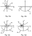
- the figures 12a to 12d illustrate the beams obtained by a sixth embodiment which is an alternative embodiment of the projector 40 of the figures 5 and 6 .
- the schematic illustration of the figure 5 can therefore be used for this sixth embodiment.
- This embodiment differs by its complementary module formed by the lighting system 41 according to the invention and by its basic optical module 42, which are here arranged so as to respectively form a first part of beam 60 and a second part of beam 70 different from that of the third embodiment.
- global beam 80 resulting from the superposition of the two beam parts 60, 70 forms an adaptive main beam.
- the figures 12a to 12d respectively illustrate the projections of the first part of beam 60, of the second part of beam 70, and of the global beam 50 on a vertical screen, placed at a distance less than the optimal distance D p , for example placed at a distance of 25 meters.
- the second beam part 70 comprises a plane upper cut-off and is, for example, formed by means of an elliptical module with a mask or a module with a reflector, in particular of the parabolic type. Its distribution photometric corresponds to the photometric distribution located below a horizontal line located vertically at 2° in a high beam.
- cut portions 61, 62, 63 delimit a dark zone 64.
- the projector 40 is equipped with actuators, not shown, which make it possible to move the complementary optical module 41 along a vertical axis of rotation, and therefore the first part of the beam 60 horizontally, while the second part of the beam 70 remains fixed relative to the projector. 40.
- the vehicle fitted with the headlight 40 When the vehicle fitted with the headlight 40 is fitted with sensors, for example a camera, a computer allowing image processing, and a processor, the latter can control the actuators so as to move the complementary optical module 41 so that the dark zone 64 is arranged at the level of a vehicle C coming in the opposing direction, as in figure 12d , or followed. This provides more powerful lighting than a dipped beam, while avoiding dazzling other drivers.
- the first part of the beam 60 and the second part of the beam 70 can overlap along a superposition portion 72.
- the generating surface 12 can also be arranged so as to achieve the light transitions previously described.
- the propagated and/or target patterns represented are in the context of right-hand traffic. For left-hand circulation, these must simply be reversed symmetrically with respect to the vertical axis V.
Description
La présente invention se rapporte au domaine des dispositifs d'éclairage de véhicule présentant une coupure, soit une ligne de démarcation nette entre la zone éclairée et la zone sombre.The present invention relates to the field of vehicle lighting devices having a cut-off, ie a clear line of demarcation between the lighted area and the dark area.
L'une des techniques classiques pour obtenir un tel faisceau, tel qu'un faisceau de croisement, est un module optique comprenant un réflecteur elliptique et une lentille convergente. Une source de lumière est placée au premier foyer du réflecteur elliptique et le foyer de la lentille convergente est placé au deuxième foyer du réflecteur elliptique. Pour réaliser la coupure du faisceau, on place un cache qui fait obstacle à une partie des rayons au niveau du foyer. De ce fait le faisceau projeté présente une coupure dont la forme correspond à celle du cache.One of the conventional techniques for obtaining such a beam, such as a passing beam, is an optical module comprising an elliptical reflector and a converging lens. A light source is placed at the first focus of the elliptical reflector and the focus of the converging lens is placed at the second focus of the elliptical reflector. To cut the beam, a cover is placed which obstructs part of the rays at the focal point. As a result, the projected beam has a cut whose shape corresponds to that of the mask.
Un des problèmes de ce type de module optique est que le cache génère un chromatisme au niveau de la coupure du faisceau. Autrement dit, au niveau de la coupure, on observe une coloration de cette dernière, en particulier une ligne rouge et une ligne bleue superposées. Le document
Il existe également des solutions techniques comprenant uniquement un réflecteur, notamment construit à partir de sections paraboliques, permettant de réaliser un tel faisceau.There are also technical solutions comprising only a reflector, in particular constructed from parabolic sections, making it possible to produce such a beam.
Le problème technique que vise à résoudre l'invention est donc de réaliser un dispositif d'éclairage employant une solution alternative permettant de générer un faisceau d'éclairage à coupure avec un chromatisme restreint, voire sans chromatisme.The technical problem which the invention aims to solve is therefore to produce a lighting device employing an alternative solution making it possible to generate a cut-off lighting beam with limited chromatism, or even without chromatism.
Pour résoudre ce problème, la demanderesse a eu l'idée d'utiliser des caustiques.To solve this problem, the applicant had the idea of using caustics.
Les caustiques sont un phénomène optique connu depuis longtemps. Elles sont par exemple observables au fond d'une piscine éclairée par le soleil. Elles y forment des motifs fluctuants formant globalement un maillage de lignes de lumière plus concentrées et donc plus lumineuses, avec entre les mailles des zones plus sombres. Ces lignes et zones sombres sont dues aux différentes fluctuations de la surface de l'eau. Ces fluctuations forment localement des variations d'orientation autour de la forme globalement plane de la surface de l'eau. Ainsi, en fonction des variations locales rencontrées, les rayons vont être déviés différemment, certains se rapprochant et formant les lignes plus concentrées et donc plus lumineuses, et d'autres s'écartant et formant les zones sombres. Le maillage varie en fonction de l'agitation de la surface.Caustics are an optical phenomenon that has been known for a long time. They are for example observable at the bottom of a swimming pool lit by the sun. They form fluctuating patterns there, generally forming a mesh of more concentrated and therefore brighter lines of light, with darker zones between the meshes. These dark lines and areas are due to the different fluctuations of the water surface. These fluctuations locally form variations in orientation around the generally flat shape of the water surface. Thus, depending on the local variations encountered, the rays will be deflected differently, some approaching and forming more concentrated and therefore brighter lines, and others deviating and forming dark areas. The mesh varies according to the agitation of the surface.
Depuis quelques années, des chercheurs se sont intéressés à des méthodes pour utiliser ce phénomène sur des surfaces fixes présentant des variations locales, de manière à générer des caustiques complexes de forme contrôlée. Notamment, ils ont développé différentes méthodes pour calculer des surfaces réfractrices formées d'un matériau transparent avec une distribution et un agencement de variations locales, de manière à ce que, lorsque ces surfaces réfractrices sont éclairées, celles-ci permettent, à partir d'une source de lumière donnée, de former un motif sur un écran.In recent years, researchers have been interested in methods to use this phenomenon on fixed surfaces with local variations, so as to generate complex caustics of controlled shape. In particular, they have developed different methods for calculating refracting surfaces formed of a transparent material with a distribution and arrangement of local variations, so that when these refracting surfaces are illuminated, these allow, from a given light source, to form a pattern on a screen.
Dans certains travaux, ce motif, dit motif cible, correspond physiquement à une image distordue du motif que forment en relief les variations locales, dit motif objet.In some works, this pattern, called the target pattern, physically corresponds to a distorted image of the pattern formed in relief by the local variations, called the object pattern.
La demanderesse c'est aperçu que de telles surfaces pouvaient être utilisées dans des dispositifs lumineux de véhicule.The applicant realized that such surfaces could be used in vehicle lighting devices.
Ainsi, l'invention se rapporte à des systèmes et des dispositifs d'éclairage, notamment à des parties de projecteurs ou à des projecteurs, dans lesquels une surface génératrice de caustique contrôlée dévie les rayons lumineux d'une source de lumière, cette surface génératrice présentant des variations locales agencées de manière à former un faisceau d'éclairage avec au moins une coupure.Thus, the invention relates to lighting systems and devices, in particular to parts of headlights or to headlights, in which a controlled caustic-generating surface deflects the light rays from a light source, this generating surface having local variations arranged so as to form an illuminating beam with at least one cut.
A cet effet, un premier objet de l'invention est un système d'éclairage de la route de véhicule comprenant :
- un élément optique présentant une surface génératrice de caustique contrôlée, cette surface génératrice étant une surface réfléchissante ou réfractrice, s'étendant selon une forme globale donnée et présentant des variations locales de forme autour de cette forme globale donnée, ces variations locales étant réparties sur l'ensemble de ladite surface génératrice de sorte qu'elles confèrent à l'ensemble de la surface génératrice un relief formant un motif objet, ces différentes variations locales étant agencées de manière à ce que la majorité de ladite surface génératrice soit lisse et de manière à ce que pour un faisceau de rayons incidents sur l'ensemble de cette dite surface génératrice, ces rayons ayant une répartition donnée, ladite surface génératrice dévie les rayons selon des orientations différentes en fonction des variations locales qu'ils rencontrent, formant ainsi un faisceau dévié propageant un motif propagé, ce motif propagé correspondant à une forme distordue du motif objet,
- une partie de montage sur laquelle est destiné à être monté un générateur de faisceau de rayons selon la répartition donnée, de manière à ce que les rayons soient incidents sur ladite surface génératrice,
l'élément optique étant agencé de manière à ce que le motif propagé soit propagé sur un intervalle utile s'étendant en amont de et au moins jusqu'à une distance optimale de propagation donnée et selon une répartition photométrique donnée, de manière à former une partie d'un faisceau lumineux d'éclairage, cette partie présentant une coupure.
- an optical element having a controlled caustic-generating surface, this generating surface being a reflecting or refracting surface, extending according to a given overall shape and having local variations of shape around this given overall shape, these local variations being distributed over the the whole of said generating surface so that they give the whole of the generating surface a relief forming an object pattern, these different local variations being arranged in such a way that the majority of the said generating surface is smooth and so as to that for a beam of rays incident on the whole of said generating surface, these rays having a distribution given, said generating surface deflects the rays according to different orientations according to the local variations which they encounter, thus forming a deflected beam propagating a propagated pattern, this propagated pattern corresponding to a distorted form of the object pattern,
- a mounting part on which a ray beam generator is intended to be mounted according to the given distribution, so that the rays are incident on said generating surface,
the optical element being arranged so that the propagated pattern is propagated over a useful interval extending upstream from and at least up to a given optimal propagation distance and according to a given photometric distribution, so as to form a part of an illuminating light beam, this part having a cut.
Dans la demande, on entend par « lisse » une zone dérivable en tout point, autrement dit une zone dépourvue d'arête saillante ou rentrante. Une portion est lisse lorsque sensiblement l'ensemble des points formant celle-ci obéit à cette définition.In the application, the term “smooth” means a zone derivable at any point, in other words a zone devoid of any protruding or re-entrant edge. A portion is smooth when substantially all of the points forming it obey this definition.
Ainsi, il est possible de monter un générateur de faisceau lumineux, qu'une source de lumière ou une source de lumière et un ensemble d'un ou plusieurs éléments optiques, permettant de générer des rayons selon une répartition donnée, ce montage se faisant de manière à ce que ces rayons soient incidents sur l'élément optique. De ce fait, l'allumage du générateur de faisceau permettra la génération du motif propagé, qui se propagera en avant du véhicule.Thus, it is possible to mount a light beam generator, a light source or a light source and a set of one or more optical elements, making it possible to generate rays according to a given distribution, this mounting being done so that these rays are incident on the optical element. Therefore, the ignition of the beam generator will allow the generation of the propagated pattern, which will propagate in front of the vehicle.
Ces générateurs de faisceau peuvent être simples. L'élément optique suffit en lui-même à modifier le faisceau pour en faire un motif lui conférant la photométrie requise pour l'éclairage de la route.These beam generators can be simple. The optical element is sufficient in itself to modify the beam to form a pattern giving it the photometry required for lighting the road.
De plus, contrairement aux solutions avec cache, dans le système d'éclairage selon ce premier objet, l'essentiel, voire la totalité, des rayons lumineux rencontrant la surface génératrice sont déviés et forment le motif cible. La luminosité du motif cible est donc supérieure avec le dispositif d'éclairage selon ce premier objet.Moreover, unlike the solutions with mask, in the lighting system according to this first object, most, if not all, of the light rays encountering the generating surface are deflected and form the target pattern. The luminosity of the target pattern is therefore greater with the lighting device according to this first object.
On entend par distance optimale de propagation donnée, la distance à laquelle la majorité des rayons déviés et formant le motif cible se croisent. C'est à cette distance que ce motif a la meilleure netteté. La surface génératrice peut ainsi être conçue aisément par rapport à cette définition. Cette distance optimale de propagation donnée est dite ci-après distance optimale. La répartition photométrique est donc optimale à cette distance.By given optimal propagation distance is meant the distance at which the majority of the deflected rays and forming the target pattern intersect. It is at this distance that this pattern has the best sharpness. The generating surface can thus be designed easily with respect to this definition. This optimal distance of given propagation is hereinafter referred to as optimum distance. The photometric distribution is therefore optimal at this distance.
Par ailleurs, cette répartition photométrique reste suffisamment conservée à l'intérieur de l'intervalle utile pour former le faisceau d'éclairage.Furthermore, this photometric distribution remains sufficiently preserved within the useful interval to form the illuminating beam.
Le système d'éclairage selon l'invention peut optionnellement comprendre une ou plusieurs des caractéristiques suivantes :
- la distance optimale est supérieure ou égale à 70 mètres ; cela permet de réaliser une partie de faisceau d'éclairage qui conservera la photométrie du faisceau sur une distance permettant de réaliser une partie de faisceau d'éclairage plus efficace, notamment un feu de croisement ; notamment, pour réaliser le faisceau de croisement, le système d'éclairage peut être agencé dans le véhicule de manière à ce que le motif propagé rencontre la surface de la route à 70 mètres ;
- la distance optimale est supérieure ou égale à 150 mètres ;
- la coupure présente au moins deux portions orientées selon des directions différentes l'une de l'autre ; cela permet de réaliser un faisceau avec une portion non éblouissante et une portion éblouissante ;
- la répartition donnée est sensiblement telle que pour tout plan transversal, notamment perpendiculaire, à la direction de propagation, en un point donné de ce plan, le ou les rayon(s) incident(s) en ce point provien(nen)t d'une unique direction ;
- selon la répartition donnée, les rayons sont sensiblement parallèles ou sensiblement répartis dans un cône d'émission ;
- la répartition donnée correspond à celle d'une diode électroluminescente ;
- le système d'éclairage comprend le générateur de faisceau de rayons selon la répartition donnée ; le système d'éclairage est ainsi prêt à émettre ;
- la surface génératrice comprend au moins une portion lisse dont la surface représente la majorité de la surface génératrice, le passage d'une variation locale à l'autre étant lisse à l'intérieur de cette portion lisse ; cela permet de plus de moins déformer l'image des pièces en amont de l'élément optique et visibles derrière cette portion, tout en permettant de visualiser leur forme ;
- la majorité de la surface génératrice est agencée de manière à ce que chaque variation locale dévie les rayons de manière à former, à la distance optimale, une et une seule portion du motif propagé qui soit distincte des portions du motif propagé formées par les autres variations locales, et pour la majorité du motif cible, chaque portion du motif propagé, à la distance optimale, reçoit les rayons lumineux d'une et d'une seule variation locale ; on a ainsi, à la distance optimale, pour cette majorité de la surface génératrice et cette majorité du motif cible, une relation bijective entre chaque portion lisse du motif objet et chaque portion du motif propagé sans discontinuité marquée de luminosité ; cela simplifie le calcul et donc la réalisation de la surface génératrice ;
- toute la surface génératrice est lisse, le passage d'une variation locale à l'autre étant lisse ; cela permet de plus de moins déformer les pièces en amont de l'élément optique ; il est ainsi possible soit de distinguer ces pièces au travers de l'élément optique, lorsque l'élément optique est un élément transparent réfractant les rayons émis par ledit générateur de faisceau, soit en observant l'image de ces pièces sur l'élément optique, lorsque ce dernier est un réflecteur réfléchissant les rayons émis par ledit générateur de faisceau ; cela permet ainsi de travailler le style du générateur de faisceau ;
- la totalité de la surface génératrice est agencée de manière à ce que chaque variation locale dévie les rayons de manière à former une et une seule portion du motif propagé qui soit distincte des portions du motif propagé formées par les autres variations locales, et pour tout le motif propagé, chaque potion du motif propagé reçoit les rayons lumineux d'une et d'une seule variation locale ; on a ainsi une relation bijective entre la totalité du motif objet et chaque potion du motif propagé sans discontinuité marquée de luminosité ; cela simplifie le calcul et donc la réalisation de la surface génératrice ;
- le passage entre certaines variations locales est délimité par une arête, les variations locales de part et d'autre de cette arête étant agencées de manière à dévier une partie des rayons de manière à former au moins une portion de la coupure avec cette partie des rayons ; un tel passage crée une discontinuité dans les variations de pente sur la surface génératrice ; cela permet de créer une coupure encore plus nette ;
- les variations locales sont agencées de manières à ce que les rayons du faisceau dévié ne se croisent pas jusqu'à ladite distance optimale ; ainsi le motif propagé reste net sur une surface cible positionnée en amont de ou à la distance optimale ;
- selon l'alinéa précédent, il peut exister également une distance minimale en dessous de laquelle le motif n'est pas formé ; dans ce cas, le motif est net dans un intervalle, correspondant à l'intervalle utile, allant de cette distance minimale à au moins jusqu'à la distance de propagation ; par exemple, cet intervalle représente plus de la moitié de la distance optimale ;
- les variations locales présentent une tangente à la forme globale donnée formant un angle compris entre -60 et 60 degrés, notamment entre -30 et 30 degrés ; cela permet d'avoir une bonne transmission des rayons lumineux ;
- chaque variation locale présente, en chacun de ses points, une amplitude définie comme la distance entre la variation locale et ladite forme globale selon la normale en un point donné de la forme globale ;
- l'amplitude maximale de chaque variation locale est comprise dans un intervalle compris entre 0,001 millimètre (mm) et 1 mm ; cela confère un aspect plus lisse à la surface génératrice ;
- selon une direction globale de propagation du faisceau, l'élément optique est circonscrit dans un rectangle, dont un côté s'étendant selon une direction parallèle à cette direction de propagation est au moins quatre fois supérieur, notamment six fois supérieur à celui de l'amplitude de chaque variation locale par rapport à la forme globale donnée au niveau de cette variation locale ;
- selon une direction globale de propagation du faisceau, la surface génératrice est circonscrite dans un rectangle, dont un côté s'étendant selon une direction parallèle à cette direction de propagation est au moins dix fois supérieur, notamment trente fois, à celui d'un des côtés d'une source de lumière du générateur de faisceau ;
- le générateur de faisceau comprend une source de lumière, notamment une diode électroluminescente ; les diodes électroluminescentes sont particulièrement adaptées pour être couplées à une surface génératrice de caustique contrôlée ;
- le générateur de faisceau est formé par une diode électroluminescente émettant ses rayons globalement selon un cône ;
- le générateur de faisceau comprend une source de lumière, notamment une diode électroluminescente, et une optique agencée avec la source de lumière de manière à générer le faisceau de rayons selon la répartition donnée ;
- selon l'alinéa précédent l'optique est agencée avec la source de lumière de manière à générer le faisceau de rayons parallèles ;
- ladite optique est un réflecteur agencé de manière à réfléchir les rayons émis par la source de lumière vers la surface génératrice ;
- selon l'alinéa précédent, le réflecteur peut être du type parabolique ; le type parabolique comprend les réflecteurs construits à partir de paraboles, notamment les paraboloïdes et les réflecteurs formés de sections de paraboles ; c'est une manière simple de conférer aux rayons la répartition donnée notamment une répartition selon laquelle ils sont parallèles ;
- l'élément optique est formée d'un matériau transparent et est agencé avec le générateur de faisceau de manière à former le faisceau dévié par réfraction des rayons émis par le générateur de faisceau ; cela permet un agencement simple et un calcul simple de la surface génératrice ;
- la source de lumière est agencée entre le réflecteur et l'élément optique, le réflecteur, la source de lumière et l'élément optique étant reliés entre eux mécaniquement de manière à former un module optique ; le système d'éclairage peut ainsi être monté de manière autonome dans un véhicule, notamment dans un dispositif d'éclairage de véhicule, tel qu'un projecteur ;
- selon l'alinéa précédent, la surface génératrice peut être suffisamment lisse pour permettre de distinguer les formes des pièces placées à l'arrière de l'élément optique ;
- l'élément optique comprend une surface réfléchissante dont au moins une portion est formée par la surface génératrice ; autrement dit la surface génératrice est réfléchissante ; notamment, l'élément optique peut être un masque, notamment métallisé ; dans ce cas la surface génératrice peut former une portion de la surface de ce masque ; on peut ainsi conférer une autre fonction au masque, que celle de masquer certaines pièces du dispositif d'éclairage dans lequel est destiné à être monté le système d'éclairage ;
- l'élément optique est en un matériau transparent et est agencé avec le générateur de faisceau de manière à former le faisceau dévié par réfraction des rayons émis par le générateur de faisceau, l'élément optique comprenant une face d'entrée desdits rayons agencée en vis-à-vis du générateur de faisceau et une face de sortie de ces rayons agencée à l'opposé de ladite face d'entrée, la surface génératrice étant formée sur la face d'entrée ou sur la face de sortie ;
- selon l'alinéa précédent, l'élément optique comprend deux surfaces génératrices, une première surface génératrice étant formée sur la face d'entrée et une deuxième surface génératrice étant formée sur la face de sortie, ces deux surfaces génératrices étant agencées ensemble de manière à former le motif propagé et à assurer sa propagation sur l'intervalle utile ; cela permet de laisser plus de liberté dans les pentes à conférer aux variation locales ; de plus cela peut également permettre d'obtenir un meilleur contraste, ou bien d'augmenter la profondeur de champ, voire tendre vers une profondeur de champ infinie.
- the optimal distance is greater than or equal to 70 meters; this makes it possible to produce a part of the lighting beam which will retain the photometry of the beam over a distance making it possible to produce a part of the lighting beam that is more efficient, in particular a dipped beam; in particular, to produce the dipped beam, the lighting system can be arranged in the vehicle so that the propagated pattern meets the surface of the road at 70 meters;
- the optimal distance is greater than or equal to 150 meters;
- the cut has at least two portions oriented in different directions from each other; this makes it possible to produce a beam with a non-dazzling portion and a dazzling portion;
- the given distribution is substantially such that for any transverse plane, in particular perpendicular, to the direction of propagation, at a given point of this plane, the incident ray(s) at this point come(s) from a single direction;
- depending on the given distribution, the rays are substantially parallel or substantially distributed in an emission cone;
- the distribution given corresponds to that of a light-emitting diode;
- the lighting system comprises the ray beam generator according to the given distribution; the lighting system is thus ready to transmit;
- the generating surface comprises at least one smooth portion, the surface of which represents the majority of the generating surface, the passage from one local variation to the other being smooth inside this smooth portion; this also makes it possible to deform the image of the parts upstream of the optical element and visible behind this portion less, while making it possible to view their shape;
- the majority of the generating surface is arranged so that each local variation deflects the rays so as to form, at the optimum distance, one and only one portion of the propagated pattern which is distinct from the portions of the propagated pattern formed by the other variations locales, and for the majority of the target pattern, each portion of the propagated pattern, at the optimum distance, receives the light rays of one and only one local variation; there is thus, at the optimum distance, for this majority of the generating surface and this majority of the target pattern, a one-to-one relationship between each smooth portion of the object pattern and each portion of the propagated pattern without marked discontinuity of luminosity; this simplifies the calculation and therefore the production of the generating surface;
- the entire generating surface is smooth, the transition from one local variation to another being smooth; this also makes it possible to deform the parts upstream of the optical element less; it is thus possible either to distinguish these parts through the optical element, when the optical element is a transparent element refracting the rays emitted by said beam generator, or by observing the image of these parts on the optical element , when the latter is a reflector reflecting the rays emitted by said beam generator; this thus makes it possible to work on the style of the beam generator;
- the whole of the generating surface is arranged in such a way that each local variation deflects the rays so as to form one and only one portion of the propagated pattern which is distinct from the portions of the propagated pattern formed by the other local variations, and for all the propagated pattern, each potion of the propagated pattern receives the light rays of one and only one local variation; there is thus a one-to-one relation between the totality of the object motif and each potion of the propagated motif without marked discontinuity of luminosity; this simplifies the calculation and therefore the production of the generating surface;
- the passage between certain local variations is delimited by an edge, the local variations on either side of this edge being arranged so as to deflect a part of the rays so as to form at least a portion of the cut with this part of the rays ; such a passage creates a discontinuity in the slope variations on the generating surface; this makes it possible to create an even sharper cut;
- the local variations are arranged in such a way that the rays of the deflected beam do not intersect until said optimum distance; thus the propagated pattern remains sharp on a target surface positioned upstream of or at the optimum distance;
- according to the preceding paragraph, there may also exist a minimum distance below which the pattern is not formed; in this case, the pattern is clear in an interval, corresponding to the useful interval, ranging from this minimum distance to at least up to the propagation distance; for example, this interval represents more than half of the optimal distance;
- the local variations have a tangent to the given overall shape forming an angle between −60 and 60 degrees, in particular between −30 and 30 degrees; this makes it possible to have good transmission of the light rays;
- each local variation has, at each of its points, an amplitude defined as the distance between the local variation and said global shape along the normal at a given point of the global shape;
- the maximum amplitude of each local variation is within an interval between 0.001 millimeter (mm) and 1 mm; this gives a smoother appearance to the generating surface;
- along an overall direction of propagation of the beam, the optical element is circumscribed in a rectangle, one side of which extending along a direction parallel to this direction of propagation is at least four times greater, in particular six times greater than that of the amplitude of each local variation with respect to the global shape given at the level of this local variation;
- along an overall direction of propagation of the beam, the generating surface is circumscribed in a rectangle, one side of which extending along a direction parallel to this direction of propagation is at least ten times greater, in particular thirty times, than that of one of the sides of a beam generator light source;
- the beam generator comprises a light source, in particular a light-emitting diode; the light-emitting diodes are particularly suitable for being coupled to a controlled caustic-generating surface;
- the beam generator is formed by a light-emitting diode emitting its rays generally according to a cone;
- the beam generator comprises a light source, in particular a light-emitting diode, and optics arranged with the light source so as to generate the beam of rays according to the given distribution;
- according to the preceding paragraph, the optics are arranged with the light source so as to generate the beam of parallel rays;
- said optical system is a reflector arranged to reflect the rays emitted by the light source towards the generating surface;
- according to the preceding paragraph, the reflector may be of the parabolic type; the parabolic type includes reflectors constructed from parabolas, in particular paraboloids and reflectors formed from sections of parabolas; it is a simple way of giving the rays the given distribution, in particular a distribution according to which they are parallel;
- the optical element is formed of a transparent material and is arranged with the beam generator so as to form the deflected beam by refraction of the rays emitted by the beam generator; this allows a simple arrangement and a simple calculation of the generating surface;
- the light source is arranged between the reflector and the optical element, the reflector, the light source and the optical element being interconnected mechanically so as to form an optical module; the lighting system can thus be mounted independently in a vehicle, in particular in a vehicle lighting device, such as a headlight;
- according to the preceding paragraph, the generating surface may be sufficiently smooth to make it possible to distinguish the shapes of the parts placed at the rear of the optical element;
- the optical element comprises a reflective surface of which at least a portion is formed by the generating surface; in other words, the generating surface is reflective; in particular, the optical element may be a mask, in particular metallized; in this case the generating surface can form a portion of the surface of this mask; it is thus possible to confer another function on the mask, than that of masking certain parts of the lighting device in which the lighting system is intended to be mounted;
- the optical element is made of a transparent material and is arranged with the beam generator so as to form the deflected beam by refraction of the rays emitted by the beam generator, the optical element comprising an entry face for said rays arranged in a screw -to-beam generator face and face output of these rays arranged opposite said input face, the generating surface being formed on the input face or on the output face;
- according to the preceding paragraph, the optical element comprises two generating surfaces, a first generating surface being formed on the input face and a second generating surface being formed on the output face, these two generating surfaces being arranged together so as to forming the propagated pattern and ensuring its propagation over the useful interval; this makes it possible to leave more freedom in the slopes to be conferred on the local variations; moreover, this can also make it possible to obtain a better contrast, or else to increase the depth of field, or even tend towards an infinite depth of field.
L'invention a également pour objet un dispositif d'éclairage de la route de véhicule comprenant un système d'éclairage selon l'invention.The invention also relates to a vehicle road lighting device comprising a lighting system according to the invention.
Ce dispositif d'éclairage peut par exemple être un projecteur avant, émettant un feu de croisement et/ou un feu longue portée, ou encore un projecteur antibrouillard.This lighting device can for example be a front headlight, emitting a dipped beam and/or a long-range headlight, or else a fog lamp.
Le dispositif d'éclairage selon l'invention peut optionnellement comprendre une ou plusieurs des caractéristiques suivantes :
- le dispositif d'éclairage peut être agencé de manière à ce qu'une fois monté sur le véhicule, le motif propagé soit projeté sur la route à une distance de projection donnée correspondant à la portée du faisceau d'éclairage, cette distance de projection étant à l'intérieur de l'intervalle utile, selon une orientation donnée du véhicule ; cela permet d'avoir un motif propagé respectant la photométrie donnée avec une coupure nette sur l'intervalle utile et d'éviter ainsi tout éblouissement des véhicules suivis ou des véhicules venant en sens opposé ;
- cette distance de projection peut être égale à la moitié de la distance optimale, lorsque la route est horizontale ; cela améliore la netteté de la coupure quelle que soit l'assiette du véhicule, notamment en montée, en descente, en cas de freinage ou en cas d'accélération ; cette distance de projection peut être également bien supérieure à la distance minimale, notamment au moins au double de celle-ci ;
- le dispositif d'éclairage comprend un boitier et une glace de fermeture du boitier au travers de laquelle sortent les rayons émis par le dispositif d'éclairage, la glace de fermeture formant l'élément optique, la surface génératrice étant formée en surface d'une portion de la glace de fermeture, le faisceau dévié étant formé par réfraction des rayons émis par le générateur de faisceau ; cela permet ainsi de propager le motif propagé à l'extérieur du véhicule et sans ajout d'une nouvelle pièce ;
- le dispositif d'éclairage comprend:
- o un système d'éclairage selon l'invention, agencé de manière à former une première partie de faisceau lumineux présentant une coupure avec au moins deux portions orientées selon des directions différentes l'une de l'autre,
- o un module optique de base agencé de manière à former une deuxième partie de faisceau lumineux plus étendue que la première partie de faisceau,
- le système d'éclairage et le module optique de base sont agencés de manière à ce que la première partie de faisceau se chevauchent partiellement à la deuxième partie de faisceau, la coupure étant à distance de la deuxième partie de faisceau ; on a ainsi un faisceau global sans discontinuité ;
- la surface génératrice peut être agencée de manière à :
- o réaliser une transition lumineuse entre d'une part la portion de la première partie de faisceau située entre la coupure de la première partie de faisceau et la deuxième partie de faisceau, et d'autre part, une portion du faisceau global, dite portion de superposition, où la première partie de faisceau se chevauche partiellement à la deuxième partie de faisceau, et/ou
- o réaliser une transition lumineuse entre cette portion de superposition et le reste de la deuxième partie de faisceau ;
- le système d'éclairage et le module optique de base sont agencés de manière à ce que la première partie de faisceau soit agencée au-dessus de la deuxième partie de faisceau, la coupure de la première partie de faisceau étant également au-dessus de la deuxième partie de faisceau ;
- le système d'éclairage et le module optique sont agencés de manière à ce que:
- o le faisceau global soit un faisceau de croisement,
- o la première partie de faisceau forme la portion centrale du faisceau global et comprenne la jonction entre une portion horizontale et une portion oblique de la coupure, notamment située de -10 à +10° selon l'horizontale et/ou de -2 à +2° selon la verticale, et
- o la deuxième partie de faisceau forme le reste du faisceau global ;
- le système d'éclairage et le module optique sont agencés de manière à ce que :
- o le faisceau global soit un faisceau route adaptatif,
- o la deuxième partie de faisceau forme une partie basse du faisceau global,
- o la première partie de faisceau forme une partie supérieure du faisceau global et présente une zone sombre centrale démarquée par une coupure avec des portions délimitant cette zone sombre en bas et sur les côtés,
- o le faisceau global présente cette zone sombre, le bas de la zone sombre étant agencé au-dessus de la deuxième partie de faisceau ;
- le dispositif d'éclairage comprend des actionneurs pour entrainer le système d'éclairage ou une partie du système d'éclairage en déplacement par rapport au module optique de base, de manière à entrainer le déplacement de la première partie de faisceau par rapport à la deuxième partie de faisceau.
- the lighting device can be arranged so that, once mounted on the vehicle, the propagated pattern is projected onto the road at a given projection distance corresponding to the range of the lighting beam, this projection distance being inside the useful interval, according to a given orientation of the vehicle; this makes it possible to have a propagated pattern respecting the given photometry with a clear cut over the useful interval and thus to avoid any dazzling of the vehicles followed or of the vehicles coming in the opposite direction;
- this projection distance can be equal to half the optimum distance, when the road is horizontal; this improves the sharpness of the cut regardless of the attitude of the vehicle, in particular uphill, downhill, in the event of braking or in the event of acceleration; this projection distance can also be much greater than the minimum distance, in particular at least twice the latter;
- the lighting device comprises a housing and a housing closing glass through which the rays emitted by the lighting device emerge, the closing glass forming the optical element, the generating surface being formed on the surface of a portion of the closing lens, the deflected beam being formed by refraction of the rays emitted by the beam generator; this thus makes it possible to propagate the propagated pattern outside the vehicle and without adding a new part;
- the lighting device includes:
- o a lighting system according to the invention, arranged so as to form a first part of the light beam having a cut-off with at least two portions oriented in different directions from each other,
- o a basic optical module arranged in such a way as to form a second part of the light beam which is larger than the first part of the beam,
- the lighting system and the basic optical module are arranged so that the first part of the beam partially overlaps the second part of the beam, the cut-off being at a distance from the second part of the beam; there is thus a global beam without discontinuity;
- the generating surface can be arranged in such a way as to:
- o make a light transition between, on the one hand, the portion of the first part of the beam located between the cut-off of the first part of the beam and the second part of the beam, and on the other hand, a portion of the overall beam, called the portion of overlapping, where the first beam part partially overlaps with the second beam part, and/or
- o produce a light transition between this superposition portion and the rest of the second part of the beam;
- the lighting system and the basic optical module are arranged in such a way that the first beam part is arranged above the second beam part, the cut-off of the first beam part also being above the second beam part;
- the lighting system and the optical module are arranged so that:
- o the global beam is a dipped beam,
- o the first part of the beam forms the central portion of the overall beam and comprises the junction between a horizontal portion and an oblique portion of the cut-off, in particular located from -10 to +10° along the horizontal and/or from -2 to + 2° according to the vertical, and
- o the second part of the beam forms the rest of the overall beam;
- the lighting system and the optical module are arranged so that:
- o the global beam is an adaptive main beam,
- o the second part of the beam forms a lower part of the overall beam,
- o the first part of the beam forms an upper part of the overall beam and has a central dark zone demarcated by a cut with portions delimiting this dark zone at the bottom and on the sides,
- o the overall beam has this dark zone, the bottom of the dark zone being arranged above the second part of the beam;
- the lighting device comprises actuators for causing the lighting system or part of the lighting system to move with respect to the basic optical module, so as to cause the movement of the first part of the beam with respect to the second beam part.
L'invention a également pour objet un véhicule comprenant un système d'éclairage et/ou un dispositif d'éclairage selon l'invention, notamment connecté à l'alimentation électrique du véhicule.Another subject of the invention is a vehicle comprising a lighting system and/or a lighting device according to the invention, in particular connected to the electric power supply of the vehicle.
Les termes « amont » et « aval » se réfèrent par rapport au sens de propagation des rayons lumineux dans le dispositif d'éclairage et à l'extérieur de celui-ci.The terms “upstream” and “downstream” refer with respect to the direction of propagation of the light rays in the lighting device and outside thereof.
Sauf indication contraire, les termes « avant », « arrière », « supérieur », « bas », « vertical », « horizontal », « longitudinal » se réfèrent au sens d'émission de lumière hors du dispositif d'éclairage correspondant, lorsque celui-ci est orienté dans la position qu'il est destiné à prendre dans un véhicule.Unless otherwise specified, the terms "front", "rear", "top", "bottom", "vertical", "horizontal", "longitudinal" refer to the direction of light emission from the corresponding lighting device, when it is oriented in the position it is intended to take in a vehicle.
D'autres caractéristiques et avantages de l'invention apparaîtront à la lecture de la description détaillée des exemples non limitatifs qui suivent, pour la compréhension de laquelle on se reportera aux dessins annexés, parmi lesquels :
- la
figure 1 est une vue schématique d'un système d'éclairage selon un premier mode de réalisation de l'invention ; - la
figure 2 est une vue agrandie d'une portion de lafigure 1 ; - la
figure 3 est une vue schématique d'un système d'éclairage selon un deuxième mode de réalisation de l'invention ; - la
figure 4 représente schématiquement la propagation d'un motif propagé par un système d'éclairage selon l'invention ; - la
figure 5 est un schéma d'un dispositif d'éclairage selon l'invention incluant un système d'éclairage selon un troisième mode de réalisation, selon un quatrième mode de réalisation ou selon un sixième mode de réalisation ; - la
figure 6 est une coupe longitudinale verticale de lafigure 5 passant par le système d'éclairage selon le troisième mode de réalisation ; - la
figure 7a représente schématiquement un motif propagé formé par le système d'éclairage du dispositif d'éclairage de lafigure 1 ; - la
figure 7b représente schématiquement la partie de faisceau formée par un module optique de base du dispositif d'éclairage de lafigure 1 ; - la
figure 7c représente schématiquement la réunion du motif de lafigure 7a et de la partie de faisceau de lafigure 7b ; - la
figure 8 représente schématiquement le motif objet de la surface génératrice permettant de générer le motif propagé de lafigure 7a ; - les
figures 9a à 9f schématisent les différentes étapes de calcul de la surface génératrice d'un système d'éclairage selon l'invention ; - la
figure 10 est une vue schématique d'un système d'éclairage selon le quatrième mode de réalisation de l'invention ; - la
figure 11 est une vue schématique de l'élément optique d'un système d'éclairage selon un cinquième mode de réalisation de l'invention; - les
figures 12a à 12b représente les faisceaux et parties de faisceau générés par un dispositif d'éclairage selon l'invention avec un système d'éclairage selon le sixième mode de réalisation.
- the
figure 1 is a schematic view of a lighting system according to a first embodiment of the invention; - the
picture 2figure 1 ; - the
picture 3 - the
figure 4 schematically represents the propagation of a pattern propagated by a lighting system according to the invention; - the
figure 5 is a diagram of a lighting device according to the invention including a lighting system according to a third embodiment, according to a fourth embodiment or according to a sixth embodiment; - the
figure 6 is a vertical longitudinal section of thefigure 5 passing through the lighting system according to the third embodiment; - the
figure 7a schematically represents a propagated pattern formed by the lighting system of the lighting device of thefigure 1 ; - the
figure 7b schematically represents the beam part formed by a basic optical module of the lighting device of thefigure 1 ; - the
figure 7c schematically represents the reunion of the motif of thefigure 7a and the beam part of thefigure 7b ; - the
figure 8 schematically represents the object pattern of the generating surface making it possible to generate the propagated pattern of thefigure 7a ; - them
figures 9a to 9f schematize the different steps for calculating the generating surface of a lighting system according to the invention; - the
figure 10 is a schematic view of a lighting system according to the fourth embodiment of the invention; - the
figure 11 is a schematic view of the optical element of a lighting system according to a fifth embodiment of the invention; - them
figures 12a to 12b represents the beams and beam parts generated by a lighting device according to the invention with a lighting system according to the sixth embodiment.
Les
Un tel système d'éclairage 1 est destiné à être intégré à un dispositif d'éclairage, notamment un projecteur de véhicule, notamment celui illustré en
Selon l'invention, le système d'éclairage 1 comprend un élément optique 10 présentant une surface génératrice 12 de caustique contrôlée. Cette surface génératrice 12 peut être une surface réfléchissante ou une surface réfractrice, comme illustré en
La surface génératrice 12 s'étend selon une forme globale donnée 13, représentée par la ligne verticale en pointillés en
Plus particulièrement, dans le mode de réalisation de la
Comme dans l'exemple illustré, la face de sortie peut-être formée, notamment entièrement, par la surface génératrice 12.As in the example illustrated, the output face may be formed, in particular entirely, by the generating
D'une manière générale, la surface génératrice 12 présente des variations locales de forme autour de la forme globale donnée 13. Ces variations locales sont réparties sur l'ensemble de la surface génératrice 12, de sorte qu'elles confèrent à l'ensemble de la surface génératrice 12 un relief formant un motif objet.In general, the generating
Par exemple, comme illustré en
D'une manière générale, ces différentes variations locales sont agencées de manière à ce que la majorité de ladite surface génératrice 12 soit lisse. Ainsi pour la majorité de la surface génératrice 12, cette surface est dérivable en tout point. Autrement dit, sur les zones lisses, elle est dépourvue d'arête saillante ou rentrante.In general, these different local variations are arranged so that the majority of said generating
D'une manière générale, ces différentes variations locales sont agencées de manière à ce que pour le faisceau de rayons r1, r2, r3 incidents sur l'ensemble de cette dite surface génératrice 12, ces rayons r1 r2, r3 ayant une répartition donnée connue, la surface génératrice 12 dévie les rayons r1, r2, r3 selon des orientations différentes en fonction des variations locales qu'ils rencontrent, formant ainsi un faisceau dévié propageant un motif lumineux sur un intervalle utile s'étendant en amont de et au moins jusqu'à une distance optimale de propagation donnée finie, ci-après distance optimale, ce motif propagé correspondant à une projection distordue du motif objet.In general, these different local variations are arranged so that for the beam of rays r 1 , r 2 , r 3 incident on the whole of said generating
Cette surface génératrice 12, avec ses variations locales, correspond à une surface génératrice de caustique contrôlée.This generating
En effet, ces variations locales créent des convergences et des divergences locales des rayons. Comme ces variations sont locales, une majorité de rayons s'écartent ou se rapprochent sans se croiser avant une certaine distance. Ainsi, de la même manière que la surface d'une piscine traversée par les rayons du soleil crée un motif lumineux se propageant et se projetant sur le fond d'une piscine, la surface génératrice 12 crée un motif lumineux qui se propage, le motif propagé.Indeed, these local variations create local convergences and divergences of the rays. As these variations are local, a majority of rays diverge or approach each other without crossing before a certain distance. Thus, in the same way that the surface of a swimming pool crossed by the rays of the sun creates a luminous pattern propagating and projecting itself on the bottom of a swimming pool, the generating
Dans le cas d'une piscine, ce motif se propage en général sur une distance de 3 mètres. Le motif propagé est donc observable en se projetant sur le fond de la piscine, que le fond soit à 1,5 m ou à 2 m. Ce fond forme donc l'écran sur lequel est observable la caustique formant le motif propagé.In the case of a swimming pool, this pattern generally propagates over a distance of 3 meters. The propagated pattern is therefore observable by projecting onto the background of the swimming pool, whether the bottom is 1.5 m or 2 m. This background therefore forms the screen on which the caustic forming the propagated pattern is observable.
Dans le cas d'une surface génératrice de caustique contrôlée d'un système d'éclairage 1 selon l'invention, en fonction des variations locales le motif lumineux se propage au moins sur une distance optimale donnée. Au-delà de cette distance optimale Dp, les rayons du faisceau dévié se croisent.In the case of a controlled caustic-generating surface of a
Dans le cadre de l'invention, cette distance optimale Dp peut être infinie, les rayons ne se croisant pas, ou finie, comme on peut l'observer sur le schéma de principe en
A noter que cette distance optimale Dp est celle à laquelle le motif va avoir la meilleure netteté. La surface génératrice peut ainsi être conçue par rapport à cette définition.It should be noted that this optimal distance D p is that at which the pattern will have the best sharpness. The generating surface can thus be designed with respect to this definition.
Il peut exister également une distance minimale D0 en dessous de laquelle le motif n'est pas formé. Cette distance minimale D0 est en général assez faible. Dans l'exemple illustré cette distance minimale D0 est inférieure à 1 mètre.There may also exist a minimum distance D 0 below which the pattern is not formed. This minimum distance D 0 is generally quite small. In the example illustrated, this minimum distance D 0 is less than 1 meter.
Egalement, le motif n'est pas perdu dès que les rayons se croisent mais après, à une distance maximale (non représentée) supérieure. Il est cependant plus aisé de concevoir la surface génératrice par rapport à la distance de croisement des rayons, qui se définit plus précisément que la distance à laquelle on considère que le motif est perdu. Dans la présente demande, cette distance de croisement des rayons est donc appelée distance optimale de propagation ou distance optimale.Also, the pattern is not lost as soon as the rays intersect but afterwards, at a greater maximum distance (not shown). However, it is easier to design the generating surface with respect to the crossing distance of the rays, which is defined more precisely than the distance at which the pattern is considered to be lost. In the present application, this crossing distance of the rays is therefore called optimum propagation distance or optimum distance.
Autrement dit, l'intervalle utile comprend une portion aval, allant de la distance optimale Dp, à cette distance maximale et une portion amont, allant de la distance minimale D0 à la distance optimale Dp.In other words, the useful interval comprises a downstream portion, going from the optimum distance D p , to this maximum distance and an upstream portion, going from the minimum distance D 0 to the optimum distance D p .
D'une manière générale dans l'invention, cette portion aval peut être d'une valeur différente de celle de la portion amont. Notamment, elle peut lui être inférieure de plus de la moitié.In general, in the invention, this downstream portion can be of a different value from that of the upstream portion. In particular, it may be less than it by more than half.
Par exemple, dans l'exemple illustré, avec une distance optimale Dp de 70 mètres, une distance minimale D0 de 1 m, la valeur de la portion amont serait de 69 mètres, et la portion aval pourrait être inférieure à 34,5 mètres.For example, in the example shown, with an optimal distance D p of 70 meters, a minimum distance D 0 of 1 m, the value of the upstream portion would be 69 meters, and the downstream portion could be less than 34.5 meters.
En particulier, ledit générateur de caustique 10 et ses variations locales sont agencés de manière à ce que le motif propagé corresponde à une répartition lumineuse d'une partie de faisceau d'éclairage. On observera donc sur les écrans placés aux distances intermédiaires D1 et D2, un motif projeté, dit motif cible, correspondant à la photométrie d'une partie de faisceau d'éclairage, par exemple comme en
Dans le cadre d'un faisceau de croisement, comme illustré en
Selon l'invention, comme dans le cas d'un système d'éclairage réalisant un faisceau de croisement, le système d'éclairage peut être agencé de manière à ce que le motif cible soit projeté sur la route, qui forme une surface cible située à une distance comprise à l'intérieur de l'intervalle utile. Ce motif cible sera alors étiré par rapport à un motif cible qui serait projeté sur un écran à 25 mètres.According to the invention, as in the case of a lighting system producing a dipped beam, the lighting system can be arranged so that the target pattern is projected onto the road, which forms a target surface located at a distance within the useful range. This target pattern will then be stretched in relation to a target pattern which would be projected on a screen at 25 meters.
D'une manière générale, pour fabriquer la surface génératrice 12, celle-ci est notamment calculée en tenant compte :
- du motif cible que l'on souhaite afficher, par exemple sur un écran vertical, situé à 70 mètres de la surface génératrice et environ perpendiculaire à la direction globale de propagation du motif propagé,
- de la répartition donnée des rayons r1, r2, r3 à l'émission par le générateur de faisceau 3, en particulier leur incidence sur ledit générateur de caustique 10.
- the target pattern to be displayed, for example on a vertical screen, located 70 meters from the generating surface and approximately perpendicular to the overall direction of propagation of the propagated pattern,
- of the given distribution of the rays r 1 , r 2 , r 3 on emission by the
beam generator 3, in particular their incidence on saidcaustic generator 10.
Selon l'invention, la répartition donnée peut correspondre à des rayons r1, r2, r3 sensiblement parallèles, comme illustré en
Pour cela, il est possible de considérer que la répartition donnée est telle que pour tout plan perpendiculaire à la direction de propagation, en un point donné de ce plan, le ou les rayon(s) incident(s) en ce point provien(nen)t d'une unique direction. En effet, la répartition des rayons émis par une LED correspond sensiblement à une telle répartition donnée.For this, it is possible to consider that the given distribution is such that for any plane perpendicular to the direction of propagation, at a given point of this plane, the incident ray(s) at this point come(nen )t of a single direction. Indeed, the distribution of the rays emitted by an LED corresponds substantially to such a given distribution.
Pour simplifier le calcul, il est possible de discrétiser la surface en de nombreuses surfaces élémentaires et d'assimiler ces dernières aux points mentionnés au paragraphe précédent.To simplify the calculation, it is possible to discretize the surface into numerous elementary surfaces and to assimilate the latter to the points mentioned in the preceding paragraph.
Le système d'éclairage 1 et/ou le dispositif d'éclairage le comprenant peuvent être livrés sans le générateur de faisceau 3, mais dispose d'une partie de montage 2 sur laquelle il est destiné à être monté, de manière à ce que les rayons r1, r2, r3 soient incidents sur ladite surface génératrice 12.The
En particulier, cette partie de montage 2 et le générateur de faisceau 3 peuvent être agencés pour qu'au montage, le faisceau émis par le générateur de faisceau 3 ait une direction globale donnée par rapport audit générateur de caustique 10. Ainsi, il n'y a pas besoin à l'assemblage de régler cette orientation pour qu'elle corresponde à l'agencement permettant de générer le motif cible.In particular, this mounting
Il est à noter que ces surfaces génératrices de caustique ne nécessitent pas une grande précision quant au positionnement du générateur de faisceau 3. L'assemblage est donc simplifié.It should be noted that these caustic-generating surfaces do not require great precision as to the positioning of the
Dans l'exemple illustré en
Le générateur de faisceau 3 peut comme ici être formé par une diode électroluminescente ou DEL. En
Différents modes de réalisation du système d'éclairage peuvent être mis en œuvre. Par exemple, comme en
Les
Ce projecteur 40 comprend également, à l'intérieur du boitier 48 :
- un premier module optique formé par
un système d'éclairage 41 selon un troisième mode de réalisation, - un deuxième module optique, ci-après module optique de
base 42.
- a first optical module formed by a
lighting system 41 according to a third embodiment, - a second optical module, hereinafter basic
optical module 42.
Le système d'éclairage 41 et le module optique de base 42 émettent respectivement une première partie de faisceau et une deuxième partie de faisceau.The
Les
Les
Le faisceau global 50 est ici un faisceau de croisement. Il présente donc une coupure supérieure 51 permettant de ne pas éblouir les conducteurs des véhicules suivis ou arrivant en sens inverse. Cette coupure 51 permet néanmoins d'éclairer sur le bas-côté du sens selon lequel circule le véhicule destiné à être équipé du projecteur 40.The
En
A l'intérieur de cette zone centrale 52, le faisceau global 50 est essentiellement formé par la première partie de faisceau 20, alors qu'en dehors de cette zone centrale 52, le faisceau global 50 est essentiellement formé par la deuxième partie de faisceau 30.Inside this
Dans cet exemple, comme on peut le voir en
La face de sortie du générateur de caustique 10 est agencée de manière à recevoir les rayons réfractés par la face d'entrée 11. Dans l'exemple illustré, la face de sortie est formée, notamment entièrement, par la surface génératrice 12.The output face of the
Selon l'invention, la face d'entrée 11 peut être comme ici plane et la surface génératrice 12 peut présenter une forme globale de coupelle, de manière à conférer au générateur de caustique 10 une forme de lentille. Néanmoins, le générateur de caustique 10 pourrait être tel que ceux illustrés en
La surface génératrice 12 réfracte les rayons, représentés en pointillés, de manière à former selon le principe de l'invention le motif propagé illustré en
Cette première partie de faisceau 20 présente donc une intensité plus forte que celle de la deuxième partie de faisceau 30 et présente une ligne de coupure comprenant trois portions consécutives de gauche à droite :
- une première portion horizontale 21 située verticalement à -1° et située horizontalement essentiellement du côté des véhicules venant en sens inverse, soit à gauche de l'axe vertical V,
une portion oblique 22 démarrant légèrement à droite de l'axe vertical V et montant vers le bas-côté du côté de la route dans le sens de circulation, ici vers la droite, puis- une deuxième
portion horizontale 23 située verticalement au-dessus de l'axe horizontal H.
- a first
horizontal portion 21 located vertically at -1° and located horizontally essentially on the side of vehicles coming in the opposite direction, i.e. to the left of the vertical axis V, - an
oblique portion 22 starting slightly to the right of the vertical axis V and rising towards the side of the side of the road in the direction of traffic, here to the right, then - a second
horizontal portion 23 located vertically above the horizontal axis H.
Le module optique de base 42 peut par exemple être un module elliptique avec un cache. Il est agencé de manière à former la partie du faisceau global 50 en dehors de la zone centrale 52.The basic
Dans cet exemple, le module optique de base 42 est agencé de manière à former, comme illustré en
De ce fait en superposant la première partie de faisceau 20, illustrée en pointillés en
Comme on peut le voir en
Comme illustré en
une portion centrale 53, ici située dans lazone centrale 52, cette portion centrale étant formée uniquement par une portion de la première partie de faisceau 20 située entre la coupure 21, 22, 23 de la première partie de faisceau 20 et la deuxième partie de faisceau 30,- la portion de superposition 54, bordant ici la
zone centrale 52, - une portion basse 55 essentiellement sous la portion de superposition 54, cette portion basse 55 étant formée par le reste de la deuxième partie de faisceau 30.
- a
central portion 53, here located in thecentral zone 52, this central portion being formed solely by a portion of the first part of thebeam 20 located between thecutoff beam 20 and the second part ofbeam 30, - the
superposition portion 54, here bordering thecentral zone 52, - a
lower portion 55 essentially under the overlappingportion 54, thislower portion 55 being formed by the rest of thesecond beam part 30.
La surface génératrice 12 est ici agencée de manière à réaliser une transition lumineuse entre la portion centrale 53 et la portion de superposition 54.The generating
Ici, la surface génératrice 12 est également agencée de manière à réaliser une transition lumineuse entre cette portion de superposition 54 et le reste de la deuxième partie de faisceau 30.Here, the generating
Notamment, ces transitions lumineuses sont réalisées de manière à ce que la zone de superposition 54 ne soit pas distinguable dans le faisceau global 50, et notamment que ce dernier soit dépourvu de trait lumineux en surintensité par rapport au reste du faisceau global 50. Notamment, la surface génératrice 12 peut être agencée de manière à ce que moins de rayons soient dirigés pour former la portion basse 55.In particular, these light transitions are carried out in such a way that the
La
Ce mode de réalisation permet ainsi de réaliser un faisceau de croisement avec dans sa portion centrale 53, une coupure dont la portion oblique 22 et la première portion horizontale 21 sont nettes et dépourvues de chromatisme.This embodiment thus makes it possible to produce a passing beam with, in its
Les méthodes de calcul de la surface génératrice 12 peuvent par exemple suivre le procédé illustré aux
Ce procédé peut être mis en œuvre ainsi:
- dans une étape, dite étape amont E1, illustrée en
figure 9a , établir la relation définissant l'angle d'incidence des rayons r1, r2, r3, r4, r5 et leur répartition en chaque point de la forme globale 13 donnée, en tenant compte de la répartition donnée des rayons r1, r2, r3, permettant autrement dit de définir également la luminosité de chaque point au niveau de la forme globale donnée 13 sur ledit générateur de caustique 10, dit point objet p1, p2, p3, p4, p5, - dans une étape, dite étape aval E2, qui peut être réalisée avant, après ou en même temps que ladite étape amont E1, définir la répartition lumineuse sur la surface cible permettant d'obtenir le motif cible, et donc définir la luminosité de chaque point de la surface cible formée par
la surface 19 de l'écran, dit point cible p'1, p'2, p'3, p'4, - ensuite, dans une étape de corrélation E3, illustrée en
figure 9b , établir une relation entre chaque point objet p1, p2, p3, p4, p5 et chaque point cible p'1, p'2, p'3, p'4, notamment de manière à ce que chaque point cible p'1, p'2, p'3, p'4 recevant de la lumière soit associé à un seul ou à un ensemble de points objet p1, p2, p3, p4, p5 permettant d'obtenir la luminosité requise en ces points pour la formation du motif, - ensuite, dans une étape d'orientation E4/E5 des variations locales, illustrée en
figures 9c à 9f , en fonction des points cibles et des points objets associés par la relation établie dans l'étape de corrélation E3, déterminer l'orientation des variations locales à appliquer à la forme globale 13 de manière à ce que les rayons r1, r2, r3, r4, r5 incidents sur les points objets p1, p2, p3, p4, p5 soient déviés de manière à avoir l'orientation leur permettant d'atteindre les points cibles p'1, p'2, p'3, p'4 associé par cette relation.
- in a step, called upstream step E1, illustrated in
figure 9a , establishing the relation defining the angle of incidence of the rays r 1 , r 2 , r 3 , r 4 , r 5 and their distribution at each point of theoverall shape 13 given, taking into account the given distribution of the rays r 1 , r 2 , r 3 , making it possible in other words to also define the luminosity of each point at the level of the givenoverall shape 13 on saidcaustic generator 10, called object point p 1 , p 2 , p 3 , p 4 , p 5 , - in a step, called downstream step E2, which can be carried out before, after or at the same time as said upstream step E1, defining the light distribution on the target surface making it possible to obtain the target pattern, and therefore defining the luminosity of each point of the target surface formed by the
surface 19 of the screen, called the target point p′ 1 , p′ 2 , p′ 3 , p′ 4 , - then, in a correlation step E3, illustrated in
figure 9b , establishing a relationship between each object point p 1 , p 2 , p 3 , p 4 , p 5 and each target point p′ 1 , p′ 2 , p′ 3 , p′ 4 , in particular so that each point target p' 1 , p' 2 , p' 3 , p' 4 receiving light either associated with a single or a set of object points p 1 , p 2 , p 3 , p 4 , p 5 making it possible to obtain the luminosity required at these points for the formation of the pattern, - then, in an orientation step E4/E5 of the local variations, illustrated in
figures 9c to 9f , depending on the target points and the object points associated by the relationship established in the correlation step E3, determining the orientation of the local variations to be applied to theoverall shape 13 so that the rays r 1 , r 2 , r 3 , r 4 , r 5 incidents on the object points p 1 , p 2 , p 3 , p 4 , p 5 are deviated so as to have the orientation allowing them to reach the target points p' 1 , p' 2 , p' 3 , p' 4 associated by this relation.
L'étape amont E1 tient compte de la répartition des rayons à leur arrivée au niveau de la forme globale donnée 13.The upstream step E1 takes into account the distribution of the rays on their arrival at the level of the overall given
Dans le troisième mode de réalisation, cette dernière a la forme d'une coupelle. Cependant, d'autres formes sont possibles.In the third embodiment, the latter has the shape of a cup. However, other shapes are possible.
Le cas le plus simple, non représenté, est celui d'un élément optique 10, tel que celui illustré en
Dans ce cas simple, le générateur de faisceau 3 et ledit générateur de caustique 10 sont agencés de manière à ce que les rayons soient perpendiculaires à la face d'entrée 11. Ces rayons ne sont donc pas déviés avant de rencontrer la surface de sortie sur laquelle est formée la surface génératrice.In this simple case, the
Le mode de réalisation des
Le mode de réalisation de la
Dans l'exemple illustré en
De manière à avoir des rayons parallèles, le générateur de faisceau 3 peut comprendre une source de lumière 6, telle qu'une diode électroluminescente, et une lentille de collimation 7 dont les dioptres permettent d'orienter les rayons parallèlement.So as to have parallel rays, the
Le troisième mode de réalisation est donc une forme intermédiaire plus compliquée avec :
- des rayons répartis dans un cône d'émission,
- une face d'entrée 11 plane, et
une surface génératrice 12 de forme globale donnée courbée.
- rays distributed in an emission cone,
- a
flat entry face 11, and - a
generative surface 12 of curved given overall shape.
Des cas plus compliqués peuvent cependant être envisagés, avec :
- des rayons répartis dans un cône d'émission,
- une face d'entrée courbée, notamment cylindrique, et
- une surface génératrice de forme globale donnée courbée.
- rays distributed in an emission cone,
- a curved inlet face, in particular cylindrical, and
- a generating surface of curved given overall shape.
Il est également possible d'envisager d'autres répartitions données des rayons.It is also possible to envisage other given distributions of the rays.
Ensuite, différentes méthodes peuvent être utilisées pour réaliser l'étape de corrélation E3 entre les rayons incidents sur la forme globale 13 de la surface génératrice 12 et la répartition lumineuse sur la surface 19 de l'écran.Then, different methods can be used to perform the correlation step E3 between the incident rays on the
Comme expliqué précédemment, cette étape de corrélation permet de déterminer quels points objets p1, p2, p3, p4, p5 de la forme globale donnée 13 sont associés avec quels points cibles p'1, p'2, p'3, p'4 de la surface 19 de l'écran.As explained above, this correlation step makes it possible to determine which object points p 1 , p 2 , p 3 , p 4 , p 5 of the given
Grâce à l'étape amont E1 on connait l'orientation des rayons r1, r2, r3, r4, r5 à l'arrivée au niveau de la forme globale donnée 13 de la surface génératrice 12. Par ailleurs, grâce à la corrélation entre points cibles p'1, p'2, p'3, p'4 et points objet p1, p2, p3, p4, p5, on détermine l'orientation des rayons r1, r2, r3, r4, r5 au départ de cette forme globale donnée 13 pour joindre les points objets p1, p2, p3, p4, p5 aux points cibles p'1, p'2, p'3, p'4 avec lesquels ils sont corrélés.Thanks to the upstream step E1, the orientation of the rays r 1 , r 2 , r 3 , r 4 , r 5 on arrival at the given
Cela permet donc de réaliser l'étape d'orientation E4/E5, en calculant la variation à attribuer à la surface de sortie par rapport à cette forme globale donnée 13 en tout point de celle-ci, ce qui permet de définir la surface génératrice 12.This therefore makes it possible to carry out the orientation step E4/E5, by calculating the variation to be attributed to the exit surface with respect to this given
Une fois ce calcul réalisé, on observe donc en fonction des amplitudes des variations locales, que la surface génératrice 12 est à une distance plus ou moins grande de la forme globale donnée 13. Pour affiner le calcul de la surface génératrice 12, on peut donc réitérer les étapes amont et aval ainsi que l'étape de définition, en considérant l'arrivée des rayons et leur départ par rapport à la forme de la surface génératrice obtenue précédemment et non plus par rapport à la forme globale donnée. La précision de cette surface et donc la netteté de l'image seront améliorées avec le nombre d'itérations. Par ailleurs, cela permet également de lisser la surface génératrice.Once this calculation has been carried out, it is therefore observed, depending on the amplitudes of the local variations, that the generating
Pour réaliser l'étape d'orientation, il est possible d'utiliser les lois de Descartes, connue également sous le nom de lois de Snell dans certains pays anglophones, ou encore sous le nom de lois de Snell-Descartes.To carry out the orientation step, it is possible to use Descartes' laws, also known as Snell's laws in certain English-speaking countries, or even under the name of Snell-Descartes' laws.
Ainsi, dans une sous-étape E4, illustrée en
En déterminant, l'ensemble des normales
Les
Les
Sur les
Pour plus de clarté, les normales
L'amplitude d'une variation locale peut dans cette demande être définie comme la distance entre la variation locale et ladite forme globale 13 selon la normale en un point donné de la forme globale 13.The amplitude of a local variation can in this application be defined as the distance between the local variation and said
Si la forme globale est plane, comme en
On observe, en
A noter que dans le procédé illustré, il est possible de discrétiser la surface en de nombreuses surfaces élémentaires et d'assimiler ces dernières aux points mentionnés p1, p2, p3, p4, p5, p'1, p'2, p'3, p'4.It should be noted that in the process illustrated, it is possible to discretize the surface into numerous elementary surfaces and to assimilate the latter to the points mentioned p 1 , p 2 , p 3 , p 4 , p 5 , p' 1 , p' 2 , p′ 3 , p′ 4 .
Selon l'invention, comme sur les
Notamment, une des portions lisses peut avoir une surface représentant la majorité de la surface génératrice.In particular, one of the smooth portions may have a surface representing the majority of the generating surface.
Un premier exemple de méthode de calcul peut être utilisé pour calculer cette surface génératrice 12. Il s'agit de la méthode divulguée dans le document Yue et al. [1]. Ce document indique notamment les différentes étapes pour construire la surface génératrice 12 à partir d'un exemple donné, en particulier pour établir la relation entre les points de la surface génératrice 12 et ceux de la surface 19 de l'écran.A first example of a calculation method can be used to calculate this
Ce premier exemple de méthode permet d'obtenir une surface génératrice 12 totalement lisse. Le passage d'une variation locale à l'autre est lisse.This first example of a method makes it possible to obtain a totally
Pour établir la relation de l'étape de corrélation, notamment comme dans cette première méthode, il est fixé comme condition d'établir une bijection entre les points objets et les points cibles. Ainsi, la totalité de la surface génératrice 12 est agencée de manière à ce que :
- chaque variation locale dévie les rayons lumineux incidents de manière à former une et une seule portion
du motif cible 20 qui soit distincte des portions du motif cible formées par les autres variations locales, et - pour tout le motif cible, chaque portion du motif cible reçoit les rayons lumineux issus d'une et d'une seule variation locale.
- each local variation deflects the incident light rays so as to form one and only one portion of the
target pattern 20 which is distinct from the portions of the target pattern formed by the other local variations, and - for the entire target pattern, each portion of the target pattern receives the light rays coming from one and only one local variation.
Cette méthode permet de bons gradients de luminosité et une bonne résolution. La coupure de la première partie de faisceau 20 est suffisamment nette pour être utilisée pour former la portion centrale 53 d'un faisceau de croisement.This method allows good brightness gradients and good resolution. The cutoff of the first part of the
Cette méthode peut par exemple être utilisée pour réaliser la surface génératrice 12 du premier mode de réalisation. Elle pourrait également être utilisée dans le troisième mode de réalisation des
Selon d'autres méthodes, pour améliorer le contraste et avoir des zones davantage sombres et des zones avec une luminosité maximale, en particulier pour réaliser les portions horizontales 21, 23 de coupure et la portion oblique 22 de coupure de manière plus nettes, il est possible d'agencer les variations locales de manière à ce que la surface génératrice 12 présente une ou plusieurs arêtes.According to other methods, to improve the contrast and to have darker zones and zones with maximum brightness, in particular to produce the
Dans ce cas, la surface génératrice 12 peut comprendre alors:
- au moins une arête délimitant des portions de la surface génératrice avec des orientations différentes de manière à générer une divergence telle que certaines zones du motif cible ne reçoivent quasiment pas de rayons, voire pas du tout, formant ainsi des zones sombres, et/ou
- au moins une arête délimitant des portions de la surface génératrice avec des orientations différentes de manière à générer une convergence telle que certaines zones du motif cible reçoivent les rayons de plusieurs variations locales et/ou de plusieurs portions de cette surface génératrice.
- at least one edge delimiting portions of the generating surface with different orientations so as to generate a divergence such that certain areas of the target pattern hardly receive any rays, or even none at all, thus forming dark areas, and/or
- at least one edge delimiting portions of the generating surface with different orientations so as to generate a convergence such that certain zones of the target pattern receive the rays of several local variations and/or of several portions of this generating surface.
Cela permet notamment de réaliser une coupure plus nette.This makes it possible in particular to produce a sharper cut.
Pour cela, on peut par exemple utiliser une deuxième méthode de calcul pour calculer la surface génératrice 12, divulguée dans le document Schwartzburg et al. [2].For this, it is possible for example to use a second calculation method to calculate the generating
Dans cette deuxième méthode, aucune contrainte de bijection n'est utilisée dans l'étape de corrélation. Cette méthode est plus complexe mais permet d'obtenir un contraste, à savoir un ratio entre la zone claire et la zone sombre, plus élevé. Cette méthode permet en effet d'obtenir des zones plus sombres que celles de la méthode de Yue et Al, mentionnée précédemment. Ainsi, il est possible avec cette deuxième méthode d'obtenir des démarcations entre zone sombre et zone lumineuse plus marquées. Les portions en dehors des arêtes sont lisses, le passage d'une variation locale à l'autre y étant lisse.In this second method, no bijection constraint is used in the correlation step. This method is more complex but makes it possible to obtain a higher contrast, namely a ratio between the light zone and the dark zone. This method in fact makes it possible to obtain darker zones than those of the method of Yue and Al, mentioned previously. Thus, it is possible with this second method to obtain more marked demarcations between dark zone and light zone. The portions outside the edges are smooth, the transition from one local variation to the other being smooth there.
Par exemple, dans les
En dehors de cette arête 18, notamment au-dessus et au-dessous, l'étape de corrélation E3 a abouti, sans pour autant l'avoir contrainte, à une relation bijective entre les points objets correspondants p3, p4, p5 et les points cibles correspondants p'2, p'3, p'4.Apart from this
Quelle que soit la méthode utilisée, chaque point de la surface génératrice 12 est donc associé à une amplitude qui correspond à un écart à la forme globale 13, cette amplitude étant définie selon une direction parallèle à la normale à la forme globale 13 en ce point.Whatever the method used, each point of the generating
Par exemple comme illustré en
Par ailleurs, les variations locales peuvent présenter une tangente
En cumulant ces conditions de pente et d'amplitude on arrive à des résultats optimaux, notamment en termes de contraste et de netteté, permettant notamment une propagation du motif propagé sur l'intervalle utile, en particulier à la distance optimale Dp.By combining these slope and amplitude conditions, optimum results are obtained, in particular in terms of contrast and sharpness, allowing in particular propagation of the propagated pattern over the useful interval, in particular at the optimum distance D p .
A noter que plus la taille de la source lumineuse 4, 6 du générateur de faisceau 3 est faible par rapport à la surface génératrice 12, plus le motif projeté est proche du motif souhaité utilisé pour la construction de la surface génératrice. Par exemple, le côté du rectangle 17 dans lequel est circonscrite le générateur de caustique 10 peut être au moins dix fois supérieur, notamment trente fois, à celui d'un côté de cette source de lumière 3, 6, notamment lorsque cette source est une diode électroluminescente.It should be noted that the smaller the size of the
Les trois modes de réalisation des
Ici la surface génératrice 12 est formée sur un élément optique 10 spécialement dédié à cet effet. Cependant elle peut également être formée sur des éléments ayant d'autres fonctions, tels qu'une glace de fermeture du dispositif d'éclairage, une lentille optique, un masque.Here the generating
Dans la demande, on désigne par « masque » l'enjoliveur destiné à masquer certains éléments, tel que des câbles, le fond du boitier. Il est également appelé « bezel » en anglais.In the application, the term “mask” denotes the trim intended to mask certain elements, such as cables, the bottom of the case. It is also called "bezel" in English.
Par ailleurs, les
La
Celui-ci diffère en ce que la source de lumière, ici formée par une DEL 6, est couplée à une optique 7 permettant d'orienter les rayons r1, r2, r3 sensiblement parallèlement, ici perpendiculairement à la face d'entrée 11 du générateur de caustique 10. Cette optique est dans cet exemple un réflecteur 7 de forme paraboloïde.This differs in that the light source, here formed by an LED 6, is coupled to an
La DEL 6 est agencée entre le réflecteur 7 et le générateur de caustique 10 en forme de lentille.The LED 6 is arranged between the
Le réflecteur 7, la DEL 6 et le générateur de caustique 10 sont reliés entre eux mécaniquement de manière à former un module optique complémentaire 41. Ce module optique complémentaire a ainsi l'aspect d'un module elliptique. Cela permet de réaliser un projecteur 40 d'aspect plus harmonieux en assemblant le module optique complémentaire 41 avec un module optique de base 42 qui soit un module elliptique.The
La
Le générateur de caustique 10' est ici un miroir dont la surface réfléchissante forme la surface génératrice 12', présentant des variations locales autour de sa forme globale plane 13'.The caustic generator 10' is here a mirror, the reflecting surface of which forms the generating surface 12', presenting local variations around its planar overall shape 13'.
Ce miroir 10' peut présenter une ou plusieurs arêtes. Ici, il y a une arête rentrante 18', à savoir formant le fond d'un creux, délimitant des portions de surfaces avec une orientation en vis-à-vis l'une de l'autre, ces portions-ci permettant ainsi de créer un trait lumineux marquant la coupure d'un faisceau global.This mirror 10' can have one or more edges. Here, there is a re-entrant edge 18', namely forming the bottom of a hollow, delimiting portions of surfaces with an orientation facing each other, these portions thus allowing create a luminous line marking the cut of a global beam.
Les mêmes méthodes de construction peuvent être appliquées à cette surface génératrice 12' réfléchissante, en tenant compte au cours des différentes étapes qu'il s'agit d'une réflexion et non d'une réfraction.The same construction methods can be applied to this reflecting generating surface 12', taking into account during the various stages that it is a question of a reflection and not of a refraction.
Dans un tel cas, l'étape amont est simplifiée car les rayons r1, r2, r3, r4 arrivent directement sur la surface génératrice 12 selon la répartition donnée et en repartent également directement.In such a case, the upstream step is simplified because the rays r 1 , r 2 , r 3 , r 4 arrive directly on the generating
Les
Ce mode de réalisation diffère par son module complémentaire formé par le système d'éclairage 41 selon l'invention et par son module optique de base 42, qui sont ici agencés de manière à former respectivement une première partie de faisceau 60 et une deuxième partie de faisceau 70 différentes de celle du troisième mode de réalisation. Ici, faisceau global 80 résultant de la superposition des deux parties de faisceau 60, 70 forme un faisceau route adaptatif.This embodiment differs by its complementary module formed by the
Les
Ici, la deuxième partie de faisceau 70 comprend une coupure supérieure plane et est, par exemple, formée au moyen d'un module elliptique avec un cache ou d'un module avec un réflecteur, notamment de type parabolique. Sa répartition photométrique correspond à la répartition photométrique située en dessous d'une ligne horizontale située verticalement à 2° dans un feu route.Here, the
La première partie de faisceau 60 présente donc une intensité plus forte que la deuxième partie de faisceau 70, ainsi qu'une ligne de coupure comprenant trois portions consécutive de gauche à droite :
- une portion verticale gauche 61,
une portion horizontale 62 située verticalement à 1°,- une portion verticale droite 63.
- a left
vertical portion 61, - a
horizontal portion 62 located vertically at 1°, - a straight
vertical portion 63.
Ces portions de coupure 61, 62, 63 délimitent une zone sombre 64.These cut
Un superposant ces deux parties de faisceau 60, 70 de manière à ce que la portion horizontale 62, donc ici le bas de la zone sombre 64, soit au-dessus de la deuxième partie de faisceau 70, c'est-à-dire au-dessus de la coupure 71 de cette dernière, on obtient un faisceau route adaptatif 80, illustré en
Le projecteur 40 est équipé d'actionneurs non représentés qui permettent de déplacer le module optique complémentaire 41 selon un axe de rotation vertical, et donc la première partie de faisceau 60 horizontalement, alors que la deuxième partie de faisceau 70 reste fixe par rapport au projecteur 40.The
Lorsque le véhicule équipé du projecteur 40 est équipé de capteurs, par exemple une caméra, d'un calculateur permettant un traitement de l'image, et d'un processeur, ce dernier peut piloter les actionneurs de manière à déplacer le module optique complémentaire 41 de manière à ce que la zone sombre 64 soit agencée au niveau d'un véhicule C venant en sens adverse, comme en
Comme pour le feu de croisement du troisième mode de réalisation, dans ce sixième mode de réalisation la première partie de faisceau 60 et la deuxième partie de faisceau 70 peuvent se chevaucher selon une portion de superposition 72. La surface génératrice 12 peut également être agencée de manière à réaliser les transitions lumineuses précédemment décrites.As for the dipped headlight of the third embodiment, in this sixth embodiment the first part of the
Les motifs propagés et/ou cible représentés le sont dans le cadre d'une circulation à droite. Pour une circulation gauche, ceux-ci doivent simplement être inversés symétriquement par rapport à l'axe vertical V.The propagated and/or target patterns represented are in the context of right-hand traffic. For left-hand circulation, these must simply be reversed symmetrically with respect to the vertical axis V.
-
[1]
Yonghao Yue, Kei Iwasaki, Bing-Yu Chen, Yoshinori Dobashi, Tomoyuki Nishita. Poisson-Based Continuous Surface Génération for Goal-Based Caustics, ACM Transactions on Graphics, Vol. 31, No. 3, Article 31 (May 2014 Yonghao Yue, Kei Iwasaki, Bing-Yu Chen, Yoshinori Dobashi, Tomoyuki Nishita. Poisson-Based Continuous Surface Generation for Goal-Based Caustics, ACM Transactions on Graphics, Vol. 31, No. 3, Article 31 (May 2014 -
[2]
Yuliy Schwartzburg, Romain Testuz, Andrea Tagliasacchi, Mark Pauly. High-contrast Computational Caustic Design, ACM Transactions on Graphics (Proceedings of ACM SIGGRAPH 2014), Vol. 33, Issue 4, Article No. 74 (July 2014 Yuliy Schwartzburg, Romain Testuz, Andrea Tagliasacchi, Mark Pauly. High-contrast Computational Caustic Design, ACM Transactions on Graphics (Proceedings of ACM SIGGRAPH 2014), Vol. 33, Issue 4, Article No. 74 (July 2014
Claims (16)
- Vehicle route-lighting system (1) comprising:- an optical element (10, 10') having a controlled caustic-generating surface (12, 12'), this generating surface being a reflective or refractive surface, having a given overall shape (13, 13') and exhibiting local variations in shape about this given overall shape, these local variations being distributed over the whole of said generating surface so that they confer on the whole of the generating surface a relief that forms an object pattern (15), these various local variations being arranged so that most of said generating surface is smooth and so that for a beam of rays (r1, r2, r3) incident on the whole of this said generating surface, these rays having a given distribution, said generating surface deviates the rays with different orientations depending on the local variations that they encounter, thus forming a deviated beam that propagates a propagated pattern (20), this propagated pattern corresponding to a distorted form of the object pattern,- a mounting portion (2) on which is to be mounted a generator (3) of the beam of rays having the given distribution, so that the rays are incident on said generating surface,the optical element being arranged so that the propagated pattern is propagated over a usable interval lying upstream, and at least as far as a given optimum propagation distance (Dp), and with a given photometric distribution, so as to form one portion of an illuminating light beam, this portion containing a cut-off.
- Lighting system according to Claim 1, wherein the given optimal distance (Dp) is larger than or equal to 70 metres.
- Lighting system according to Claim 1 or 2, wherein the local variations are arranged so that the rays of the deviated beam do not cross short of said optimum distance (Dp).
- Lighting system according to any one of the preceding claims, wherein each local variation has, at each of its points, an amplitude defined as the distance between the local variation and said overall shape along the normal to a given point of the overall shape, the maximum amplitude of each local variation being comprised in an interval comprised between 0.001 millimetres and 1 millimetre.
- Lighting system according to any one of the preceding claims, wherein the given distribution is substantially such that for any plane transverse to the propagation direction, at a given point on that plane, the one or more rays (r1, r2, r3) incident on this point come from a single direction.
- Lighting system according to any one of the preceding claims, wherein the given distribution corresponds to that of a light-emitting diode.
- Lighting system according to any one of the preceding claims, wherein the lighting device comprises the generator (3) of the beam of rays (r1, r2, r3) having the given distribution.
- Lighting system according to any one of the preceding claims, wherein the generating surface comprises at least one smooth segment the surface of which represents most of the generating surface (12; 12'), passage from one local variation to the other being smooth inside this smooth segment.
- Lighting system according to Claim 8, wherein passage between certain local variations is delineated by an edge (18, 18'), the local variations on either side of this edge being arranged so as to deviate one portion of the rays so as to form at least one segment of the cut-off with this portion of the rays.
- Lighting system according to any one of the preceding claims, wherein the beam generator (3) comprises a light source (6), the light source being a light-emitting diode.
- Lighting system according to any one of the preceding claims, wherein the optical element (10) is formed from a transparent material and is arranged with the beam generator (3) so as to form the beam deviated by refraction of the rays (r1, r2, r3) emitted by the beam generator.
- Vehicle route-lighting device comprising a lighting system (1; 41) according to one of the preceding claims.
- Lighting device according to Claim 12, comprising a housing and an outer lens closing the housing and through which exit the light rays emitted by the lighting device, the closing outer lens forming the optical element, the generating surface being formed on the surface of a segment of the closing outer lens, the deviated beam being formed by refraction of the rays emitted by the beam generator.
- Lighting device according to Claim 12 or 13, comprising:- a lighting system (41) according to one of Claims 1 to 11, arranged so as to form a first light-beam portion (20; 60) containing a cut-off with at least two segments (21, 22; 61, 62) that are oriented in different directions to each other,- a basic optical module (42) arranged to form a second light-beam portion (30; 70) of larger extent than the first beam portion,said lighting system and the basic optical modules being arranged so that the two beam portions together form an overall route-lighting beam (50; 80).
- Lighting device according to Claim 14, wherein the lighting system (41) and the basic optical module (42) are arranged so that:- the overall beam (50) is a low beam,- said first beam portion (20) forms the central segment (53) of the overall beam (50) and comprises the junction between a horizontal segment (21) and an oblique segment (22) of the cut-off, and- the second beam portion (30) forms the rest of the overall beam (50).
- Lighting device according to Claim 14, wherein the lighting system and the optical module are arranged so that:- the overall beam (80) is an adaptive high beam,- the second beam portion (70) forms a bottom portion of the overall beam,- the first beam portion (60) forms a top portion of the overall beam and contains a dark central region (64) demarcated by a cut-off with segments (61, 62, 63) bounding this dark region at the bottom and on the sides,- the overall beam (80) contains this dark region (64), the bottom of the dark region being arranged above the second beam portion (70).
Applications Claiming Priority (1)
| Application Number | Priority Date | Filing Date | Title |
|---|---|---|---|
| FR1850755A FR3077365B1 (en) | 2018-01-30 | 2018-01-30 | ROAD LIGHTING DEVICE WITH CONTROLLED CAUSTIC-GENERATING SURFACE FORMING A LIGHTING BEAM |
Publications (2)
| Publication Number | Publication Date |
|---|---|
| EP3517830A1 EP3517830A1 (en) | 2019-07-31 |
| EP3517830B1 true EP3517830B1 (en) | 2023-01-11 |
Family
ID=61656038
Family Applications (1)
| Application Number | Title | Priority Date | Filing Date |
|---|---|---|---|
| EP19154542.5A Active EP3517830B1 (en) | 2018-01-30 | 2019-01-30 | Road lighting device with a controlled caustic generating surface forming a light beam |
Country Status (2)
| Country | Link |
|---|---|
| EP (1) | EP3517830B1 (en) |
| FR (1) | FR3077365B1 (en) |
Citations (1)
| Publication number | Priority date | Publication date | Assignee | Title |
|---|---|---|---|---|
| DE19700845B4 (en) * | 1997-01-13 | 2006-05-11 | Koito Mfg. Co., Ltd. | Motor vehicle headlamps |
Family Cites Families (10)
| Publication number | Priority date | Publication date | Assignee | Title |
|---|---|---|---|---|
| DE19530950B4 (en) * | 1995-08-23 | 2006-11-16 | Automotive Lighting Reutlingen Gmbh | Headlights for vehicles |
| JP3655560B2 (en) * | 2001-04-24 | 2005-06-02 | 株式会社小糸製作所 | Infrared irradiation lamp for automobiles |
| JP5442463B2 (en) * | 2010-01-12 | 2014-03-12 | 株式会社小糸製作所 | Vehicle headlamp |
| FR2960497B1 (en) * | 2010-05-31 | 2012-07-13 | Valeo Vision | LIGHTING MODULE FOR MOTOR VEHICLE PROJECTOR |
| JP5919685B2 (en) * | 2011-08-31 | 2016-05-18 | 市光工業株式会社 | Vehicle headlamp |
| FR2984456B1 (en) * | 2011-12-19 | 2015-08-21 | Valeo Vision | LIGHTING SYSTEM FOR A PROJECTOR IN PARTICULAR OF A MOTOR VEHICLE |
| JP6131571B2 (en) * | 2012-11-13 | 2017-05-24 | 市光工業株式会社 | Vehicle lighting |
| JP5819452B2 (en) * | 2014-01-24 | 2015-11-24 | 富士重工業株式会社 | Fog lights for vehicles |
| JP6288563B2 (en) * | 2014-06-13 | 2018-03-07 | スタンレー電気株式会社 | Lens body |
| US10036523B2 (en) * | 2015-08-10 | 2018-07-31 | Taiwan Network Computer & Electronic Co., Ltd. | Light emitting module with lens |
-
2018
- 2018-01-30 FR FR1850755A patent/FR3077365B1/en active Active
-
2019
- 2019-01-30 EP EP19154542.5A patent/EP3517830B1/en active Active
Patent Citations (1)
| Publication number | Priority date | Publication date | Assignee | Title |
|---|---|---|---|---|
| DE19700845B4 (en) * | 1997-01-13 | 2006-05-11 | Koito Mfg. Co., Ltd. | Motor vehicle headlamps |
Also Published As
| Publication number | Publication date |
|---|---|
| EP3517830A1 (en) | 2019-07-31 |
| FR3077365A1 (en) | 2019-08-02 |
| FR3077365B1 (en) | 2021-06-25 |
Similar Documents
| Publication | Publication Date | Title |
|---|---|---|
| EP3290777B1 (en) | Optical module for illuminating overhead signs | |
| EP3124854B1 (en) | Lighting system for motor vehicle headlight | |
| EP3147557B1 (en) | Primary optical element for lighting module of a vehicle | |
| EP2199664B1 (en) | Lighting device for vehicle projector, allowing a pluratity of lighting functions or a variable function with only one light source | |
| EP1762776B1 (en) | Method for the manufacturing of a module or a vehicle headlamp | |
| EP3124855B1 (en) | Lighting module for motor vehicle headlight | |
| FR2829224A1 (en) | VEHICLE LAMP AND METHOD OF OPERATING SAME | |
| EP3315851B1 (en) | Optical module for projecting a cutting light beam having horizontal focusing means | |
| FR3010772A1 (en) | LIGHT EMITTING DEVICE FOR MOTOR VEHICLE PROJECTOR | |
| FR3077363A1 (en) | LIGHT DEVICE WITH A CONTROLLED CAUSTIC GENERATING SURFACE FORMING A PATTERN ON A TARGET SURFACE | |
| EP3254019A1 (en) | Vehicle light module compatible with driving on the left and driving on the right | |
| WO2023031341A1 (en) | Light device for a motor vehicle | |
| EP3505813B1 (en) | Light module with scanning of light beam, in particular for a motor vehicle, provided with a reduced dimension focusing system, and lighting device for a motor vehicle comprising such a light module | |
| FR2614969A1 (en) | Signalling lamp with large angle of illumination and homogeneous luminance in particular for motor vehicles | |
| EP3517830B1 (en) | Road lighting device with a controlled caustic generating surface forming a light beam | |
| FR3099543A1 (en) | LUMINOUS DEVICE OF DIRECTION CHANGE INDICATOR WITH CONTROLLED CAUSTIC-GENERATING SURFACE FORMING A PATTERN ON A TARGET SURFACE | |
| WO2019229191A1 (en) | Light module for motor vehicle, and lighting and/or signaling device provided with such a module | |
| FR3072446A1 (en) | "LIGHTING MODULE FORMING A LUMINOUS PATTERN DIVIDED INTO A NET SUPERIOR PORTION AND A LOWER FLUTED PORTION" | |
| WO2023062249A1 (en) | System for projecting multiple light beams | |
| FR3077117A1 (en) | LUMINOUS MODULE FOR A MOTOR VEHICLE, AND LIGHTING AND / OR SIGNALING DEVICE EQUIPPED WITH SUCH A MODULE | |
| WO2024061970A1 (en) | Lighting module | |
| EP3271211B1 (en) | Lighting and/or signaling system for motor vehicles | |
| FR3077364A1 (en) | VEHICLE PIECE WITH BUILT-IN CAUSTIC GENERATING SURFACE FORMING PATTERN FROM SOLAR RAYS | |
| FR3138789A1 (en) | CUT-OFF AND VERTICALLY EXTENDED HEADLIGHT FOR MOTOR VEHICLES | |
| BE374664A (en) |
Legal Events
| Date | Code | Title | Description |
|---|---|---|---|
| PUAI | Public reference made under article 153(3) epc to a published international application that has entered the european phase |
Free format text: ORIGINAL CODE: 0009012 |
|
| STAA | Information on the status of an ep patent application or granted ep patent |
Free format text: STATUS: REQUEST FOR EXAMINATION WAS MADE |
|
| 17P | Request for examination filed |
Effective date: 20190130 |
|
| AK | Designated contracting states |
Kind code of ref document: A1 Designated state(s): AL AT BE BG CH CY CZ DE DK EE ES FI FR GB GR HR HU IE IS IT LI LT LU LV MC MK MT NL NO PL PT RO RS SE SI SK SM TR |
|
| AX | Request for extension of the european patent |
Extension state: BA ME |
|
| STAA | Information on the status of an ep patent application or granted ep patent |
Free format text: STATUS: EXAMINATION IS IN PROGRESS |
|
| 17Q | First examination report despatched |
Effective date: 20200604 |
|
| STAA | Information on the status of an ep patent application or granted ep patent |
Free format text: STATUS: EXAMINATION IS IN PROGRESS |
|
| GRAP | Despatch of communication of intention to grant a patent |
Free format text: ORIGINAL CODE: EPIDOSNIGR1 |
|
| STAA | Information on the status of an ep patent application or granted ep patent |
Free format text: STATUS: GRANT OF PATENT IS INTENDED |
|
| INTG | Intention to grant announced |
Effective date: 20220726 |
|
| GRAS | Grant fee paid |
Free format text: ORIGINAL CODE: EPIDOSNIGR3 |
|
| GRAA | (expected) grant |
Free format text: ORIGINAL CODE: 0009210 |
|
| STAA | Information on the status of an ep patent application or granted ep patent |
Free format text: STATUS: THE PATENT HAS BEEN GRANTED |
|
| AK | Designated contracting states |
Kind code of ref document: B1 Designated state(s): AL AT BE BG CH CY CZ DE DK EE ES FI FR GB GR HR HU IE IS IT LI LT LU LV MC MK MT NL NO PL PT RO RS SE SI SK SM TR |
|
| REG | Reference to a national code |
Ref country code: GB Ref legal event code: FG4D Free format text: NOT ENGLISH |
|
| REG | Reference to a national code |
Ref country code: CH Ref legal event code: EP |
|
| REG | Reference to a national code |
Ref country code: DE Ref legal event code: R096 Ref document number: 602019024172 Country of ref document: DE |
|
| REG | Reference to a national code |
Ref country code: IE Ref legal event code: FG4D Free format text: LANGUAGE OF EP DOCUMENT: FRENCH |
|
| REG | Reference to a national code |
Ref country code: AT Ref legal event code: REF Ref document number: 1543643 Country of ref document: AT Kind code of ref document: T Effective date: 20230215 |
|
| PGFP | Annual fee paid to national office [announced via postgrant information from national office to epo] |
Ref country code: FR Payment date: 20230131 Year of fee payment: 5 |
|
| REG | Reference to a national code |
Ref country code: LT Ref legal event code: MG9D |
|
| REG | Reference to a national code |
Ref country code: NL Ref legal event code: MP Effective date: 20230111 |
|
| PGFP | Annual fee paid to national office [announced via postgrant information from national office to epo] |
Ref country code: DE Payment date: 20230112 Year of fee payment: 5 |
|
| REG | Reference to a national code |
Ref country code: AT Ref legal event code: MK05 Ref document number: 1543643 Country of ref document: AT Kind code of ref document: T Effective date: 20230111 |
|
| PG25 | Lapsed in a contracting state [announced via postgrant information from national office to epo] |
Ref country code: NL Free format text: LAPSE BECAUSE OF FAILURE TO SUBMIT A TRANSLATION OF THE DESCRIPTION OR TO PAY THE FEE WITHIN THE PRESCRIBED TIME-LIMIT Effective date: 20230111 |
|
| P01 | Opt-out of the competence of the unified patent court (upc) registered |
Effective date: 20230528 |
|
| PG25 | Lapsed in a contracting state [announced via postgrant information from national office to epo] |
Ref country code: RS Free format text: LAPSE BECAUSE OF FAILURE TO SUBMIT A TRANSLATION OF THE DESCRIPTION OR TO PAY THE FEE WITHIN THE PRESCRIBED TIME-LIMIT Effective date: 20230111 Ref country code: PT Free format text: LAPSE BECAUSE OF FAILURE TO SUBMIT A TRANSLATION OF THE DESCRIPTION OR TO PAY THE FEE WITHIN THE PRESCRIBED TIME-LIMIT Effective date: 20230511 Ref country code: NO Free format text: LAPSE BECAUSE OF FAILURE TO SUBMIT A TRANSLATION OF THE DESCRIPTION OR TO PAY THE FEE WITHIN THE PRESCRIBED TIME-LIMIT Effective date: 20230411 Ref country code: LV Free format text: LAPSE BECAUSE OF FAILURE TO SUBMIT A TRANSLATION OF THE DESCRIPTION OR TO PAY THE FEE WITHIN THE PRESCRIBED TIME-LIMIT Effective date: 20230111 Ref country code: LT Free format text: LAPSE BECAUSE OF FAILURE TO SUBMIT A TRANSLATION OF THE DESCRIPTION OR TO PAY THE FEE WITHIN THE PRESCRIBED TIME-LIMIT Effective date: 20230111 Ref country code: HR Free format text: LAPSE BECAUSE OF FAILURE TO SUBMIT A TRANSLATION OF THE DESCRIPTION OR TO PAY THE FEE WITHIN THE PRESCRIBED TIME-LIMIT Effective date: 20230111 Ref country code: ES Free format text: LAPSE BECAUSE OF FAILURE TO SUBMIT A TRANSLATION OF THE DESCRIPTION OR TO PAY THE FEE WITHIN THE PRESCRIBED TIME-LIMIT Effective date: 20230111 Ref country code: AT Free format text: LAPSE BECAUSE OF FAILURE TO SUBMIT A TRANSLATION OF THE DESCRIPTION OR TO PAY THE FEE WITHIN THE PRESCRIBED TIME-LIMIT Effective date: 20230111 |
|
| PG25 | Lapsed in a contracting state [announced via postgrant information from national office to epo] |
Ref country code: SE Free format text: LAPSE BECAUSE OF FAILURE TO SUBMIT A TRANSLATION OF THE DESCRIPTION OR TO PAY THE FEE WITHIN THE PRESCRIBED TIME-LIMIT Effective date: 20230111 Ref country code: PL Free format text: LAPSE BECAUSE OF FAILURE TO SUBMIT A TRANSLATION OF THE DESCRIPTION OR TO PAY THE FEE WITHIN THE PRESCRIBED TIME-LIMIT Effective date: 20230111 Ref country code: IS Free format text: LAPSE BECAUSE OF FAILURE TO SUBMIT A TRANSLATION OF THE DESCRIPTION OR TO PAY THE FEE WITHIN THE PRESCRIBED TIME-LIMIT Effective date: 20230511 Ref country code: GR Free format text: LAPSE BECAUSE OF FAILURE TO SUBMIT A TRANSLATION OF THE DESCRIPTION OR TO PAY THE FEE WITHIN THE PRESCRIBED TIME-LIMIT Effective date: 20230412 Ref country code: FI Free format text: LAPSE BECAUSE OF FAILURE TO SUBMIT A TRANSLATION OF THE DESCRIPTION OR TO PAY THE FEE WITHIN THE PRESCRIBED TIME-LIMIT Effective date: 20230111 |
|
| REG | Reference to a national code |
Ref country code: CH Ref legal event code: PL |
|
| PG25 | Lapsed in a contracting state [announced via postgrant information from national office to epo] |
Ref country code: LU Free format text: LAPSE BECAUSE OF NON-PAYMENT OF DUE FEES Effective date: 20230130 |
|
| REG | Reference to a national code |
Ref country code: BE Ref legal event code: MM Effective date: 20230131 |
|
| REG | Reference to a national code |
Ref country code: DE Ref legal event code: R097 Ref document number: 602019024172 Country of ref document: DE |
|
| PG25 | Lapsed in a contracting state [announced via postgrant information from national office to epo] |
Ref country code: SM Free format text: LAPSE BECAUSE OF FAILURE TO SUBMIT A TRANSLATION OF THE DESCRIPTION OR TO PAY THE FEE WITHIN THE PRESCRIBED TIME-LIMIT Effective date: 20230111 Ref country code: RO Free format text: LAPSE BECAUSE OF FAILURE TO SUBMIT A TRANSLATION OF THE DESCRIPTION OR TO PAY THE FEE WITHIN THE PRESCRIBED TIME-LIMIT Effective date: 20230111 Ref country code: MC Free format text: LAPSE BECAUSE OF FAILURE TO SUBMIT A TRANSLATION OF THE DESCRIPTION OR TO PAY THE FEE WITHIN THE PRESCRIBED TIME-LIMIT Effective date: 20230111 Ref country code: LI Free format text: LAPSE BECAUSE OF NON-PAYMENT OF DUE FEES Effective date: 20230131 Ref country code: EE Free format text: LAPSE BECAUSE OF FAILURE TO SUBMIT A TRANSLATION OF THE DESCRIPTION OR TO PAY THE FEE WITHIN THE PRESCRIBED TIME-LIMIT Effective date: 20230111 Ref country code: DK Free format text: LAPSE BECAUSE OF FAILURE TO SUBMIT A TRANSLATION OF THE DESCRIPTION OR TO PAY THE FEE WITHIN THE PRESCRIBED TIME-LIMIT Effective date: 20230111 Ref country code: CZ Free format text: LAPSE BECAUSE OF FAILURE TO SUBMIT A TRANSLATION OF THE DESCRIPTION OR TO PAY THE FEE WITHIN THE PRESCRIBED TIME-LIMIT Effective date: 20230111 Ref country code: CH Free format text: LAPSE BECAUSE OF NON-PAYMENT OF DUE FEES Effective date: 20230131 |
|
| PLBE | No opposition filed within time limit |
Free format text: ORIGINAL CODE: 0009261 |
|
| STAA | Information on the status of an ep patent application or granted ep patent |
Free format text: STATUS: NO OPPOSITION FILED WITHIN TIME LIMIT |
|
| PG25 | Lapsed in a contracting state [announced via postgrant information from national office to epo] |
Ref country code: SK Free format text: LAPSE BECAUSE OF FAILURE TO SUBMIT A TRANSLATION OF THE DESCRIPTION OR TO PAY THE FEE WITHIN THE PRESCRIBED TIME-LIMIT Effective date: 20230111 Ref country code: BE Free format text: LAPSE BECAUSE OF NON-PAYMENT OF DUE FEES Effective date: 20230131 |
|
| 26N | No opposition filed |
Effective date: 20231012 |
|
| GBPC | Gb: european patent ceased through non-payment of renewal fee |
Effective date: 20230411 |
|
| PG25 | Lapsed in a contracting state [announced via postgrant information from national office to epo] |
Ref country code: GB Free format text: LAPSE BECAUSE OF NON-PAYMENT OF DUE FEES Effective date: 20230411 |
|
| PG25 | Lapsed in a contracting state [announced via postgrant information from national office to epo] |
Ref country code: SI Free format text: LAPSE BECAUSE OF FAILURE TO SUBMIT A TRANSLATION OF THE DESCRIPTION OR TO PAY THE FEE WITHIN THE PRESCRIBED TIME-LIMIT Effective date: 20230111 Ref country code: IE Free format text: LAPSE BECAUSE OF NON-PAYMENT OF DUE FEES Effective date: 20230130 Ref country code: GB Free format text: LAPSE BECAUSE OF NON-PAYMENT OF DUE FEES Effective date: 20230411 |