EP2199557B1 - Einrichtung zur Entnahme einer wässrigen Harnstoff-Lösung aus einem Tank in einem Kraftfahrzeug - Google Patents
Einrichtung zur Entnahme einer wässrigen Harnstoff-Lösung aus einem Tank in einem Kraftfahrzeug Download PDFInfo
- Publication number
- EP2199557B1 EP2199557B1 EP09179566A EP09179566A EP2199557B1 EP 2199557 B1 EP2199557 B1 EP 2199557B1 EP 09179566 A EP09179566 A EP 09179566A EP 09179566 A EP09179566 A EP 09179566A EP 2199557 B1 EP2199557 B1 EP 2199557B1
- Authority
- EP
- European Patent Office
- Prior art keywords
- reservoir
- withdrawal device
- air pump
- container
- chamber
- Prior art date
- Legal status (The legal status is an assumption and is not a legal conclusion. Google has not performed a legal analysis and makes no representation as to the accuracy of the status listed.)
- Not-in-force
Links
Images

Classifications
-
- F—MECHANICAL ENGINEERING; LIGHTING; HEATING; WEAPONS; BLASTING
- F01—MACHINES OR ENGINES IN GENERAL; ENGINE PLANTS IN GENERAL; STEAM ENGINES
- F01N—GAS-FLOW SILENCERS OR EXHAUST APPARATUS FOR MACHINES OR ENGINES IN GENERAL; GAS-FLOW SILENCERS OR EXHAUST APPARATUS FOR INTERNAL-COMBUSTION ENGINES
- F01N3/00—Exhaust or silencing apparatus having means for purifying, rendering innocuous, or otherwise treating exhaust
- F01N3/08—Exhaust or silencing apparatus having means for purifying, rendering innocuous, or otherwise treating exhaust for rendering innocuous
- F01N3/10—Exhaust or silencing apparatus having means for purifying, rendering innocuous, or otherwise treating exhaust for rendering innocuous by thermal or catalytic conversion of noxious components of exhaust
- F01N3/18—Exhaust or silencing apparatus having means for purifying, rendering innocuous, or otherwise treating exhaust for rendering innocuous by thermal or catalytic conversion of noxious components of exhaust characterised by methods of operation; Control
- F01N3/20—Exhaust or silencing apparatus having means for purifying, rendering innocuous, or otherwise treating exhaust for rendering innocuous by thermal or catalytic conversion of noxious components of exhaust characterised by methods of operation; Control specially adapted for catalytic conversion
- F01N3/206—Adding periodically or continuously substances to exhaust gases for promoting purification, e.g. catalytic material in liquid form, NOx reducing agents
- F01N3/2066—Selective catalytic reduction [SCR]
-
- F—MECHANICAL ENGINEERING; LIGHTING; HEATING; WEAPONS; BLASTING
- F01—MACHINES OR ENGINES IN GENERAL; ENGINE PLANTS IN GENERAL; STEAM ENGINES
- F01N—GAS-FLOW SILENCERS OR EXHAUST APPARATUS FOR MACHINES OR ENGINES IN GENERAL; GAS-FLOW SILENCERS OR EXHAUST APPARATUS FOR INTERNAL-COMBUSTION ENGINES
- F01N2610/00—Adding substances to exhaust gases
- F01N2610/02—Adding substances to exhaust gases the substance being ammonia or urea
-
- F—MECHANICAL ENGINEERING; LIGHTING; HEATING; WEAPONS; BLASTING
- F01—MACHINES OR ENGINES IN GENERAL; ENGINE PLANTS IN GENERAL; STEAM ENGINES
- F01N—GAS-FLOW SILENCERS OR EXHAUST APPARATUS FOR MACHINES OR ENGINES IN GENERAL; GAS-FLOW SILENCERS OR EXHAUST APPARATUS FOR INTERNAL-COMBUSTION ENGINES
- F01N2610/00—Adding substances to exhaust gases
- F01N2610/10—Adding substances to exhaust gases the substance being heated, e.g. by heating tank or supply line of the added substance
-
- F—MECHANICAL ENGINEERING; LIGHTING; HEATING; WEAPONS; BLASTING
- F01—MACHINES OR ENGINES IN GENERAL; ENGINE PLANTS IN GENERAL; STEAM ENGINES
- F01N—GAS-FLOW SILENCERS OR EXHAUST APPARATUS FOR MACHINES OR ENGINES IN GENERAL; GAS-FLOW SILENCERS OR EXHAUST APPARATUS FOR INTERNAL-COMBUSTION ENGINES
- F01N2610/00—Adding substances to exhaust gases
- F01N2610/14—Arrangements for the supply of substances, e.g. conduits
- F01N2610/1406—Storage means for substances, e.g. tanks or reservoirs
-
- F—MECHANICAL ENGINEERING; LIGHTING; HEATING; WEAPONS; BLASTING
- F01—MACHINES OR ENGINES IN GENERAL; ENGINE PLANTS IN GENERAL; STEAM ENGINES
- F01N—GAS-FLOW SILENCERS OR EXHAUST APPARATUS FOR MACHINES OR ENGINES IN GENERAL; GAS-FLOW SILENCERS OR EXHAUST APPARATUS FOR INTERNAL-COMBUSTION ENGINES
- F01N2610/00—Adding substances to exhaust gases
- F01N2610/14—Arrangements for the supply of substances, e.g. conduits
- F01N2610/1466—Means for venting air out of conduits or tanks
-
- Y—GENERAL TAGGING OF NEW TECHNOLOGICAL DEVELOPMENTS; GENERAL TAGGING OF CROSS-SECTIONAL TECHNOLOGIES SPANNING OVER SEVERAL SECTIONS OF THE IPC; TECHNICAL SUBJECTS COVERED BY FORMER USPC CROSS-REFERENCE ART COLLECTIONS [XRACs] AND DIGESTS
- Y02—TECHNOLOGIES OR APPLICATIONS FOR MITIGATION OR ADAPTATION AGAINST CLIMATE CHANGE
- Y02A—TECHNOLOGIES FOR ADAPTATION TO CLIMATE CHANGE
- Y02A50/00—TECHNOLOGIES FOR ADAPTATION TO CLIMATE CHANGE in human health protection, e.g. against extreme weather
- Y02A50/20—Air quality improvement or preservation, e.g. vehicle emission control or emission reduction by using catalytic converters
-
- Y—GENERAL TAGGING OF NEW TECHNOLOGICAL DEVELOPMENTS; GENERAL TAGGING OF CROSS-SECTIONAL TECHNOLOGIES SPANNING OVER SEVERAL SECTIONS OF THE IPC; TECHNICAL SUBJECTS COVERED BY FORMER USPC CROSS-REFERENCE ART COLLECTIONS [XRACs] AND DIGESTS
- Y02—TECHNOLOGIES OR APPLICATIONS FOR MITIGATION OR ADAPTATION AGAINST CLIMATE CHANGE
- Y02T—CLIMATE CHANGE MITIGATION TECHNOLOGIES RELATED TO TRANSPORTATION
- Y02T10/00—Road transport of goods or passengers
- Y02T10/10—Internal combustion engine [ICE] based vehicles
- Y02T10/12—Improving ICE efficiencies
Definitions
- the invention relates to a removal device of an aqueous urea solution in a motor vehicle with a liquid container for storing the solution and with a delivery unit for conveying the solution from the liquid container.
- the known removal device has a hydraulic pump of the delivery unit with a filter device for protecting the hydraulic pump. Furthermore, a heating device in the liquid container and a further heating device are arranged on the hydraulic pump. The heaters ensure that ice formation of the aqueous solution at low. Temperatures is avoided.
- the individual components of the known removal device are mounted on the liquid container and laboriously sealed against the environment, this leads to a very complex structure and a complex sealing of the removal device. Furthermore, in the known removal devices, a particularly large amount of aqueous solution must be thawed, which leads to a delayed promotion of the aqueous solution after a start of the removal device.
- a device for exhaust aftertreatment in which an aftertreatment liquid is mixed with the exhaust gas mixed with compressed air supplied as an emulsion.
- the compressed air is additionally used to convey the after-treatment liquid from a storage tank.
- a vehicle tank for a liquid reducing agent which has an inner container with an electric heater.
- a reducing agent Zuurevorraum hervcr which is executed with an air pump for supplying / sucking air in / out of a gas phase portion of a tank hervrie.
- the tank is divided into a first tank, which accommodates therein the feed pump for sucking the reducing agent by the feed pump, and a second tank for forming a liquid and gas phase portion.
- the air pump fulfills the function of subtracting the level of the reducing agent so far that when the machine is stopped, no reduction agent remains in the feed pump, which could then freeze.
- the invention is based on the problem to further develop a removal device of the type mentioned so that it is particularly simple and allows rapid promotion of aqueous solution even at low temperatures.
- a second container designed to collect the solution from the liquid container is arranged in the liquid container and that the second container has a heating unit for heating the solution to be conveyed and that the conveying unit is designed to convey the solution out of the second container is.
- the removal device according to the invention has a small number of components to be sealed off from the environment. Furthermore, only a small amount of aqueous solution is thawed by the heating of the second container, which allows a quick start of the removal device. With the waste heat of the second container and the liquid container is then heated with, so that thawed aqueous solution can flow into the second container.
- the removal device according to the invention thus has a particularly compact structure and is particularly simple. As a result, bursting of the second container does not lead to an escape of the solution into the environment.
- the ratio of the volume of the second container to the liquid container 1 to 15 to 1 to 20, so that a bursting of the second container does not lead to an impermissible pressure increase in the liquid container.
- a hydraulic suction of the liquid can be avoided according to the invention, when the delivery unit has an air pump and is connected to the second container and when a connection piece of a supply line is connected to the bottom portion of the second container.
- This design prevents components of the delivery unit from coming into direct contact with the aqueous solution, which contributes to a reduction in the risk of freezing of the delivery unit.
- a leakage leads to the conveyor unit or to the second Do not contaminate the environment with the aqueous solution.
- An air pump in the sense of this invention is in particular able to realize a pressure in the delivery unit of at least 3 bar, in particular at least 5 bar. For most of the applications mentioned here, a maximum pressure of 8 bar is expected to be sufficient. In the event that a relatively large pressure builds up and / or volume must be compressed, several air pumps can interact with each other. Optionally, it is also possible to use already existing in the automobile air pumps (compressor or air compressor), such. B. from a brake system. As an air pump is preferably a piston pump into consideration.
- This design contributes to further reducing the number of sealing points in the removal device according to the invention.
- the delivery unit could be arranged, for example, within the liquid container.
- a contact of the conveyor unit with the aqueous solution can be easily avoided according to another advantageous embodiment of the invention, when an air pump of the conveyor unit is arranged outside of the liquid container.
- Another advantage of this design is that the delivery unit does not lead to a reduction in the volume of the liquid container.
- a rapid response of the promotion of the liquid after heating and the start of the delivery unit can be easily achieved according to another advantageous embodiment of the invention, when the second container can be acted upon by a pressure of the air pump storage chamber and with has injector connected to the connecting piece of the supply line.
- An injector chamber is understood in particular to mean a section of the supply line leading to a dosing module comprising an injector for dispensing the liquid toward a component of an exhaust gas system that carries an exhaust gas.
- the injector is formed with a removal tube for removing the liquid from the container.
- the injector chamber e.g. Filter, sensors, line branches (also with a valve) and / or the like may be provided.
- the injector chamber extends only from the second container to an exit of the supply line from the first container.
- a particularly fast response of the delivery of the liquid can be achieved easily when the heating unit is arranged in the injector. Due to this design, only the particularly small injector chamber has to be heated when the aqueous solution is frozen. The storage chamber can be heated with a time delay by the waste heat of the injector. As a result, at the latest when the aqueous liquid is consumed from the injector, new and aqueous liquid from the storage chamber is available.
- the second container has an associated with the air pump Bedschreibschsch, if the Bedschreibammer has a smaller volume than the storage chamber and if a part the heating unit is arranged in or on the Bedschreibungshunt.
- a check valve is arranged.
- a subsequent flow of liquid from the liquid container into the second container can be easily ensured according to another advantageous development of the invention, when the storage chamber and the liquid container are connected to each other via a non-return valve opening in the direction of the storage chamber. As a result, the second container is self-filling.
- An optional pressure build-up in the second container and its ventilation with respect to the liquid container designed according to another advantageous embodiment of the invention structurally particularly simple if the storage chamber of the second container and the liquid container are connected to each other via a switchable vent valve.
- the removal device according to the invention is structurally particularly simple when the second container has a flange and protruding pipe pieces for forming the injector and the storage chamber and / or the Bedrückungshunt, when the flange closes a arranged in the top of the liquid container mounting opening and when the pipe sections to are guided to a bottom portion of the liquid container.
- Another advantage this design is that the removal device can be adjusted by simply adjusting the length of the pipe pieces to the height of the liquid container.
- the second container can be produced in a particularly cost-effective manner in the extrusion process if the tube pieces are manufactured in one piece as a profile piece.
- the extraction device according to the invention designed in accordance with another advantageous embodiment of the invention structurally particularly simple when the air pump is arranged on the outside of the flange.
- a penetration of air into the second container with an almost empty liquid container can be according to another advantageous embodiment of the invention easily avoided if the projecting into the liquid container ends of the pipe sections are covered by a foot part such that they are directly with each other and with respect to the liquid container exclusively are connected via the opening in the direction of the second container check valve.
- a filling of the second container with liquid from the liquid container can be easily ensured according to another advantageous embodiment of the invention, when the air pump is connected to a switchable filling valve and when the filling valve for selectively connecting the pressure side of the air pump with the liquid container or the second container and is designed for venting the other container. Furthermore, this makes it possible to keep the risk of leakage of liquid in the second container into the environment particularly low. The venting of the liquid container allows for this a limited pressure build-up.
- the air pump can also be used or designed as a suction device, so that with this (temporarily and / or as needed) a part of the container, in particular e.g. the injector chamber, at least partially empty.
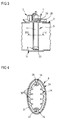
- FIG. 1 shows a sampling device 1 for an aqueous urea solution in a motor vehicle in partial section.
- the removal device 1 has a liquid container 2 for receiving the solution and a delivery unit 3 for promoting the solution to a connection piece 4. At the connecting piece 4 can be connected to a flow line, not shown, which leads to a device, also not shown is feasible for reducing nitrogen oxide emissions of an internal combustion engine.
- the removal device 1 has a second container 5 arranged in the liquid container 2.
- the liquid container 2 has a filler neck 6 with a ventilation device 7 shown schematically. This ventilation device 7 allows a limited pressure build-up in the liquid container 2.
- the second container 5 is connected via a check valve 8 to the liquid container 2.
- the check valve 8 allows only a flow of the solution from the liquid container 2 into the second container 5.
- the liquid container 2 has in its bottom 9 a sink 10 into which the check valve 8 having the end of the second container 5 is immersed.
- FIG. 2 shows in a sectional view through the removal device 1 FIG. 1 in that the delivery unit 3 has an air pump 11 with a check valve 12 leading to the second container 5 and an intake pipe 13 guided into the environment.
- the second container 5 has a storage chamber 14 for collecting the liquid and an injector chamber 15 guided to the connecting piece 4. Furthermore, the second container 5 has an oppressing chamber 16 guided up to the check valve 12 of the conveying unit 3.
- the pressurizing chamber 16 and the storage chamber 14 are over one in the upper, the check valve 12 of the conveyor unit 3 near the end arranged ventilation duct 17 connected to each other.
- a sensor channel 18 connects a pressure sensor 19 with the Bedrückungssch 16.
- the storage chamber 14, the Bedschreibammer 16 and the injector 15 are made as vertical pipe sections 20, 21, 22 and connected to each other via a foot part 23.
- the pipe sections 20 - 22 are made as a common profile piece 24 and fixed to a flange 25.
- FIG. 3 the profile piece 24 shown greatly simplified.
- the flange 25 carries the air pump 11 and seals a mounting opening 26 of the liquid container 2 from.
- the profile piece 24 is sealed by means of the foot part 23 with respect to the liquid container 2.
- a heating unit with two heating elements 27, 28 serves to heat the Bedschreibammer 16 and the injector chamber 15.
- the heating unit may also have a arranged on the outside of the profile piece 24 heating mat.
- FIG. 3 shows a sectional view through the removal device 1 from FIG. 2 along the line III - III.
- a switchable vent valve 29 is arranged on the flange 25, .
- the vent valve 29 selectively opens or blocks a connection of the liquid container 2 with the storage chamber 14 of the second container 5.
- FIG. 4 shows in a sectional view through the second container 5 FIG. 3 along the line IV - IV, the common, the Bed Wegungshunt 16, the storage chamber 14 and the injector 15 forming profile piece 24.
- the profile piece 24 is made of light metal by extrusion and has a plurality of heat-conducting, radially inwardly projecting ribs 30. On the outside of the profile piece 24, a sheath 31 is arranged for insulation.
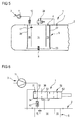
- FIG. 5 shows a circuit diagram of the removal device 1 from the FIGS. 1 to 4 .
- the air pump 11 is turned on and promotes air from the environment in the Bedschreibungshunt 16. About the ventilation duct 17, the air can flow into the storage chamber 14.
- existing solution is pressed by the air pressure in the injector 15 and thus promoted to the connecting piece 4.
- the switchable vent valve 29 separates in this promotion, the second container 5 of the liquid container 2. After the promotion of the solution, the liquid level in the storage chamber 14 and the Bedschreibungshunt 16 dropped.
- the air pump 11 For subsequent flow of liquid into the second container 5, the air pump 11 is turned off and the vent valve 29 is opened, whereby solution from the liquid container 2 can flow through the arranged in the bottom of the second container 5 check valve 8 in the second container 5.
- the ventilation device 7 air from the environment can flow into the liquid container 2 and replace the displaced solution.
- the heating elements 27, 28 in the injector chamber 15 and in the depression chamber 16 are energized and the liquid therein is thawed. Since the injector chamber 15 and the pressure chamber 16 have only a very small volume, the thawing process takes place in a particularly short time. Since ice is lighter than thawed liquid, moreover, the connection of the Bedgurungshunt 16 with the injector 15 in the foot part 23 of the second container 5 is also free of ice after a short time. By heat conduction, the liquid in the storage chamber 14 is thawed after some time, so that the entire, located in the second container 5 liquid can be conveyed to the connection piece 4.
- FIG. 6 shows a circuit diagram of another embodiment of the removal direction 1.
- a switchable filling valve 32 each to the air pump 11 and to the check valve 12 in the flange leading terminals 33, 34.
- the filling valve also has a guided to the liquid container 2 port 35, a led into the environment connection 36 and a guided into the storage chamber 14 port 37 for pressure equalization.
- the terminals 33, 34 of the air pump 11 and the check valve 12 are connected to each other and the other ports 35 - 37 are closed. This marks the too FIG. 5 described function of the removal device. 1
- a second switching position S2 of the filling valve 32 In a second switching position S2 of the filling valve 32, the terminals 33, 34 of the air pump 11 and the check valve 12 are separated from each other.
- the connection 33 of the air pump 11 is connected to the connection 35 leading to the liquid container 2.
- the port 37 of the storage chamber 14 is connected to the environmentally conductive port 36.
- the functions of the ventilation valve 29 are off FIG. 5 and the filling valve 32 FIG. 6 realized in a single valve.
Landscapes
- Engineering & Computer Science (AREA)
- Chemical & Material Sciences (AREA)
- Chemical Kinetics & Catalysis (AREA)
- Mechanical Engineering (AREA)
- Toxicology (AREA)
- Combustion & Propulsion (AREA)
- Health & Medical Sciences (AREA)
- General Engineering & Computer Science (AREA)
- Organic Low-Molecular-Weight Compounds And Preparation Thereof (AREA)
- Details Of Reciprocating Pumps (AREA)
- Jet Pumps And Other Pumps (AREA)
- Extraction Or Liquid Replacement (AREA)
- Exhaust Gas After Treatment (AREA)
- Loading And Unloading Of Fuel Tanks Or Ships (AREA)
Priority Applications (1)
| Application Number | Priority Date | Filing Date | Title |
|---|---|---|---|
| PL09179566T PL2199557T3 (pl) | 2008-12-17 | 2009-12-17 | Urządzenie do pobierania wodnego roztworu mocznika ze zbiornika w pojeździe mechanicznym |
Applications Claiming Priority (1)
| Application Number | Priority Date | Filing Date | Title |
|---|---|---|---|
| DE102008062673A DE102008062673A1 (de) | 2008-12-17 | 2008-12-17 | Entnahmeeinrichtung einer wässrigen Harnstoff-Lösung in einem Kraftfahrzeug |
Publications (2)
| Publication Number | Publication Date |
|---|---|
| EP2199557A1 EP2199557A1 (de) | 2010-06-23 |
| EP2199557B1 true EP2199557B1 (de) | 2012-02-29 |
Family
ID=41665078
Family Applications (1)
| Application Number | Title | Priority Date | Filing Date |
|---|---|---|---|
| EP09179566A Not-in-force EP2199557B1 (de) | 2008-12-17 | 2009-12-17 | Einrichtung zur Entnahme einer wässrigen Harnstoff-Lösung aus einem Tank in einem Kraftfahrzeug |
Country Status (6)
| Country | Link |
|---|---|
| EP (1) | EP2199557B1 (da) |
| AT (1) | ATE547596T1 (da) |
| DE (1) | DE102008062673A1 (da) |
| DK (1) | DK2199557T3 (da) |
| ES (1) | ES2383487T3 (da) |
| PL (1) | PL2199557T3 (da) |
Families Citing this family (5)
| Publication number | Priority date | Publication date | Assignee | Title |
|---|---|---|---|---|
| DE102009047637A1 (de) * | 2009-12-08 | 2011-06-09 | Robert Bosch Gmbh | Entlüftungselement für Vorratstank |
| DE102010005406A1 (de) * | 2010-01-22 | 2011-07-28 | Bayerische Motoren Werke Aktiengesellschaft, 80809 | Kraftfahrzeug mit einem Speicher-Behälter für Reduktionsmittel |
| DE102011108213A1 (de) * | 2011-07-21 | 2013-01-24 | Audi Ag | Beheizbarer Reduktionsmitteltank |
| US9267411B2 (en) * | 2013-08-15 | 2016-02-23 | Cummins Emission Solutions, Inc. | Pressurized tank vehicular fluid delivery system |
| DE102014206464B4 (de) * | 2014-04-03 | 2025-11-27 | Bayerische Motoren Werke Aktiengesellschaft | Reduktionsmittelbehälter eines Kraftfahrzeugs |
Family Cites Families (8)
| Publication number | Priority date | Publication date | Assignee | Title |
|---|---|---|---|---|
| DE19840404A1 (de) * | 1998-09-04 | 2000-03-09 | Siemens Ag | Verfahren zur katalytischen Entfernung von polyzyklischen aromatischen Nitro-, Nitroso- und/oder Amino-Verbindungen |
| GB2363084A (en) * | 2000-06-05 | 2001-12-12 | Ford Global Tech Inc | Exhaust gas purification system |
| DE10319841A1 (de) * | 2003-05-03 | 2004-12-02 | Hydraulik-Ring Gmbh | Einrichtung zur Abgasnachbehandlung in Dieselfahrzeugen |
| DE102005037201A1 (de) * | 2005-08-06 | 2007-02-22 | Eichenauer Heizelemente Gmbh & Co. Kg | Heizsystem |
| DE102006027487A1 (de) * | 2005-09-12 | 2007-03-15 | Robert Bosch Gmbh | Fahrzeugtank für ein flüssiges Reduktionsmittel, insbesondere für eine Harnstofflösung |
| DE102006046900A1 (de) * | 2006-10-04 | 2008-04-10 | Robert Bosch Gmbh | Verfahren zum Betrieb einer Verbrennungskraftmaschine |
| DE102006046899A1 (de) * | 2006-10-04 | 2008-04-10 | Robert Bosch Gmbh | Tank zur Bevorratung eines Reduktionsmittels |
| DE102007016858A1 (de) * | 2007-04-10 | 2008-10-16 | Robert Bosch Gmbh | SCR-Vorrichtung zur selektiven katalytischen Reduktion des Abgases einer Brennkraftmaschine |
-
2008
- 2008-12-17 DE DE102008062673A patent/DE102008062673A1/de not_active Ceased
-
2009
- 2009-12-17 AT AT09179566T patent/ATE547596T1/de active
- 2009-12-17 DK DK09179566.6T patent/DK2199557T3/da active
- 2009-12-17 EP EP09179566A patent/EP2199557B1/de not_active Not-in-force
- 2009-12-17 ES ES09179566T patent/ES2383487T3/es active Active
- 2009-12-17 PL PL09179566T patent/PL2199557T3/pl unknown
Also Published As
| Publication number | Publication date |
|---|---|
| ATE547596T1 (de) | 2012-03-15 |
| EP2199557A1 (de) | 2010-06-23 |
| DE102008062673A1 (de) | 2010-06-24 |
| DK2199557T3 (da) | 2012-05-21 |
| PL2199557T3 (pl) | 2012-08-31 |
| ES2383487T3 (es) | 2012-06-21 |
Similar Documents
| Publication | Publication Date | Title |
|---|---|---|
| EP2076660B1 (de) | Tank zur bevorratung eines reduktionsmittels | |
| EP2554813B1 (de) | Flüssigkeitsbehälter, insbesondere für eine wässrige Harnstofflösung | |
| EP2199557B1 (de) | Einrichtung zur Entnahme einer wässrigen Harnstoff-Lösung aus einem Tank in einem Kraftfahrzeug | |
| EP2791481B1 (de) | Dosieranordnung für ein flüssiges abgasnachbehandlungsmittel und dosierverfahren | |
| EP1841956A1 (de) | Abgasnachbehandlungsverfahren und vorrichtung hierzu | |
| DE102018201564B4 (de) | Vorrichtung zur Zuführung einer gefriergefährdeten Flüssigkeit in die Brennräume einer Brennkraftmaschine | |
| DE19750036C2 (de) | Kraftstoffördereinrichtung | |
| DE102013210742B4 (de) | Tankvorrichtung | |
| WO2010112396A1 (de) | Entnahmeeinrichtung für eine wässrige flüssigkeit in einem kraftfahrzeug | |
| DE102009014436B4 (de) | Fördereinrichtung zur Förderung einer wässrigen Flüssigkeit | |
| EP2126298A1 (de) | Vorrichtung zum dosieren eines reduktionsmittels | |
| EP2288795B1 (de) | Scr-system mit mehreren tanks | |
| EP3014099B1 (de) | Kraftstoff- fördersystem mit teildruckentlastungsventil an treibleitung einer saugstrahlpumpe | |
| DE102017219369A1 (de) | Verfahren zum Verhindern des Vereisens einer Einspritzanlage einer Brennkraftmaschine | |
| DE102008042954A1 (de) | Dosiersystem für ein flüssiges Medium, insbesondere Harnstoff-Wasser-Lösung | |
| DE10345225B4 (de) | Kraftstoffeinspritzsystem mit einer Entlüftungsvorrichtung | |
| DE102006048721B4 (de) | Katalytische Reduktionseinrichtung für eine katalytische Reduktion von Stickoxiden in Abgasanlagen | |
| DE102007033419A1 (de) | Trockensumpfschmiervorrichtung für eine Brennkraftmaschine | |
| DE102013211183A1 (de) | Entnahmeeinrichtung, Tankvorrichtung | |
| DE102012212892B4 (de) | Einspritzeinrichtung für eine Verbrennungskraftmaschine | |
| DE102018111474B4 (de) | Fluidsystem und Verwendung eines bidirektionalen Druckventils | |
| DE10026373A1 (de) | Hochdruck-Kraftstoffeinspritzanlage für eine Brennkraftmaschine | |
| DE102012015775A1 (de) | Nutzfahrzeugtankvorrichtung | |
| DE102006060838A1 (de) | Dosiersystem und Verfahren zum Betreiben eines Dosiersystems | |
| DE102012020396A1 (de) | Kraftstoffversorgungseinrichtung |
Legal Events
| Date | Code | Title | Description |
|---|---|---|---|
| PUAI | Public reference made under article 153(3) epc to a published international application that has entered the european phase |
Free format text: ORIGINAL CODE: 0009012 |
|
| AK | Designated contracting states |
Kind code of ref document: A1 Designated state(s): AT BE BG CH CY CZ DE DK EE ES FI FR GB GR HR HU IE IS IT LI LT LU LV MC MK MT NL NO PL PT RO SE SI SK SM TR |
|
| AX | Request for extension of the european patent |
Extension state: AL BA RS |
|
| 17P | Request for examination filed |
Effective date: 20101223 |
|
| 17Q | First examination report despatched |
Effective date: 20110211 |
|
| RIC1 | Information provided on ipc code assigned before grant |
Ipc: F01N 3/20 20060101AFI20110818BHEP |
|
| RTI1 | Title (correction) |
Free format text: DEVICE FOR EXTRACTING AN AQUEOUS UREA SOLUTION FROM A TANK IN A MOTOR VEHICLE |
|
| GRAP | Despatch of communication of intention to grant a patent |
Free format text: ORIGINAL CODE: EPIDOSNIGR1 |
|
| GRAS | Grant fee paid |
Free format text: ORIGINAL CODE: EPIDOSNIGR3 |
|
| GRAA | (expected) grant |
Free format text: ORIGINAL CODE: 0009210 |
|
| AK | Designated contracting states |
Kind code of ref document: B1 Designated state(s): AT BE BG CH CY CZ DE DK EE ES FI FR GB GR HR HU IE IS IT LI LT LU LV MC MK MT NL NO PL PT RO SE SI SK SM TR |
|
| REG | Reference to a national code |
Ref country code: GB Ref legal event code: FG4D Free format text: NOT ENGLISH Ref country code: CH Ref legal event code: EP |
|
| REG | Reference to a national code |
Ref country code: AT Ref legal event code: REF Ref document number: 547596 Country of ref document: AT Kind code of ref document: T Effective date: 20120315 |
|
| REG | Reference to a national code |
Ref country code: IE Ref legal event code: FG4D Free format text: LANGUAGE OF EP DOCUMENT: GERMAN |
|
| REG | Reference to a national code |
Ref country code: DE Ref legal event code: R096 Ref document number: 502009002899 Country of ref document: DE Effective date: 20120426 |
|
| REG | Reference to a national code |
Ref country code: DK Ref legal event code: T3 |
|
| REG | Reference to a national code |
Ref country code: ES Ref legal event code: FG2A Ref document number: 2383487 Country of ref document: ES Kind code of ref document: T3 Effective date: 20120621 |
|
| REG | Reference to a national code |
Ref country code: NL Ref legal event code: VDEP Effective date: 20120229 |
|
| LTIE | Lt: invalidation of european patent or patent extension |
Effective date: 20120229 |
|
| PG25 | Lapsed in a contracting state [announced via postgrant information from national office to epo] |
Ref country code: IS Free format text: LAPSE BECAUSE OF FAILURE TO SUBMIT A TRANSLATION OF THE DESCRIPTION OR TO PAY THE FEE WITHIN THE PRESCRIBED TIME-LIMIT Effective date: 20120629 Ref country code: NL Free format text: LAPSE BECAUSE OF FAILURE TO SUBMIT A TRANSLATION OF THE DESCRIPTION OR TO PAY THE FEE WITHIN THE PRESCRIBED TIME-LIMIT Effective date: 20120229 Ref country code: NO Free format text: LAPSE BECAUSE OF FAILURE TO SUBMIT A TRANSLATION OF THE DESCRIPTION OR TO PAY THE FEE WITHIN THE PRESCRIBED TIME-LIMIT Effective date: 20120529 Ref country code: LT Free format text: LAPSE BECAUSE OF FAILURE TO SUBMIT A TRANSLATION OF THE DESCRIPTION OR TO PAY THE FEE WITHIN THE PRESCRIBED TIME-LIMIT Effective date: 20120229 Ref country code: HR Free format text: LAPSE BECAUSE OF FAILURE TO SUBMIT A TRANSLATION OF THE DESCRIPTION OR TO PAY THE FEE WITHIN THE PRESCRIBED TIME-LIMIT Effective date: 20120229 |
|
| PG25 | Lapsed in a contracting state [announced via postgrant information from national office to epo] |
Ref country code: FI Free format text: LAPSE BECAUSE OF FAILURE TO SUBMIT A TRANSLATION OF THE DESCRIPTION OR TO PAY THE FEE WITHIN THE PRESCRIBED TIME-LIMIT Effective date: 20120229 Ref country code: GR Free format text: LAPSE BECAUSE OF FAILURE TO SUBMIT A TRANSLATION OF THE DESCRIPTION OR TO PAY THE FEE WITHIN THE PRESCRIBED TIME-LIMIT Effective date: 20120530 Ref country code: PT Free format text: LAPSE BECAUSE OF FAILURE TO SUBMIT A TRANSLATION OF THE DESCRIPTION OR TO PAY THE FEE WITHIN THE PRESCRIBED TIME-LIMIT Effective date: 20120629 Ref country code: LV Free format text: LAPSE BECAUSE OF FAILURE TO SUBMIT A TRANSLATION OF THE DESCRIPTION OR TO PAY THE FEE WITHIN THE PRESCRIBED TIME-LIMIT Effective date: 20120229 |
|
| REG | Reference to a national code |
Ref country code: PL Ref legal event code: T3 |
|
| REG | Reference to a national code |
Ref country code: IE Ref legal event code: FD4D |
|
| PG25 | Lapsed in a contracting state [announced via postgrant information from national office to epo] |
Ref country code: CY Free format text: LAPSE BECAUSE OF FAILURE TO SUBMIT A TRANSLATION OF THE DESCRIPTION OR TO PAY THE FEE WITHIN THE PRESCRIBED TIME-LIMIT Effective date: 20120229 |
|
| PG25 | Lapsed in a contracting state [announced via postgrant information from national office to epo] |
Ref country code: EE Free format text: LAPSE BECAUSE OF FAILURE TO SUBMIT A TRANSLATION OF THE DESCRIPTION OR TO PAY THE FEE WITHIN THE PRESCRIBED TIME-LIMIT Effective date: 20120229 Ref country code: CZ Free format text: LAPSE BECAUSE OF FAILURE TO SUBMIT A TRANSLATION OF THE DESCRIPTION OR TO PAY THE FEE WITHIN THE PRESCRIBED TIME-LIMIT Effective date: 20120229 Ref country code: SE Free format text: LAPSE BECAUSE OF FAILURE TO SUBMIT A TRANSLATION OF THE DESCRIPTION OR TO PAY THE FEE WITHIN THE PRESCRIBED TIME-LIMIT Effective date: 20120229 Ref country code: RO Free format text: LAPSE BECAUSE OF FAILURE TO SUBMIT A TRANSLATION OF THE DESCRIPTION OR TO PAY THE FEE WITHIN THE PRESCRIBED TIME-LIMIT Effective date: 20120229 Ref country code: SI Free format text: LAPSE BECAUSE OF FAILURE TO SUBMIT A TRANSLATION OF THE DESCRIPTION OR TO PAY THE FEE WITHIN THE PRESCRIBED TIME-LIMIT Effective date: 20120229 Ref country code: IE Free format text: LAPSE BECAUSE OF FAILURE TO SUBMIT A TRANSLATION OF THE DESCRIPTION OR TO PAY THE FEE WITHIN THE PRESCRIBED TIME-LIMIT Effective date: 20120229 |
|
| PG25 | Lapsed in a contracting state [announced via postgrant information from national office to epo] |
Ref country code: SK Free format text: LAPSE BECAUSE OF FAILURE TO SUBMIT A TRANSLATION OF THE DESCRIPTION OR TO PAY THE FEE WITHIN THE PRESCRIBED TIME-LIMIT Effective date: 20120229 |
|
| PLBE | No opposition filed within time limit |
Free format text: ORIGINAL CODE: 0009261 |
|
| STAA | Information on the status of an ep patent application or granted ep patent |
Free format text: STATUS: NO OPPOSITION FILED WITHIN TIME LIMIT |
|
| 26N | No opposition filed |
Effective date: 20121130 |
|
| REG | Reference to a national code |
Ref country code: DE Ref legal event code: R097 Ref document number: 502009002899 Country of ref document: DE Effective date: 20121130 |
|
| BERE | Be: lapsed |
Owner name: CONTINENTAL AUTOMOTIVE G.M.B.H. Effective date: 20121231 |
|
| PG25 | Lapsed in a contracting state [announced via postgrant information from national office to epo] |
Ref country code: MC Free format text: LAPSE BECAUSE OF NON-PAYMENT OF DUE FEES Effective date: 20121231 Ref country code: BG Free format text: LAPSE BECAUSE OF FAILURE TO SUBMIT A TRANSLATION OF THE DESCRIPTION OR TO PAY THE FEE WITHIN THE PRESCRIBED TIME-LIMIT Effective date: 20120529 |
|
| PG25 | Lapsed in a contracting state [announced via postgrant information from national office to epo] |
Ref country code: BE Free format text: LAPSE BECAUSE OF NON-PAYMENT OF DUE FEES Effective date: 20121231 |
|
| PG25 | Lapsed in a contracting state [announced via postgrant information from national office to epo] |
Ref country code: MT Free format text: LAPSE BECAUSE OF FAILURE TO SUBMIT A TRANSLATION OF THE DESCRIPTION OR TO PAY THE FEE WITHIN THE PRESCRIBED TIME-LIMIT Effective date: 20120229 |
|
| PG25 | Lapsed in a contracting state [announced via postgrant information from national office to epo] |
Ref country code: TR Free format text: LAPSE BECAUSE OF FAILURE TO SUBMIT A TRANSLATION OF THE DESCRIPTION OR TO PAY THE FEE WITHIN THE PRESCRIBED TIME-LIMIT Effective date: 20120229 |
|
| REG | Reference to a national code |
Ref country code: DE Ref legal event code: R081 Ref document number: 502009002899 Country of ref document: DE Owner name: EMITEC GESELLSCHAFT FUER EMISSIONSTECHNOLOGIE , DE Free format text: FORMER OWNER: CONTINENTAL AUTOMOTIVE GMBH, 30165 HANNOVER, DE Effective date: 20140416 Ref country code: DE Ref legal event code: R081 Ref document number: 502009002899 Country of ref document: DE Owner name: CONTINENTAL AUTOMOTIVE GMBH, DE Free format text: FORMER OWNER: CONTINENTAL AUTOMOTIVE GMBH, 30165 HANNOVER, DE Effective date: 20140416 |
|
| PG25 | Lapsed in a contracting state [announced via postgrant information from national office to epo] |
Ref country code: SM Free format text: LAPSE BECAUSE OF FAILURE TO SUBMIT A TRANSLATION OF THE DESCRIPTION OR TO PAY THE FEE WITHIN THE PRESCRIBED TIME-LIMIT Effective date: 20120229 Ref country code: LU Free format text: LAPSE BECAUSE OF NON-PAYMENT OF DUE FEES Effective date: 20121217 |
|
| REG | Reference to a national code |
Ref country code: GB Ref legal event code: 732E Free format text: REGISTERED BETWEEN 20140605 AND 20140611 |
|
| PG25 | Lapsed in a contracting state [announced via postgrant information from national office to epo] |
Ref country code: HU Free format text: LAPSE BECAUSE OF FAILURE TO SUBMIT A TRANSLATION OF THE DESCRIPTION OR TO PAY THE FEE WITHIN THE PRESCRIBED TIME-LIMIT Effective date: 20091217 |
|
| REG | Reference to a national code |
Ref country code: CH Ref legal event code: PL |
|
| REG | Reference to a national code |
Ref country code: FR Ref legal event code: TP Owner name: EITEC, DE Effective date: 20140715 |
|
| PG25 | Lapsed in a contracting state [announced via postgrant information from national office to epo] |
Ref country code: LI Free format text: LAPSE BECAUSE OF NON-PAYMENT OF DUE FEES Effective date: 20131231 Ref country code: CH Free format text: LAPSE BECAUSE OF NON-PAYMENT OF DUE FEES Effective date: 20131231 |
|
| PG25 | Lapsed in a contracting state [announced via postgrant information from national office to epo] |
Ref country code: MK Free format text: LAPSE BECAUSE OF FAILURE TO SUBMIT A TRANSLATION OF THE DESCRIPTION OR TO PAY THE FEE WITHIN THE PRESCRIBED TIME-LIMIT Effective date: 20120229 |
|
| REG | Reference to a national code |
Ref country code: FR Ref legal event code: PLFP Year of fee payment: 7 |
|
| PGFP | Annual fee paid to national office [announced via postgrant information from national office to epo] |
Ref country code: DK Payment date: 20151221 Year of fee payment: 7 Ref country code: GB Payment date: 20151221 Year of fee payment: 7 |
|
| REG | Reference to a national code |
Ref country code: AT Ref legal event code: MM01 Ref document number: 547596 Country of ref document: AT Kind code of ref document: T Effective date: 20141217 |
|
| REG | Reference to a national code |
Ref country code: DE Ref legal event code: R082 Ref document number: 502009002899 Country of ref document: DE Ref country code: DE Ref legal event code: R081 Ref document number: 502009002899 Country of ref document: DE Owner name: CONTINENTAL AUTOMOTIVE GMBH, DE Free format text: FORMER OWNER: EMITEC GESELLSCHAFT FUER EMISSIONSTECHNOLOGIE MBH, 53797 LOHMAR, DE |
|
| REG | Reference to a national code |
Ref country code: DE Ref legal event code: R082 Ref document number: 502009002899 Country of ref document: DE Ref country code: DE Ref legal event code: R081 Ref document number: 502009002899 Country of ref document: DE Owner name: CONTINENTAL AUTOMOTIVE GMBH, DE Free format text: FORMER OWNER: CONTINENTAL AUTOMOTIVE GMBH, 30165 HANNOVER, DE |
|
| PGFP | Annual fee paid to national office [announced via postgrant information from national office to epo] |
Ref country code: ES Payment date: 20151214 Year of fee payment: 7 Ref country code: FR Payment date: 20151221 Year of fee payment: 7 |
|
| REG | Reference to a national code |
Ref country code: GB Ref legal event code: 732E Free format text: REGISTERED BETWEEN 20160331 AND 20160406 |
|
| PGFP | Annual fee paid to national office [announced via postgrant information from national office to epo] |
Ref country code: DE Payment date: 20151231 Year of fee payment: 7 |
|
| PG25 | Lapsed in a contracting state [announced via postgrant information from national office to epo] |
Ref country code: AT Free format text: LAPSE BECAUSE OF NON-PAYMENT OF DUE FEES Effective date: 20141217 |
|
| PGFP | Annual fee paid to national office [announced via postgrant information from national office to epo] |
Ref country code: PL Payment date: 20161123 Year of fee payment: 8 |
|
| PGFP | Annual fee paid to national office [announced via postgrant information from national office to epo] |
Ref country code: IT Payment date: 20161223 Year of fee payment: 8 |
|
| REG | Reference to a national code |
Ref country code: DE Ref legal event code: R119 Ref document number: 502009002899 Country of ref document: DE |
|
| REG | Reference to a national code |
Ref country code: DK Ref legal event code: EBP Effective date: 20161231 |
|
| GBPC | Gb: european patent ceased through non-payment of renewal fee |
Effective date: 20161217 |
|
| REG | Reference to a national code |
Ref country code: FR Ref legal event code: ST Effective date: 20170831 |
|
| PG25 | Lapsed in a contracting state [announced via postgrant information from national office to epo] |
Ref country code: FR Free format text: LAPSE BECAUSE OF NON-PAYMENT OF DUE FEES Effective date: 20170102 |
|
| PG25 | Lapsed in a contracting state [announced via postgrant information from national office to epo] |
Ref country code: DE Free format text: LAPSE BECAUSE OF NON-PAYMENT OF DUE FEES Effective date: 20170701 Ref country code: GB Free format text: LAPSE BECAUSE OF NON-PAYMENT OF DUE FEES Effective date: 20161217 |
|
| PG25 | Lapsed in a contracting state [announced via postgrant information from national office to epo] |
Ref country code: DK Free format text: LAPSE BECAUSE OF NON-PAYMENT OF DUE FEES Effective date: 20161231 |
|
| PG25 | Lapsed in a contracting state [announced via postgrant information from national office to epo] |
Ref country code: ES Free format text: LAPSE BECAUSE OF NON-PAYMENT OF DUE FEES Effective date: 20161218 |
|
| PG25 | Lapsed in a contracting state [announced via postgrant information from national office to epo] |
Ref country code: IT Free format text: LAPSE BECAUSE OF NON-PAYMENT OF DUE FEES Effective date: 20171217 |
|
| REG | Reference to a national code |
Ref country code: ES Ref legal event code: FD2A Effective date: 20181113 |
|
| PG25 | Lapsed in a contracting state [announced via postgrant information from national office to epo] |
Ref country code: PL Free format text: LAPSE BECAUSE OF NON-PAYMENT OF DUE FEES Effective date: 20171217 |