EP2199532A2 - Drilling tool for stone - Google Patents
Drilling tool for stone Download PDFInfo
- Publication number
- EP2199532A2 EP2199532A2 EP09176741A EP09176741A EP2199532A2 EP 2199532 A2 EP2199532 A2 EP 2199532A2 EP 09176741 A EP09176741 A EP 09176741A EP 09176741 A EP09176741 A EP 09176741A EP 2199532 A2 EP2199532 A2 EP 2199532A2
- Authority
- EP
- European Patent Office
- Prior art keywords
- drilling tool
- rotary driving
- drill head
- tool according
- locking means
- Prior art date
- Legal status (The legal status is an assumption and is not a legal conclusion. Google has not performed a legal analysis and makes no representation as to the accuracy of the status listed.)
- Withdrawn
Links
- 238000005553 drilling Methods 0.000 title claims description 26
- 239000004575 stone Substances 0.000 title 1
- 230000008878 coupling Effects 0.000 claims abstract description 9
- 238000010168 coupling process Methods 0.000 claims abstract description 9
- 238000005859 coupling reaction Methods 0.000 claims abstract description 9
- 239000011435 rock Substances 0.000 claims description 4
- 230000037431 insertion Effects 0.000 description 3
- 238000003780 insertion Methods 0.000 description 3
- 238000004519 manufacturing process Methods 0.000 description 3
- 238000011010 flushing procedure Methods 0.000 description 2
- 238000005516 engineering process Methods 0.000 description 1
- 239000000463 material Substances 0.000 description 1
- 239000002184 metal Substances 0.000 description 1
- 230000002093 peripheral effect Effects 0.000 description 1
Images

Classifications
-
- E—FIXED CONSTRUCTIONS
- E21—EARTH DRILLING; MINING
- E21B—EARTH DRILLING, e.g. DEEP DRILLING; OBTAINING OIL, GAS, WATER, SOLUBLE OR MELTABLE MATERIALS OR A SLURRY OF MINERALS FROM WELLS
- E21B17/00—Drilling rods or pipes; Flexible drill strings; Kellies; Drill collars; Sucker rods; Cables; Casings; Tubings
- E21B17/02—Couplings; joints
- E21B17/04—Couplings; joints between rod or the like and bit or between rod and rod or the like
- E21B17/046—Couplings; joints between rod or the like and bit or between rod and rod or the like with ribs, pins, or jaws, and complementary grooves or the like, e.g. bayonet catches
-
- B—PERFORMING OPERATIONS; TRANSPORTING
- B23—MACHINE TOOLS; METAL-WORKING NOT OTHERWISE PROVIDED FOR
- B23B—TURNING; BORING
- B23B51/00—Tools for drilling machines
-
- B—PERFORMING OPERATIONS; TRANSPORTING
- B28—WORKING CEMENT, CLAY, OR STONE
- B28D—WORKING STONE OR STONE-LIKE MATERIALS
- B28D1/00—Working stone or stone-like materials, e.g. brick, concrete or glass, not provided for elsewhere; Machines, devices, tools therefor
- B28D1/14—Working stone or stone-like materials, e.g. brick, concrete or glass, not provided for elsewhere; Machines, devices, tools therefor by boring or drilling
- B28D1/146—Tools therefor
-
- E—FIXED CONSTRUCTIONS
- E21—EARTH DRILLING; MINING
- E21B—EARTH DRILLING, e.g. DEEP DRILLING; OBTAINING OIL, GAS, WATER, SOLUBLE OR MELTABLE MATERIALS OR A SLURRY OF MINERALS FROM WELLS
- E21B19/00—Handling rods, casings, tubes or the like outside the borehole, e.g. in the derrick; Apparatus for feeding the rods or cables
- E21B19/18—Connecting or disconnecting drill bit and drilling pipe
-
- B—PERFORMING OPERATIONS; TRANSPORTING
- B23—MACHINE TOOLS; METAL-WORKING NOT OTHERWISE PROVIDED FOR
- B23B—TURNING; BORING
- B23B2226/00—Materials of tools or workpieces not comprising a metal
- B23B2226/75—Stone, rock or concrete
-
- B—PERFORMING OPERATIONS; TRANSPORTING
- B23—MACHINE TOOLS; METAL-WORKING NOT OTHERWISE PROVIDED FOR
- B23B—TURNING; BORING
- B23B2251/00—Details of tools for drilling machines
- B23B2251/02—Connections between shanks and removable cutting heads
Definitions
- the present invention relates to a drilling tool for rock referred to in the preamble of claim 1. Art.
- Such drilling tools for rock have an at least partially hollow boring bar with a flushing channel, a drive-side insertion for receiving in the tool holder of a driving Bohrtechniks and a driven-side coupling means and a rotationally fixed thereto and releasably connected by means of a locking means drill head with flushing openings and cutting hard material.
- a drilling tool for rock with an at least partially rotating and hitting claimed drill rod and a carbide occupied with hard drill head The drill rod and the drill head are rotatably limited by a coupling means axially movable and detachably connected to one another via a locking means, wherein at least one radially projecting rotational support web is arranged at one end face of the drill rod.
- the rotary driving web engages in at least one along the tool axis extending rotational drive slot of a rotary drive surface of a cup-shaped drill head.
- Object of the present invention is to further improve the known drilling tool and in particular to simplify the assembly and disassembly of drill head to the drill rod.
- the coupling means has elastic locking means for holding the rotary driving land in the rotary driving slot.
- the elastic locking means are arranged on the boring bar, whereby additional costs in the production of the drill heads are avoided and any additional costs for the boring bar due to the longer service life of the boring bar only slightly affect the overall cost.
- the elastic locking means may also be arranged on the drill head, whereby the noise emission of the drilling tool is reduced.
- this variant is particularly advantageous for smaller drill diameters.
- the elastic locking means comprise a spring element disposed on the rotary driving web, which is resiliently movable in a circumferential direction of the boring bar.
- the elastic locking means comprise a spring element arranged on the drill head which is resiliently movable in a circumferential direction of the drill head.
- the elastic locking means comprise at least one elastic wall portion of the drill head.
- the width of the rotary driving slot in the region of the opening is smaller than the largest width of the rotary driving web.
- the elastic deformability of the drill head or its peripheral wall is advantageously utilized.
- a narrowing of the rotary driving slot is achieved in that a projection which tapers the opening is arranged on the wall section in the region of the axial opening of the rotary driving slot.
- a further slot is arranged in the wall section in a region lying behind the projection in a working direction of rotation. As a result, the elastic expansion of the opening or the narrowed point during insertion and withdrawal of the rotary driving web is facilitated from the rotary driving slot.
- the rotary driving slot in the region of its opening at least one chamfer, whereby the widening of the opening or the bottleneck of the rotary driving slot is facilitated by the rotary driving web.
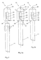
- FIGS. 1a to 1c is a first inventive drilling tool 10, which extends along a tool axis A reproduced.
- This drilling tool 10 has a drill head 21, which carries a cutting body 29 made of hard metal, and an elongated boring bar 11.
- the drill head 21 and the boring bar 11 are provided with coupling means which have four rotational engagement slots 22 running along the tool axis A at the drill head 21 and four rotational support webs 12 arranged at a front end of the drill rod 11.
- a course of the rotational engagement slots 22 at an angle of up to 25 ° relative to the tool axis A is also understood as extending along or along a tool axis.
- the Drehit Vietnamesestege 12 can be inserted via axial openings 28 of the rotary drive slots 22 in each case in the associated rotational drive slots 22 to releasably but rotatably set the drill head 21 on the drill rod 11.
- the openings 28 have as Einöffleicht ceremonies for the rotary driving webs 12 each at least one side of the openings 28 a chamfer 27.
- the rotary driving webs 12 are preferably tapered at its end facing the drill head 21 in order to facilitate insertion into the rotary driving slots.
- rotational engagement slots 22 each have a locking lug 30 in the rotational drive slots 22 and prevented in the manner of a bayonet locking an extension of the rotary driving webs 12 during the drilling operation.
- At least one of the rotary driving webs 21 is on the side opposite to the direction of rotation R, still designed as a spring bridge spring element 13 is arranged, which acts as an elastic locking means and on the drill head 21 when he as out Fig. 1c can be seen attached to the drill rod 21, against the working direction of rotation R is acted upon elastically.
- the Drehit Cyprusstege 12 are thereby held in the on the locking lugs 30 partially axially closed areas of the rotary drive slots 22.
- the spring element 13 is at least limited resiliently movable in a circumferential direction of the drill rod 11.
- the drill head 21 is held securely and captively on the drill rod 11 via the coupling means in combination with the elastic locking means.
- FIGS. 2a to 2c shown drilling tool 10 differs from that in the FIGS. 1a to 1c illustrated drilling tool, that instead of the spring element 13 on the rotary driving web 21 there is arranged a spring element 23 designed as a spring tongue elastic locking means in at least one of the rotary drive slots 12 which is resiliently movable in a circumferential direction of the drill head 21.
- the function of the spring element 23 corresponds to the previous to the FIGS. 1a to 1c For this reason, and because of reference numerals not mentioned here, reference is made in its entirety to the description of FIGS FIGS. 1a to 1 c.
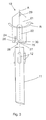
- FIG. 3 shown drilling tool 10 differs from that in the FIGS. 1a to 1c illustrated drilling tool that the elastic locking means there instead of the spring element 13 on the rotary driving web 21 at least one elastic wall portion 24 of the drill head 21 and at least one projecting from the wall portion 24 and the rotational driving slot 22 in the region of its axial opening 28 tapered projection 25 include. Further, in addition to the wall portion 24 in a working direction of rotation R behind the projection 25 area another slot 26 is arranged, which increases the elastic mobility of the wall portion 24.
- the projection 25 in this case has the chamfer 27 in the form of a curved outer contour, which facilitates the widening of the opening 28 of the rotary driving slot 22 by the rotary driving web 12.
- the function of the elastic wall section 24 corresponds to the function of the previous to the FIGS. 1a to 2c described spring elements 13, 23, why reference is made in this respect and because not mentioned here reference numerals to the description of the FIGS. 1a to 2c ,
Abstract
Description
Die vorliegende Erfindung betrifft ein Bohrwerkzeug für Gestein der im Oberbegriff von Patentanspruch 1 genannten Art.The present invention relates to a drilling tool for rock referred to in the preamble of claim 1. Art.
Derartige Bohrwerkzeuge für Gestein weisen eine zumindest teilweise hohle Bohrstange mit einem Spülkanal, einem antriebsseitigen Einsteckende zur Aufnahme in die Werkzeugaufnahme eines antreibenden Bohrwerkzeuggerätes und einem abtriebsseitigen Kupplungsmittel sowie ein mit diesem drehfest und mittels eines Arretierungsmittels lösbar verbundenen Bohrkopf mit Spülöffnungen und Schneiden aus Hartstoff auf.Such drilling tools for rock have an at least partially hollow boring bar with a flushing channel, a drive-side insertion for receiving in the tool holder of a driving Bohrwerkzeuggerätes and a driven-side coupling means and a rotationally fixed thereto and releasably connected by means of a locking means drill head with flushing openings and cutting hard material.
Aus der
Aufgabe der vorliegenden Erfindung ist es, das bekannte Bohrwerkzeug weiter zu verbessern und insbesondere die Montage und Demontage von Bohrkopf an die Bohrstange zu vereinfachen.Object of the present invention is to further improve the known drilling tool and in particular to simplify the assembly and disassembly of drill head to the drill rod.
Die Aufgabe wird durch ein Bohrwerkzeug mit den in Patentanspruch 1 genannten Merkmalen gelöst. Demnach weisen die Kupplungsmittel elastische Verriegelungsmittel zum Halten des Drehmitnahmestegs in dem Drehmitnahmeschlitz auf. Hierdurch wird auf technische einfache Weise eine zuverlässige Verbindung von Bohrkopf und Bohrstange erreicht, insbesondere können Bohrkopf und Bohrstange ohne Hilfsmittel von Hand wieder getrennt werden. Ausserdem ist die erfindungsgemässe Lösung sehr kostengünstig zu fertigen.The object is achieved by a drilling tool with the features mentioned in claim 1. Accordingly, the coupling means has elastic locking means for holding the rotary driving land in the rotary driving slot. As a result, a reliable connection of drill head and drill rod is achieved in a simple technical way, in particular drill head and boring bar without tools by hand again be separated. In addition, the inventive solution is very inexpensive to manufacture.
Vorteilhaft sind die elastischen Verriegelungsmittel an der Bohrstange angeordnet, wodurch Mehrkosten bei der Fertigung der Bohrköpfe vermieden werden und sich die ggf. auftretenden Mehrkosten für die Bohrstange aufgrund der längeren Nutzungsdauer der Bohrstange nur geringfügig auf die Gesamtkosten niederschlagen.Advantageously, the elastic locking means are arranged on the boring bar, whereby additional costs in the production of the drill heads are avoided and any additional costs for the boring bar due to the longer service life of the boring bar only slightly affect the overall cost.
Alternativ können die elastischen Verriegelungsmittel auch am Bohrkopf angeordnet sein, wodurch die Geräuschabstrahlung des Bohrwerkzeugs reduziert wird. Fertigungstechnisch vorteilhaft ist diese Variante insbesondere bei kleineren Bohrerdurchmessern.Alternatively, the elastic locking means may also be arranged on the drill head, whereby the noise emission of the drilling tool is reduced. In terms of manufacturing technology, this variant is particularly advantageous for smaller drill diameters.
In einer konstruktiv einfachen Lösung beinhalten die elastischen Verriegelungsmittel ein am Drehmitnahmesteg angeordnetes Federelement, das in einer Umfangsrichtung der Bohrstange federelastisch beweglich ist.In a structurally simple solution, the elastic locking means comprise a spring element disposed on the rotary driving web, which is resiliently movable in a circumferential direction of the boring bar.
In einer weiteren konstruktiv einfachen Lösung beinhalten die elastischen Verriegelungsmittel ein am Bohrkopf angeordnetes Federelement, das in einer Umfangsrichtung des Bohrkopfs federelastisch beweglich ist.In a further structurally simple solution, the elastic locking means comprise a spring element arranged on the drill head which is resiliently movable in a circumferential direction of the drill head.
In einer besonders kostengünstig umsetzbaren Lösung beinhalten die elastischen Verriegelungsmittel wenigstens einen elastischen Wandabschnitt des Bohrkopfs. Gleichzeitig ist die Weite des Drehmitnahmeschlitzes im Bereich der Öffnung kleiner ist als die grösste Breite des Drehmitnahmestegs. Hierbei wird auf vorteilhafte Weise die elastische Verformbarkeit des Bohrkopf bzw. dessen Umfangswand ausgenutzt.In a particularly cost-effective solution, the elastic locking means comprise at least one elastic wall portion of the drill head. At the same time, the width of the rotary driving slot in the region of the opening is smaller than the largest width of the rotary driving web. Here, the elastic deformability of the drill head or its peripheral wall is advantageously utilized.
Vorteilhaft wird eine Verengung des Drehmitnahmeschlitzes dadurch erreicht, dass an dem Wandabschnitt im Bereich der axialen Öffnung des Drehmitnahmeschlitzes ein die Öffnung verjüngender Vorsprung angeordnet ist.Advantageously, a narrowing of the rotary driving slot is achieved in that a projection which tapers the opening is arranged on the wall section in the region of the axial opening of the rotary driving slot.
Dabei kann es günstig sein, wenn in dem Wandabschnitt in einem in einer Arbeitsdrehrichtung hinter dem Vorsprung liegenden Bereich ein weiterer Schlitz angeordnet ist. Hierdurch wird die elastische Aufweitung der Öffnung bzw. der verengten Stelle beim Einführen und Rausziehen des Drehmitnahmestegs aus dem Drehmitnahmeschlitz erleichtert.It may be advantageous if a further slot is arranged in the wall section in a region lying behind the projection in a working direction of rotation. As a result, the elastic expansion of the opening or the narrowed point during insertion and withdrawal of the rotary driving web is facilitated from the rotary driving slot.
Vorteilhaft weist der Drehmitnahmeschlitz im Bereich seiner Öffnung wenigstens eine Anschrägung auf, wodurch das Aufweiten der Öffnung bzw. der Engstelle des Drehmitnahmeschlitzes durch den Drehmitnahmesteg erleichtert wird.Advantageously, the rotary driving slot in the region of its opening at least one chamfer, whereby the widening of the opening or the bottleneck of the rotary driving slot is facilitated by the rotary driving web.
In den Zeichnungen ist die Erfindung in einem Ausführungsbeispiel dargestellt.In the drawings, the invention is shown in one embodiment.
Es zeigen:
- Fig. 1a bis 1c
- ein erfindungsgemässes Bohrwerkzeug in Seitenansicht in drei verschiedenen Montagestadien,
- Fig. 2a bis 2c
- ein weiteres Bohrwerkzeug in Seitenansicht in drei verschiedenen Montagestadien,
- Fig. 3
- ein weiteres Bohrwerkzeug in Seitenansicht, bei dem der Bohrkopf noch nicht auf der Bohrstange montiert ist.
- Fig. 1a to 1c
- an inventive drilling tool in side view in three different assembly stages,
- Fig. 2a to 2c
- another drilling tool in side view in three different assembly stages,
- Fig. 3
- another drilling tool in side view, in which the drill head is not yet mounted on the drill rod.
In den
An wenigstens einem der Drehmitnahmestege 21 ist an der Seite, die entgegengesetzt zur Arbeitsdrehrichtung R liegt, noch ein als Federbrücke ausgebildetes Federelement 13 angeordnet, das als elastische Verriegelungsmittel fungiert und über das der Bohrkopf 21, wenn er wie aus
Das in den
Das in
Die Funktion des elastischen Wandabschnitt 24 entspricht dabei der Funktion der vorhergehend zu den
Claims (9)
dadurch gekennzeichnet,
dass die Kupplungsmittel elastische Verriegelungsmittel zum Halten des Drehmitnahmestegs (12) in dem Drehmitnahmeschlitz (22) aufweisen.Drilling tool for rock, comprising a boring bar (11) and a pot-shaped boring head (21), wherein the boring head (21) and the boring bar (11) are provided with coupling means which comprise at least one rotary driving slot (22) of the boring head along the tool axis (A) (21) and at least one arranged at one end of the boring bar (11) and in the rotary driving slot (22) insertable rotary driving web (12), releasably but rotatably connected,
characterized,
in that the coupling means comprise elastic locking means for holding the rotary driving web (12) in the rotary driving slot (22).
Applications Claiming Priority (1)
| Application Number | Priority Date | Filing Date | Title |
|---|---|---|---|
| DE102008054925A DE102008054925B4 (en) | 2008-12-18 | 2008-12-18 | Drilling tool for rock |
Publications (2)
| Publication Number | Publication Date |
|---|---|
| EP2199532A2 true EP2199532A2 (en) | 2010-06-23 |
| EP2199532A3 EP2199532A3 (en) | 2016-03-09 |
Family
ID=42027888
Family Applications (1)
| Application Number | Title | Priority Date | Filing Date |
|---|---|---|---|
| EP09176741.8A Withdrawn EP2199532A3 (en) | 2008-12-18 | 2009-11-23 | Drilling tool for stone |
Country Status (5)
| Country | Link |
|---|---|
| US (1) | US20100155144A1 (en) |
| EP (1) | EP2199532A3 (en) |
| JP (1) | JP2010142946A (en) |
| CN (1) | CN101745988A (en) |
| DE (1) | DE102008054925B4 (en) |
Families Citing this family (5)
| Publication number | Priority date | Publication date | Assignee | Title |
|---|---|---|---|---|
| US9028180B2 (en) | 2012-04-04 | 2015-05-12 | Iscar, Ltd. | Cutting tool and cutting head with a resilient coupling portion |
| JP5983084B2 (en) * | 2012-06-24 | 2016-08-31 | 日立工機株式会社 | Nailer |
| US8882413B2 (en) | 2012-11-26 | 2014-11-11 | Iscar, Ltd. | Cutting tool and cutting insert with a rearward resilience slit |
| CN106555554B (en) * | 2016-11-24 | 2018-07-03 | 宜昌市燕狮科技开发有限责任公司 | A kind of bolt-type drill pipe connecting sleeve with wind spring |
| CN111894565B (en) * | 2020-07-14 | 2024-03-22 | 中煤科工开采研究院有限公司 | Device for testing crack expansion in surrounding rock |
Citations (1)
| Publication number | Priority date | Publication date | Assignee | Title |
|---|---|---|---|---|
| EP1267033A1 (en) | 2001-06-15 | 2002-12-18 | HILTI Aktiengesellschaft | Rock drilling tool |
Family Cites Families (11)
| Publication number | Priority date | Publication date | Assignee | Title |
|---|---|---|---|---|
| US611305A (en) * | 1898-09-27 | Pipe-lock | ||
| US1526565A (en) * | 1923-06-16 | 1925-02-17 | William C Siderfin | Mining bit |
| GB690531A (en) * | 1950-06-28 | 1953-04-22 | Sandvikens Jernverks Ab | Drill rod assembly for rock drilling operations |
| US3575446A (en) * | 1969-02-28 | 1971-04-20 | Don W Brantley | Quick-connect coupler |
| DE3533929A1 (en) * | 1985-05-07 | 1986-11-13 | Geißler & Kuper GmbH Diamantwerkzeug - Wiederaufbereitung, 3100 Celle | Diamond bit with shank tube and threaded tube connection |
| FR2694053B1 (en) * | 1992-07-24 | 1994-09-02 | Souriau & Cie | Bayonet type locking connection assembly. |
| DE59509847D1 (en) * | 1994-08-01 | 2001-12-20 | Ham Final Brno | FINISHING TOOL FOR PRECISION HOLES |
| US5741084A (en) * | 1995-03-27 | 1998-04-21 | Del Rio; Eddy H. | Wear compensating axial connection |
| GB2324486B (en) * | 1997-04-24 | 2001-06-20 | Marcrist Ind Ltd | Masonry core-cutting tool |
| EP0909870A1 (en) * | 1997-10-15 | 1999-04-21 | DIAMANT BOART Société Anonyme | Coupling for a force transmitting device |
| DE20119532U1 (en) * | 2001-12-01 | 2002-02-28 | Englert Thomas | clutch |
-
2008
- 2008-12-18 DE DE102008054925A patent/DE102008054925B4/en not_active Expired - Fee Related
-
2009
- 2009-11-23 EP EP09176741.8A patent/EP2199532A3/en not_active Withdrawn
- 2009-12-15 JP JP2009284388A patent/JP2010142946A/en active Pending
- 2009-12-17 CN CN200910253749A patent/CN101745988A/en active Pending
- 2009-12-17 US US12/640,580 patent/US20100155144A1/en not_active Abandoned
Patent Citations (1)
| Publication number | Priority date | Publication date | Assignee | Title |
|---|---|---|---|---|
| EP1267033A1 (en) | 2001-06-15 | 2002-12-18 | HILTI Aktiengesellschaft | Rock drilling tool |
Also Published As
| Publication number | Publication date |
|---|---|
| US20100155144A1 (en) | 2010-06-24 |
| CN101745988A (en) | 2010-06-23 |
| DE102008054925B4 (en) | 2010-09-09 |
| DE102008054925A1 (en) | 2010-07-01 |
| JP2010142946A (en) | 2010-07-01 |
| EP2199532A3 (en) | 2016-03-09 |
Similar Documents
| Publication | Publication Date | Title |
|---|---|---|
| DE2945766C2 (en) | Drill bit and drill tool with such a drill bit | |
| DE202012100353U1 (en) | Tool holder for mounting a chisel tool | |
| DE102011079115A1 (en) | Rotatable tool for use in e.g. cutting machine utilized for removing hard concrete surface for road construction in e.g. civil engineering, has spring washer provided at cylindrical shaft behind annular flange | |
| EP2213419A1 (en) | Hand-held power tool with tensioning device for a tool | |
| DE202006013890U1 (en) | Tool for cutting processes comprises a working plate having a fixing region with a fixing opening for fixing to a driveshaft of a drive, especially an oscillating drive | |
| EP1574309A1 (en) | Chisel for a mill | |
| DE102012222617A1 (en) | Shaft for rotational coupling of a main device with a tubular device | |
| DE102007039367A1 (en) | Tool for cutting processes comprises a working plate having a fixing region with a fixing opening for fixing to a driveshaft of a drive, especially an oscillating drive | |
| DE102005001535B3 (en) | Mounting for mining cutter has security ring with face engaging flat face on cutter shaft | |
| EP2199532A2 (en) | Drilling tool for stone | |
| EP3140511B1 (en) | Shank chisel and fixing assembly for a shank chisel | |
| EP0732164A1 (en) | Drilling tool, particularly for percusive drilling of stone | |
| CH615726A5 (en) | ||
| EP1447195A1 (en) | Drilling device with a core drill | |
| DE3233980C1 (en) | Direct drive for deep drill bits based on the Moineau displacement principle | |
| DE10311079A1 (en) | Device for creation of bore wider at bottom, comprising special drill tool and guide pipe | |
| DE10040562C2 (en) | Attack cutting tools | |
| EP1083295A1 (en) | Drilling tool | |
| EP1631733B1 (en) | Retaining element for a round shank bit on a milling machine | |
| DE102005057368B4 (en) | Can be used in a portable drill | |
| DE102012222627A1 (en) | Tubular device for connection to a shaft | |
| EP1216343B1 (en) | Device for detachably fixing a rounded-shaft tool into a tool bushing | |
| EP3195987A1 (en) | Tool | |
| CH635771A5 (en) | Tool and tool holder for a percussive or rotary-percussive hammer | |
| DE2842131B2 (en) | Cutting roller |
Legal Events
| Date | Code | Title | Description |
|---|---|---|---|
| PUAI | Public reference made under article 153(3) epc to a published international application that has entered the european phase |
Free format text: ORIGINAL CODE: 0009012 |
|
| AK | Designated contracting states |
Kind code of ref document: A2 Designated state(s): AT BE BG CH CY CZ DE DK EE ES FI FR GB GR HR HU IE IS IT LI LT LU LV MC MK MT NL NO PL PT RO SE SI SK SM TR |
|
| AX | Request for extension of the european patent |
Extension state: AL BA RS |
|
| PUAL | Search report despatched |
Free format text: ORIGINAL CODE: 0009013 |
|
| AK | Designated contracting states |
Kind code of ref document: A3 Designated state(s): AT BE BG CH CY CZ DE DK EE ES FI FR GB GR HR HU IE IS IT LI LT LU LV MC MK MT NL NO PL PT RO SE SI SK SM TR |
|
| AX | Request for extension of the european patent |
Extension state: AL BA RS |
|
| RIC1 | Information provided on ipc code assigned before grant |
Ipc: B23B 51/12 20060101ALI20160204BHEP Ipc: E21B 19/18 20060101ALI20160204BHEP Ipc: E21B 17/046 20060101AFI20160204BHEP |
|
| STAA | Information on the status of an ep patent application or granted ep patent |
Free format text: STATUS: THE APPLICATION IS DEEMED TO BE WITHDRAWN |
|
| 18D | Application deemed to be withdrawn |
Effective date: 20160910 |