EP2199416B1 - Quenching method and device of ring-shaped article - Google Patents
Quenching method and device of ring-shaped article Download PDFInfo
- Publication number
- EP2199416B1 EP2199416B1 EP08834332.2A EP08834332A EP2199416B1 EP 2199416 B1 EP2199416 B1 EP 2199416B1 EP 08834332 A EP08834332 A EP 08834332A EP 2199416 B1 EP2199416 B1 EP 2199416B1
- Authority
- EP
- European Patent Office
- Prior art keywords
- shaped article
- ring shaped
- heating
- quenching
- temperature
- Prior art date
- Legal status (The legal status is an assumption and is not a legal conclusion. Google has not performed a legal analysis and makes no representation as to the accuracy of the status listed.)
- Active
Links
- 238000010791 quenching Methods 0.000 title claims description 115
- 230000000171 quenching effect Effects 0.000 title claims description 114
- 238000000034 method Methods 0.000 title claims description 40
- 238000010438 heat treatment Methods 0.000 claims description 160
- 238000001816 cooling Methods 0.000 claims description 116
- 238000012937 correction Methods 0.000 claims description 46
- 230000002093 peripheral effect Effects 0.000 claims description 36
- 230000007246 mechanism Effects 0.000 claims description 35
- 230000006698 induction Effects 0.000 claims description 31
- 229910000734 martensite Inorganic materials 0.000 claims description 20
- 230000009466 transformation Effects 0.000 claims description 20
- 239000004020 conductor Substances 0.000 claims description 13
- 238000002791 soaking Methods 0.000 claims description 13
- 230000000977 initiatory effect Effects 0.000 claims description 12
- 238000003825 pressing Methods 0.000 claims description 6
- 238000005096 rolling process Methods 0.000 claims description 4
- 230000008859 change Effects 0.000 description 18
- 238000010276 construction Methods 0.000 description 10
- 238000010586 diagram Methods 0.000 description 8
- 230000003028 elevating effect Effects 0.000 description 7
- 230000008569 process Effects 0.000 description 7
- 230000000694 effects Effects 0.000 description 5
- 238000012360 testing method Methods 0.000 description 5
- 238000007599 discharging Methods 0.000 description 4
- 230000001965 increasing effect Effects 0.000 description 4
- 238000004519 manufacturing process Methods 0.000 description 4
- 238000012545 processing Methods 0.000 description 4
- IJGRMHOSHXDMSA-UHFFFAOYSA-N Atomic nitrogen Chemical compound N#N IJGRMHOSHXDMSA-UHFFFAOYSA-N 0.000 description 3
- 229910000831 Steel Inorganic materials 0.000 description 3
- 229910001873 dinitrogen Inorganic materials 0.000 description 3
- 239000010959 steel Substances 0.000 description 3
- 230000009471 action Effects 0.000 description 2
- 238000005516 engineering process Methods 0.000 description 2
- 239000000463 material Substances 0.000 description 2
- 238000012986 modification Methods 0.000 description 2
- 230000004048 modification Effects 0.000 description 2
- NJPPVKZQTLUDBO-UHFFFAOYSA-N novaluron Chemical compound C1=C(Cl)C(OC(F)(F)C(OC(F)(F)F)F)=CC=C1NC(=O)NC(=O)C1=C(F)C=CC=C1F NJPPVKZQTLUDBO-UHFFFAOYSA-N 0.000 description 2
- 230000009467 reduction Effects 0.000 description 2
- 230000000284 resting effect Effects 0.000 description 2
- 238000005242 forging Methods 0.000 description 1
- 238000000227 grinding Methods 0.000 description 1
- 230000000717 retained effect Effects 0.000 description 1
- 239000002699 waste material Substances 0.000 description 1
Images


Classifications
-
- C—CHEMISTRY; METALLURGY
- C21—METALLURGY OF IRON
- C21D—MODIFYING THE PHYSICAL STRUCTURE OF FERROUS METALS; GENERAL DEVICES FOR HEAT TREATMENT OF FERROUS OR NON-FERROUS METALS OR ALLOYS; MAKING METAL MALLEABLE, e.g. BY DECARBURISATION OR TEMPERING
- C21D1/00—General methods or devices for heat treatment, e.g. annealing, hardening, quenching or tempering
- C21D1/62—Quenching devices
- C21D1/63—Quenching devices for bath quenching
-
- B—PERFORMING OPERATIONS; TRANSPORTING
- B21—MECHANICAL METAL-WORKING WITHOUT ESSENTIALLY REMOVING MATERIAL; PUNCHING METAL
- B21B—ROLLING OF METAL
- B21B1/00—Metal-rolling methods or mills for making semi-finished products of solid or profiled cross-section; Sequence of operations in milling trains; Layout of rolling-mill plant, e.g. grouping of stands; Succession of passes or of sectional pass alternations
-
- B—PERFORMING OPERATIONS; TRANSPORTING
- B21—MECHANICAL METAL-WORKING WITHOUT ESSENTIALLY REMOVING MATERIAL; PUNCHING METAL
- B21B—ROLLING OF METAL
- B21B35/00—Drives for metal-rolling mills, e.g. hydraulic drives
-
- C—CHEMISTRY; METALLURGY
- C21—METALLURGY OF IRON
- C21D—MODIFYING THE PHYSICAL STRUCTURE OF FERROUS METALS; GENERAL DEVICES FOR HEAT TREATMENT OF FERROUS OR NON-FERROUS METALS OR ALLOYS; MAKING METAL MALLEABLE, e.g. BY DECARBURISATION OR TEMPERING
- C21D1/00—General methods or devices for heat treatment, e.g. annealing, hardening, quenching or tempering
- C21D1/34—Methods of heating
- C21D1/42—Induction heating
-
- C—CHEMISTRY; METALLURGY
- C21—METALLURGY OF IRON
- C21D—MODIFYING THE PHYSICAL STRUCTURE OF FERROUS METALS; GENERAL DEVICES FOR HEAT TREATMENT OF FERROUS OR NON-FERROUS METALS OR ALLOYS; MAKING METAL MALLEABLE, e.g. BY DECARBURISATION OR TEMPERING
- C21D1/00—General methods or devices for heat treatment, e.g. annealing, hardening, quenching or tempering
- C21D1/62—Quenching devices
- C21D1/667—Quenching devices for spray quenching
-
- C—CHEMISTRY; METALLURGY
- C21—METALLURGY OF IRON
- C21D—MODIFYING THE PHYSICAL STRUCTURE OF FERROUS METALS; GENERAL DEVICES FOR HEAT TREATMENT OF FERROUS OR NON-FERROUS METALS OR ALLOYS; MAKING METAL MALLEABLE, e.g. BY DECARBURISATION OR TEMPERING
- C21D7/00—Modifying the physical properties of iron or steel by deformation
- C21D7/02—Modifying the physical properties of iron or steel by deformation by cold working
-
- C—CHEMISTRY; METALLURGY
- C21—METALLURGY OF IRON
- C21D—MODIFYING THE PHYSICAL STRUCTURE OF FERROUS METALS; GENERAL DEVICES FOR HEAT TREATMENT OF FERROUS OR NON-FERROUS METALS OR ALLOYS; MAKING METAL MALLEABLE, e.g. BY DECARBURISATION OR TEMPERING
- C21D7/00—Modifying the physical properties of iron or steel by deformation
- C21D7/13—Modifying the physical properties of iron or steel by deformation by hot working
-
- C—CHEMISTRY; METALLURGY
- C21—METALLURGY OF IRON
- C21D—MODIFYING THE PHYSICAL STRUCTURE OF FERROUS METALS; GENERAL DEVICES FOR HEAT TREATMENT OF FERROUS OR NON-FERROUS METALS OR ALLOYS; MAKING METAL MALLEABLE, e.g. BY DECARBURISATION OR TEMPERING
- C21D9/00—Heat treatment, e.g. annealing, hardening, quenching or tempering, adapted for particular articles; Furnaces therefor
- C21D9/08—Heat treatment, e.g. annealing, hardening, quenching or tempering, adapted for particular articles; Furnaces therefor for tubular bodies or pipes
- C21D9/085—Cooling or quenching
-
- C—CHEMISTRY; METALLURGY
- C21—METALLURGY OF IRON
- C21D—MODIFYING THE PHYSICAL STRUCTURE OF FERROUS METALS; GENERAL DEVICES FOR HEAT TREATMENT OF FERROUS OR NON-FERROUS METALS OR ALLOYS; MAKING METAL MALLEABLE, e.g. BY DECARBURISATION OR TEMPERING
- C21D9/00—Heat treatment, e.g. annealing, hardening, quenching or tempering, adapted for particular articles; Furnaces therefor
- C21D9/40—Heat treatment, e.g. annealing, hardening, quenching or tempering, adapted for particular articles; Furnaces therefor for rings; for bearing races
-
- F—MECHANICAL ENGINEERING; LIGHTING; HEATING; WEAPONS; BLASTING
- F16—ENGINEERING ELEMENTS AND UNITS; GENERAL MEASURES FOR PRODUCING AND MAINTAINING EFFECTIVE FUNCTIONING OF MACHINES OR INSTALLATIONS; THERMAL INSULATION IN GENERAL
- F16C—SHAFTS; FLEXIBLE SHAFTS; ELEMENTS OR CRANKSHAFT MECHANISMS; ROTARY BODIES OTHER THAN GEARING ELEMENTS; BEARINGS
- F16C33/00—Parts of bearings; Special methods for making bearings or parts thereof
- F16C33/30—Parts of ball or roller bearings
- F16C33/58—Raceways; Race rings
- F16C33/64—Special methods of manufacture
-
- C—CHEMISTRY; METALLURGY
- C21—METALLURGY OF IRON
- C21D—MODIFYING THE PHYSICAL STRUCTURE OF FERROUS METALS; GENERAL DEVICES FOR HEAT TREATMENT OF FERROUS OR NON-FERROUS METALS OR ALLOYS; MAKING METAL MALLEABLE, e.g. BY DECARBURISATION OR TEMPERING
- C21D7/00—Modifying the physical properties of iron or steel by deformation
- C21D7/02—Modifying the physical properties of iron or steel by deformation by cold working
- C21D7/10—Modifying the physical properties of iron or steel by deformation by cold working of the whole cross-section, e.g. of concrete reinforcing bars
-
- Y—GENERAL TAGGING OF NEW TECHNOLOGICAL DEVELOPMENTS; GENERAL TAGGING OF CROSS-SECTIONAL TECHNOLOGIES SPANNING OVER SEVERAL SECTIONS OF THE IPC; TECHNICAL SUBJECTS COVERED BY FORMER USPC CROSS-REFERENCE ART COLLECTIONS [XRACs] AND DIGESTS
- Y02—TECHNOLOGIES OR APPLICATIONS FOR MITIGATION OR ADAPTATION AGAINST CLIMATE CHANGE
- Y02P—CLIMATE CHANGE MITIGATION TECHNOLOGIES IN THE PRODUCTION OR PROCESSING OF GOODS
- Y02P10/00—Technologies related to metal processing
- Y02P10/25—Process efficiency
Definitions
- the present invention relates to a method of quenching a ring shaped article such as, for example, a bearing raceway ring or the like, which is performed while correction of a thermal deformation of the ring shaped article is carried out, and an apparatus accomplishing such quenching.
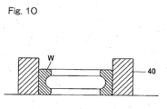
- the ring shaped article W is cooled down to a temperature near to a martensitic transformation point (martensitic transformation temperature: 230°C) without being restrained in any arresting die; when it is cooled down to such temperature, the ring shaped article W is placed inside the arresting die 40 and is then cooled down to a predetermined temperature (about 110°C); after the ring shaped article W has been cooled down to such temperature, the ring shaped article W is removed from the arresting die 40; and thereafter the ring shaped article W is allowed to cool naturally down to room temperature.
- a quenching temperature about 850°C
- the method has been suggested, in which using the arresting die of an axially elongated and vertically extending cylindrical configuration, a ring shaped article then at a cooling step of the quenching process is forcibly inserted into the vertically cylindrical arresting die sequentially from above so that the ring shaped article within the arresting die can be pushed sequentially outwardly from below.
- Patent Document 1 JP Laid-open Patent Publication No. H09-176740
- the deformation correcting method utilizing the arresting die as hereinabove described requires the arresting die, which tends to incur a high manufacturing cost, to be prepared for each of ring shaped articles of different dimensions. Also, a work of mounting the ring shaped article in the arresting die and a work of removing the ring shaped article from the arresting die after completion of the quenching require a substantial amount of labor.
- JP-A-2007138223 discloses a method of die-quenching a ring shaped article, which comprises: a heating step of heating the ring shaped article to a quenching temperature; a primary cooling step of cooling the ring shaped article, which has been heated to the quenching temperature, down to a deformation correction initiating temperature, which is higher than a martensitic transformation point; and a secondary cooling step of cooling the ring shaped article, which has been cooled down to the deformation correction initiating temperature, down to a temperature lower than the martensitic transformation point under a state of pressing dies against an outer peripheral surface of the ring type article.
- a continuous heating furnace largely employed in the conventional quenching apparatus has such problems that it requires the use of a substantial length of the path of travel of an article to be heated in order for the latter to be heated to a quenching temperature and that the equipment tends to become bulky in size. Accordingly, it has been desired that the quenching method and the quenching apparatus, both based on the foregoing technology, require the heating time, which is short, and heating facilities which are compact.
- An object of the present invention is to provide a method of, and an apparatus for, quenching a ring shaped article, in which thermal deformation of the ring shaped article, which occurs as a result of the quenching treatment, can be corrected during the quenching treatment of such ring shaped article; such correction of the thermal deformation can be accomplished without substantially requiring a cost and a labor and can be applied to ring shaped articles of varying sizes; the ring shaped article can be efficiently heated to the quenching temperature; the required heating time is short; and the required equipment is compact.
- a method of quenching a ring shaped article in accordance with the present invention includes a heating step of heating the ring shaped article to a quenching temperature; a primary cooling step of cooling the ring shaped article, which has been heated to the quenching temperature, down to a deformation correction initiating temperature, which is higher than a martensitic transformation point; and a secondary cooling step of cooling the ring shaped article, which has been cooled down to the deformation correction initiating temperature, down to a temperature lower than the martensitic transformation point by, while a pair of receiving rolls are held in contact with an outer peripheral surface of such ring shaped article for rotation about an axis of rotation, which is parallel to a center of the ring shaped article, pressing a press roll, rotatable about an axis of rotation parallel to the center of the ring shaped article, against the outer peripheral surface of the ring shaped article from one side of the ring shaped article opposite to a point intermediate between the receiving rolls.
- the press roll then rotating is urged against the outer peripheral surface of the ring shaped articles from the opposite side of the receiving rolls, the ring shaped article is cooled.
- the deformation occurring in the ring shaped article can be corrected with the circularity increased consequently.
- This deformation correction is performed with no use of any arresting die and, therefore, no cost is incurred in utilizing the arresting die and neither a work to mount the ring shaped article on the arresting die nor a work to remove the ring shaped article from the arresting die is required. Since the deformation correction is performed during the secondary cooling step, no extra step for the deformation correction need not be employed.
- the heating step is carried out by induction heating.
- the required heating equipment can be compactized as compared with the heating performed by the use of a continuous heating furnace.
- the heating step includes a preheating step of heating by induction heating the ring shaped article to a predetermined preheating temperature near to the quenching temperature and a soaking step of heating the ring shaped article, which has been heated to the preheating temperature, to the quenching temperature within a continuous heating furnace.
- the ring shaped article since the ring shaped article is heated to the quenching temperature with the use of the preheating step for heating by induction heating and the soaking step for heating within a continuous heating furnace, the ring shaped article can be heated deep by induction heating in a matter of minutes with a good energy efficiency and, also, due to the use of the continuous heating furnace, the ring shaped article in its entirety can be soaked.
- the continuous heating furnace is used only for the purpose of heating the ring shaped article, which has been preheated to a temperature near to the quenching temperature, to the quenching temperature, and, therefore, the heating time can be reduced considerably in contrast to that required to heat from room temperature and the path of transport, through which the ring shaped article is transported within the furnace, may be short and, therefore, resulting in reduction of the size of the equipment.
- an oil bath for cooling the ring shaped article during the primary cooling step and an oil bath for cooling the ring shaped article during the secondary cooling step may be used separately.
- the separate use of the cooling oil bath in the primary cooling step and the cooling oil bath in the secondary cooling step is advantageous in that the cooling of the ring shaped article during the primary cooling step, loading of the ring shaped article in between the pair of the receiving rolls and the press roll and the cooling of the ring shaped article during the secondary cooling step can be performed continuously in series with each other. Also, the quenching process line can be designed in a simple configuration.
- the length of time during which the press roll is urged against the outer peripheral surface of the ring shaped article is preferably within the range of 40 to 90 seconds.
- the temperature of the ring shaped article at the time a deformation correction is initiated with the press roll urged against the outer peripheral surface of the ring shaped article is preferably 20°C to 50°C higher than the martensitic transformation point.
- the length of time during which the deformation correction is carried out with the press roll urged against the outer peripheral surface of the ring shaped article is preferred within the range of 40 to 90 seconds. Also, in order to complete the deformation correction during the cooling step for quenching while the above described length of time during which the deformation correction is carried out is secured, it has been found preferred that urging of the press roll has to be initiated from the temperature that is 20°C to 50°C higher than the martensitic transformation point.
- An apparatus for quenching a ring shaped article includes a heating station for heating the ring shaped article to a quenching temperature; a primary cooling station for cooling the ring shaped article, which has been heated to the quenching temperature by the heating station, down to a deformation correction initiating temperature, which is higher than a martensitic transformation point; and a secondary cooling station for cooling the ring shaped article, which has been cooled down to the deformation correction initiating temperature by the primary cooling station, down to a temperature lower than the martensitic transformation point by, while a pair of receiving rolls are held in contact with an outer peripheral surface of such ring shaped article for rolling motion about an axis of rotation, which is parallel to a center of the ring shaped article, pressing a press roll, rotatable about an axis of rotation parallel to the center of the ring shaped article, against the outer peripheral surface of the ring shaped article from one side of the ring shaped article opposite to a point intermediate between the receiving rolls
- the ring shaped article quenching apparatus the ring shaped article is cooled at the secondary cooling station in a condition in which while the pair of the receiving rolls are rotatably held in contact with the outer peripheral surface of the ring shaped article, the press roll then rotating is urged against the outer peripheral surface of the ring shaped article from the opposite side.
- the deformation occurring in the ring shaped article can be corrected with the circularity increased consequently.
- the apparatus can be suited to the ring shaped articles of varying sizes.
- This deformation correction is performed with no use of any arresting die and, therefore, no cost is incurred in utilizing the arresting die and neither a work to mount the ring shaped article on the arresting die nor a work to remove the ring shaped article from the arresting die is required. Since the deformation correction is performed during the secondary cooling step, no extra step for the deformation correction need not be employed.
- the heating station is operable to perform an induction heating.
- the required heating equipment can be compactized as compared with the heating performed by the use of a continuous heating furnace.
- the heating station includes a preheating station for heating by induction heating the ring shaped article to a predetermined preheating temperature near to the quenching temperature and a soaking station for heating the ring shaped article, which has been heated to the preheating temperature, to the quenching temperature within a continuous heating furnace.
- the ring shaped article since the ring shaped article is heated to the quenching temperature with the use of the preheating station, at which heating by induction heating takes place, and the soaking station, at which heating takes place within a continuous heating furnace, the ring shaped article can be heated deep by induction heating in a matter of minutes with a good energy efficiency and, also, due to the use of the continuous heating furnace, the ring shaped article in its entirety can be soaked.
- the continuous heating furnace is used only for the purpose of heating the ring shaped article, which has been preheated to a temperature near to the quenching temperature, to the quenching temperature, and, therefore, the heating time can be reduced considerably in contrast to that required to heat from room temperature and the path of transport, through which the ring shaped article is transported within the furnace, may be short and, therefore, resulting in reduction of the size of the equipment.
- the secondary cooling station of the ring shaped article quenching apparatus referred to above makes use of a ring shaped article deformation correcting device for correcting a deformation of the ring shaped article while the ring shaped article once heated is cooled, which device includes a support table, on which the ring shaped article in a heated condition is placed; a pair of receiving rolls, which rollingly contact an outer peripheral surface of the ring shaped article on the support table; a press roll provided in opposition to the pair of the receiving rolls with the ring shaped article intervening therebetween; a press roll drive mechanism for driving the press roll between an advanced position, at which the press roll is urged against the outer peripheral surface of the ring shaped article, and a retracted position, at which the press roll is separated away from the outer peripheral surface of the ring shaped article; and a press roll rotating mechanism for rotating the press roll then urged against the ring shaped article by the press roll drive mechanism.
- the deformation correcting device since the correction of deformation is performed during the cooling step for quenching, the deformation correcting device can be disposed without increasing the number of process steps of the manufacturing line for the ring shaped article.
- the deformation correcting device it is recommended to use a roll interval adjusting mechanism for adjusting the interval between the receiving rolls. If the interval between the receiving rolls of that pair is adjustable, it is possible to render the apparatus to suit to a further varying size of the ring shaped article.
- the deformation correcting time cooling mechanism may include a support unit for tiltably supporting the support table such that a ring shaped article support area of the support table, where the ring shaped article is placed, may be lowered, and a tilting unit for tilting the support table supported by the support unit, so that when the support table is tilted by the tilting unit, the ring shaped article can be immersed into the quenching oil within the oil bath.
- the provision of the deformation correcting time cooling mechanism is effective to allow the ring shaped article to be corrected to remove the deformation while being sufficiently cooled. If the deformation correcting time cooling mechanism is made up of the support unit and the tilting unit, the ring shaped article can be assuredly immersed into the quenching oil contained within the oil bath to cool it even though it is a simplified construction.
- the quenching apparatus for quenching the ring shaped article is generally identified by 30 and includes a heating station 31, a primary cooling station 32, a secondary cooling station 33, and a cleansing station 34.
- the heating station 31 makes use of a heating furnace or the like to heat the ring shaped article W to a quenching temperature (for example, 850°C) (a heating step S1).
- the primary cooling station 32 is for primarily cooling the ring shaped article W, which has been heated to the quenching temperature, down to a temperature (for example, 290°C), which is higher than the martensitic transformation point, by immersing such ring shaped article W within a quenching oil contained in a primary cooling bath 32a (a primary cooling step S2).
- the secondary cooling station 33 is for secondarily cooling the ring shaped article W, which has been primarily cooled, down to a predetermined temperature (for example, 110°C) by immersing a quenching oil, contained in an oil bath 20, while a deformation correction is performed by means of a deformation correcting device 1 (a secondary cooling step S3).
- the cleansing station 34 is for cleansing the ring shaped article W, which has been secondarily cooled, and then transferring it to the subsequent processing step.
- the primary cooling bath 32a of the primary cooling station 32 has an oil accommodating portion of a U-shaped sectional shape having opposite ends that define an introducing area 32aa and a delivery area 32ab, respectively, which oil accommodating portion is so designed that the ring shaped article W can be transported from the introducing area 32aa at one end thereof towards the delivery area 32ab at the opposite end thereof by means of an elevator 32b.
- a space 32c above the introducing area 32aa is rendered to be a closed space filled with a nitrogen gas N 2 .
- An open/close door 32d is provided between the space 32c and the heating station 31.
- this primary cooling bath 32a the ring shaped article W heated by the heating station 31 is immediately loaded into the space 32c filled with the nitrogen gas N 2 and is subsequently immersed into the quenching oil, and, accordingly, the cooling can be readily performed without the ring shaped article W being exposed to the atmosphere.
- the deformation correcting device 1 of the secondary cooling station 33 includes a support table 2 for the support of the ring shaped article W thereon, and a pair of receiving rolls 3 and a press roll 4 mounted on the support table 2.
- the receiving rolls 3 are rotatably mounted on respective support shafts 3a protruding upwardly from associated receiving roll support members 7.
- the press roll 4 is mounted on a press roll support shaft 4a for rotation together therewith, which shaft 4a protrudes upwardly from a press roll support member 11 and is rotatable relative to such press roll support member 11.
- the ring shaped article W is in the form of, for example, a raceway member of a bearing assembly.
- the raceway ring of the bearing assembly is that formed by means of a forging process and has an inner peripheral surface or an outer peripheral surface formed with a raceway groove by means of a grinding process.
- Material for the bearing raceway ring may is, for example, a steel material such as, for example, a bearing steel.
- a portion of the top surface of the support table 2 between the pair of the receiving rolls 3 and the press roll 4 is designed as a ring shaped article support area 5 and a region thereof ranging from one to the other of opposite ends in a direction (Y-axis direction) of arrangement of the receiving rolls 3 is so formed as to lie at a level higher than that of the other portion thereof.
- This ring shaped article support area 5 is formed with a cutout 5a for the purpose of avoiding an interference thereof with the press roll 4 and the press roll support member 11 when the press roll 4 is advanced as will be described later.
- a loading and discharging mechanism (not shown) for loading the ring shaped article W onto the ring shaped article support area 5 from a direction shown by the arrow A and discharging the ring shaped article W from the ring shaped article support area 5 towards a direction shown by the arrow B.
- the pair of the receiving rolls 3 are spaced a distance in the Y-axis direction from each other, which distance can be adjusted by a receiving roll interval adjusting mechanism 6 employed in association with each of the receiving rolls 3.
- the receiving roll interval adjusting mechanism 6 includes the receiving roll support member 7, on which the respective receiving roll 3 is rotatably mounted, a guide 8 for displaceably guiding the receiving roll support member 7 relative to the support table 2 in the Y-axis direction, and a fixing unit 9 for fixing the receiving roll support member 7 to the support table 2.
- this fixing unit 9 for example, a bolt or any fixing jig for fastening by the utilization of a frictional force can be employed.
- the press roll 4 is adapted to be driven between advanced and retracted positions by a press roll drive mechanism 10 in a direction (X-axis direction) along a path passing through a point M intermediate between the receiving rolls 3 and then through the longitudinal axis O of the press roll 4.
- the press roll drive mechanism 10 includes the press roll support member 11 for rotatably supporting the press roll 4 as hereinbefore described, X-axis direction guide rods 12 along which respective to-be-guided elements 11a, mounted on the press roll support member 11, are mounted for movement relative thereto, and a drive unit 13 for driving the press roll support member 11 in the X-axis direction relative to the support table 2.
- the to-be-guided elements 11a serve to guide the associated guide rods 12 by the effect of, for example, a sliding guide or a rolling guide.
- the drive unit 13 is comprised of, for example, a hydraulic cylinder.
- the press roll 4 is also adapted to be rotated by a press roll rotating mechanism 15 in a predetermined direction.
- This press roll rotating mechanism 15 is of a structure, in which a rotating motor 16 is mounted on the press roll support member 11 and a drive chain 19 is trained between a sprocket 17, mounted on an output shaft of the rotating motor 16, and a sprocket 18 mounted on the support shaft of the press roll 4.
- an oil bath for cooling the ring shaped article is disposed below the ring shaped article support area 5 of the support table 2, and the ring shaped article W resting on the ring shaped article support area 5 can be immersed into the quenching oil contained in this oil bath 20.
- a deformation correcting time cooling mechanism 21 therefor is made up of a support unit 22 for supporting the support table 2 so that one side of the support table 2 adjacent the ring shaped article support area 5 can be tiltably lowered, and a tilting unit 23 for tilting the support table 2 supported by this support unit 22.
- the support unit 22 is of a structure, in which a horizontally extending tilt center shaft 22a, protruding outwardly from opposite Y-axis direction sides of the support table 2 can be rotatably supported by corresponding pivot support members 22.
- the tilting unit 23 is comprised of a hydraulic cylinder provided between a lower surface of the support table 2, positioned on one side of the tilt center shaft 22a opposite to the ring shaped article support area 5, and a floor surface 24. As shown by the solid line in Fig. 2B , when the support table 2 is tilted by the drive of the tilting unit 23, the ring shaped article W resting on the ring shaped article support area 5 can be immersed into the oil within the oil bath 20.
- the deformation correction accomplished by the deformation correcting device 1 at the secondary cooling station 33 shown in Fig. 1 , will now be described with particular reference to Figs. 2A and 2B .
- the deformation correcting device 1 is held standby at a retracted position P1 with the press roll 4 having been retracted relative to the receiving rolls 3 as shown by the chain line in Fig. 2A .
- the support table 2 is held in a horizontal condition.
- the ring shaped article W shown by the chain line and emerging outwardly from the primarily cooling bath 32a shown in Fig.
- the drive unit 13 of the press roll drive mechanism 10 is driven to advance the press roll 4 to an advanced position P2.
- the ring shaped article W is held by the pair of the receiving rolls 3 and the press roll 4 with its outer peripheral surface restrained from both sides of the X-axis direction.
- the press roll 4 is driven to rotate the press roll 4 in the predetermined direction. While the ring shaped article W is restrained under a predetermined load by the pair of the receiving rolls 3 and the press roll 4 from the opposite sides, the ring shaped article W is rotated between the rolls 3 and 4 so that a deformation can be corrected to allow the ring shaped article W to have an increased circularity.
- the tilting unit 23 of the deformation correcting time cooling mechanism 21 is driven to tilt the support table 2 with the ring shaped article support area 5 lowered consequently. Accordingly, the ring shaped article W is immersed into the quenching oil contained in the oil bath 20 and is therefore secondarily cooled. Since loading of the ring shaped article W onto the ring shaped article support area 5, advance of the press roll 4, rotation of the press roll 4 and tilting of the support table 2 take place continuously, the primary cooling and the secondary cooling are performed with no substantial time spent therebetween. For this reason, quenching takes place favorably.
- the temperature of the ring shaped article W at the time the deformation correction is initiated with the press roll 4 urged against the outer peripheral surface of the ring shaped article W is chosen to be a temperature 20°C to 50°C higher than the martensitic transformation point. It is to be noted that the time of deformation correction is to be construed as meaning the time span between the time, at which pressing by the press roll 4 is initiated, and the time at which it is completed. Also, the length of time during which the deformation correction is carried out with the outer peripheral surface of the ring shaped article W urged by the press roll 4, is chosen to be about 40 to 90 seconds.
- the ring shaped article W of the above described temperature When the ring shaped article W of the above described temperature is immersed only for the above described length of time into the quenching oil within the oil bath 20, the ring shaped article W is cooled down substantially to a target cooling temperature (for example, 110°C) of the secondary cooling. Accordingly, with no waste of time, the deformation correction and the secondary cooling are carried out.
- the support table 2 Upon completion of the deformation correction and the secondary cooling, the support table 2 is again returned to the initial, horizontal condition and the rotation of the press roll 4 is halted, followed by retraction of the press roll 4 back to the retracted position P1, at which time the ring shaped article W is released.
- the ring shaped article W so released is, by the action of the loading and discharging mechanism (not shown), discharged in a direction, shown by B in Fig. 2A , from the ring shaped article support area 5 of the support table 2 to the outside of the support table 2.
- the deformation correcting device 1 of the construction described above designed for the ring shaped article is such that since the press roll 4 can be selectively movable between the advanced and retracted positions, the distance between the pair of the receiving rolls 3 and the press roll 4 can be changed as desired. For this reason, it can be applied to ring shaped articles W of any varying diameters.
- the spacing between the receiving rolls 3 may be changed by the receiving roll interval adjusting mechanism 6 to suit to the size of the ring shaped article W.
- the deformation correction of the ring shaped article W by the deformation correcting device 1 require no allowance for a die, since no arresting die is utilized, and, also, no work is required to mount the ring shaped article W onto the die nor remove it from the die.
- the quenching apparatus 30 of the present invention is such that since the deformation correction is carried out during the secondary cooling step S3 by the deformation correcting device 1 of the secondary cooling station 33, there is no need to provide an extra step of deformation correction. Since the primary cooling oil bath 32a of the primary cooling station 32 and the secondary cooling oil bath 20 of the secondary cooling station 33 are separate from each other, it is possible to consecutively perform the cooling of the ring shaped article W at the primary cooling station 32, the loading of the ring shaped article W in between the pair of the receiving rolls 3 and the press roll 4, and the cooling of the ring shaped article W at the secondary cooling station 33. Also, the processing line of the quenching apparatus 30 can be simplified in structure.
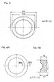
- the amount of change in outer diameter ⁇ D represents the difference between the outer diameter D1 before the deformation correction and the outer diameter D2 after the deformation correction ( Fig. 3 ).
- the amount of change in wall thickness ⁇ T represents the difference between the wall thickness T1 before the deformation correction and the wall thickness T2 after the deformation correction ( Figs. 4A and 4B ).
- the average value x, the standard deviation value ⁇ and the maximum value Max were determined. Results of those tests are tabulated in Table 1 below. Table 1 230°C 250°C 280°C Load X ⁇ Max X ⁇ Max X ⁇ Max 150 kgf Amt. of Outer Dia.
- Figs. 5 to 8A and 8B illustrate the apparatus used to execute such quenching method.
- the second preferred embodiment is basically similar in structure to that according to the previously described first embodiment except that heating performed by the heating station 31 used during the heating step S1 in the practice of the previously described first embodiment is carried out by means of induction heating. Accordingly, component parts employed in the second embodiment, but similar to those in the first embodiment are shown by like reference numerals and the details are not therefore reiterated for the sake of brevity. As shown in Fig.
- the ring shaped article quenching apparatus 30 employed in the practice of the second embodiment of the present invention includes a pre-cleansing station 34A, a heating station 31, a primary cooling station 32, a secondary heating station 33 and a post-cleansing station 34B.
- the ring shaped article W which has been pre-cleansed at the pre-cleansing station 34A is heated by induction heating to a predetermined quenching temperature (for example, 850°C) by an induction heating device 50 (a heating step S1).
- a predetermined quenching temperature for example, 850°C
- the ring shaped article W which has been heated to the quenching temperature, is immersed in the quenching oil contained in the primary cooling bath 32a so that the ring shaped article W can be primarily cooled down to a temperature (for example, 290°C) that is higher than the martensitic transformation point (a primary cooling step S2).
- a temperature for example, 290°C
- the ring shaped article W which has been primarily cooled, is immersed into the quenching oil within the oil bath 20 while deformation thereof is corrected by the deformation correcting device 1, so that the ring shaped article W can be secondarily cooled down to a predetermined temperature (for example, 110°C) (a secondary cooling step S3).
- a predetermined temperature for example, 110°C
- This induction heating device 50 includes a rotary table 51 for turning a ring shaped article W, placed on such rotary table 51, about a ring center 01, a heating coil 52 and an alternating current power source 53 for supplying an electric current to the heating coil 52.
- the alternating current power source 53 is rendered to be, for example, a high frequency power source.
- a heating chamber 37, in which the induction heating device 50 is installed, is of an atmosphere filled with a nitrogen gas N 2 .
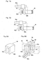
- the heating coil 52 is of a downwardly oriented U-shaped configuration structured so as to straddle between inner and outer peripheral sides of the ring shaped article W as best shown in, for example, Figs. 6 and 7A and 7B . Opposite arms 52a and 52b of the heating coil 52 have their free ends connected across the alternating current power source 53.
- Fig. 8A illustrates a perspective view of the heating coil 52 shown in Figs. 6 and 7A and 7B .
- such a structure may be employed, in which as best shown in Fig. 8B , two U-shaped conductors 65 and 66 are so arranged as to permit their leg conductors 65a, 65b, 66a and 66b to extend parallel to each other, one of the leg conductors 65a and 66a have their free ends connected with each other through a connecting conductor 67, and the other of the leg conductors 65b and 66b have their free ends provided with respective lead portions 65c and 66c, which are in turn connected across the alternating power source 53.
- the heating coil 52 is so arranged that the position thereof can be adjustable in a direction radially of the rotary table 51 relative to a heating coil support body 54.
- the heating coil support body 54 includes, for example, a guide rod 54a extending in a direction radially of the rotary table 51, and the heating coil 52 can be adjusted in position continuously along this guide rod 54a.
- the heating coil 52 is fixed in position to the guide rod 54a by means of, for example, a bolt (not shown) or the like.
- the position of the heating coil 52 is adjustable, the position of the heating coil 52 can be changed to suit to a relatively small ring shaped article W as is the case with a first example shown in Fig. 7A , or the position of the heating coil 42 can be changed to suit to a relatively large ring shaped article W as is the case with a second example shown in Fig. 7B .
- a contact pedestal 51a is provided in the rotary table 51 for the purpose of reducing the surface area of contact with the ring shaped article W.
- This contact pedestal 51a is rendered to be replaceable with another one depending on the diameter of the ring shaped article W.
- the rotary table 51 is rotationally driven by a rotary table rotating device 55 and can be also moved by a rotary table elevating device 56 between a position, at which the ring shaped article W placed on the rotary table 51 enters in between the opposite arms 52a and 52b of the heating coil 52, and a position in which such ring shaped article W departs from a space between the opposite arms 52a and 52b of the heating coil 52.
- the rotary table 51 is rotatably provided on an elevating frame 57 through bearings 58, and the elevating frame 57 is arranged on a base support 59 through an elevation guide member 60 for movement up and down along the elevation guide member 60.
- the elevating frame 57 is drivingly coupled with an elevating drive source 61 such as, for example, a hydraulic cylinder and, accordingly, the rotary table 51 is moved up and down by the elevating drive source 61 together with the elevating frame 57.
- the rotary table rotating device 55 is made up of a motor 62 and a rotation transmitting mechanism 63 such as, for example, pulleys or a gear train for transmitting the rotation of the motor 62 to a shaft 51b of the rotary table 51.
- a rotation transmitting mechanism 63 such as, for example, pulleys or a gear train for transmitting the rotation of the motor 62 to a shaft 51b of the rotary table 51.
- the heating facility can be compactized as compared with the heating with the use of a continuous heating furnace.
- Other functions and effects are similar to those afforded by the previously described first embodiment.
- Fig. 9 illustrates the apparatus used to execute such quenching method.
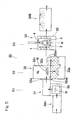
- the third preferred embodiment is basically similar in structure to that according to the previously described first embodiment, except that the heating step S employed in the practice of the previously described first embodiment is divided into two steps, i.e., a preheating step S1A, including a preheating station 31A, and a soaking step S1B including a soaking station 31B. Accordingly, component parts employed in the third embodiment, but similar to those in the first embodiment may be occasionally shown by like reference numerals and the details are not therefore reiterated for the sake of brevity. As shown in Fig.
- the ring shaped article quenching apparatus 30 includes a pre-cleansing station 34A, a preheating station 31A, a soaking station 31B, a primary cooling station 32, a secondary cooling station 33 and a post-cleansing station 34B.
- the pre-cleansing station 34A swarfs and oil content, which adhere to the ring shaped article W during a turning process, are cleansed off.
- the ring shaped article W which has been pre-cleansed at the pre-cleansing station 34A, is heated by induction heating to a predetermined preheating temperature, which is near to the quenching temperature, by an induction heating device 50 (a heating step S1A).
- the ring shaped article W which has been heated to the preheating temperature, is heated to a predetermined quenching temperature (for example, 850°C) within the continuous heating furnace 31a (a soaking step S1B).
- the ring shaped article W which has been heated to the quenching temperature, is immersed in the quenching oil contained in the primary cooling bath 32a so that the ring shaped article W can be primarily cooled down to a temperature (for example, 290°C) that is higher than the martensitic transformation point (a primary cooling step S2).
- a primary cooling step S2 the ring shaped article W, which has been primarily cooled, is immersed into the quenching oil within the oil bath 20 while deformation thereof is corrected by the deformation correcting device 1, so that the ring shaped article W can be secondarily cooled down to a predetermined temperature (for example, 110°C) (a secondary cooling step S3).
- the post-cleansing station 34B the ring shaped article W, which has been secondarily cooled, is transferred to the subsequent processing step.
- the induction heating device 50 employed at the preheating station 31A used in the practice of the third preferred embodiment is of a structure identical with the induction heating device 50 employed at the heating station 31 used in the practice of the previously described second preferred embodiment and, therefore, the details thereof are not reiterated for the sake of brevity, but there is such a difference that in contrast to the use of the induction heating device 50 at the preheating station 31A according to the third embodiment for the purpose of heating by induction heating of the ring shaped article to the predetermined preheating temperature near to the quenching temperature, the heating station 31 according to the previously described second embodiment makes use of the induction heating device 50 for the purpose of heating to the quenching temperature.
- the structure and the description of the heating coil 52 shown in Figs. 7A and 7B and Figs. 8A and 8B are also equally applicable to the third preferred embodiment of the present invention and, therefore, the details thereof are not reiterated for the sake of brevity.
- the continuous heating furnace 31a at the soaking station 31B is a furnace for heating the ring shaped articles W while the latter are transported successively in a row by a transport unit 31b such as, for example, a conveyor within the interior of such furnace that is kept under a high temperature atmosphere.
- a transport unit 31b such as, for example, a conveyor within the interior of such furnace that is kept under a high temperature atmosphere.
- the quenching apparatus 30 of the third embodiment of the present invention since heating is effected to the quenching temperature through the preheating station 31A, at which the heating takes place by means of induction heating, and also through the soaking station 31B, at which the heating takes place by means of the continuous heating furnace 31a, the ring shaped article W can be heated deep by induction heating in a matter of minutes with a good energy efficiency and, also, due to the use of the continuous heating furnace 31a, the ring shaped article W in its entirety can be soaked.
- the continuous heating furnace 31a Since although the use is made of the continuous heating furnace 31a, the continuous heating furnace 31a is used only for the purpose of heating the ring shaped article W, which has been preheated to a temperature near to the quenching temperature, to the quenching temperature, the heating time can be reduced considerably in contrast to that required to heat from room temperature. Also, the path of transport, through which the ring shaped article W is transported within the furnace, may be short and, therefore, the equipment can be reduced in size.
- the deformation correcting device 1 according to any one of the foregoing embodiments of the present invention can be embodied in the following modes.
- a deformation correcting device for correcting a deformation occurring in a ring shaped article, which has been heated, while the heated ring shaped article is cooled, which device comprises a support table, on which the ring shaped article in a heated condition is placed; a pair of receiving rolls, which rollingly contact an outer peripheral surface of the ring shaped article on the support table; a press roll provided in opposition to the pair of the receiving rolls with the ring shaped article intervening therebetween; a press roll drive mechanism for driving the press roll between an advanced position, at which the press roll is urged against the outer peripheral surface of the ring shaped article, and a retracted position, at which the press roll is separated away from the outer peripheral surface of the ring shaped article; and a press roll rotating mechanism for rotating the press roll then urged against the ring shaped article by the press roll drive mechanism.
- the ring shaped article deformation correcting device as defined in Mode 1 above, further comprising a roll interval adjusting mechanism for adjusting the interval between the receiving rolls.
- the ring shaped article deformation correcting device as defined in Mode 1 above, in which the length of time required to perform a deformation correction with the press roll urged against the outer peripheral surface of the ring shaped article is within the range of 40 to 90 seconds.
- the ring shaped article deformation correcting device as defined in Mode 1 above, in which the temperature of the ring shaped article at the time a deformation correction is initiated with the press roll urged against the outer peripheral surface of the ring shaped article is 20°C to 50°C higher than the martensitic transformation point.
- the ring shaped article deformation correcting device as defined in Mode 1 above, further comprising an oil bath for cooling purpose and a deformation correcting time cooling mechanism for immersing the ring shaped article into a quenching oil, contained within the oil bath, at the time of deformation correction to thereby cool the ring shaped article.
- the deformation correcting time cooling mechanism comprises a support unit for tiltably supporting the support table such that a ring shaped article support area of the support table, where the ring shaped article is placed, may be lowered, and a tilting unit for tilting the support table supported by the support unit, so that when the support table is tilted by the tilting unit, the ring shaped article can be immersed into the quenching oil within the oil bath.
- the ring shaped article deformation correcting device as defined in Mode 1 above, in which the ring shaped article is a raceway ring of a bearing assembly.
Landscapes
- Chemical & Material Sciences (AREA)
- Engineering & Computer Science (AREA)
- Mechanical Engineering (AREA)
- Crystallography & Structural Chemistry (AREA)
- Materials Engineering (AREA)
- Metallurgy (AREA)
- Organic Chemistry (AREA)
- Physics & Mathematics (AREA)
- Thermal Sciences (AREA)
- General Engineering & Computer Science (AREA)
- Manufacturing & Machinery (AREA)
- Heat Treatment Of Articles (AREA)
Description
- The present invention relates to a method of quenching a ring shaped article such as, for example, a bearing raceway ring or the like, which is performed while correction of a thermal deformation of the ring shaped article is carried out, and an apparatus accomplishing such quenching.
- If such a ring shaped article as a raceway ring or the like of a bearing assembly is quenched, a deviation may occur in the circularity as a result of thermal deformation. For this reason, after the quenching, a process of correcting such deformation is generally practiced with the use of a ring shaped deformation correcting jig.
- However, if correction of the deformation is carried out at a process step separate from the step of quenching, the number of process steps in the manufacturing line for the production of ring shaped articles will increase and, therefore, as shown in
Fig. 10 , the deformation is corrected when quenching by cooling the ring shaped article W inserted into an arrestingdie 40. More specifically, after the ring shaped article W has been heated to a quenching temperature (about 850°C), the ring shaped article W is cooled down to a temperature near to a martensitic transformation point (martensitic transformation temperature: 230°C) without being restrained in any arresting die; when it is cooled down to such temperature, the ring shaped article W is placed inside the arrestingdie 40 and is then cooled down to a predetermined temperature (about 110°C); after the ring shaped article W has been cooled down to such temperature, the ring shaped article W is removed from the arrestingdie 40; and thereafter the ring shaped article W is allowed to cool naturally down to room temperature. - Also, as one method of correcting the deformation with the use of the arresting die, the method has been suggested, in which using the arresting die of an axially elongated and vertically extending cylindrical configuration, a ring shaped article then at a cooling step of the quenching process is forcibly inserted into the vertically cylindrical arresting die sequentially from above so that the ring shaped article within the arresting die can be pushed sequentially outwardly from below. (See the
Patent Document 1 listed below.) - [Patent Document 1]
JP Laid-open Patent Publication No. H09-176740 - It has, however, been found that the deformation correcting method utilizing the arresting die as hereinabove described requires the arresting die, which tends to incur a high manufacturing cost, to be prepared for each of ring shaped articles of different dimensions. Also, a work of mounting the ring shaped article in the arresting die and a work of removing the ring shaped article from the arresting die after completion of the quenching require a substantial amount of labor. In the case of the deformation correcting method disclosed in the
Patent Document 1 referred to above, no work of removing the ring shaped article from the arresting die is needed, but since in this method, the ring shaped article is retained within the arresting die by the effect of a frictional force developed between the arresting die and the ring shaped article, there is the possibility that the ring shaped article of a large dimension tends to fall downwards from the arresting die by the effect of its own weight and, therefore, such method is merely applicable to ring shaped articles of a relatively small dimension. - In view of the above, it has been desired to develop the technology by which without incurring any cost and a labor, thermal deformation of ring shaped articles of varying sizes can be corrected.
-
JP-A-2007138223 - Also, a continuous heating furnace largely employed in the conventional quenching apparatus has such problems that it requires the use of a substantial length of the path of travel of an article to be heated in order for the latter to be heated to a quenching temperature and that the equipment tends to become bulky in size. Accordingly, it has been desired that the quenching method and the quenching apparatus, both based on the foregoing technology, require the heating time, which is short, and heating facilities which are compact.
- An object of the present invention is to provide a method of, and an apparatus for, quenching a ring shaped article, in which thermal deformation of the ring shaped article, which occurs as a result of the quenching treatment, can be corrected during the quenching treatment of such ring shaped article; such correction of the thermal deformation can be accomplished without substantially requiring a cost and a labor and can be applied to ring shaped articles of varying sizes; the ring shaped article can be efficiently heated to the quenching temperature; the required heating time is short; and the required equipment is compact.
- A method of quenching a ring shaped article in accordance with the present invention includes a heating step of heating the ring shaped article to a quenching temperature; a primary cooling step of cooling the ring shaped article, which has been heated to the quenching temperature, down to a deformation correction initiating temperature, which is higher than a martensitic transformation point; and a secondary cooling step of cooling the ring shaped article, which has been cooled down to the deformation correction initiating temperature, down to a temperature lower than the martensitic transformation point by, while a pair of receiving rolls are held in contact with an outer peripheral surface of such ring shaped article for rotation about an axis of rotation, which is parallel to a center of the ring shaped article, pressing a press roll, rotatable about an axis of rotation parallel to the center of the ring shaped article, against the outer peripheral surface of the ring shaped article from one side of the ring shaped article opposite to a point intermediate between the receiving rolls. The ring shaped article referred to above may be, for example, a raceway ring employed in a bearing assembly.
- According to this ring shaped article quenching method, during the second cooling step, while the pair of the receiving rolls are rotatably held in contact with the outer peripheral surface of the ring shaped article, the press roll then rotating is urged against the outer peripheral surface of the ring shaped articles from the opposite side of the receiving rolls, the ring shaped article is cooled. In view of the fact that the ring shaped article is turned between the receiving rolls and the press roll while sandwiching between the receiving rolls and the press roll under a predetermined load, the deformation occurring in the ring shaped article can be corrected with the circularity increased consequently. When the interval between the receiving rolls and the press roll is adjusted, the apparatus can be suited to the ring shaped articles of varying sizes. This deformation correction is performed with no use of any arresting die and, therefore, no cost is incurred in utilizing the arresting die and neither a work to mount the ring shaped article on the arresting die nor a work to remove the ring shaped article from the arresting die is required. Since the deformation correction is performed during the secondary cooling step, no extra step for the deformation correction need not be employed.
- In the practice of the present invention, the heating step is carried out by induction heating.
- According to this construction, since during the heating step, heating is performed by induction heating to the quenching temperature, the required heating equipment can be compactized as compared with the heating performed by the use of a continuous heating furnace.
- In the practice of the present invention, the heating step includes a preheating step of heating by induction heating the ring shaped article to a predetermined preheating temperature near to the quenching temperature and a soaking step of heating the ring shaped article, which has been heated to the preheating temperature, to the quenching temperature within a continuous heating furnace.
- According to this construction, since the ring shaped article is heated to the quenching temperature with the use of the preheating step for heating by induction heating and the soaking step for heating within a continuous heating furnace, the ring shaped article can be heated deep by induction heating in a matter of minutes with a good energy efficiency and, also, due to the use of the continuous heating furnace, the ring shaped article in its entirety can be soaked. Although the use is made of the continuous heating furnace, such continuous heating furnace is used only for the purpose of heating the ring shaped article, which has been preheated to a temperature near to the quenching temperature, to the quenching temperature, and, therefore, the heating time can be reduced considerably in contrast to that required to heat from room temperature and the path of transport, through which the ring shaped article is transported within the furnace, may be short and, therefore, resulting in reduction of the size of the equipment.
- In the practice of the present invention, an oil bath for cooling the ring shaped article during the primary cooling step and an oil bath for cooling the ring shaped article during the secondary cooling step may be used separately.
- The separate use of the cooling oil bath in the primary cooling step and the cooling oil bath in the secondary cooling step is advantageous in that the cooling of the ring shaped article during the primary cooling step, loading of the ring shaped article in between the pair of the receiving rolls and the press roll and the cooling of the ring shaped article during the secondary cooling step can be performed continuously in series with each other. Also, the quenching process line can be designed in a simple configuration.
- The length of time during which the press roll is urged against the outer peripheral surface of the ring shaped article is preferably within the range of 40 to 90 seconds. Also, the temperature of the ring shaped article at the time a deformation correction is initiated with the press roll urged against the outer peripheral surface of the ring shaped article is preferably 20°C to 50°C higher than the martensitic transformation point.
- As a result of a series of tests conducted, it has been found that the length of time during which the deformation correction is carried out with the press roll urged against the outer peripheral surface of the ring shaped article is preferred within the range of 40 to 90 seconds. Also, in order to complete the deformation correction during the cooling step for quenching while the above described length of time during which the deformation correction is carried out is secured, it has been found preferred that urging of the press roll has to be initiated from the temperature that is 20°C to 50°C higher than the martensitic transformation point.
- An apparatus for quenching a ring shaped article according to the present invention includes a heating station for heating the ring shaped article to a quenching temperature; a primary cooling station for cooling the ring shaped article, which has been heated to the quenching temperature by the heating station, down to a deformation correction initiating temperature, which is higher than a martensitic transformation point; and a secondary cooling station for cooling the ring shaped article, which has been cooled down to the deformation correction initiating temperature by the primary cooling station, down to a temperature lower than the martensitic transformation point by, while a pair of receiving rolls are held in contact with an outer peripheral surface of such ring shaped article for rolling motion about an axis of rotation, which is parallel to a center of the ring shaped article, pressing a press roll, rotatable about an axis of rotation parallel to the center of the ring shaped article, against the outer peripheral surface of the ring shaped article from one side of the ring shaped article opposite to a point intermediate between the receiving rolls.
- According to this ring shaped article quenching apparatus, the ring shaped article is cooled at the secondary cooling station in a condition in which while the pair of the receiving rolls are rotatably held in contact with the outer peripheral surface of the ring shaped article, the press roll then rotating is urged against the outer peripheral surface of the ring shaped article from the opposite side. In view of the fact that the ring shaped article is turned between the receiving rolls and the press roll while sandwiching between the receiving rolls and the press roll under a predetermined load, the deformation occurring in the ring shaped article can be corrected with the circularity increased consequently. When the interval between the receiving rolls and the press roll is adjusted, the apparatus can be suited to the ring shaped articles of varying sizes. This deformation correction is performed with no use of any arresting die and, therefore, no cost is incurred in utilizing the arresting die and neither a work to mount the ring shaped article on the arresting die nor a work to remove the ring shaped article from the arresting die is required. Since the deformation correction is performed during the secondary cooling step, no extra step for the deformation correction need not be employed.
- In this ring shaped article quenching apparatus of the present invention, the heating station is operable to perform an induction heating.
- According to this construction, since at the heating station, heating is performed by induction heating to the quenching temperature, the required heating equipment can be compactized as compared with the heating performed by the use of a continuous heating furnace.
- In this ring shaped article quenching apparatus of the present invention, the heating station includes a preheating station for heating by induction heating the ring shaped article to a predetermined preheating temperature near to the quenching temperature and a soaking station for heating the ring shaped article, which has been heated to the preheating temperature, to the quenching temperature within a continuous heating furnace.
- According to this construction, since the ring shaped article is heated to the quenching temperature with the use of the preheating station, at which heating by induction heating takes place, and the soaking station, at which heating takes place within a continuous heating furnace, the ring shaped article can be heated deep by induction heating in a matter of minutes with a good energy efficiency and, also, due to the use of the continuous heating furnace, the ring shaped article in its entirety can be soaked. Although the use is made of the continuous heating furnace, such continuous heating furnace is used only for the purpose of heating the ring shaped article, which has been preheated to a temperature near to the quenching temperature, to the quenching temperature, and, therefore, the heating time can be reduced considerably in contrast to that required to heat from room temperature and the path of transport, through which the ring shaped article is transported within the furnace, may be short and, therefore, resulting in reduction of the size of the equipment.
- In a preferred embodiment of the present invention, the secondary cooling station of the ring shaped article quenching apparatus referred to above makes use of a ring shaped article deformation correcting device for correcting a deformation of the ring shaped article while the ring shaped article once heated is cooled, which device includes a support table, on which the ring shaped article in a heated condition is placed; a pair of receiving rolls, which rollingly contact an outer peripheral surface of the ring shaped article on the support table; a press roll provided in opposition to the pair of the receiving rolls with the ring shaped article intervening therebetween; a press roll drive mechanism for driving the press roll between an advanced position, at which the press roll is urged against the outer peripheral surface of the ring shaped article, and a retracted position, at which the press roll is separated away from the outer peripheral surface of the ring shaped article; and a press roll rotating mechanism for rotating the press roll then urged against the ring shaped article by the press roll drive mechanism.
- According to this ring shaped article deformation correcting device, since the correction of deformation is performed during the cooling step for quenching, the deformation correcting device can be disposed without increasing the number of process steps of the manufacturing line for the ring shaped article.
- In the deformation correcting device, it is recommended to use a roll interval adjusting mechanism for adjusting the interval between the receiving rolls. If the interval between the receiving rolls of that pair is adjustable, it is possible to render the apparatus to suit to a further varying size of the ring shaped article.
- In the deformation correcting device, it is recommended to use an oil bath for cooling purpose and a deformation correcting time cooling mechanism for immersing the ring shaped article into a quenching oil, contained within the oil bath, at the time of deformation correction to thereby cool the ring shaped article. For example, the deformation correcting time cooling mechanism may include a support unit for tiltably supporting the support table such that a ring shaped article support area of the support table, where the ring shaped article is placed, may be lowered, and a tilting unit for tilting the support table supported by the support unit, so that when the support table is tilted by the tilting unit, the ring shaped article can be immersed into the quenching oil within the oil bath.
- The provision of the deformation correcting time cooling mechanism is effective to allow the ring shaped article to be corrected to remove the deformation while being sufficiently cooled. If the deformation correcting time cooling mechanism is made up of the support unit and the tilting unit, the ring shaped article can be assuredly immersed into the quenching oil contained within the oil bath to cool it even though it is a simplified construction.
- In any event, the present invention will become more clearly understood from the following description of preferred embodiments thereof, when taken in conjunction with the accompanying drawings. However, the embodiments and the drawings are given only for the purpose of illustration and explanation, and are not to be taken as limiting the scope of the present invention in any way whatsoever, which scope is to be determined by the appended claims. In the accompanying drawings, like reference numerals are used to denote like parts throughout the several views, and:
-
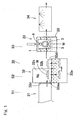
Fig. 1 is a diagram showing a conceptual construction of a quenching apparatus that is employed in executing a method of quenching a ring shaped article according to a first preferred embodiment of the present invention; -
Fig. 2A is a top plan view showing a deformation correcting device employed in the quenching apparatus; -
Fig. 2B is a front elevational view showing the deformation correcting device shown inFig. 2A ; -
Fig. 3 is an explanatory diagram showing the amount of change in outer diameter of the ring shaped article; -
Figs. 4A and 4B are explanatory diagrams showing the amount of change in wall thickness of the ring shaped article; -
Fig. 5 is a diagram showing a conceptual construction of the quenching apparatus used to execute the method of quenching the ring shaped article according to a second preferred embodiment of the present invention; -
Fig. 6 is a front elevational view, with a portion cut out, showing an induction heating device employed at a preheating station in the quenching apparatus; -
Fig. 7A is an explanatory diagram showing a first example of adjusting the position of a heating coil employed in the induction heating device; -
Fig. 7B is an explanatory diagram showing a second example of adjusting the position of the heating coil; -
Fig. 8A is a perspective view showing the heating coil; -
Fig. 8B is a perspective view showing a different heating coil; -
Fig. 9 is a diagram showing a conceptual construction of the quenching apparatus used to execute the method of quenching the ring shaped article according to a third preferred embodiment of the present invention; and -
Fig. 10 is an explanatory diagram showing the conventional deformation correcting method. - A method of quenching a ring shaped article according to a first preferred embodiment of the present invention will be described with particular reference to
Figs. 1 and2A and 2B , which illustrate an apparatus used to execute such quenching method. Referring first toFig. 1 , the quenching apparatus for quenching the ring shaped article is generally identified by 30 and includes aheating station 31, aprimary cooling station 32, asecondary cooling station 33, and acleansing station 34. Theheating station 31 makes use of a heating furnace or the like to heat the ring shaped article W to a quenching temperature (for example, 850°C) (a heating step S1). Theprimary cooling station 32 is for primarily cooling the ring shaped article W, which has been heated to the quenching temperature, down to a temperature (for example, 290°C), which is higher than the martensitic transformation point, by immersing such ring shaped article W within a quenching oil contained in aprimary cooling bath 32a (a primary cooling step S2). Thesecondary cooling station 33 is for secondarily cooling the ring shaped article W, which has been primarily cooled, down to a predetermined temperature (for example, 110°C) by immersing a quenching oil, contained in anoil bath 20, while a deformation correction is performed by means of a deformation correcting device 1 (a secondary cooling step S3). The cleansingstation 34 is for cleansing the ring shaped article W, which has been secondarily cooled, and then transferring it to the subsequent processing step. - In the practice of this first preferred embodiment, the
primary cooling bath 32a of theprimary cooling station 32 has an oil accommodating portion of a U-shaped sectional shape having opposite ends that define an introducing area 32aa and a delivery area 32ab, respectively, which oil accommodating portion is so designed that the ring shaped article W can be transported from the introducing area 32aa at one end thereof towards the delivery area 32ab at the opposite end thereof by means of anelevator 32b. Aspace 32c above the introducing area 32aa is rendered to be a closed space filled with a nitrogen gas N2. An open/close door 32d is provided between thespace 32c and theheating station 31. According to the construction of thisprimary cooling bath 32a, the ring shaped article W heated by theheating station 31 is immediately loaded into thespace 32c filled with the nitrogen gas N2 and is subsequently immersed into the quenching oil, and, accordingly, the cooling can be readily performed without the ring shaped article W being exposed to the atmosphere. - As shown in
Figs. 2A and 2B , thedeformation correcting device 1 of thesecondary cooling station 33 includes a support table 2 for the support of the ring shaped article W thereon, and a pair of receivingrolls 3 and apress roll 4 mounted on the support table 2. The receiving rolls 3 are rotatably mounted on respective support shafts 3a protruding upwardly from associated receivingroll support members 7. Thepress roll 4 is mounted on a press roll support shaft 4a for rotation together therewith, which shaft 4a protrudes upwardly from a pressroll support member 11 and is rotatable relative to such pressroll support member 11. The ring shaped article W is in the form of, for example, a raceway member of a bearing assembly. The raceway ring of the bearing assembly is that formed by means of a forging process and has an inner peripheral surface or an outer peripheral surface formed with a raceway groove by means of a grinding process. Material for the bearing raceway ring may is, for example, a steel material such as, for example, a bearing steel. - A portion of the top surface of the support table 2 between the pair of the receiving rolls 3 and the
press roll 4 is designed as a ring shapedarticle support area 5 and a region thereof ranging from one to the other of opposite ends in a direction (Y-axis direction) of arrangement of the receiving rolls 3 is so formed as to lie at a level higher than that of the other portion thereof. This ring shapedarticle support area 5 is formed with acutout 5a for the purpose of avoiding an interference thereof with thepress roll 4 and the pressroll support member 11 when thepress roll 4 is advanced as will be described later. In the neighborhood of the support table 2, there is provided a loading and discharging mechanism (not shown) for loading the ring shaped article W onto the ring shapedarticle support area 5 from a direction shown by the arrow A and discharging the ring shaped article W from the ring shapedarticle support area 5 towards a direction shown by the arrow B. - The pair of the receiving rolls 3 are spaced a distance in the Y-axis direction from each other, which distance can be adjusted by a receiving roll
interval adjusting mechanism 6 employed in association with each of the receiving rolls 3. The receiving rollinterval adjusting mechanism 6 includes the receivingroll support member 7, on which the respective receivingroll 3 is rotatably mounted, aguide 8 for displaceably guiding the receivingroll support member 7 relative to the support table 2 in the Y-axis direction, and afixing unit 9 for fixing the receivingroll support member 7 to the support table 2. For this fixingunit 9, for example, a bolt or any fixing jig for fastening by the utilization of a frictional force can be employed. - The
press roll 4 is adapted to be driven between advanced and retracted positions by a pressroll drive mechanism 10 in a direction (X-axis direction) along a path passing through a point M intermediate between the receiving rolls 3 and then through the longitudinal axis O of thepress roll 4. The pressroll drive mechanism 10 includes the pressroll support member 11 for rotatably supporting thepress roll 4 as hereinbefore described, X-axis direction guiderods 12 along which respective to-be-guided elements 11a, mounted on the pressroll support member 11, are mounted for movement relative thereto, and adrive unit 13 for driving the pressroll support member 11 in the X-axis direction relative to the support table 2. The to-be-guided elements 11a serve to guide the associatedguide rods 12 by the effect of, for example, a sliding guide or a rolling guide. Thedrive unit 13 is comprised of, for example, a hydraulic cylinder. - The
press roll 4 is also adapted to be rotated by a pressroll rotating mechanism 15 in a predetermined direction. This pressroll rotating mechanism 15 is of a structure, in which arotating motor 16 is mounted on the pressroll support member 11 and adrive chain 19 is trained between asprocket 17, mounted on an output shaft of therotating motor 16, and asprocket 18 mounted on the support shaft of thepress roll 4. - As best shown in
Fig. 2B , an oil bath for cooling the ring shaped article is disposed below the ring shapedarticle support area 5 of the support table 2, and the ring shaped article W resting on the ring shapedarticle support area 5 can be immersed into the quenching oil contained in thisoil bath 20. A deformation correctingtime cooling mechanism 21 therefor is made up of asupport unit 22 for supporting the support table 2 so that one side of the support table 2 adjacent the ring shapedarticle support area 5 can be tiltably lowered, and atilting unit 23 for tilting the support table 2 supported by thissupport unit 22. In the illustrated embodiment, thesupport unit 22 is of a structure, in which a horizontally extendingtilt center shaft 22a, protruding outwardly from opposite Y-axis direction sides of the support table 2 can be rotatably supported by correspondingpivot support members 22. Also, the tiltingunit 23 is comprised of a hydraulic cylinder provided between a lower surface of the support table 2, positioned on one side of thetilt center shaft 22a opposite to the ring shapedarticle support area 5, and afloor surface 24. As shown by the solid line inFig. 2B , when the support table 2 is tilted by the drive of the tiltingunit 23, the ring shaped article W resting on the ring shapedarticle support area 5 can be immersed into the oil within theoil bath 20. - The deformation correction, accomplished by the
deformation correcting device 1 at thesecondary cooling station 33 shown inFig. 1 , will now be described with particular reference toFigs. 2A and 2B . Thedeformation correcting device 1 is held standby at a retracted position P1 with thepress roll 4 having been retracted relative to the receiving rolls 3 as shown by the chain line inFig. 2A . At this time, the support table 2 is held in a horizontal condition. The ring shaped article W, shown by the chain line and emerging outwardly from the primarily coolingbath 32a shown inFig. 1 , is loaded on the ring shapedarticle support area 5 of thedeformation correcting device 1, then held standby as described above, from a direction shown by A by the action of the loading and discharging mechanism (not shown). When the ring shaped article W is so loaded, as shown by the solid line inFig. 2A , thedrive unit 13 of the pressroll drive mechanism 10 is driven to advance thepress roll 4 to an advanced position P2. In this way, as shown by the solid line inFig. 2A , the ring shaped article W is held by the pair of the receiving rolls 3 and thepress roll 4 with its outer peripheral surface restrained from both sides of the X-axis direction. In this condition, therotating motor 16 of the pressroll rotating mechanism 15 shown inFig. 2A is driven to rotate thepress roll 4 in the predetermined direction. While the ring shaped article W is restrained under a predetermined load by the pair of the receiving rolls 3 and thepress roll 4 from the opposite sides, the ring shaped article W is rotated between therolls - Also, about the time of initiation of the above described deformation correction, that is, initiation of rotation of the
press roll 4, as shown by the solid line inFig. 2B , the tiltingunit 23 of the deformation correctingtime cooling mechanism 21 is driven to tilt the support table 2 with the ring shapedarticle support area 5 lowered consequently. Accordingly, the ring shaped article W is immersed into the quenching oil contained in theoil bath 20 and is therefore secondarily cooled. Since loading of the ring shaped article W onto the ring shapedarticle support area 5, advance of thepress roll 4, rotation of thepress roll 4 and tilting of the support table 2 take place continuously, the primary cooling and the secondary cooling are performed with no substantial time spent therebetween. For this reason, quenching takes place favorably. - The temperature of the ring shaped article W at the time the deformation correction is initiated with the
press roll 4 urged against the outer peripheral surface of the ring shaped article W is chosen to be atemperature 20°C to 50°C higher than the martensitic transformation point. It is to be noted that the time of deformation correction is to be construed as meaning the time span between the time, at which pressing by thepress roll 4 is initiated, and the time at which it is completed. Also, the length of time during which the deformation correction is carried out with the outer peripheral surface of the ring shaped article W urged by thepress roll 4, is chosen to be about 40 to 90 seconds. When the ring shaped article W of the above described temperature is immersed only for the above described length of time into the quenching oil within theoil bath 20, the ring shaped article W is cooled down substantially to a target cooling temperature (for example, 110°C) of the secondary cooling. Accordingly, with no waste of time, the deformation correction and the secondary cooling are carried out. Upon completion of the deformation correction and the secondary cooling, the support table 2 is again returned to the initial, horizontal condition and the rotation of thepress roll 4 is halted, followed by retraction of thepress roll 4 back to the retracted position P1, at which time the ring shaped article W is released. The ring shaped article W so released is, by the action of the loading and discharging mechanism (not shown), discharged in a direction, shown by B inFig. 2A , from the ring shapedarticle support area 5 of the support table 2 to the outside of the support table 2. - The
deformation correcting device 1 of the construction described above designed for the ring shaped article is such that since thepress roll 4 can be selectively movable between the advanced and retracted positions, the distance between the pair of the receiving rolls 3 and thepress roll 4 can be changed as desired. For this reason, it can be applied to ring shaped articles W of any varying diameters. The spacing between the receiving rolls 3 may be changed by the receiving rollinterval adjusting mechanism 6 to suit to the size of the ring shaped article W. The deformation correction of the ring shaped article W by thedeformation correcting device 1 require no allowance for a die, since no arresting die is utilized, and, also, no work is required to mount the ring shaped article W onto the die nor remove it from the die. - The quenching
apparatus 30 of the present invention is such that since the deformation correction is carried out during the secondary cooling step S3 by thedeformation correcting device 1 of thesecondary cooling station 33, there is no need to provide an extra step of deformation correction. Since the primarycooling oil bath 32a of theprimary cooling station 32 and the secondarycooling oil bath 20 of thesecondary cooling station 33 are separate from each other, it is possible to consecutively perform the cooling of the ring shaped article W at theprimary cooling station 32, the loading of the ring shaped article W in between the pair of the receiving rolls 3 and thepress roll 4, and the cooling of the ring shaped article W at thesecondary cooling station 33. Also, the processing line of the quenchingapparatus 30 can be simplified in structure. - In order to ascertain the effect of deformation correction carried out during the secondary cooling step S3 at the
secondary cooling station 33 of the quenchingapparatus 30 of the structure described above, a series of tests were conducted. During the series of the tests, ring shaped articles each made of a bearing steel and having a size of 280 mm in diameter, 250 mm in inner diameter and 15 mm in wall thickness. With respect to each of those ring shaped articles, the amount of change in outer diameter ΔD and the amount of change in wall thickness ΔT were measured by stepwise varying the pull-up temperature of the primary cooling and the press load of thepress roll 4 in a plurality of stages. The amount of change in outer diameter ΔD represents the difference between the outer diameter D1 before the deformation correction and the outer diameter D2 after the deformation correction (Fig. 3 ). The amount of change in wall thickness ΔT represents the difference between the wall thickness T1 before the deformation correction and the wall thickness T2 after the deformation correction (Figs. 4A and 4B ). For each of the amounts of change in outer diameter ΔD and the amounts of change in wall thickness ΔT, the average value x, the standard deviation value σ and the maximum value Max were determined. Results of those tests are tabulated in Table 1 below.Table 1 230°C 250°C 280°C Load X σ Max X σ Max X σ Max 150 kgf Amt. of Outer Dia. Change 1.37 0.47 1.88 0.21 0.16 0.40 0.22 0.11 0.42 ΔD Amt. of Wall Thic. Change 0.16 0.02 0.19 0.31 0.01 0.33 0.30 0.03 0.32 ΔT 300 kgf Amt. of Outer Dia. Change - - - 0.16 0.08 0.25 0.16 0.03 0.22 ΔD Amt. of Wall Thic. Change ΔT - - - 0.28 0.13 0.36 0.30 0.03 0.35 580 kgf Amt. of Outer Dia. Change 0.25 0.12 0.35 - - - 0.12 0.03 0.14 ΔD Amt. of Wall Thic. Change 0.18 0.07 0.24 - - - 0.34 0.03 0.37 ΔT - The results of the tests have revealed as follows.
- (1) Regarding the amount of change in outer diameter ΔD, when the primary cooling pull-up temperature was 250°C and 280°C and the press load was 300 kgf, an excellent result could be obtained. Also, even when the primary cooling pull-up temperature was 280°C and the press load was 580 kgf, an excellent result could be obtained.
- (2) Regarding the amount of change in wall thickness AT, when the primary cooling pull-up temperature was 230°C, 250°C and 280°C and the press load was 150 kgf, when the primary cooling pull-up temperature was 250°C and 280°C and the press load was 300 kgf, and when the primary cooling pull-up temperature was 230°C and the press load was 580 kgf, respective excellent results could be obtained.
- (3) From the foregoing, it has been ascertained that the excellent results in the amount of change in outer diameter ΔD and the amount of change in wall thickness ΔT can be obtained when the primary cooling pull-up temperature is 250°C and 280°C and the press load is 300 kgf.
- The method of quenching the ring shaped article according to a second preferred embodiment of the present invention will be described with particular reference to
Figs. 5 to 8A and 8B , which illustrate the apparatus used to execute such quenching method. The second preferred embodiment is basically similar in structure to that according to the previously described first embodiment except that heating performed by theheating station 31 used during the heating step S1 in the practice of the previously described first embodiment is carried out by means of induction heating. Accordingly, component parts employed in the second embodiment, but similar to those in the first embodiment are shown by like reference numerals and the details are not therefore reiterated for the sake of brevity. As shown inFig. 5 , the ring shapedarticle quenching apparatus 30 employed in the practice of the second embodiment of the present invention includes apre-cleansing station 34A, aheating station 31, aprimary cooling station 32, asecondary heating station 33 and apost-cleansing station 34B. - At the
pre-cleansing station 34A, swarfs and oil content, which adhere to the ring shaped article W during a turning process, are cleansed off. At theheating station 31, the ring shaped article W which has been pre-cleansed at thepre-cleansing station 34A, is heated by induction heating to a predetermined quenching temperature (for example, 850°C) by an induction heating device 50 (a heating step S1). At theprimary cooling station 32, in a manner similar to that in the previously described first embodiment, the ring shaped article W, which has been heated to the quenching temperature, is immersed in the quenching oil contained in theprimary cooling bath 32a so that the ring shaped article W can be primarily cooled down to a temperature (for example, 290°C) that is higher than the martensitic transformation point (a primary cooling step S2). At thesecondary cooling station 33, the ring shaped article W, which has been primarily cooled, is immersed into the quenching oil within theoil bath 20 while deformation thereof is corrected by thedeformation correcting device 1, so that the ring shaped article W can be secondarily cooled down to a predetermined temperature (for example, 110°C) (a secondary cooling step S3). At thepost-cleansing station 34B, the ring shaped article W, which has been secondarily cooled, is transferred to the subsequent processing step. - The structure of the
induction heating device 50 of theheating station 31 is best shown inFig. 6 . Thisinduction heating device 50 includes a rotary table 51 for turning a ring shaped article W, placed on such rotary table 51, about aring center 01, aheating coil 52 and an alternatingcurrent power source 53 for supplying an electric current to theheating coil 52. The alternatingcurrent power source 53 is rendered to be, for example, a high frequency power source. Aheating chamber 37, in which theinduction heating device 50 is installed, is of an atmosphere filled with a nitrogen gas N2. - The
heating coil 52 is of a downwardly oriented U-shaped configuration structured so as to straddle between inner and outer peripheral sides of the ring shaped article W as best shown in, for example,Figs. 6 and7A and 7B . Oppositearms heating coil 52 have their free ends connected across the alternatingcurrent power source 53.Fig. 8A illustrates a perspective view of theheating coil 52 shown inFigs. 6 and7A and 7B . - For the
heating coil 52, such a structure may be employed, in which as best shown inFig. 8B , twoU-shaped conductors leg conductors leg conductors conductor 67, and the other of theleg conductors respective lead portions power source 53. - Referring to
Fig. 6 , theheating coil 52 is so arranged that the position thereof can be adjustable in a direction radially of the rotary table 51 relative to a heatingcoil support body 54. The heatingcoil support body 54 includes, for example, aguide rod 54a extending in a direction radially of the rotary table 51, and theheating coil 52 can be adjusted in position continuously along thisguide rod 54a. At an arbitrary adjusted position, theheating coil 52 is fixed in position to theguide rod 54a by means of, for example, a bolt (not shown) or the like. Thus, since the position of theheating coil 52 is adjustable, the position of theheating coil 52 can be changed to suit to a relatively small ring shaped article W as is the case with a first example shown inFig. 7A , or the position of the heating coil 42 can be changed to suit to a relatively large ring shaped article W as is the case with a second example shown inFig. 7B . - A
contact pedestal 51a is provided in the rotary table 51 for the purpose of reducing the surface area of contact with the ring shaped article W. Thiscontact pedestal 51a is rendered to be replaceable with another one depending on the diameter of the ring shaped article W. - The rotary table 51 is rotationally driven by a rotary
table rotating device 55 and can be also moved by a rotarytable elevating device 56 between a position, at which the ring shaped article W placed on the rotary table 51 enters in between theopposite arms heating coil 52, and a position in which such ring shaped article W departs from a space between theopposite arms heating coil 52. - In the example as shown, the rotary table 51 is rotatably provided on an elevating
frame 57 throughbearings 58, and the elevatingframe 57 is arranged on abase support 59 through anelevation guide member 60 for movement up and down along theelevation guide member 60. The elevatingframe 57 is drivingly coupled with an elevatingdrive source 61 such as, for example, a hydraulic cylinder and, accordingly, the rotary table 51 is moved up and down by the elevatingdrive source 61 together with the elevatingframe 57. - The rotary
table rotating device 55 is made up of amotor 62 and arotation transmitting mechanism 63 such as, for example, pulleys or a gear train for transmitting the rotation of themotor 62 to ashaft 51b of the rotary table 51. - As hereinabove described, in the second embodiment of the present invention, since during the heating step S1, the ring shaped article is induction heated by the
induction heating device 50 at theheating station 32 to the quenching temperature, the heating facility can be compactized as compared with the heating with the use of a continuous heating furnace. Other functions and effects are similar to those afforded by the previously described first embodiment. - The method of quenching the ring shaped article according to a third preferred embodiment of the present invention will be described with particular reference to
Fig. 9 , which illustrates the apparatus used to execute such quenching method. The third preferred embodiment is basically similar in structure to that according to the previously described first embodiment, except that the heating step S employed in the practice of the previously described first embodiment is divided into two steps, i.e., a preheating step S1A, including a preheatingstation 31A, and a soaking step S1B including a soakingstation 31B. Accordingly, component parts employed in the third embodiment, but similar to those in the first embodiment may be occasionally shown by like reference numerals and the details are not therefore reiterated for the sake of brevity. As shown inFig. 9 , the ring shapedarticle quenching apparatus 30 according to this third preferred embodiment includes apre-cleansing station 34A, a preheatingstation 31A, a soakingstation 31B, aprimary cooling station 32, asecondary cooling station 33 and apost-cleansing station 34B. - At the
pre-cleansing station 34A, swarfs and oil content, which adhere to the ring shaped article W during a turning process, are cleansed off. At theheating station 31A, the ring shaped article W, which has been pre-cleansed at thepre-cleansing station 34A, is heated by induction heating to a predetermined preheating temperature, which is near to the quenching temperature, by an induction heating device 50 (a heating step S1A). At the soakingstation 31B, the ring shaped article W, which has been heated to the preheating temperature, is heated to a predetermined quenching temperature (for example, 850°C) within thecontinuous heating furnace 31a (a soaking step S1B). At theprimary cooling station 32, the ring shaped article W, which has been heated to the quenching temperature, is immersed in the quenching oil contained in theprimary cooling bath 32a so that the ring shaped article W can be primarily cooled down to a temperature (for example, 290°C) that is higher than the martensitic transformation point (a primary cooling step S2). At thesecondary cooling station 33, the ring shaped article W, which has been primarily cooled, is immersed into the quenching oil within theoil bath 20 while deformation thereof is corrected by thedeformation correcting device 1, so that the ring shaped article W can be secondarily cooled down to a predetermined temperature (for example, 110°C) (a secondary cooling step S3). At thepost-cleansing station 34B, the ring shaped article W, which has been secondarily cooled, is transferred to the subsequent processing step. - The
induction heating device 50 employed at the preheatingstation 31A used in the practice of the third preferred embodiment is of a structure identical with theinduction heating device 50 employed at theheating station 31 used in the practice of the previously described second preferred embodiment and, therefore, the details thereof are not reiterated for the sake of brevity, but there is such a difference that in contrast to the use of theinduction heating device 50 at the preheatingstation 31A according to the third embodiment for the purpose of heating by induction heating of the ring shaped article to the predetermined preheating temperature near to the quenching temperature, theheating station 31 according to the previously described second embodiment makes use of theinduction heating device 50 for the purpose of heating to the quenching temperature. The structure and the description of theheating coil 52 shown inFigs. 7A and 7B and Figs. 8A and 8B are also equally applicable to the third preferred embodiment of the present invention and, therefore, the details thereof are not reiterated for the sake of brevity. - As best shown in
Fig. 9 , thecontinuous heating furnace 31a at the soakingstation 31B is a furnace for heating the ring shaped articles W while the latter are transported successively in a row by atransport unit 31b such as, for example, a conveyor within the interior of such furnace that is kept under a high temperature atmosphere. - Even in this third embodiment of the present invention, the process steps subsequent to the primary cooling step S2 are identical with those employed in the practice of the previously described first embodiment and the structure and the description of the ring shaped article
deformation correcting device 1 shown inFigs. 2A and 2B are also equally applicable thereto and, therefore, the details thereof are not reiterated for the sake of brevity. - As described hereinbefore, according to the
quenching apparatus 30 of the third embodiment of the present invention, since heating is effected to the quenching temperature through the preheatingstation 31A, at which the heating takes place by means of induction heating, and also through the soakingstation 31B, at which the heating takes place by means of thecontinuous heating furnace 31a, the ring shaped article W can be heated deep by induction heating in a matter of minutes with a good energy efficiency and, also, due to the use of thecontinuous heating furnace 31a, the ring shaped article W in its entirety can be soaked. Since although the use is made of thecontinuous heating furnace 31a, thecontinuous heating furnace 31a is used only for the purpose of heating the ring shaped article W, which has been preheated to a temperature near to the quenching temperature, to the quenching temperature, the heating time can be reduced considerably in contrast to that required to heat from room temperature. Also, the path of transport, through which the ring shaped article W is transported within the furnace, may be short and, therefore, the equipment can be reduced in size. - The
deformation correcting device 1 according to any one of the foregoing embodiments of the present invention can be embodied in the following modes. - A deformation correcting device for correcting a deformation occurring in a ring shaped article, which has been heated, while the heated ring shaped article is cooled, which device comprises a support table, on which the ring shaped article in a heated condition is placed; a pair of receiving rolls, which rollingly contact an outer peripheral surface of the ring shaped article on the support table; a press roll provided in opposition to the pair of the receiving rolls with the ring shaped article intervening therebetween; a press roll drive mechanism for driving the press roll between an advanced position, at which the press roll is urged against the outer peripheral surface of the ring shaped article, and a retracted position, at which the press roll is separated away from the outer peripheral surface of the ring shaped article; and a press roll rotating mechanism for rotating the press roll then urged against the ring shaped article by the press roll drive mechanism.
- The ring shaped article deformation correcting device as defined in
Mode 1 above, further comprising a roll interval adjusting mechanism for adjusting the interval between the receiving rolls. - The ring shaped article deformation correcting device as defined in
Mode 1 above, in which the length of time required to perform a deformation correction with the press roll urged against the outer peripheral surface of the ring shaped article is within the range of 40 to 90 seconds. - The ring shaped article deformation correcting device as defined in
Mode 1 above, in which the temperature of the ring shaped article at the time a deformation correction is initiated with the press roll urged against the outer peripheral surface of the ring shaped article is 20°C to 50°C higher than the martensitic transformation point. - The ring shaped article deformation correcting device as defined in
Mode 1 above, further comprising an oil bath for cooling purpose and a deformation correcting time cooling mechanism for immersing the ring shaped article into a quenching oil, contained within the oil bath, at the time of deformation correction to thereby cool the ring shaped article. - The ring shaped article deformation correcting device as defined in
Mode 5 above, in which the deformation correcting time cooling mechanism comprises a support unit for tiltably supporting the support table such that a ring shaped article support area of the support table, where the ring shaped article is placed, may be lowered, and a tilting unit for tilting the support table supported by the support unit, so that when the support table is tilted by the tilting unit, the ring shaped article can be immersed into the quenching oil within the oil bath. - The ring shaped article deformation correcting device as defined in
Mode 1 above, in which the ring shaped article is a raceway ring of a bearing assembly. - Although the present invention has been fully described in connection with the preferred embodiments thereof with reference to the accompanying drawings which are used only for the purpose of illustration, those skilled in the art will readily conceive numerous changes and modifications within the framework of obviousness upon the reading of the specification herein presented of the present invention. Accordingly, such changes and modifications are, unless they depart from the scope of the present invention as delivered from the claims annexed hereto, to be construed as included therein.
- The invention is defined by appended claims only.
Claims (10)
- A method of quenching a ring shaped article, which comprises:a heating step (S1) of heating the ring shaped article (W) to a quenching temperature;a primary cooling step (S2) of cooling the ring shaped article (W), which has been heated to the quenching temperature, down to a deformation correction initiating temperature, which is higher than a martensitic transformation point; anda secondary cooling step (S3) of cooling the ring shaped article (W), which has been cooled down to the deformation correction initiating temperature, down to a temperature lower than the martensitic transformation point by, while a pair of receiving rolls (3) are held in contact with an outer peripheral surface of such ring shaped article (W) for rolling motion about an axis of rotation, which is parallel to a center (O1) of the ring shaped article (W), pressing a press roll (4), rotatable about an axis of rotation parallel to the center of the ring shaped article (W), against the outer peripheral surface of the ring shaped article (W) from one side of the ring shaped article (W) opposite to a point intermediate between the receiving rolls (3), whereinthe heating step (S1) comprises a preheating step (S1A) of heating by induction heating the ring shaped article (W) to a predetermined preheating temperature near to the quenching temperature and a soaking step (S1B) of heating the ring shaped article (W), which has been heated to the preheating temperature, to the quenching temperature within a continuous heating furnace, whereina heating device (50) is used in the preheating step (S IA) which heating device (50) includes a rotary table (51) for turning the ring shaped article (W) and a heating coil (52), wherein a position of the heating coil (52) is adjustable in a direction radially of the rotary table (51) and the heating coil (52) is of a downwardly oriented U-shaped configuration or has a structure in which two U-shaped conductors (65, 66) are so arranged as to permit their leg conductors (65a, 65b, 66a, 66b) to extend parallel to each other, the leg conductors (65a, 66a) having one of their free ends connected with each other through a connecting conductor (67), and whereinthe preheating step (S1A) includes placing the ring shaped article (W) on the rotary table (51), arranging the heating coil (52) such that it straddles between inner and outer peripheral surfaces of the ring shaped article (W), and turning the ring shaped article (W), placed on the rotary table (52), about the center (O1) of the ring shaped article (W).
- The ring shaped article quenching method as claimed in claim 1, in which an oil bath (32a) for cooling the ring shaped article (W) during the primary cooling step (S2) and an oil bath (20) for cooling the ring shaped article (W) during the secondary cooling step (S3) are used separately.
- The ring shaped article quenching method as claimed in claim 1, in which the length of time during which the press roll (4) is urged against the outer peripheral surface of the ring shaped article (W) is within the range of 40 to 90 seconds.
- The ring shaped article quenching method as claimed in claim 1, in which the temperature of the ring shaped article (W) at the time a deformation correction is initiated with the press roll (4) urged against the outer peripheral surface of the ring shaped article (W) is 20°C to 50°C higher than the martensitic transformation point.
- The ring shaped article quenching method as claimed in claim 1, in which the ring shaped article (W) is a raceway ring of a bearing assembly.
- An apparatus for quenching a ring shaped article, which is used to execute the ring shaped article (W) quenching method as defined in claim 1, which apparatus (30) comprises:a heating station (31) for heating the ring shaped article (W) to a quenching temperature;a primary cooling station (32) for cooling the ring shaped article (W), which has been heated to the quenching temperature by the heating station (31), down to a deformation correction initiating temperature, which is higher than a martensitic transformation point; and characterized bya secondary cooling station (32) for cooling the ring shaped article (W), which has been cooled down to the deformation correction initiating temperature by the primary cooling station (31), down to a temperature lower than the martensitic transformation point by, while a pair of receiving rolls (3) are held in contact with an outer peripheral surface of such ring shaped article (W) for rolling motion about an axis of rotation, which is parallel to a center (O1) of the ring shaped article (W), pressing a press roll (4), rotatable about an axis of rotation parallel to the center (O1) of the ring shaped article (W), against the ring shaped article (W) from one side of the ring shaped article (W) opposite to a point (M) intermediate between the receiving rolls (3), whereinthe heating station (31) comprises a preheating station (31 A) for heating by induction heating the ring shaped article (W) to a predetermined preheating temperature near to the quenching temperature and a soaking station (31B) for heating the ring shaped article (W), which has been heated to the preheating temperature by the preheating station (31A), to the quenching temperature within a continuous heating furnace, whereinthe preheating station (31A) includes a rotary table (51) for turning the ring shaped article (W), placed on the rotary table (51), about the center (O1) of the ring shaped article (W), and a heating coil (52) arranged such that a position of the heating coil (52) is adjustable in a direction radially of the rotary table (51), whereinthe heating coil (52) is structured so as to straddle between inner and outer peripheral surfaces of the ring shaped article (W), and whereinthe heating coil (52) is of a downwardly oriented U-shaped configuration or has a structure in which two U-shaped conductors (65, 66) are so arranged as to permit their leg conductors (65a, 65b, 66a, 66b) to extend parallel to each other, the leg conductors (65a, 66a) having one of their free ends connected with each other through a connecting conductor (67).
- A deformation correcting device used in a ring shaped article quenching apparatus (30) as defined in claim 6 for correcting a deformation occurring in a ring shaped article (W), which has been heated, while the heated ring shaped article (W) is cooled, which device (1) comprises:a support table (2), on which the ring shaped article (W) in a heated condition is placed;a pair of receiving rolls (3), which rollingly contact an outer peripheral surface of the ring shaped article (W) on the support table (2);a press roll (4) provided in opposition to the pair of the receiving rolls (3) with the ring shaped article (W) intervening therebetween;a press roll drive mechanism (10) for driving the press roll (4) between an advanced position, at which the press roll (4) is urged against the outer peripheral surface of the ring shaped article (W), and a retracted position, at which the press roll (4) is separated away from the outer peripheral surface of the ring shaped article (W); anda press roll rotating mechanism (15) for rotating the press roll (4) then urged against the ring shaped article (W) by the press roll drive mechanism (10).
- The deformation correcting device as claimed in claim 7, further comprising a roll interval adjusting mechanism (6) for adjusting the interval between the receiving rolls (3).
- The deformation correcting device as claimed in claim 7, further comprising an oil bath (20) for cooling purpose and a deformation correcting time cooling mechanism (21) for immersing the ring shaped article (W) into a quenching oil, contained within the oil bath (20), at the time of deformation correction to thereby cool the ring shaped article (W).
- The deformation correcting device as claimed in claim 9, in which the deformation correcting time cooling mechanism (21) comprises a support unit (22) for tiltably supporting the support table (2) such that a ring shaped article support area (5) of the support table (2), where the ring shaped article (W) is placed, may be lowered, and a tilting unit (23) for tilting the support table (2) supported by the support unit (22), so that when the support table (2) is tilted by the tilting unit (23), the ring shaped article (W) can be immersed into the quenching oil within the oil bath (20).
Applications Claiming Priority (5)
| Application Number | Priority Date | Filing Date | Title |
|---|---|---|---|
| JP2007253289A JP5500769B2 (en) | 2007-09-28 | 2007-09-28 | Deformation correction device for ring-shaped products |
| JP2007253290A JP5495483B2 (en) | 2007-09-28 | 2007-09-28 | Ring-shaped product quenching method and apparatus |
| JP2007253288A JP5495482B2 (en) | 2007-09-28 | 2007-09-28 | Ring-shaped product quenching method and apparatus |
| JP2007265389A JP5495485B2 (en) | 2007-10-11 | 2007-10-11 | Ring-shaped product quenching method and apparatus |
| PCT/JP2008/002633 WO2009041025A1 (en) | 2007-09-28 | 2008-09-24 | Quenching method and device of ring-shaped article |
Publications (3)
| Publication Number | Publication Date |
|---|---|
| EP2199416A1 EP2199416A1 (en) | 2010-06-23 |
| EP2199416A4 EP2199416A4 (en) | 2013-08-14 |
| EP2199416B1 true EP2199416B1 (en) | 2014-10-22 |
Family
ID=40510930
Family Applications (1)
| Application Number | Title | Priority Date | Filing Date |
|---|---|---|---|
| EP08834332.2A Active EP2199416B1 (en) | 2007-09-28 | 2008-09-24 | Quenching method and device of ring-shaped article |
Country Status (4)
| Country | Link |
|---|---|
| US (3) | US8974613B2 (en) |
| EP (1) | EP2199416B1 (en) |
| CN (1) | CN101809174B (en) |
| WO (1) | WO2009041025A1 (en) |
Families Citing this family (19)
| Publication number | Priority date | Publication date | Assignee | Title |
|---|---|---|---|---|
| WO2009041025A1 (en) * | 2007-09-28 | 2009-04-02 | Ntn Corporation | Quenching method and device of ring-shaped article |
| JP5733555B2 (en) * | 2010-08-27 | 2015-06-10 | 高周波熱錬株式会社 | Heat treatment apparatus, annular member, and heat treatment method |
| JP5998438B2 (en) * | 2011-07-25 | 2016-09-28 | 日本精工株式会社 | Restraint quenching method and restraint quenching apparatus |
| CN103014246A (en) * | 2011-09-28 | 2013-04-03 | 昆山鑫昌泰模具科技有限公司 | Metal heat treatment deformation cooling calibration synchronization method |
| KR101507001B1 (en) | 2011-12-30 | 2015-03-31 | 제일모직 주식회사 | Compound for organic optoelectronic device, organic light emitting diode including the same and display including the organic light emitting diode |
| CN102828008B (en) * | 2012-09-04 | 2014-08-27 | 镇江市天祥精密机电有限公司 | Coreless quenching machine tool |
| CN103388058A (en) * | 2013-08-16 | 2013-11-13 | 天津天模热处理有限公司 | Train spheroidal hinge joint connector induction quenching method |
| CN103725837A (en) * | 2014-01-23 | 2014-04-16 | 唐山亚捷机械有限公司 | Die quenching process and equipment for free cooling in oil and martensitic transformation on machine tool |
| DE102016115019A1 (en) * | 2015-08-24 | 2017-03-02 | Jtekt Corporation | Hardening process for a ring-shaped workpiece |
| GB2548416B (en) * | 2016-03-15 | 2019-06-12 | Arconic Inc | Improved methods for quenching metal tubes |
| GB2557667A (en) * | 2016-12-15 | 2018-06-27 | Ab Skf Publ | Induction heating device |
| RU2653520C1 (en) * | 2017-03-28 | 2018-05-10 | федеральное государственное бюджетное образовательное учреждение высшего образования "Тольяттинский государственный университет" | Device for thermal flattening of shafts |
| JP2019157163A (en) * | 2018-03-08 | 2019-09-19 | Ntn株式会社 | Heat treatment method and heat treatment apparatus for workpiece |
| CN108842049B (en) * | 2018-08-11 | 2020-03-27 | 江阴市一鸣管业有限公司 | Equipment and method for forming high-plasticity steel pipe by internal high pressure |
| CN109396807A (en) * | 2018-12-14 | 2019-03-01 | 山西天海泵业有限公司 | A kind of efficient hot charging device of motor balance ring and hot-assembling method |
| CN109971939A (en) * | 2019-03-29 | 2019-07-05 | 马鞍山华东回转支承有限公司 | A kind of detection means for correcting of pivoting support gear ring circularity |
| CN112719204B (en) * | 2020-12-10 | 2024-02-23 | 合肥市远大轴承锻造有限公司 | Bearing ring cooling device after forging |
| CN114799782A (en) * | 2022-04-12 | 2022-07-29 | 乐清市芙蓉工具一厂 | Machining equipment for drill bit |
| CN115418456B (en) * | 2022-09-21 | 2023-10-13 | 江苏天工精密工具有限公司 | High-speed steel high-efficiency quenching device |
Family Cites Families (14)
| Publication number | Priority date | Publication date | Assignee | Title |
|---|---|---|---|---|
| JPS5121847B2 (en) | 1972-10-24 | 1976-07-06 | ||
| JPS5582725A (en) | 1978-12-15 | 1980-06-21 | Kowa Kogyosho:Kk | Hardening unit |
| JPS5835578B2 (en) | 1979-05-28 | 1983-08-03 | 日本精工株式会社 | Rotary hardening equipment for annular bodies |
| JPS5835578A (en) | 1981-08-28 | 1983-03-02 | Toppan Printing Co Ltd | Method for duplicating hologram |
| JPS63111123A (en) | 1986-10-29 | 1988-05-16 | Daido Steel Co Ltd | Turning equipment for cooling shaft material |
| JP3151681B2 (en) | 1992-01-27 | 2001-04-03 | エヌティエヌ株式会社 | Oil quenching equipment |
| JP3965525B2 (en) | 1995-12-26 | 2007-08-29 | Ntn株式会社 | Method of manufacturing bearing ring for ball bearing |
| JP2004043909A (en) * | 2002-07-12 | 2004-02-12 | Daido Steel Co Ltd | Process and facility for heating substrate to be heated |
| JP4291995B2 (en) | 2002-10-17 | 2009-07-08 | 住友電工焼結合金株式会社 | Warm sizing equipment for ferrous sintered alloy parts |
| JP4365311B2 (en) | 2004-12-24 | 2009-11-18 | 高周波熱錬株式会社 | Induction heating coil and induction heating method for heating annular member from inner and outer periphery |
| JP2007131902A (en) | 2005-11-09 | 2007-05-31 | Ntn Corp | Continuous production line for mechanical component having annular piece built in, and induction heating device |
| JP2007138223A (en) | 2005-11-16 | 2007-06-07 | Ntn Corp | Method and apparatus for die-quenching ring type article |
| JP5311719B2 (en) * | 2006-03-13 | 2013-10-09 | Ntn株式会社 | Induction hardening method, mechanical member, rolling member, and manufacturing method of mechanical member |
| WO2009041025A1 (en) * | 2007-09-28 | 2009-04-02 | Ntn Corporation | Quenching method and device of ring-shaped article |
-
2008
- 2008-09-24 WO PCT/JP2008/002633 patent/WO2009041025A1/en active Application Filing
- 2008-09-24 US US12/733,853 patent/US8974613B2/en active Active
- 2008-09-24 CN CN2008801089763A patent/CN101809174B/en active Active
- 2008-09-24 EP EP08834332.2A patent/EP2199416B1/en active Active
-
2015
- 2015-01-29 US US14/608,633 patent/US9453268B2/en active Active
- 2015-01-29 US US14/608,706 patent/US9580765B2/en active Active
Also Published As
| Publication number | Publication date |
|---|---|
| US8974613B2 (en) | 2015-03-10 |
| CN101809174A (en) | 2010-08-18 |
| US20150137433A1 (en) | 2015-05-21 |
| US20150137434A1 (en) | 2015-05-21 |
| WO2009041025A1 (en) | 2009-04-02 |
| US9453268B2 (en) | 2016-09-27 |
| US9580765B2 (en) | 2017-02-28 |
| EP2199416A4 (en) | 2013-08-14 |
| US20100230014A1 (en) | 2010-09-16 |
| CN101809174B (en) | 2012-04-11 |
| EP2199416A1 (en) | 2010-06-23 |
Similar Documents
| Publication | Publication Date | Title |
|---|---|---|
| EP2199416B1 (en) | Quenching method and device of ring-shaped article | |
| JP2007131902A (en) | Continuous production line for mechanical component having annular piece built in, and induction heating device | |
| KR101665294B1 (en) | Continous heating device for coil springs and heating method for coil springs by using this device | |
| US20160208353A1 (en) | Heat treatment method for ring-shaped member and heat treatment equipment for ring-shaped member | |
| US20160097593A1 (en) | Conveyor furnace | |
| JP2017148934A (en) | Billet both-end face grinder | |
| KR101611785B1 (en) | Heat treatment apparatus of metal rod and method thereof | |
| JP5495483B2 (en) | Ring-shaped product quenching method and apparatus | |
| JP2007146261A (en) | Induction-heating apparatus for quenching of ring-type article, and continuous production line for ring-type article assembled machine part | |
| JP2007169670A (en) | Induction-heating apparatus for hardening ring-shaped article | |
| JP2004043909A (en) | Process and facility for heating substrate to be heated | |
| EP3476956A1 (en) | Induction heating apparatus and induction heating method | |
| JP5495485B2 (en) | Ring-shaped product quenching method and apparatus | |
| JP5495482B2 (en) | Ring-shaped product quenching method and apparatus | |
| JP2007131901A (en) | Continuous production line for mechanical component having annular piece built in | |
| JP5765684B2 (en) | Heat treatment method | |
| JP2013216959A (en) | Thermal treatment equipment for ring-shaped member | |
| JP3462798B2 (en) | Hardening device for rolling members | |
| KR102464019B1 (en) | A Manufacturing Method Of Hot Forged Product For Bearing Having A Flange With Medium Carbon Steel | |
| KR101443796B1 (en) | Apparatus for improving surface of cast strip and surface improving method thereof | |
| KR101213815B1 (en) | High frequency-heat treatment apparatus of horizontally feeding type with improved feed roller | |
| JP2009084610A (en) | Apparatus for correcting deformation of ring-shaped article | |
| JP3886754B2 (en) | Rolled material conveyor | |
| WO2017221789A1 (en) | Induction heating apparatus and induction heating method | |
| KR20180109257A (en) | A Manufacturing Apparatus Of Forged Product For Bearing Having A Flange With Medium Carbon Steel And The Method Thereof |
Legal Events
| Date | Code | Title | Description |
|---|---|---|---|
| PUAI | Public reference made under article 153(3) epc to a published international application that has entered the european phase |
Free format text: ORIGINAL CODE: 0009012 |
|
| 17P | Request for examination filed |
Effective date: 20100415 |
|
| AK | Designated contracting states |
Kind code of ref document: A1 Designated state(s): AT BE BG CH CY CZ DE DK EE ES FI FR GB GR HR HU IE IS IT LI LT LU LV MC MT NL NO PL PT RO SE SI SK TR |
|
| AX | Request for extension of the european patent |
Extension state: AL BA MK RS |
|
| DAX | Request for extension of the european patent (deleted) | ||
| REG | Reference to a national code |
Ref country code: DE Ref legal event code: R079 Ref document number: 602008035033 Country of ref document: DE Free format text: PREVIOUS MAIN CLASS: C21D0009400000 Ipc: F16C0033640000 |
|
| A4 | Supplementary search report drawn up and despatched |
Effective date: 20130715 |
|
| RIC1 | Information provided on ipc code assigned before grant |
Ipc: C21D 1/63 20060101ALI20130709BHEP Ipc: C21D 1/667 20060101ALI20130709BHEP Ipc: C21D 7/02 20060101ALI20130709BHEP Ipc: F16C 33/64 20060101AFI20130709BHEP Ipc: C21D 9/40 20060101ALI20130709BHEP Ipc: C21D 7/10 20060101ALI20130709BHEP Ipc: C21D 9/08 20060101ALI20130709BHEP |
|
| GRAP | Despatch of communication of intention to grant a patent |
Free format text: ORIGINAL CODE: EPIDOSNIGR1 |
|
| INTG | Intention to grant announced |
Effective date: 20140416 |
|
| INTG | Intention to grant announced |
Effective date: 20140423 |
|
| GRAS | Grant fee paid |
Free format text: ORIGINAL CODE: EPIDOSNIGR3 |
|
| GRAA | (expected) grant |
Free format text: ORIGINAL CODE: 0009210 |
|
| AK | Designated contracting states |
Kind code of ref document: B1 Designated state(s): AT BE BG CH CY CZ DE DK EE ES FI FR GB GR HR HU IE IS IT LI LT LU LV MC MT NL NO PL PT RO SE SI SK TR |
|
| REG | Reference to a national code |
Ref country code: GB Ref legal event code: FG4D |
|
| REG | Reference to a national code |
Ref country code: CH Ref legal event code: EP |
|
| REG | Reference to a national code |
Ref country code: AT Ref legal event code: REF Ref document number: 692804 Country of ref document: AT Kind code of ref document: T Effective date: 20141115 |
|
| REG | Reference to a national code |
Ref country code: IE Ref legal event code: FG4D |
|
| REG | Reference to a national code |
Ref country code: DE Ref legal event code: R096 Ref document number: 602008035033 Country of ref document: DE Effective date: 20141204 |
|
| REG | Reference to a national code |
Ref country code: SE Ref legal event code: TRGR |
|
| REG | Reference to a national code |
Ref country code: NL Ref legal event code: VDEP Effective date: 20141022 |
|
| REG | Reference to a national code |
Ref country code: AT Ref legal event code: MK05 Ref document number: 692804 Country of ref document: AT Kind code of ref document: T Effective date: 20141022 |
|
| REG | Reference to a national code |
Ref country code: LT Ref legal event code: MG4D |
|
| PG25 | Lapsed in a contracting state [announced via postgrant information from national office to epo] |
Ref country code: NL Free format text: LAPSE BECAUSE OF FAILURE TO SUBMIT A TRANSLATION OF THE DESCRIPTION OR TO PAY THE FEE WITHIN THE PRESCRIBED TIME-LIMIT Effective date: 20141022 Ref country code: NO Free format text: LAPSE BECAUSE OF FAILURE TO SUBMIT A TRANSLATION OF THE DESCRIPTION OR TO PAY THE FEE WITHIN THE PRESCRIBED TIME-LIMIT Effective date: 20150122 Ref country code: LT Free format text: LAPSE BECAUSE OF FAILURE TO SUBMIT A TRANSLATION OF THE DESCRIPTION OR TO PAY THE FEE WITHIN THE PRESCRIBED TIME-LIMIT Effective date: 20141022 Ref country code: IS Free format text: LAPSE BECAUSE OF FAILURE TO SUBMIT A TRANSLATION OF THE DESCRIPTION OR TO PAY THE FEE WITHIN THE PRESCRIBED TIME-LIMIT Effective date: 20150222 Ref country code: FI Free format text: LAPSE BECAUSE OF FAILURE TO SUBMIT A TRANSLATION OF THE DESCRIPTION OR TO PAY THE FEE WITHIN THE PRESCRIBED TIME-LIMIT Effective date: 20141022 Ref country code: ES Free format text: LAPSE BECAUSE OF FAILURE TO SUBMIT A TRANSLATION OF THE DESCRIPTION OR TO PAY THE FEE WITHIN THE PRESCRIBED TIME-LIMIT Effective date: 20141022 Ref country code: PT Free format text: LAPSE BECAUSE OF FAILURE TO SUBMIT A TRANSLATION OF THE DESCRIPTION OR TO PAY THE FEE WITHIN THE PRESCRIBED TIME-LIMIT Effective date: 20150223 |
|
| PG25 | Lapsed in a contracting state [announced via postgrant information from national office to epo] |
Ref country code: CY Free format text: LAPSE BECAUSE OF FAILURE TO SUBMIT A TRANSLATION OF THE DESCRIPTION OR TO PAY THE FEE WITHIN THE PRESCRIBED TIME-LIMIT Effective date: 20141022 Ref country code: GR Free format text: LAPSE BECAUSE OF FAILURE TO SUBMIT A TRANSLATION OF THE DESCRIPTION OR TO PAY THE FEE WITHIN THE PRESCRIBED TIME-LIMIT Effective date: 20150123 Ref country code: AT Free format text: LAPSE BECAUSE OF FAILURE TO SUBMIT A TRANSLATION OF THE DESCRIPTION OR TO PAY THE FEE WITHIN THE PRESCRIBED TIME-LIMIT Effective date: 20141022 Ref country code: LV Free format text: LAPSE BECAUSE OF FAILURE TO SUBMIT A TRANSLATION OF THE DESCRIPTION OR TO PAY THE FEE WITHIN THE PRESCRIBED TIME-LIMIT Effective date: 20141022 Ref country code: HR Free format text: LAPSE BECAUSE OF FAILURE TO SUBMIT A TRANSLATION OF THE DESCRIPTION OR TO PAY THE FEE WITHIN THE PRESCRIBED TIME-LIMIT Effective date: 20141022 Ref country code: PL Free format text: LAPSE BECAUSE OF FAILURE TO SUBMIT A TRANSLATION OF THE DESCRIPTION OR TO PAY THE FEE WITHIN THE PRESCRIBED TIME-LIMIT Effective date: 20141022 |
|
| REG | Reference to a national code |
Ref country code: DE Ref legal event code: R097 Ref document number: 602008035033 Country of ref document: DE |
|
| PG25 | Lapsed in a contracting state [announced via postgrant information from national office to epo] |
Ref country code: EE Free format text: LAPSE BECAUSE OF FAILURE TO SUBMIT A TRANSLATION OF THE DESCRIPTION OR TO PAY THE FEE WITHIN THE PRESCRIBED TIME-LIMIT Effective date: 20141022 Ref country code: SK Free format text: LAPSE BECAUSE OF FAILURE TO SUBMIT A TRANSLATION OF THE DESCRIPTION OR TO PAY THE FEE WITHIN THE PRESCRIBED TIME-LIMIT Effective date: 20141022 Ref country code: CZ Free format text: LAPSE BECAUSE OF FAILURE TO SUBMIT A TRANSLATION OF THE DESCRIPTION OR TO PAY THE FEE WITHIN THE PRESCRIBED TIME-LIMIT Effective date: 20141022 Ref country code: DK Free format text: LAPSE BECAUSE OF FAILURE TO SUBMIT A TRANSLATION OF THE DESCRIPTION OR TO PAY THE FEE WITHIN THE PRESCRIBED TIME-LIMIT Effective date: 20141022 Ref country code: RO Free format text: LAPSE BECAUSE OF FAILURE TO SUBMIT A TRANSLATION OF THE DESCRIPTION OR TO PAY THE FEE WITHIN THE PRESCRIBED TIME-LIMIT Effective date: 20141022 |
|
| PLBE | No opposition filed within time limit |
Free format text: ORIGINAL CODE: 0009261 |
|
| STAA | Information on the status of an ep patent application or granted ep patent |
Free format text: STATUS: NO OPPOSITION FILED WITHIN TIME LIMIT |
|
| PG25 | Lapsed in a contracting state [announced via postgrant information from national office to epo] |
Ref country code: IT Free format text: LAPSE BECAUSE OF FAILURE TO SUBMIT A TRANSLATION OF THE DESCRIPTION OR TO PAY THE FEE WITHIN THE PRESCRIBED TIME-LIMIT Effective date: 20141022 |
|
| 26N | No opposition filed |
Effective date: 20150723 |
|
| PG25 | Lapsed in a contracting state [announced via postgrant information from national office to epo] |
Ref country code: SI Free format text: LAPSE BECAUSE OF FAILURE TO SUBMIT A TRANSLATION OF THE DESCRIPTION OR TO PAY THE FEE WITHIN THE PRESCRIBED TIME-LIMIT Effective date: 20141022 |
|
| PG25 | Lapsed in a contracting state [announced via postgrant information from national office to epo] |
Ref country code: MC Free format text: LAPSE BECAUSE OF FAILURE TO SUBMIT A TRANSLATION OF THE DESCRIPTION OR TO PAY THE FEE WITHIN THE PRESCRIBED TIME-LIMIT Effective date: 20141022 Ref country code: LU Free format text: LAPSE BECAUSE OF FAILURE TO SUBMIT A TRANSLATION OF THE DESCRIPTION OR TO PAY THE FEE WITHIN THE PRESCRIBED TIME-LIMIT Effective date: 20150924 |
|
| REG | Reference to a national code |
Ref country code: CH Ref legal event code: PL |
|
| GBPC | Gb: european patent ceased through non-payment of renewal fee |
Effective date: 20150924 |
|
| REG | Reference to a national code |
Ref country code: IE Ref legal event code: MM4A |
|
| PG25 | Lapsed in a contracting state [announced via postgrant information from national office to epo] |
Ref country code: IE Free format text: LAPSE BECAUSE OF NON-PAYMENT OF DUE FEES Effective date: 20150924 Ref country code: LI Free format text: LAPSE BECAUSE OF NON-PAYMENT OF DUE FEES Effective date: 20150930 Ref country code: CH Free format text: LAPSE BECAUSE OF NON-PAYMENT OF DUE FEES Effective date: 20150930 Ref country code: GB Free format text: LAPSE BECAUSE OF NON-PAYMENT OF DUE FEES Effective date: 20150924 |
|
| REG | Reference to a national code |
Ref country code: FR Ref legal event code: PLFP Year of fee payment: 9 |
|
| PG25 | Lapsed in a contracting state [announced via postgrant information from national office to epo] |
Ref country code: MT Free format text: LAPSE BECAUSE OF FAILURE TO SUBMIT A TRANSLATION OF THE DESCRIPTION OR TO PAY THE FEE WITHIN THE PRESCRIBED TIME-LIMIT Effective date: 20141022 |
|
| PG25 | Lapsed in a contracting state [announced via postgrant information from national office to epo] |
Ref country code: HU Free format text: LAPSE BECAUSE OF FAILURE TO SUBMIT A TRANSLATION OF THE DESCRIPTION OR TO PAY THE FEE WITHIN THE PRESCRIBED TIME-LIMIT; INVALID AB INITIO Effective date: 20080924 Ref country code: BG Free format text: LAPSE BECAUSE OF FAILURE TO SUBMIT A TRANSLATION OF THE DESCRIPTION OR TO PAY THE FEE WITHIN THE PRESCRIBED TIME-LIMIT Effective date: 20141022 |
|
| REG | Reference to a national code |
Ref country code: FR Ref legal event code: PLFP Year of fee payment: 10 |
|
| PG25 | Lapsed in a contracting state [announced via postgrant information from national office to epo] |
Ref country code: TR Free format text: LAPSE BECAUSE OF FAILURE TO SUBMIT A TRANSLATION OF THE DESCRIPTION OR TO PAY THE FEE WITHIN THE PRESCRIBED TIME-LIMIT Effective date: 20141022 |
|
| PG25 | Lapsed in a contracting state [announced via postgrant information from national office to epo] |
Ref country code: BE Free format text: LAPSE BECAUSE OF FAILURE TO SUBMIT A TRANSLATION OF THE DESCRIPTION OR TO PAY THE FEE WITHIN THE PRESCRIBED TIME-LIMIT Effective date: 20141022 |
|
| REG | Reference to a national code |
Ref country code: FR Ref legal event code: PLFP Year of fee payment: 11 |
|
| PGFP | Annual fee paid to national office [announced via postgrant information from national office to epo] |
Ref country code: SE Payment date: 20230810 Year of fee payment: 16 Ref country code: FR Payment date: 20230808 Year of fee payment: 16 Ref country code: DE Payment date: 20230802 Year of fee payment: 16 |