EP2199058A1 - Procédé d'équilibrage des températures en fonction de cycles d'un outil de moulage par injection ou de thermoformage - Google Patents
Procédé d'équilibrage des températures en fonction de cycles d'un outil de moulage par injection ou de thermoformage Download PDFInfo
- Publication number
- EP2199058A1 EP2199058A1 EP09013329A EP09013329A EP2199058A1 EP 2199058 A1 EP2199058 A1 EP 2199058A1 EP 09013329 A EP09013329 A EP 09013329A EP 09013329 A EP09013329 A EP 09013329A EP 2199058 A1 EP2199058 A1 EP 2199058A1
- Authority
- EP
- European Patent Office
- Prior art keywords
- tool
- cooling
- heating
- medium
- liquid vapor
- Prior art date
- Legal status (The legal status is an assumption and is not a legal conclusion. Google has not performed a legal analysis and makes no representation as to the accuracy of the status listed.)
- Withdrawn
Links
Images


Classifications
-
- B—PERFORMING OPERATIONS; TRANSPORTING
- B29—WORKING OF PLASTICS; WORKING OF SUBSTANCES IN A PLASTIC STATE IN GENERAL
- B29C—SHAPING OR JOINING OF PLASTICS; SHAPING OF MATERIAL IN A PLASTIC STATE, NOT OTHERWISE PROVIDED FOR; AFTER-TREATMENT OF THE SHAPED PRODUCTS, e.g. REPAIRING
- B29C45/00—Injection moulding, i.e. forcing the required volume of moulding material through a nozzle into a closed mould; Apparatus therefor
- B29C45/17—Component parts, details or accessories; Auxiliary operations
- B29C45/72—Heating or cooling
- B29C45/73—Heating or cooling of the mould
- B29C45/7337—Heating or cooling of the mould using gas or steam
-
- B—PERFORMING OPERATIONS; TRANSPORTING
- B29—WORKING OF PLASTICS; WORKING OF SUBSTANCES IN A PLASTIC STATE IN GENERAL
- B29C—SHAPING OR JOINING OF PLASTICS; SHAPING OF MATERIAL IN A PLASTIC STATE, NOT OTHERWISE PROVIDED FOR; AFTER-TREATMENT OF THE SHAPED PRODUCTS, e.g. REPAIRING
- B29C33/00—Moulds or cores; Details thereof or accessories therefor
- B29C33/02—Moulds or cores; Details thereof or accessories therefor with incorporated heating or cooling means
- B29C33/04—Moulds or cores; Details thereof or accessories therefor with incorporated heating or cooling means using liquids, gas or steam
- B29C33/048—Moulds or cores; Details thereof or accessories therefor with incorporated heating or cooling means using liquids, gas or steam using steam
-
- B—PERFORMING OPERATIONS; TRANSPORTING
- B29—WORKING OF PLASTICS; WORKING OF SUBSTANCES IN A PLASTIC STATE IN GENERAL
- B29C—SHAPING OR JOINING OF PLASTICS; SHAPING OF MATERIAL IN A PLASTIC STATE, NOT OTHERWISE PROVIDED FOR; AFTER-TREATMENT OF THE SHAPED PRODUCTS, e.g. REPAIRING
- B29C35/00—Heating, cooling or curing, e.g. crosslinking or vulcanising; Apparatus therefor
- B29C35/02—Heating or curing, e.g. crosslinking or vulcanizing during moulding, e.g. in a mould
- B29C35/04—Heating or curing, e.g. crosslinking or vulcanizing during moulding, e.g. in a mould using liquids, gas or steam
- B29C35/049—Heating or curing, e.g. crosslinking or vulcanizing during moulding, e.g. in a mould using liquids, gas or steam using steam or damp
-
- B—PERFORMING OPERATIONS; TRANSPORTING
- B29—WORKING OF PLASTICS; WORKING OF SUBSTANCES IN A PLASTIC STATE IN GENERAL
- B29C—SHAPING OR JOINING OF PLASTICS; SHAPING OF MATERIAL IN A PLASTIC STATE, NOT OTHERWISE PROVIDED FOR; AFTER-TREATMENT OF THE SHAPED PRODUCTS, e.g. REPAIRING
- B29C51/00—Shaping by thermoforming, i.e. shaping sheets or sheet like preforms after heating, e.g. shaping sheets in matched moulds or by deep-drawing; Apparatus therefor
- B29C51/26—Component parts, details or accessories; Auxiliary operations
- B29C51/42—Heating or cooling
- B29C51/428—Heating or cooling of moulds or mould parts
-
- B—PERFORMING OPERATIONS; TRANSPORTING
- B29—WORKING OF PLASTICS; WORKING OF SUBSTANCES IN A PLASTIC STATE IN GENERAL
- B29C—SHAPING OR JOINING OF PLASTICS; SHAPING OF MATERIAL IN A PLASTIC STATE, NOT OTHERWISE PROVIDED FOR; AFTER-TREATMENT OF THE SHAPED PRODUCTS, e.g. REPAIRING
- B29C45/00—Injection moulding, i.e. forcing the required volume of moulding material through a nozzle into a closed mould; Apparatus therefor
- B29C45/17—Component parts, details or accessories; Auxiliary operations
- B29C45/72—Heating or cooling
- B29C2045/7292—Recovering waste heat
-
- B—PERFORMING OPERATIONS; TRANSPORTING
- B29—WORKING OF PLASTICS; WORKING OF SUBSTANCES IN A PLASTIC STATE IN GENERAL
- B29C—SHAPING OR JOINING OF PLASTICS; SHAPING OF MATERIAL IN A PLASTIC STATE, NOT OTHERWISE PROVIDED FOR; AFTER-TREATMENT OF THE SHAPED PRODUCTS, e.g. REPAIRING
- B29C45/00—Injection moulding, i.e. forcing the required volume of moulding material through a nozzle into a closed mould; Apparatus therefor
- B29C45/17—Component parts, details or accessories; Auxiliary operations
- B29C45/72—Heating or cooling
- B29C45/73—Heating or cooling of the mould
- B29C2045/7393—Heating or cooling of the mould alternately heating and cooling
Definitions
- the invention relates to a method for cycle-dependent temperature control of an injection molding or thermoforming tool, wherein the tool is selectively heated within first cycle sections and selectively cooled within second cycle sections, for which purpose in the tool arranged heating / cooling channels are flowed through by at least one heating or cooling the form medium ,
- the invention also relates to a device for carrying out the method described above.
- thermoforming tools As state of the art temperature-controlled injection molding or thermoforming tools are known. A method for cooling and heating of such tools results, for example DE 10 2005 036 437 B3 , Here, a plastic injection molding tool has two Temperierstoff réelleIT, which are controlled synchronously to the injection cycle.
- the Temperierstoff réelleIT can be tempered differently and / or allow different flow times in the permeated by the heating / cooling medium mold half.
- the invention has the object of providing a method for cycle-dependent temperature control of an injection molding or thermoforming tool with the features of the preamble of claim 1 form such that a steeper temperature rise and fall, higher maximum temperatures, more stable temperature tableaux, possibly also stepped temperature tableaux and shorter cycle times be enabled. Another object is to facilitate the cooling and heating of the mold in a simplified manner. Furthermore, should the process has an improved overall energy balance through additional residual energy use components of the media after exiting the tool.
- liquid vapor held both as a cooling medium and as a heating medium in the wet steam region the liquid vapor being subjected to high pressure during a heating phase and to a lower pressure during a cooling phase.
- Liquid vapor in the so-called wet steam region is characterized by the fact that it is not completely in liquid form, nor completely in vapor form, but always parts of the liquid in the liquid state, eg droplet form are present and next to it always gaseous, vapor-like components of the liquid vapor present simultaneously.
- the liquid vapor is always in such a wet steam area. Thus, it is achieved to achieve a rapid thermal response of the mold.
- the virtually mixed state of aggregation of the wet steam for the cooling and heating medium is particularly suitable for dissipating or absorbing heat from the tool.
- the wet steam region of the cooling and heating medium provides an advantageous control range for the pressure change of the cooling and heating medium and allows high throughput speeds of the medium through the tool channels, which enables the shortening of the cycle times.
- a partial condensation and, during the cooling phase, a partial evaporation of the medium in the mold is achieved within the wet steam region and during the heating phase. Due to this partial change in state of the cooling and heating medium, this energy or heat gives off (condensation process) or absorbs energy or heat accordingly (evaporation phase). This achieves a double effect with the cooling and heating medium. On the one hand, it cools or heats up by its own internal heat energy, which it absorbs or releases, as well as by the energy required for the state of aggregation with the environment or here the tool.
- the pressure threshold of 1 bar forms a suitable limit to achieve a desired Operaaggregats selectedung within the wet steam region of the liquid vapor and to achieve the corresponding Energyigabe- and -ability bine by the respective pressure buildup or pressure reduction ,
- the temperature from the input to the output side is maintained at a substantially same value. This means that during the heating of the tool (condensation phase), the temperature of the liquid vapor remains substantially constant.
- the tool supplied temperature of the liquid vapor for the heating of the tool is between 180 ° C and 300 ° C.
- the temperature of the liquid vapor should be less than 100 ° C.
- the steam-like medium penetrates the tool channels at least in regions at a speed of at least 50 m / s.
- the cooling / heating medium is composed by a carrier medium and an evaporation medium, wherein the carrier medium may comprise, for example, water and the evaporation medium, for example ammonia.
- the carrier medium may comprise, for example, water and the evaporation medium, for example ammonia.
- Other media combinations are conceivable for use as a cooling / heating medium.
- the medium is supplied to the tool through at least one supply line and a discharge line and thus forms a closed circuit for the liquid vapor conducted in the lines.
- the liquid vapor is generated in a steam generator and fed back to the steam generator after passing through the tool via a recooling element. If in this case the temperature of the liquid vapor after re-cooling between 50 and 80 ° C. is, the process can be operated particularly economically. Furthermore, this promotes the principle of the closed circuit of the liquid vapor and the economy of the entire process.
- a control valve may be arranged through which the heating / cooling medium can be supplied to the tool of the recooling element, bypassing the steam generator.
- control valve by means of this control valve, the required mixing ratio between "fresh" generated liquid vapor and already used, adjusted via the feedback element the control valve liquid vapor can be adjusted and used for temperature control of the mold.
- the control valve liquid vapor can be adjusted and used for temperature control of the mold.
- a steam generator, a vacuum pump, a control valve and a recooling element are arranged to form an assembly on a base body and connected via pressure connections and supply or discharge lines with the tool of an injection molding machine.
- the method according to the invention can be coupled, for example, as a unitary modular unit to a conventional injection molding machine, so that a basic body provided with the assembly allows a simple and comfortable conversion of the conventional injection molding machine with the inventive advantages of the method according to the invention.
- the base body is provided with a housing surrounding the assembly as well as the main body associated with roles.
- the method according to the invention enabling Module protected against external mechanical influences and is also more comfortable to transport.
- the cooling / heating medium is evaporated in the steam generator and the liquid vapor is supplied to the tool via the control valve and the pressure connections.
- the liquid vapor can be transported to the recooling element and be forwarded from there via a pump to the steam generator and / or the control valve.
- an expander connected to a generator between the tool and the recooling element.
- the led out of the tool cooling / heating medium with its residual pressure generate electrical energy that can be supplied, for example, the pump and / or the valve control.
- the expander and / or the generator is preferably part of the assembly and the body.
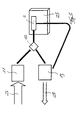
- FIG. 1 shows the essential components of the method, wherein the cycle-dependent temperature control of the tool 1 of an injection molding machine 25 is specifically heated within at least one first cycle section A and selectively cooled within at least one second cycle section B, for which purpose heating elements arranged in the tool 1. / Cooling channels of at least one form of the heating or cooling medium 2 is flowed through.
- a liquid vapor held in the wet steam area is used both as a cooling medium and as a heating medium 2, the liquid vapor being subjected to high pressure during the heating phase A of the tool 1 and low pressure during a cooling phase B of the tool 1.
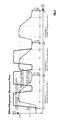
- Drawing Figure 6 shows the Ts diagram for water.
- the cycle of temperature control of the injection molding or thermoforming tool first shown. It can be seen that in the tool 1 during the heating phase A of the tool 1, a condensation of the medium 2 within the wet steam area and during the cooling phase B of the tool 1, an evaporation of the medium within the wet steam area. Furthermore, it is apparent from the drawing figure 6 that at the starting point 3 of the heating of the liquid vapor, a pressure increase of a pressure below 1 bar, namely 0.5 bar is carried out to a pressure above 1 bar, so that at the target point 4 of the heating C of the liquid vapor approx 15 bar.
- the pressure of the liquid vapor from the starting point 5 of the cooling D of the liquid vapor to the target point 6 for cooling D of the liquid vapor of the pressure of 15 to 0.5 bar is lowered to its cooling.
- the temperature of the medium 2 on the input and output sides 7, 8 of the heating / cooling channels is maintained at a substantially equal value. This can be reconstructed, in particular, on the isothermal lines 9, 10 of the heating and cooling phase A, B of the tool 1 running parallel to the X-axis. This means that during the heating A of the tool 1 (condensation phase), the temperature of the liquid vapor is kept substantially constant. This also applies to the cooling phase B (evaporation phase) of the liquid vapor.
- the cycle proceeds on a specific entropy within the Ts-diagram, during the heating process A from the dry side to the wet side on an isotherm 9 higher temperature takes place and the cooling process B to an isotherm 10 low temperature from the wet to the dry side.
- the temperature of the liquid vapor is between 180 and 300 ° C, in the illustrated Ts-diagram the heating isotherm 9 is at a temperature of about 180 ° C.
- the temperature of the liquid vapor is kept at less than 100 ° C, in the illustrated embodiment, the cooling isotherm 10 runs to a value of about 80 C.
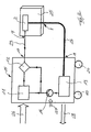
- This device comprises a steam generator 11, in which the cooling / heating medium 2 is evaporated, so that the cooling / heating medium 2 is in the wet steam area.
- This present as liquid vapor cooling / heating medium 2 is supplied via a control valve 12 via the pressure port outlet 17, the supply line 23 and the input side 7 of the injection molding or thermoforming mold 1 of the injection molding machine 25.
- the cooling / heating medium 2 is fed to a recooling element 13, in which it is cooled down.
- the cooling / heating medium 2 is again fed via the vacuum pump 14 to the steam generator 11 and / or the control valve 12 for renewed evaporation or supply to the injection molding or thermoforming tool 1.
- the steam generator 11, the vacuum pump 14, the control valve 12 and the re-cooling element 13 in this case form an assembly 15, which - as shown - on a base body 16 which forms, for example, a mobile unit movable, are arranged.
- This mobile main body unit 16 is operatively connected via pressure connections 17, 18 with the input and output terminals 7, 8 of the tool 1 of the injection molding machine, wherein for this purpose a feed and discharge line 23, 24 is provided for each.
- the base body 16 is enclosed with a housing at least partially surrounding the housing 19 and on its underside with rollers 20th provided, so that the assembly 15 is easily transportable to the place of use.
- an expander 22 connected to a generator 21 is arranged between the tool 1 and the recooling element 13.
- energy (arrows 26, 27) is supplied to the steam generator and the vacuum pump 14 to the overall system for generating steam and for conveying the cooling / heating medium 2.
- the expander 22 which lowers the residual pressure of the output side of the injection molding or thermoforming mold 1 discharged cooling / heating medium 2 and generates by driving the generator 21 thereby electrical energy.
- FIG. 4 is the flow chart of the temperature profile within an injection molding cycle according to the prior art ( FIG. 4 ) and the method according to the invention ( FIG. 5 ).
- the upper limit of the prior art for the temperature control is about 150 ° C, wherein the inventive method, in particular by the present in wet steam form medium 2, a higher temperature can be achieved.
- the cycle duration (X-axis) can be greatly reduced, so that within a double cycle according to the prior art three tempering cycles can be realized by the method according to the invention.
- the temperature gradients 30, 30 ', 30 "of the method according to the invention run steeper than the temperature gradients 31, 31', 31" of the prior art.
Landscapes
- Engineering & Computer Science (AREA)
- Mechanical Engineering (AREA)
- Physics & Mathematics (AREA)
- Health & Medical Sciences (AREA)
- Oral & Maxillofacial Surgery (AREA)
- Thermal Sciences (AREA)
- Manufacturing & Machinery (AREA)
- Moulds For Moulding Plastics Or The Like (AREA)
- Injection Moulding Of Plastics Or The Like (AREA)
Applications Claiming Priority (1)
| Application Number | Priority Date | Filing Date | Title |
|---|---|---|---|
| DE200810062433 DE102008062433B3 (de) | 2008-12-17 | 2008-12-17 | Verfahren zur zyklusabhängigen Temperierung eines Spritzgieß- oder Thermoformwerkzeuges |
Publications (1)
| Publication Number | Publication Date |
|---|---|
| EP2199058A1 true EP2199058A1 (fr) | 2010-06-23 |
Family
ID=41820274
Family Applications (1)
| Application Number | Title | Priority Date | Filing Date |
|---|---|---|---|
| EP09013329A Withdrawn EP2199058A1 (fr) | 2008-12-17 | 2009-10-22 | Procédé d'équilibrage des températures en fonction de cycles d'un outil de moulage par injection ou de thermoformage |
Country Status (2)
| Country | Link |
|---|---|
| EP (1) | EP2199058A1 (fr) |
| DE (1) | DE102008062433B3 (fr) |
Cited By (3)
| Publication number | Priority date | Publication date | Assignee | Title |
|---|---|---|---|---|
| DE202014003102U1 (de) | 2014-04-13 | 2015-07-14 | Fuchs Gmbh & Co. Kg | Im Spritzgussverfahren hergestelltes Kunststoffformteil |
| EP2930003A1 (fr) | 2014-04-13 | 2015-10-14 | Fuchs Kunststofftechnik GmbH | Pièce de formage en plastique fabriquée selon un procédé de moulage par injection |
| CN107824770A (zh) * | 2017-11-02 | 2018-03-23 | 苏州岚山机械科技有限公司 | 一种模具加热的方法 |
Families Citing this family (4)
| Publication number | Priority date | Publication date | Assignee | Title |
|---|---|---|---|---|
| DE102011078167B4 (de) | 2011-06-28 | 2014-03-13 | Joachim Hannebaum | Verfahren zur Temperierung eines Spritzgießwerkzeugs |
| EP2796268A1 (fr) * | 2013-04-24 | 2014-10-29 | Robamat Automatisierungstechnik GmbH | Dispositif et procédé destinés à la thermorégulation d'un moule à outil |
| DE102013112426B4 (de) | 2013-11-12 | 2018-08-23 | Gerresheimer Regensburg Gmbh | Verfahren zum Herstellen eines hohlförmigen Spritzgussteils aus einem thermoplastischen Kunststoff |
| EP3524403A1 (fr) * | 2018-02-13 | 2019-08-14 | G. A. Röders GmbH & Co. KG Druck- & Spritzguss | Dispositif et procédé de refroidissement d'un moule de coulée |
Citations (4)
| Publication number | Priority date | Publication date | Assignee | Title |
|---|---|---|---|---|
| JP2002316341A (ja) * | 2001-04-23 | 2002-10-29 | Mitsui Chemicals Inc | 射出成形用金型の温度調節方法 |
| DE102005036437B3 (de) | 2005-08-03 | 2006-12-21 | Technotrans Ag | Verfahren zum Temperieren von Kunststoff-Spritzgießwerkzeugen |
| WO2007095515A2 (fr) * | 2006-02-13 | 2007-08-23 | Johnson Kenneth E | Procédé et appareil de régulation de température de moules, de matrices et de cylindres d'injection à l'aide d'un milieu fluidique |
| JP2007290279A (ja) * | 2006-04-26 | 2007-11-08 | Tokyo Institute Of Technology | 金型温度制御方法および金型温度制御装置 |
Family Cites Families (1)
| Publication number | Priority date | Publication date | Assignee | Title |
|---|---|---|---|---|
| DE102007047617B3 (de) * | 2007-10-04 | 2009-04-30 | Werkzeugbau Siegfried Hofmann Gmbh | Spritzgießform zum Einsatz in einer Spritzgießvorrichtung |
-
2008
- 2008-12-17 DE DE200810062433 patent/DE102008062433B3/de not_active Expired - Fee Related
-
2009
- 2009-10-22 EP EP09013329A patent/EP2199058A1/fr not_active Withdrawn
Patent Citations (4)
| Publication number | Priority date | Publication date | Assignee | Title |
|---|---|---|---|---|
| JP2002316341A (ja) * | 2001-04-23 | 2002-10-29 | Mitsui Chemicals Inc | 射出成形用金型の温度調節方法 |
| DE102005036437B3 (de) | 2005-08-03 | 2006-12-21 | Technotrans Ag | Verfahren zum Temperieren von Kunststoff-Spritzgießwerkzeugen |
| WO2007095515A2 (fr) * | 2006-02-13 | 2007-08-23 | Johnson Kenneth E | Procédé et appareil de régulation de température de moules, de matrices et de cylindres d'injection à l'aide d'un milieu fluidique |
| JP2007290279A (ja) * | 2006-04-26 | 2007-11-08 | Tokyo Institute Of Technology | 金型温度制御方法および金型温度制御装置 |
Non-Patent Citations (1)
| Title |
|---|
| DATABASE WPI Week 200322, Derwent World Patents Index; AN 2003-224512 * |
Cited By (4)
| Publication number | Priority date | Publication date | Assignee | Title |
|---|---|---|---|---|
| DE202014003102U1 (de) | 2014-04-13 | 2015-07-14 | Fuchs Gmbh & Co. Kg | Im Spritzgussverfahren hergestelltes Kunststoffformteil |
| EP2930003A1 (fr) | 2014-04-13 | 2015-10-14 | Fuchs Kunststofftechnik GmbH | Pièce de formage en plastique fabriquée selon un procédé de moulage par injection |
| DE102014005366A1 (de) | 2014-04-13 | 2015-10-15 | Fuchs Gmbh & Co. Kg | Im Spritzgussverfahren hergestelltes Kunststoffformteil |
| CN107824770A (zh) * | 2017-11-02 | 2018-03-23 | 苏州岚山机械科技有限公司 | 一种模具加热的方法 |
Also Published As
| Publication number | Publication date |
|---|---|
| DE102008062433B3 (de) | 2010-05-06 |
Similar Documents
| Publication | Publication Date | Title |
|---|---|---|
| EP2199058A1 (fr) | Procédé d'équilibrage des températures en fonction de cycles d'un outil de moulage par injection ou de thermoformage | |
| DE2810191C3 (de) | Verfahren und Vorrichtung zum Wärmeentzug aus mindestens einem strömenden Wärmeträgermedium | |
| EP3240945B1 (fr) | Centrale d'accumulation d'air comprimé et procédé pour faire fonctionner une centrale d'accumulation d'air comprimé | |
| DE102010011556A1 (de) | Vorrichtung zur Brennstoffversorgung | |
| DE102011119977A1 (de) | Vorrichtung und Verfahren zur Nutzung der Abwärme einer Brennkraftmaschine, insbesondere zur Nutzung der Abwärme eines Fahrzeugmotors | |
| DE102010033124A1 (de) | Brennkraftmaschine mit einer Wärmerückgewinnungsvorrichtung und Verfahren zum Betrieb einer Brennkraftmaschine | |
| EP2669389A1 (fr) | Procédé et agencement pour récupérer de l'énergie thermique lors du traitement thermique d'une bande d'acier enroulée à froid dans un four de recuit à cloche | |
| DE102007043373A1 (de) | Verdampfer für eine Dampfkreisprozessvorrichtung | |
| EP3139108B1 (fr) | Dispositif de stockage et procede de stockage temporaire d'energie electrique en energie thermique | |
| DE102012000986B3 (de) | Hydraulikeinrichtung mit einer Temperiereinrichtung | |
| EP2835317A1 (fr) | Procédé et dispositif de rétrécissement de matériau sur un article et/ou sur une composition d'articles | |
| DE2808139A1 (de) | Verfahren zum temperieren von formen, insbesondere druckgiess-, spritzguss- o.dgl. formen und vorrichtung zur durchfuehrung des verfahrens | |
| DE102013101648A1 (de) | Verfahren und Vorrichtung zur Speicherung und Übertragung von thermischer Energie | |
| DE102013017330A1 (de) | Verfahren und Vorrichtung zur Vorerwärmung eines pumpfähigen Lebensmittelprodukts in einer Heißabfüllanlage mit einer Wärmepumpe | |
| DE102012011167A1 (de) | Rotationskolbenvorrichtung mit Flashverdampfung | |
| DE102012011909A1 (de) | Vorrichtung und Verfahren zum Umtemperieren von Objekten | |
| DE102015101214A1 (de) | Energiespeichervorrichtung und Verfahren zur Speicherung und/oder Bereitstellung von Energie | |
| DE102010051047A1 (de) | Verfahren zum Temperieren eines Formwerkzeugs | |
| AT524819B1 (de) | Wärmekopplungsvorrichtung für ein Brennstoffzellensystem | |
| DE2802335A1 (de) | Verfahren zum temperieren von formen, insbesondere druckgiess-, spritzguss- o.dgl. formen und vorrichtung zur durchfuehrung des verfahrens | |
| DE903818C (de) | Verfahren zum Betriebe von Dampfkraftmaschinen | |
| DE10301376A1 (de) | Vorrichtung zur thermischen Entkeimung von Flüssigkeiten | |
| DE102008045448A1 (de) | Bereitstellen von Kohlendioxid | |
| DE102014201751A1 (de) | Anlage zur Kraftwärmekopplung und Verfahren zum Betreiben einer solchen Anlage | |
| DE202019105454U1 (de) | Kunststoffurformwerkzeug |
Legal Events
| Date | Code | Title | Description |
|---|---|---|---|
| PUAI | Public reference made under article 153(3) epc to a published international application that has entered the european phase |
Free format text: ORIGINAL CODE: 0009012 |
|
| AK | Designated contracting states |
Kind code of ref document: A1 Designated state(s): AT BE BG CH CY CZ DE DK EE ES FI FR GB GR HR HU IE IS IT LI LT LU LV MC MK MT NL NO PL PT RO SE SI SK SM TR |
|
| AX | Request for extension of the european patent |
Extension state: AL BA RS |
|
| STAA | Information on the status of an ep patent application or granted ep patent |
Free format text: STATUS: THE APPLICATION IS DEEMED TO BE WITHDRAWN |
|
| 18D | Application deemed to be withdrawn |
Effective date: 20101224 |