EP2199014B1 - Vorrichtung zur Vermeidung von Schäden infolge von elektrischen Strömen an einem Werkzeug einer Werkzeugmaschine - Google Patents
Vorrichtung zur Vermeidung von Schäden infolge von elektrischen Strömen an einem Werkzeug einer Werkzeugmaschine Download PDFInfo
- Publication number
- EP2199014B1 EP2199014B1 EP08105986A EP08105986A EP2199014B1 EP 2199014 B1 EP2199014 B1 EP 2199014B1 EP 08105986 A EP08105986 A EP 08105986A EP 08105986 A EP08105986 A EP 08105986A EP 2199014 B1 EP2199014 B1 EP 2199014B1
- Authority
- EP
- European Patent Office
- Prior art keywords
- workpiece
- tool
- insulating
- clamping apparatus
- machine tool
- Prior art date
- Legal status (The legal status is an assumption and is not a legal conclusion. Google has not performed a legal analysis and makes no representation as to the accuracy of the status listed.)
- Not-in-force
Links
- 239000000919 ceramic Substances 0.000 claims abstract description 4
- 229910052594 sapphire Inorganic materials 0.000 claims description 4
- 239000010980 sapphire Substances 0.000 claims description 4
- 239000011810 insulating material Substances 0.000 claims description 2
- 239000012774 insulation material Substances 0.000 abstract 1
- 239000012212 insulator Substances 0.000 description 3
- 238000009413 insulation Methods 0.000 description 2
- 230000015556 catabolic process Effects 0.000 description 1
- 238000010292 electrical insulation Methods 0.000 description 1
- 230000003628 erosive effect Effects 0.000 description 1
- 238000002955 isolation Methods 0.000 description 1
- 239000000463 material Substances 0.000 description 1
- 238000000034 method Methods 0.000 description 1
- 238000003801 milling Methods 0.000 description 1
- 238000000926 separation method Methods 0.000 description 1
Images
Classifications
-
- B—PERFORMING OPERATIONS; TRANSPORTING
- B23—MACHINE TOOLS; METAL-WORKING NOT OTHERWISE PROVIDED FOR
- B23Q—DETAILS, COMPONENTS, OR ACCESSORIES FOR MACHINE TOOLS, e.g. ARRANGEMENTS FOR COPYING OR CONTROLLING; MACHINE TOOLS IN GENERAL CHARACTERISED BY THE CONSTRUCTION OF PARTICULAR DETAILS OR COMPONENTS; COMBINATIONS OR ASSOCIATIONS OF METAL-WORKING MACHINES, NOT DIRECTED TO A PARTICULAR RESULT
- B23Q11/00—Accessories fitted to machine tools for keeping tools or parts of the machine in good working condition or for cooling work; Safety devices specially combined with or arranged in, or specially adapted for use in connection with, machine tools
-
- B—PERFORMING OPERATIONS; TRANSPORTING
- B23—MACHINE TOOLS; METAL-WORKING NOT OTHERWISE PROVIDED FOR
- B23B—TURNING; BORING
- B23B31/00—Chucks; Expansion mandrels; Adaptations thereof for remote control
- B23B31/02—Chucks
- B23B31/10—Chucks characterised by the retaining or gripping devices or their immediate operating means
- B23B31/12—Chucks with simultaneously-acting jaws, whether or not also individually adjustable
- B23B31/16—Chucks with simultaneously-acting jaws, whether or not also individually adjustable moving radially
- B23B31/1627—Details of the jaws
- B23B31/16275—Form of the jaws
-
- B—PERFORMING OPERATIONS; TRANSPORTING
- B23—MACHINE TOOLS; METAL-WORKING NOT OTHERWISE PROVIDED FOR
- B23B—TURNING; BORING
- B23B2226/00—Materials of tools or workpieces not comprising a metal
- B23B2226/69—Sapphire
Definitions
- the invention relates to a workpiece clamping device for avoiding damage due to electrical currents on a tool of a machine tool.
- the publication DE 27 17 593 A1 discloses an arrangement for suppressing RF currents in bearings of waves. The task is solved by means of an electronic circuit.
- DE 2839246 C2 also an arrangement for suppressing RF currents in bearings and shafts, also solved by a special electronics.
- US 6,227,549 discloses a tool clamping device for interrupting the flow of current between an electrical cable and the operator.
- the object of the invention is to reduce or eliminate the erosion damage to the tools of machine tools as a result of electrical currents.
- the insulating body may consist of at least one cylindrical body of insulating material and be arranged below the clamped in a clamping device workpiece.
- the insulating bodies are arranged on the clamping jaw ends facing the clamped workpiece, wherein the electrical current flow between the clamping jaws and the clamped workpiece is interrupted.
- insulating ceramic pins or insulating sapphire pins may be arranged.
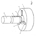
- the FIG. 1 shows a clamping device 1 of a machine tool, not shown.
- two insulating body 3, and 4 are shown schematically, with a cylindrical workpiece 6 is located above.
- the tool used for processing for example a drill or milling cutter, which is located above the workpiece 6, is not shown.
- one or more insulating bodies 3, 4 of different thickness can be provided between the clamped workpiece 6 or the tool.
- the material, such as plastic, ceramic, etc., and the geometry (thickness, height, etc.) must be chosen so that no current can occur due to the breakdown voltage.
- the first insulating body 3 can be omitted if the workpiece is clamped without contact from the bottom of the clamping device 1.
- the second insulating body 4 is used for electrical separation of jaws 2 and 6 workpiece.
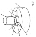
- FIG. 2 Another embodiment is in FIG. 2 shown. Between the workpiece 6 and the clamping device 1, a disc-shaped insulating body 5 is provided.
- insulation pins 8 for example of sapphire, which likewise have suitable electrical insulation, are arranged on the clamping jaw ends 7 facing the workpiece 6.
- the advantages achieved by the invention are in particular that the service life of the machine tool can be significantly shortened.
- at least two workpieces can be machined with a single tool, which is currently not possible in the prior art.
Landscapes
- Engineering & Computer Science (AREA)
- Mechanical Engineering (AREA)
- Electrical Discharge Machining, Electrochemical Machining, And Combined Machining (AREA)
- Gripping On Spindles (AREA)
- Turning (AREA)
- Auxiliary Devices For Machine Tools (AREA)
Description
- Die Erfindung betrifft eine Werkstückspannvorrichtung zur Vermeidung von Schäden infolge von elektrischen Strömen an einem Werkzeug einer Werkzeugmaschine.
- In einer Werkzeugmaschine können unerwünschte elektrische Ströme auftreten, die elektro-erodierende Einflüsse auf die Werkzeuge haben, so dass diese frühzeitig ausgetauscht, gereinigt und neu vermessen werden müssen, welches zu höheren Standzeiten der Maschinen führt.
- Diese Stromschädigungen treten beispielsweise auch an den Lagern elektrischer Maschinen auf.
- Beispielweise ist ein Verfahren und eine Anordnung zur Verhinderung von Lagerströmen bei elektrischen Maschinen in der Druckschrift
DD PS 140 185 - Die Offenlegungsschrift
DE 27 17 593 A1 offenbart eine Anordnung zum Unterdrücken von HF-Strömen in Lagern von Wellen. Die Aufgabe wird mittels einer elektronischen Schaltung gelöst. - Weiterhin zeigt die Patentschrift
DE 2839246 C2 ebenfalls eine Anordnung zum Unterdrücken von HF-Strömen in Lagern und Wellen, auch gelöst durch eine spezielle Elektronik. -
US-6,227,549 offenbart eine Werkzeugspannvorrichtung zum Unterbrechen des Stromflusses zwischen einem elektrischenkabel und dem Bediener. - Die Aufgabe der Erfindung besteht darin, die Erosionsschäden an den Werkzeugen von Werkzeugmaschinen infolge von elektrischen Strömen zu reduzieren oder zu beseitigen.
- Diese Aufgabe wird erfindungsgemäss durch die Vorrichtung nach Anspruch 1 gelöst.
- In vorteilhafter Weise können die Isolierkörper aus mindestens einem zylindrischen Körper aus isolierendem Material bestehen und unterhalb des in einer Spannvorrichtung eingespannten Werkstückes angeordnet sein.
- Weiterhin ist es beispielsweise möglich, dass die Isolierkörper an den zum eingespannten Werkstück weisenden Spannbackenenden angeordnet sind, wobei der elektrische Stromfluss zwischen den Spannbacken und dem eingespannten Werkstück unterbrochen ist.
- In den Spannbackenenden können isolierende Keramikstifte oder isolierende Saphirstifte angeordnet sein.
- Anhand einer Zeichnung wird die Erfindung als mögliches Ausführungsbeispiel dargestellt. Es zeigen
-
Fig. 1 ein isoliertes Werkstück mit zwei Isolationskörpern -
Fig.2 eine Isolationseinrichtung mit isolierten Spannbackenspitzen - Die
Figur 1 zeigt eine Spannvorrichtung 1 einer nicht dargestellten Werkzeugmaschine. Oberhalb der Spannvorrichtung 1 mit den Spannbacken 2 sind zwei Isolierkörper 3, und 4 schematisch dargestellt, wobei sich darüber ein zylindrisches Werkstück 6 befindet. Das zur Bearbeitung dienende Werkzeug, beispielsweise ein Bohrer oder Fräser, welches sich oberhalb des Werkstückes 6 befindet, ist nicht gezeigt. Je nach Anforderungen können ein oder mehrere Isolierkörper 3, 4 unterschiedlicher Dicke zwischen dem eingespannten Werkstück 6 oder dem Werkzeug vorgesehen sein. Der Werkstoff, beispielsweise Kunststoff, Keramik etc., und die Geometrie (Dicke, Höhe, etc.) muss so gewählt sein, dass kein Strom infolge der Durchbruchsspannung auftreten kann. Der erste Isolierkörper 3 kann entfallen, wenn das Werkstück berührungslos vom Boden der Spannvorrichtung 1 eingespannt wird. Der zweite Isolierkörper 4 dient zur elektrischen Trennung von Spannbacken 2 und Werkstück 6. - Ein anderes Ausführungsbeispiel ist in
Figur 2 dargestellt. Zwischen dem Werkstück 6 und der Spannvorrichtung 1 ist ein scheibenförmiger Isolationskörper 5 vorgesehen. - Weiterhin sind an den zum Werkstück 6 gerichteten Spannbackenenden 7 Isolationsstifte 8, beispielsweise aus Saphir angeordnet, die ebenfalls eine geeignete elektrische Isolierung aufweisen.
- Die mit der Erfindung erzielten Vorteile liegen insbesondere darin, dass die Standzeiten der Werkzeugmaschine deutlich verkürzt werden. Insbesondere können beispielsweise mindestens zwei Werkstücke mit einem einzigen Werkzeug bearbeitet werden, was derzeit der Stand der Technik nicht ermöglicht.
-
- 1
- Spannvorrichtung
- 2
- Spannbacken
- 3
- Isolierkörper
- 4
- Isolierkörper
- 5
- Isolierkörper
- 6
- Werkstück
- 7
- Enden der Spannbacken
- 8
- Saphirstifte
Claims (5)
- Werkstück-Spannvorrichtung (1) für Werkzeugmaschinen zur Vermeidung von Schäden infolge von elektrischen Strömen an einem Werkzeug einer Werkzeugmaschine, dadurch gekennzeichnet, dass die Werkstück-Spannvorrichtung (1) Isolierkörper (3, 4, 5, 8) aufweist, die den schädigenden Stromfluss zwischen dem Werkzeug der Werkzeugmaschine und einem Werkstück (6) unterbrechen.
- Werkstück-Spannvorrichtung (1) nach Anspruch 1, dadurch gekennzeichnet, dass die Isolierkörper (3, 4, 5) aus mindestens einem zylindrischen Körper aus isolierendem Material bestehen und unterhalb des in der Werkstück-Spannvorrichtung (1) eingespannten Werkstückes (6) angeordnet sind.
- Werkstück-Spannvorrichtung (1) nach Anspruch 1 oder 2, dadurch gekennzeichnet, dass die Isolierkörper (8) an den zum eingespannten Werkstück weisenden Spannbackenenden (7) angeordnet sind, womit ein elektrischer Stromfluss zwischen den Spannbacken (2) und dem eingespannten Werkstück (6) unterbrochen wird.
- Werkstück-Spannvorrichtung (1) nach Anspruch 1, 2 oder 3. dadurch gekennzeichnet, dass in den Spannbackenenden (7) isolierende Keramikstifte (8) angeordnet sind.
- Werkstück-Spannvorrichtung (1) nach Anspruch 1, 2 oder 3, dadurch gekennzeichnet, dass in den Spannbackenenden (7) isolierende Saphirstifte (8) angeordnet sind
Priority Applications (4)
| Application Number | Priority Date | Filing Date | Title |
|---|---|---|---|
| ES08105986T ES2382683T3 (es) | 2008-12-16 | 2008-12-16 | Dispositivo para la prevención de daños como consecuencia de corrientes eléctricas en una herramienta de una máquina herramienta |
| AT08105986T ATE545476T1 (de) | 2008-12-16 | 2008-12-16 | Vorrichtung zur vermeidung von schäden infolge von elektrischen strömen an einem werkzeug einer werkzeugmaschine |
| EP08105986A EP2199014B1 (de) | 2008-12-16 | 2008-12-16 | Vorrichtung zur Vermeidung von Schäden infolge von elektrischen Strömen an einem Werkzeug einer Werkzeugmaschine |
| JP2009284299A JP5635768B2 (ja) | 2008-12-16 | 2009-12-15 | 電流による工作機械の工具損傷を防止するための加工材締付け装置 |
Applications Claiming Priority (1)
| Application Number | Priority Date | Filing Date | Title |
|---|---|---|---|
| EP08105986A EP2199014B1 (de) | 2008-12-16 | 2008-12-16 | Vorrichtung zur Vermeidung von Schäden infolge von elektrischen Strömen an einem Werkzeug einer Werkzeugmaschine |
Publications (2)
| Publication Number | Publication Date |
|---|---|
| EP2199014A1 EP2199014A1 (de) | 2010-06-23 |
| EP2199014B1 true EP2199014B1 (de) | 2012-02-15 |
Family
ID=40677607
Family Applications (1)
| Application Number | Title | Priority Date | Filing Date |
|---|---|---|---|
| EP08105986A Not-in-force EP2199014B1 (de) | 2008-12-16 | 2008-12-16 | Vorrichtung zur Vermeidung von Schäden infolge von elektrischen Strömen an einem Werkzeug einer Werkzeugmaschine |
Country Status (4)
| Country | Link |
|---|---|
| EP (1) | EP2199014B1 (de) |
| JP (1) | JP5635768B2 (de) |
| AT (1) | ATE545476T1 (de) |
| ES (1) | ES2382683T3 (de) |
Families Citing this family (1)
| Publication number | Priority date | Publication date | Assignee | Title |
|---|---|---|---|---|
| NL2006680C2 (nl) * | 2011-04-28 | 2012-10-30 | Adamas B V | Bedieningsmiddel voor een bewerkingsmachine. |
Family Cites Families (8)
| Publication number | Priority date | Publication date | Assignee | Title |
|---|---|---|---|---|
| FR1462650A (fr) * | 1965-12-31 | 1966-12-16 | Vni Instrument Inst | Dispositif pour la fixation d'outil et de pièce à usiner sur les machines-outils travaillant par enlèvement de métal |
| DE2717593C3 (de) | 1977-04-20 | 1979-10-11 | Siemens Ag, 1000 Berlin Und 8000 Muenchen | Anordnung zum Unterdrücken von HF-Strömen in Lagern von Wellen |
| DE2839246C2 (de) | 1978-09-08 | 1983-01-05 | Siemens AG, 1000 Berlin und 8000 München | Anordnung zum Unterdrücken von HF-Strömen in Lagern von Wellen |
| DD140185A1 (de) | 1978-11-28 | 1980-02-13 | Dietrich Schilling | Verfahren und anordnung zur verhinderung von lagerstroemen bei elektrischen maschinen |
| JP3504318B2 (ja) * | 1994-02-28 | 2004-03-08 | 京セラ株式会社 | 物品把持装置 |
| US6227549B1 (en) * | 2000-02-22 | 2001-05-08 | S-B Power Tool Company | Insulated chuck jaw |
| US6997656B2 (en) * | 2003-07-18 | 2006-02-14 | Bengston Tool + Die Co., Inc. | Device and assembly for holding an object |
| JP4552010B2 (ja) * | 2004-12-06 | 2010-09-29 | 国立大学法人金沢大学 | 鋼の切削方法及び切削装置 |
-
2008
- 2008-12-16 EP EP08105986A patent/EP2199014B1/de not_active Not-in-force
- 2008-12-16 ES ES08105986T patent/ES2382683T3/es active Active
- 2008-12-16 AT AT08105986T patent/ATE545476T1/de active
-
2009
- 2009-12-15 JP JP2009284299A patent/JP5635768B2/ja not_active Expired - Fee Related
Also Published As
| Publication number | Publication date |
|---|---|
| JP5635768B2 (ja) | 2014-12-03 |
| ES2382683T3 (es) | 2012-06-12 |
| JP2010142945A (ja) | 2010-07-01 |
| ATE545476T1 (de) | 2012-03-15 |
| EP2199014A1 (de) | 2010-06-23 |
Similar Documents
| Publication | Publication Date | Title |
|---|---|---|
| EP2069103B1 (de) | Verfahren zum einspannen verformungsempfindlicher werkstücke und spannfutter zur durchführung des verfahrens | |
| EP2298475B1 (de) | Spannfutter zum Spannen und Zentrieren ringförmig ausgebildeter und verformungsempfindlicher Werkstücke | |
| DE3829814C2 (de) | Aufspannvorrichtung und Verfahren zum Festlegen eines Werkstücks | |
| WO2011134903A1 (de) | Turbinenschaufelrohling sowie verfahren und vorrichtung zum bearbeiten eines turbinenschaufelrohlings | |
| DE102009047996B3 (de) | Spannfutter zum Spannen und Zentrieren ringförmig ausgebildeter und verformungsempfindlicher Werkstücke | |
| EP1543915B1 (de) | Kollisionsschutzeinrichtung eines Laserbearbeitungskopfes | |
| EP2226145A2 (de) | Spannvorrichtung | |
| EP0307473A1 (de) | Entladungsanordnung für magneto-pulsierungen bei der behandlung und beim schweissen von metallen | |
| EP2263834B1 (de) | Vorrichtung zum Herausziehen von Einspritzdüsen von Dieselmotoren | |
| EP2199014B1 (de) | Vorrichtung zur Vermeidung von Schäden infolge von elektrischen Strömen an einem Werkzeug einer Werkzeugmaschine | |
| DE1125733B (de) | Vorrichtung zum Melden eines Werkzeugbruches an Dreh- und Hobelmaschinen waehrend des Bearbeitungsvorganges | |
| DE102007025009A1 (de) | Stator einer elektrischen Maschine, elektrische Maschine sowie Elektrowerkzeugmaschine | |
| DE112017005989B4 (de) | Funkenerodierverfahren und funkenerodiervorrichtung | |
| DE102009054425B4 (de) | Abzieheinrichtung zum Abziehen von Elektrodenkappen von Schweißelektroden | |
| DE102011011550B3 (de) | Spannvorrichtungen mit Werkstück-Auflagekontrolle | |
| DE102016225503A1 (de) | Stator für eine elektrische Rotationsmaschine | |
| DE102007025196B4 (de) | Magnetische Spannvorrichtung | |
| EP2644315A1 (de) | Autarke elektrohydraulische Werkstückspannvorrichtung | |
| CH683971A5 (de) | Vorrichtung zur elektro-erosiven Bearbeitung mit mehrfachen Werkzeugelektroden. | |
| DE102007025010B4 (de) | Stator einer elektrischen Maschine, elektrische Maschine sowie Elektrowerkzeugmaschine | |
| DE102011011415B4 (de) | Überprüfung eines Entgratungswerkzeuges | |
| DE102013001765B4 (de) | Elektrodenfräswerkzeuge, Elektrodenfräsvorrichtung und Verfahren zum Nachbearbeiten von verschlissenen Punktschweißelektroden | |
| DE102015214262A1 (de) | Verfahren und Vorrichtung zum Schleiferodieren von Werkstücken | |
| EP3291383B1 (de) | Schalteinrichtung zur kontaktierung einer elektrischen baugruppe | |
| EP1521349A1 (de) | Elektrische Maschine |
Legal Events
| Date | Code | Title | Description |
|---|---|---|---|
| PUAI | Public reference made under article 153(3) epc to a published international application that has entered the european phase |
Free format text: ORIGINAL CODE: 0009012 |
|
| AK | Designated contracting states |
Kind code of ref document: A1 Designated state(s): AT BE BG CH CY CZ DE DK EE ES FI FR GB GR HR HU IE IS IT LI LT LU LV MC MT NL NO PL PT RO SE SI SK TR |
|
| AX | Request for extension of the european patent |
Extension state: AL BA MK RS |
|
| 17P | Request for examination filed |
Effective date: 20100804 |
|
| 17Q | First examination report despatched |
Effective date: 20100827 |
|
| AKX | Designation fees paid |
Designated state(s): AT BE BG CH CY CZ DE DK EE ES FI FR GB GR HR HU IE IS IT LI LT LU LV MC MT NL NO PL PT RO SE SI SK TR |
|
| REG | Reference to a national code |
Ref country code: DE Ref legal event code: R079 Ref document number: 502008006405 Country of ref document: DE Free format text: PREVIOUS MAIN CLASS: B23Q0011000000 Ipc: B23B0031160000 |
|
| GRAP | Despatch of communication of intention to grant a patent |
Free format text: ORIGINAL CODE: EPIDOSNIGR1 |
|
| RIC1 | Information provided on ipc code assigned before grant |
Ipc: B23Q 11/00 20060101ALI20110804BHEP Ipc: B23B 31/00 20060101ALI20110804BHEP Ipc: B23B 31/16 20060101AFI20110804BHEP |
|
| GRAS | Grant fee paid |
Free format text: ORIGINAL CODE: EPIDOSNIGR3 |
|
| GRAA | (expected) grant |
Free format text: ORIGINAL CODE: 0009210 |
|
| AK | Designated contracting states |
Kind code of ref document: B1 Designated state(s): AT BE BG CH CY CZ DE DK EE ES FI FR GB GR HR HU IE IS IT LI LT LU LV MC MT NL NO PL PT RO SE SI SK TR |
|
| REG | Reference to a national code |
Ref country code: GB Ref legal event code: FG4D Free format text: NOT ENGLISH Ref country code: CH Ref legal event code: EP Ref country code: CH Ref legal event code: NV Representative=s name: GEORG FISCHER AG |
|
| REG | Reference to a national code |
Ref country code: IE Ref legal event code: FG4D Free format text: LANGUAGE OF EP DOCUMENT: GERMAN |
|
| REG | Reference to a national code |
Ref country code: AT Ref legal event code: REF Ref document number: 545476 Country of ref document: AT Kind code of ref document: T Effective date: 20120315 |
|
| REG | Reference to a national code |
Ref country code: DE Ref legal event code: R096 Ref document number: 502008006405 Country of ref document: DE Effective date: 20120412 |
|
| REG | Reference to a national code |
Ref country code: ES Ref legal event code: FG2A Ref document number: 2382683 Country of ref document: ES Kind code of ref document: T3 Effective date: 20120612 |
|
| REG | Reference to a national code |
Ref country code: NL Ref legal event code: VDEP Effective date: 20120215 |
|
| LTIE | Lt: invalidation of european patent or patent extension |
Effective date: 20120215 |
|
| PG25 | Lapsed in a contracting state [announced via postgrant information from national office to epo] |
Ref country code: NO Free format text: LAPSE BECAUSE OF FAILURE TO SUBMIT A TRANSLATION OF THE DESCRIPTION OR TO PAY THE FEE WITHIN THE PRESCRIBED TIME-LIMIT Effective date: 20120515 Ref country code: IS Free format text: LAPSE BECAUSE OF FAILURE TO SUBMIT A TRANSLATION OF THE DESCRIPTION OR TO PAY THE FEE WITHIN THE PRESCRIBED TIME-LIMIT Effective date: 20120615 Ref country code: NL Free format text: LAPSE BECAUSE OF FAILURE TO SUBMIT A TRANSLATION OF THE DESCRIPTION OR TO PAY THE FEE WITHIN THE PRESCRIBED TIME-LIMIT Effective date: 20120215 Ref country code: HR Free format text: LAPSE BECAUSE OF FAILURE TO SUBMIT A TRANSLATION OF THE DESCRIPTION OR TO PAY THE FEE WITHIN THE PRESCRIBED TIME-LIMIT Effective date: 20120215 Ref country code: LT Free format text: LAPSE BECAUSE OF FAILURE TO SUBMIT A TRANSLATION OF THE DESCRIPTION OR TO PAY THE FEE WITHIN THE PRESCRIBED TIME-LIMIT Effective date: 20120215 |
|
| PG25 | Lapsed in a contracting state [announced via postgrant information from national office to epo] |
Ref country code: PT Free format text: LAPSE BECAUSE OF FAILURE TO SUBMIT A TRANSLATION OF THE DESCRIPTION OR TO PAY THE FEE WITHIN THE PRESCRIBED TIME-LIMIT Effective date: 20120615 Ref country code: GR Free format text: LAPSE BECAUSE OF FAILURE TO SUBMIT A TRANSLATION OF THE DESCRIPTION OR TO PAY THE FEE WITHIN THE PRESCRIBED TIME-LIMIT Effective date: 20120516 Ref country code: PL Free format text: LAPSE BECAUSE OF FAILURE TO SUBMIT A TRANSLATION OF THE DESCRIPTION OR TO PAY THE FEE WITHIN THE PRESCRIBED TIME-LIMIT Effective date: 20120215 Ref country code: LV Free format text: LAPSE BECAUSE OF FAILURE TO SUBMIT A TRANSLATION OF THE DESCRIPTION OR TO PAY THE FEE WITHIN THE PRESCRIBED TIME-LIMIT Effective date: 20120215 Ref country code: FI Free format text: LAPSE BECAUSE OF FAILURE TO SUBMIT A TRANSLATION OF THE DESCRIPTION OR TO PAY THE FEE WITHIN THE PRESCRIBED TIME-LIMIT Effective date: 20120215 |
|
| REG | Reference to a national code |
Ref country code: IE Ref legal event code: FD4D |
|
| PG25 | Lapsed in a contracting state [announced via postgrant information from national office to epo] |
Ref country code: CY Free format text: LAPSE BECAUSE OF FAILURE TO SUBMIT A TRANSLATION OF THE DESCRIPTION OR TO PAY THE FEE WITHIN THE PRESCRIBED TIME-LIMIT Effective date: 20120215 |
|
| PG25 | Lapsed in a contracting state [announced via postgrant information from national office to epo] |
Ref country code: DK Free format text: LAPSE BECAUSE OF FAILURE TO SUBMIT A TRANSLATION OF THE DESCRIPTION OR TO PAY THE FEE WITHIN THE PRESCRIBED TIME-LIMIT Effective date: 20120215 Ref country code: SI Free format text: LAPSE BECAUSE OF FAILURE TO SUBMIT A TRANSLATION OF THE DESCRIPTION OR TO PAY THE FEE WITHIN THE PRESCRIBED TIME-LIMIT Effective date: 20120215 Ref country code: EE Free format text: LAPSE BECAUSE OF FAILURE TO SUBMIT A TRANSLATION OF THE DESCRIPTION OR TO PAY THE FEE WITHIN THE PRESCRIBED TIME-LIMIT Effective date: 20120215 Ref country code: CZ Free format text: LAPSE BECAUSE OF FAILURE TO SUBMIT A TRANSLATION OF THE DESCRIPTION OR TO PAY THE FEE WITHIN THE PRESCRIBED TIME-LIMIT Effective date: 20120215 Ref country code: RO Free format text: LAPSE BECAUSE OF FAILURE TO SUBMIT A TRANSLATION OF THE DESCRIPTION OR TO PAY THE FEE WITHIN THE PRESCRIBED TIME-LIMIT Effective date: 20120215 Ref country code: IE Free format text: LAPSE BECAUSE OF FAILURE TO SUBMIT A TRANSLATION OF THE DESCRIPTION OR TO PAY THE FEE WITHIN THE PRESCRIBED TIME-LIMIT Effective date: 20120215 Ref country code: SE Free format text: LAPSE BECAUSE OF FAILURE TO SUBMIT A TRANSLATION OF THE DESCRIPTION OR TO PAY THE FEE WITHIN THE PRESCRIBED TIME-LIMIT Effective date: 20120215 |
|
| PG25 | Lapsed in a contracting state [announced via postgrant information from national office to epo] |
Ref country code: SK Free format text: LAPSE BECAUSE OF FAILURE TO SUBMIT A TRANSLATION OF THE DESCRIPTION OR TO PAY THE FEE WITHIN THE PRESCRIBED TIME-LIMIT Effective date: 20120215 |
|
| PLBE | No opposition filed within time limit |
Free format text: ORIGINAL CODE: 0009261 |
|
| STAA | Information on the status of an ep patent application or granted ep patent |
Free format text: STATUS: NO OPPOSITION FILED WITHIN TIME LIMIT |
|
| 26N | No opposition filed |
Effective date: 20121116 |
|
| REG | Reference to a national code |
Ref country code: DE Ref legal event code: R097 Ref document number: 502008006405 Country of ref document: DE Effective date: 20121116 |
|
| BERE | Be: lapsed |
Owner name: MIKRON AGIE CHARMILLES AG Effective date: 20121231 |
|
| PG25 | Lapsed in a contracting state [announced via postgrant information from national office to epo] |
Ref country code: MC Free format text: LAPSE BECAUSE OF NON-PAYMENT OF DUE FEES Effective date: 20121231 Ref country code: BG Free format text: LAPSE BECAUSE OF FAILURE TO SUBMIT A TRANSLATION OF THE DESCRIPTION OR TO PAY THE FEE WITHIN THE PRESCRIBED TIME-LIMIT Effective date: 20120515 |
|
| PG25 | Lapsed in a contracting state [announced via postgrant information from national office to epo] |
Ref country code: BE Free format text: LAPSE BECAUSE OF NON-PAYMENT OF DUE FEES Effective date: 20121231 |
|
| PG25 | Lapsed in a contracting state [announced via postgrant information from national office to epo] |
Ref country code: MT Free format text: LAPSE BECAUSE OF FAILURE TO SUBMIT A TRANSLATION OF THE DESCRIPTION OR TO PAY THE FEE WITHIN THE PRESCRIBED TIME-LIMIT Effective date: 20120215 |
|
| PG25 | Lapsed in a contracting state [announced via postgrant information from national office to epo] |
Ref country code: TR Free format text: LAPSE BECAUSE OF FAILURE TO SUBMIT A TRANSLATION OF THE DESCRIPTION OR TO PAY THE FEE WITHIN THE PRESCRIBED TIME-LIMIT Effective date: 20120215 |
|
| PG25 | Lapsed in a contracting state [announced via postgrant information from national office to epo] |
Ref country code: LU Free format text: LAPSE BECAUSE OF NON-PAYMENT OF DUE FEES Effective date: 20121216 |
|
| PG25 | Lapsed in a contracting state [announced via postgrant information from national office to epo] |
Ref country code: HU Free format text: LAPSE BECAUSE OF FAILURE TO SUBMIT A TRANSLATION OF THE DESCRIPTION OR TO PAY THE FEE WITHIN THE PRESCRIBED TIME-LIMIT Effective date: 20081216 |
|
| PGFP | Annual fee paid to national office [announced via postgrant information from national office to epo] |
Ref country code: ES Payment date: 20141226 Year of fee payment: 7 |
|
| REG | Reference to a national code |
Ref country code: AT Ref legal event code: MM01 Ref document number: 545476 Country of ref document: AT Kind code of ref document: T Effective date: 20131216 |
|
| PG25 | Lapsed in a contracting state [announced via postgrant information from national office to epo] |
Ref country code: AT Free format text: LAPSE BECAUSE OF NON-PAYMENT OF DUE FEES Effective date: 20131216 |
|
| REG | Reference to a national code |
Ref country code: FR Ref legal event code: PLFP Year of fee payment: 8 |
|
| PGFP | Annual fee paid to national office [announced via postgrant information from national office to epo] |
Ref country code: GB Payment date: 20151221 Year of fee payment: 8 Ref country code: DE Payment date: 20151210 Year of fee payment: 8 Ref country code: CH Payment date: 20151221 Year of fee payment: 8 |
|
| PGFP | Annual fee paid to national office [announced via postgrant information from national office to epo] |
Ref country code: FR Payment date: 20151221 Year of fee payment: 8 |
|
| PGFP | Annual fee paid to national office [announced via postgrant information from national office to epo] |
Ref country code: IT Payment date: 20151228 Year of fee payment: 8 |
|
| PG25 | Lapsed in a contracting state [announced via postgrant information from national office to epo] |
Ref country code: ES Free format text: LAPSE BECAUSE OF NON-PAYMENT OF DUE FEES Effective date: 20151217 |
|
| REG | Reference to a national code |
Ref country code: DE Ref legal event code: R119 Ref document number: 502008006405 Country of ref document: DE |
|
| REG | Reference to a national code |
Ref country code: CH Ref legal event code: PL |
|
| GBPC | Gb: european patent ceased through non-payment of renewal fee |
Effective date: 20161216 |
|
| REG | Reference to a national code |
Ref country code: FR Ref legal event code: ST Effective date: 20170831 |
|
| PG25 | Lapsed in a contracting state [announced via postgrant information from national office to epo] |
Ref country code: IT Free format text: LAPSE BECAUSE OF NON-PAYMENT OF DUE FEES Effective date: 20161216 Ref country code: LI Free format text: LAPSE BECAUSE OF NON-PAYMENT OF DUE FEES Effective date: 20161231 Ref country code: CH Free format text: LAPSE BECAUSE OF NON-PAYMENT OF DUE FEES Effective date: 20161231 Ref country code: FR Free format text: LAPSE BECAUSE OF NON-PAYMENT OF DUE FEES Effective date: 20170102 |
|
| PG25 | Lapsed in a contracting state [announced via postgrant information from national office to epo] |
Ref country code: GB Free format text: LAPSE BECAUSE OF NON-PAYMENT OF DUE FEES Effective date: 20161216 Ref country code: DE Free format text: LAPSE BECAUSE OF NON-PAYMENT OF DUE FEES Effective date: 20170701 |