EP2198530B1 - Verfahren und vorrichtung für einen selbstabstimmenden vorcodierer - Google Patents
Verfahren und vorrichtung für einen selbstabstimmenden vorcodierer Download PDFInfo
- Publication number
- EP2198530B1 EP2198530B1 EP08795562.1A EP08795562A EP2198530B1 EP 2198530 B1 EP2198530 B1 EP 2198530B1 EP 08795562 A EP08795562 A EP 08795562A EP 2198530 B1 EP2198530 B1 EP 2198530B1
- Authority
- EP
- European Patent Office
- Prior art keywords
- data signals
- crosstalk
- measures
- estimated measures
- transmitter
- Prior art date
- Legal status (The legal status is an assumption and is not a legal conclusion. Google has not performed a legal analysis and makes no representation as to the accuracy of the status listed.)
- Not-in-force
Links
- 238000000034 method Methods 0.000 title claims description 49
- 238000004891 communication Methods 0.000 claims description 43
- 239000011159 matrix material Substances 0.000 claims description 42
- 238000005259 measurement Methods 0.000 claims description 12
- 230000005540 biological transmission Effects 0.000 claims description 9
- 230000008569 process Effects 0.000 claims description 5
- 239000013598 vector Substances 0.000 description 9
- 230000006978 adaptation Effects 0.000 description 7
- 230000000875 corresponding effect Effects 0.000 description 5
- 230000003044 adaptive effect Effects 0.000 description 4
- 238000013459 approach Methods 0.000 description 4
- 230000001413 cellular effect Effects 0.000 description 3
- 230000008859 change Effects 0.000 description 3
- 230000000694 effects Effects 0.000 description 3
- 230000006870 function Effects 0.000 description 3
- 230000015654 memory Effects 0.000 description 3
- 230000003094 perturbing effect Effects 0.000 description 3
- 238000012545 processing Methods 0.000 description 3
- 230000004044 response Effects 0.000 description 3
- 230000008901 benefit Effects 0.000 description 2
- 238000005457 optimization Methods 0.000 description 2
- 230000009467 reduction Effects 0.000 description 2
- 238000013468 resource allocation Methods 0.000 description 2
- 238000001228 spectrum Methods 0.000 description 2
- RYGMFSIKBFXOCR-UHFFFAOYSA-N Copper Chemical compound [Cu] RYGMFSIKBFXOCR-UHFFFAOYSA-N 0.000 description 1
- 230000009471 action Effects 0.000 description 1
- 230000009194 climbing Effects 0.000 description 1
- 238000012937 correction Methods 0.000 description 1
- 230000002596 correlated effect Effects 0.000 description 1
- 238000013461 design Methods 0.000 description 1
- 238000002474 experimental method Methods 0.000 description 1
- 238000012423 maintenance Methods 0.000 description 1
- 238000007726 management method Methods 0.000 description 1
- 238000000691 measurement method Methods 0.000 description 1
- 238000012986 modification Methods 0.000 description 1
- 230000004048 modification Effects 0.000 description 1
- ORQBXQOJMQIAOY-UHFFFAOYSA-N nobelium Chemical compound [No] ORQBXQOJMQIAOY-UHFFFAOYSA-N 0.000 description 1
- 238000012887 quadratic function Methods 0.000 description 1
- 238000013139 quantization Methods 0.000 description 1
- 239000007787 solid Substances 0.000 description 1
- 238000012546 transfer Methods 0.000 description 1
Images


Classifications
-
- H—ELECTRICITY
- H04—ELECTRIC COMMUNICATION TECHNIQUE
- H04B—TRANSMISSION
- H04B3/00—Line transmission systems
- H04B3/02—Details
- H04B3/32—Reducing cross-talk, e.g. by compensating
Definitions
- the present invention relates generally to communication systems, and more particularly to techniques for compensating for crosstalk between communication channels in such systems.
- a communication system may utilize multiple communication channels to communicate signals between transmitters and receivers of the system.
- multiple channels may be used to separate different transmitted data signals from one another, or to provide an increased data rate.
- each of the channels may comprise orthogonal frequency division multiplexed (OFDM) tones or discrete multitone modulation (DMT) tones transmitted over a physical communication link such as twisted-pair copper wire.
- OFDM orthogonal frequency division multiplexed
- DMT discrete multitone modulation
- a transmission on one subscriber line may be detected on other subscriber lines, leading to interference that can degrade the throughput performance of the system.
- a given "victim" channel may experience crosstalk from multiple "disturber” channels, again leading to undesirable interference.
- Patent application EP 1109328 discloses a DSL transmission system with far-end crosstalk (FEXT) compensation. It proposes a canceller circuit for a DMT based DSL transmission system capable of significantly removing the FEXT interference.
- the solution comprises estimating the channel transfer matrix.
- the present invention in one or more illustrative embodiments provides techniques for compensating for crosstalk using adaptation of data signals transmitted over respective channels of a communication system.
- a method comprises the following steps.
- a first set of estimated measures of crosstalk is obtained for at least a selected portion of a plurality of communication channels over which data signals are to be transmitted from a transmitter to at least a selected portion of a plurality of receivers.
- a first set of data signals based on the first set of estimated measures of crosstalk is adapted to generate a first set of adjusted data signals.
- the first set of adjusted data signals is transmitted to corresponding ones of the plurality of receivers.
- a second set of estimated measures of crosstalk is obtained for the selected portion of the plurality of communication channels.
- the steps of adjusting the first set of data signals and the second set of data signals may each further comprise adapting a precoding matrix that comprises elements that are generated from the obtained set of estimated measures of crosstalk.
- the precoding matrix may be adapted by directly perturbing the precoding matrix or by perturbing estimates of crosstalk coefficients of the precoding matrix.
- Adaptation of the precoding matrix may further comprise updating an operating point of the precoding matrix based on the obtained set of estimated measures of crosstalk.
- the steps of adjusting the first set of data signals and the second set of data signals may each further comprise adding adjustment signals to corresponding ones of the data signals, wherein the adjustment signals are generated based on the obtained set of estimated measures of crosstalk.
- the steps of adjusting the first set of data signals and the second set of data signals may each further comprise iteratively setting power levels of corresponding ones of the data signals.
- a power level may be chosen according to estimates of the crosstalk estimate error or according to a distribution of the crosstalk estimate error.
- the first set of estimated measures of crosstalk and the second set of estimated measures of crosstalk are generated from signal-to-interference-plus-noise ratio (SINR) measurements received from the plurality of receivers.
- the set of estimated measures of crosstalk may be obtained by a difference estimation process.
- the difference estimation process may comprise adaptation of a perturbation size. Adaptation of the perturbation size may comprise choosing an initial size and then reducing the initial size by a fixed fraction, or selecting the perturbation size according to an estimated interference plus noise value.
- the illustrative embodiments allow for self-tuning of a precoder in a communications system by iteratively reducing the error between estimated measures of crosstalk and actual measures of crosstalk.
- the disclosed techniques can be implemented in a wide variety of wired or wireless communication systems, including DSL systems and cellular systems.
- the present invention will be illustrated below in conjunction with exemplary communication systems and associated techniques for compensating for crosstalk between communication channels in such systems. It should be understood, however, that the invention is not limited to use with any particular type of communication system or channel crosstalk measurement application.
- the disclosed techniques are suitable for use with a wide variety of other communication systems, and in numerous alternative crosstalk measurement applications. For example, although illustrated below in the context of DSL systems based on OFDM, the disclosed techniques can be adapted in a straightforward manner to other types of wired or wireless communication systems, including cellular systems, multiple-input multiple-output (MIMO) systems, Wi-Fi or WiMax systems, etc.
- MIMO multiple-input multiple-output
- FIG. 1 shows a communication system 100 comprising a transmitter 102 that communicates with multiple receivers 104 over respective communication channels 106.
- the communication channels 106 may comprise wired channels or wireless channels.
- the transmitter 102 comprises a processor 110T coupled to a memory 112T and interface circuitry 114T.
- a given one of the receivers 104 comprises a processor 110R coupled to a memory 112R and interface circuitry 114R.
- the other receivers 104 are assumed to be configured in a similar manner.
- transmitters may communicate with multiple receivers, or a single transmitter may communicate with a single receiver.
- the terms "transmitter” and “receiver” as used herein are intended to be construed generally, so as to encompass single respective transmitter and receiver elements as well as combinations of multiple respective transmitter and receiver elements.
- the transmitter 102 may comprise multiple separate transmitters, for example, in the case of a central office in a DSL system, or a base station in a cellular system.
- a given communication device of the type shown in the figure may function as both a receiver and a transmitter.
- elements 102 and 104 of system 100 may each comprise transceiver circuitry and be operative to function as both a transmitter and a receiver.
- the crosstalk compensation techniques disclosed herein may therefore be applied to transmissions from an element 104 to the element 102.
- Elements 102 and 104 may comprise or be incorporated into respective processing devices of a communication system, such as modems, computers or other communication devices. Numerous such devices are well known to those skilled in the art and are therefore not further described herein.
- the transmitter 102 and receivers 104 may each comprise multiple integrated circuits, digital signal processors or other types of processing devices, and associated supporting circuitry, in any combination, using well-known conventional arrangements. Of course, numerous alternative arrangements of hardware, software or firmware in any combination may be utilized in implementing the transmitter 102 and receivers 104 or particular portions thereof.
- the system 100 as shown in the figure may be viewed as being representative of any of a number of different types of communication systems.
- the system 100 may comprise a DSL system in which data is transmitted using OFDM tones.
- Conventional aspects of such systems are well known and therefore not described in detail herein.
- Inter-channel crosstalk in a DSL system using OFDM may comprise, for example, far-end crosstalk (FEXT), although the disclosed techniques are more generally applicable to a wide variety of other types of crosstalk.
- FXT far-end crosstalk
- the impact at a particular frequency may be modeled as a single complex coefficient h denoting the crosstalk into a given "victim" subscriber line from a given "disturber” subscriber line at a given tone index.
- the amplitude of the coefficient represents the change in scale for the corresponding OFDM carrier whereas the phase of the coefficient represents the change in phase for that carrier.
- the crosstalk between the multiple communication channels 106 over which transmitter 102 communicates with receivers 104 in the system 100 may be compensated using an approach referred to as precoding, also known as precompensation.
- precoding also known as precompensation.
- crosstalk measures determined by the receivers and communicated to the transmitter are used to determine coefficients of a channel matrix.
- Effective precoding generally requires accurate channel gain and phase information. For example, using a linear crosstalk model to characterize N channels, an NxN channel matrix may be generated, with the off-diagonal elements of the matrix representing the above-noted complex coefficients characterizing the inter-channel crosstalk.
- the precoding may be applied in the transmitter using a linear zero-forcing digital filter (or precoder) that receives as its inputs a vector of data signals to be transmitted and the above-noted channel matrix and generates therefrom a vector of compensated data signals.
- a linear zero-forcing digital filter or precoder
- measures of inter-channel crosstalk may be used in managing the various channels of the system. For example, such measures may be used to determine an optimum allocation of power or other resources among the channels or to provide stability of channel bit rates. In the DSL context, this may involve utilizing the measures to improve dynamic spectrum management (DSM) level 2 power assignments or stability algorithms, thereby facilitating the maintenance of a declared bit rate for a given line.
- DSM dynamic spectrum management
- the transmitter 102 and receivers 104 of system 100 in FIG. 1 are advantageously configured such that estimates or other measures of inter-channel crosstalk may be generated in an accurate and efficient manner.
- Such crosstalk measures may be returned from the receivers 104 to the transmitter 102 for use in applications such as precoding or resource allocation of the type described above.
- the measures may comprise, for example, impulse response coefficients characterizing the crosstalk.
- measures generated by the receivers may be returned to the transmitter and further processed there to obtain impulse response coefficients.
- a technique for compensating for crosstalk in accordance with a precoding architecture embodying illustrative principles of the invention will now be described.
- a precoding architecture can be implemented in transmitter 102 of the communication system of FIG. 1 .
- a so-called "inverse precoder” is being used on a given tone f to precode the digital samples (data signals) being output to the DSL lines (channels).
- DSL lines channels
- the components of x are data signals, pilot signals, or sums of data signals and pilot signals.
- ⁇ k ⁇ ⁇ vk v ⁇ k where ⁇ k is a row vector.
- SINR Short Term Evolution
- DSL modems may use different methods to estimate SINR.
- crosstalk compensation techniques of the invention are not limited to the use of any particular SINR measurement method.
- the first method we refer to as the indirect method.
- the direct channel gain h d is known accurately at the receiver and that the received power is computed using this estimate. It therefore remains to estimate the sum power of interference and noise, I + ⁇ .
- ⁇ ⁇ 1 ⁇ ⁇ G c ⁇ ⁇ + N ⁇
- G c I ⁇ G ⁇ v I ⁇ G ⁇ v ⁇ + g ⁇ v g ⁇ v ⁇
- Equation (12) shows that under this method of estimation, an ideal setting of the precoder can be performed by minimizing a quadratic expression for the error in the relative crosstalk coefficients.
- I ⁇ ⁇ G c ⁇ ⁇
- FIG. 2 illustrates a self-tuning precoding architecture using a difference mode of operation for some given tone f . It is to be understood that such precoding architecture can be implemented in transmitter 102 of the communication system of FIG. 1 .
- precoding architecture 200 includes precoder control 202 and precoder 204. As will be explained, the precoder control and precoder blocks are operatively coupled to customer premises equipment (CPE) 206 v , d and k , each of which may comprise a modem, a computer or other communication device. More particularly, FIG. 2 illustrates a self-tuning precoder architecture that uses perturbation based estimates to cancel crosstalk on victim line v from disturber lines (as shown, currently estimating from line k ).
- CPE customer premises equipment
- the current state of the matrix in precoder 204 is determined by ⁇ , the matrix of relative crosstalk estimates which is used to derive the matrix filter.
- ⁇ the matrix of relative crosstalk estimates which is used to derive the matrix filter.
- SINR estimates ⁇ ⁇ v,k are being provided by the customer premises equipment (CPE) v before perturbation ⁇ and after a perturbation made for disturbing line k .
- CPE customer premises equipment
- This feedback is provided to precoder control 202 which also issues commands for the perturbations ⁇ v,k in the precoder matrix. Such commands are made taking into account not only the impact on the line of interest v but also the impact on other lines.
- precoder control 202 sends commands to change to a new operating point for precoder 204 (update precoding matrix) according to error estimates as detailed below.
- precoder 204 is at the transmitter which, in some cases, may be at the customer's telephone exchange (central office or CO).
- Precoder control 202 may also be located there, but this is not necessary.
- the way in which the SINR is estimated should be given.
- independent pilot estimates are used to measure the direct channel.
- the total interference plus noise power is measured by removing the direct signal from the total signal using these direct channel gain estimates. Any differences in the actual direct signal from this estimate are thus included in interference.
- Other forms of SINR estimation can and might be used and the methods here can be adapted in a straightforward manner.
- the current unknown operating error its ⁇ * and the current relative crosstalk estimate is g * .
- the vector of estimates y can be represented as independent complex normal random variables with unknown means and variances, inversely proportional to the squared magnitude of the perturbations, which we take as having a common value.
- the value of the mean does not depend on the size of the perturbations.
- M ( L - 1) SINR measurements at each adaptive step we might take only one set of M interference measurements at the operating point for all the lines and then obtain the SINR measurements for the perturbed case.
- a target set for the precoder architecture can be specified.
- One choice is to reduce the mean crosstalk interference to within some factor of the background noise and interference ⁇ N. Note we only choose ⁇ and therefore we do not need to know N to set the target.
- the design problem can be reduced into two parts. The first part is that of setting or adapting ⁇ so as to get an expectation which is demonstrably smaller than ⁇ times the current interference. The second part is to choose ⁇ and with it the sample size M ⁇ which will drive the precoding process. Once ⁇ has been set, we can either work with fixed ⁇ or adapt it and similarly for M ⁇ . ⁇ will typically lie in (0, 1). M ⁇ could be units, tens or hundreds, however, it is preferred that M ⁇ be small, i.e., units.
- Step 302. Use the current precoder matrix and estimated errors to select victim lines.
- Step 304 For each victim line, determine the set of disturbers whose crosstalk coefficients are to be measured.
- Step 306. Adjust data signals of the disturbing lines and measure the SINR on the feedback from the victim lines.
- Step 308. Update precoder matrix and error estimates.
- Step 310 Iterate steps 304, 306 and 308.
- Step 312. Go to step 302.
- step 302 the task is to determine the set of victim lines on each tone to be adapted. This set is determined by considerations such as:
- step 304 the disturbers on each tone which contribute most significantly to crosstalk are identified. This is done using the current error estimates for ⁇ for each given victim line v . Also, at this stage, groups of disturbers are identified which may be perturbed simultaneously. The current overall precoder matrix G is used to determine these groups and they are chosen so that the perturbations for one disturber do not significantly impact measurement for another. One disturber per victim is the preferred mode of operation although distinct victim lines may use perturbations from a common disturber. Estimates are drawn for the group of victim lines simultaneously. Once a stage of estimation and adaptation is completed for one group, an additional group is addressed.
- Steps 306 and 308 have been described in detail above. However, we emphasize that multiple iterations are taken so that the benefits of interference reduction can be fed forward into future estimation steps. That is, step 310 represents the fact that steps 304, 306 and 308 are iterated for each victim line identified in step 302. Then, step 312 indicates a return to step 302 so that a new set of victim lines may be identified and steps 304 through 320 performed for those lines.
- the choices taken at step 304 imply that the objective matrix can be treated as being fixed for each victim line as far as measurement and adaptation is concerned. Apart from the new operating relative crosstalk matrix, this stage also yields new estimates for the magnitude of the error ⁇ for the just measured crosstalk coefficients. Finally, it is to be appreciated that the number of samples M ⁇ need not be fixed in advance and can be adapted as the error variances for the SINR are sampled.
- adjustment of the data signals includes the adding of adjustment (pilot) signals to corresponding ones of the data signals.
- pilot signals can be used to estimate the crosstalk coefficient for each of the active lines. The estimate can then be used to update the precoding matrix.
- the methods of the precoder tuner provide the rules by which both the initial and subsequent power levels should be set so as to update the precoder in an efficient, i.e., rapid, manner with controlled impact on the victim (active) lines.
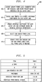
- the method is as follows described in the context of methodology 400 of FIG. 4 .
- step 402 we choose the largest power level consistent with not reducing the SINR below some predetermined threshold for all the active lines. Hence, we choose according to worst case crosstalk or bound on that over the active lines; alternatively, according to initial estimates if we have them.
- step 406 update the crosstalk coefficient for each line and determine bound on R k which is the residual crosstalk interference on line k after correction with the new crosstalk estimate.
- B k be a bounding random variable for R k with known parameters for B k . This could be R k itself if its probability distribution is known.
- step 408 select a new higher power level as large as possible consistent with the bounding random variables B k .
- the bounding random variables B k we permit acceptable levels of crosstalk interference, acceptable being defined stochastically.
- step 410 go to step 404, and repeat until full power level is reached on the joining line.
- This method can be optimized with the objective being to get to full power in the shortest number of steps. For example, optimization may be realized by more estimates at step 404 and larger power increases versus fewer estimates at step 404 and smaller power increases.
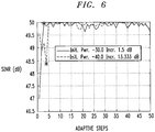
- FIG. 6 depicts two instances of this approach with results for the same active and new joining line.
- the solid curve is the first instance and shows that with the joining power level at -30 dB initially, the SINR drops by around 3 dB so that the crosstalking signal, at full power offset, is comparable to the noise.
- the last power increment took place prior to the SINR report at the star, which is therefore after two adaptive steps for a total of six SINR requests.
- the second dashed curve shows the second instance where the joining power level is smaller at -40 dB, the offset power is higher and the increment is smaller per adaptive steps.
- the initial SINR prior to acquisition is higher.
- a regression based hill climbing method may be employed. This method relies on representing the interference as a quadratic function of the error ⁇ in the crosstalk coefficients.
- the unknown coefficients of the quadratic can be estimated by using SINR estimates at various choices of operating point (settings of the precoder matrix). By using regression, theses estimates can be used to fix the quadratic.
- the fitted quadratic can then be used to determine the optimum operating point for the precoder.
- a direct adaptation of the precoder matrix may be performed. That is, the precoder can also be tuned by directly perturbing the precoder matrix itself as opposed to the estimates of the crosstalk coefficients ⁇ .
- C j denote column j of the precoder matrix.
- SINR i 1 ⁇ j f j C j + N ′
- f j is used to determine the interference as a function of the preorder matrix column C j .
- the SINR can be maximized by minimizing each f j in turn, with the effects of the column decoupled.
- a multi-variate optimization method such as Powell's line search technique as disclosed in W. Press et al., "Numerical Recipes in C: The Art of Scientific Computing," Cambridge University Press, 1992 .
- other appropriate techniques may be used.
- the self-tuning precoder techniques described herein may be employed with one or more of the channel estimate techniques disclosed in the concurrently filed U.S. patent applications respectively identified by attorney docket numbers Kramer 9-16-6 (entitled “Determining a Channel Matrix by Measuring Interference") and Guenach 1-12-1-1-1-1-1-20-1-9 (entitled “Determining Channel Matrices by Correlated Transmissions to Different Channels”), the disclosures of which are incorporated by reference herein.
Landscapes
- Engineering & Computer Science (AREA)
- Computer Networks & Wireless Communication (AREA)
- Signal Processing (AREA)
- Cable Transmission Systems, Equalization Of Radio And Reduction Of Echo (AREA)
Claims (9)
- Verfahren, umfassend:Erhalten einer ersten Reihe von geschätzten Nebensprechmessungen für mindestens einen ausgewählten Teil aus einer Vielzahl von Kommunikationskanälen (106), über die Datensignale von einem Sender an mindestens einen ausgewählten Teil aus einer Vielzahl von Empfängern (104) übertragen werden sollen;Anpassen einer ersten Reihe von Datensignalen basierend auf der ersten Reihe von geschätzten Nebensprechmessungen, um eine erste Reihe von angepassten Datensignalen zu erzeugen;Übertragen der ersten Reihe von angepassten Datensignalen an Entsprechende aus der Vielzahl von Empfängern (104);Erhalten einer zweiten Reihe von geschätzten Nebensprechmessungen für den ausgewählten Teil aus der Vielzahl von Kommunikationskanälen (106); undAnpassen einer zweiten Reihe von Datensignalen zur Übertragung, basierend auf der zweiten Reihe von geschätzten Nebensprechmessungen, um eine zweite Reihe von angepassten Datensignalen zu erzeugen;wobei die Wiederholung der Schritte des Erhaltens, Anpassens und Übertragens durchgeführt wird, um einen Fehler zwischen aufeinander folgenden geschätzten Nebensprechmessungen und tatsächlichen Nebensprechmessungen für die Vielzahl von Kommunikationskanälen (106) zu verringern;wobei die Schritte des Anpassens der ersten Reihe von Datensignalen und der zweiten Reihe von Datensignalen weiterhin jeweils das wiederholte Einstellen von Leistungspegeln von Entsprechenden der Datensignale umfassen; undwobei ein Leistungspegel gemäß einer Fehlerverteilung gewählt wird.
- Verfahren nach Anspruch 1, wobei die Schritte des Anpassens der ersten Reihe von Datensignalen und der zweiten Reihe von Datensignalen weiterhin jeweils das Adaptieren einer Vorcodierungsmatrix umfassen, die Elemente umfasst, die aus der erhaltenen Reihe von geschätzten Nebensprechmessungen erzeugt werden.
- Verfahren nach Anspruch 1, wobei die Schritte des Anpassens der ersten Reihe von Datensignalen und der zweiten Reihe von Datensignalen weiterhin jeweils das Hinzufügen von Anpassungssignalen zu Entsprechenden der Datensignale umfassen, wobei die Anpassungssignale basierend auf der erhaltenen Reihe von geschätzten Nebensprechmessungen erzeugt werden.
- Verfahren nach Anspruch 1, wobei die erste Reihe von geschätzten Nebensprechmessungen und die zweite Reihe von geschätzten Nebensprechmessungen aus Messungen des Signal/Störungs- und Signal/Rausch-Verhältnisses (SINR) erzeugt werden, die von der Vielzahl von Empfängern (104) empfangen werden.
- Verfahren nach Anspruch 1, wobei die erste Reihe von Datensignalen und die zweite Reihe von Datensignalen, die anzupassen sind, basierend auf einer Bestimmung ausgewählt werden, dass entsprechende Kanäle, über welche die Datensignale zu übertragen sind, mindestens einen anderen Kanal stören.
- Verfahren nach Anspruch 1, wobei die Reihe von geschätzten Nebensprechmessungen durch ein Differenzschätzungsverfahren erhalten wird.
- Vorrichtung, umfassend:einen Sender (102), der ausgelegt ist zum Erhalten einer ersten Reihe von geschätzten Nebensprechmessungen für mindestens einen ausgewählten Teil aus einer Vielzahl von Kommunikationskanälen (106), über die Datensignale von einem Sender an mindestens einen ausgewählten Teil aus einer Vielzahl von Empfängern (104) übertragen werden sollen, Anpassen einer ersten Reihe von Datensignalen basierend auf der ersten Reihe von geschätzten Nebensprechmessungen, um eine erste Reihe von angepassten Datensignalen zu erzeugen, Übertragen der ersten Reihe von angepassten Datensignalen an Entsprechende aus der Vielzahl von Empfängern (104), Erhalten einer zweiten Reihe von geschätzten Nebensprechmessungen für den ausgewählten Teil aus der Vielzahl von Kommunikationskanälen (106), und Anpassen einer zweiten Reihe von Datensignalen zur Übertragung, basierend auf der zweiten Reihe von geschätzten Nebensprechmessungen, um eine zweite Reihe von angepassten Datensignalen zu erzeugen, wobei die Wiederholung der Schritte des Erhaltens, Anpassens und Übertragens durchgeführt wird, um einen Fehler zwischen aufeinander folgenden geschätzten Nebensprechmessungen und tatsächlichen Nebensprechmessungen für die Vielzahl von Kommunikationskanälen (106) zu verringern, und wobei der Sender ausgelegt ist zum Anpassen der ersten Reihe von Datensignalen und der zweiten Reihe von Datensignalen durch wiederholtes Einstellen von Leistungspegeln von Entsprechenden der Datensignale, und wobei ein Leistungspegel gemäß einer Fehlerverteilung gewählt wird.
- Vorrichtung nach Anspruch 7, wobei die Vielzahl von Kommunikationsleitungen digitale Teilnehmeranschlüsse (DSL) eines DSL-Kommunikationssystems umfasst, und wobei sich der Sender an einem zentralen Büro des DSL-Kommunikationssystems befindet.
- Kommunikationssystem (100), umfassend:eine Vielzahl von Empfängern (104); undeinen Sender (102), der ausgelegt ist zum Erhalten einer ersten Reihe von geschätzten Nebensprechmessungen für mindestens einen ausgewählten Teil aus einer Vielzahl von Kommunikationskanälen (106), über die Datensignale von einem Sender an mindestens einen ausgewählten Teil aus einer Vielzahl von Empfängern (104) übertragen werden sollen, Anpassen einer ersten Reihe von Datensignalen basierend auf der ersten Reihe von geschätzten Nebensprechmessungen, um eine erste Reihe von angepassten Datensignalen zu erzeugen, Übertragen der ersten Reihe von angepassten Datensignalen an Entsprechende aus der Vielzahl von Empfängern (104), Erhalten einer zweiten Reihe von geschätzten Nebensprechmessungen für den ausgewählten Teil aus der Vielzahl von Kommunikationskanälen (106), und Anpassen einer zweiten Reihe von Datensignalen zur Übertragung, basierend auf der zweiten Reihe von geschätzten Nebensprechmessungen, um eine zweite Reihe von angepassten Datensignalen zu erzeugen, wobei die Wiederholung der Schritte des Erhaltens, Anpassens und Übertragens durchgeführt wird, um einen Fehler zwischen aufeinander folgenden geschätzten Nebensprechmessungen und tatsächlichen Nebensprechmessungen für die Vielzahl von Kommunikationskanälen (106) zu verringern, und wobei der Sender ausgelegt ist zum Anpassen der ersten Reihe von Datensignalen und der zweiten Reihe von Datensignalen durch wiederholtes Einstellen von Leistungspegeln von Entsprechenden der Datensignale, und wobei ein Leistungspegel gemäß einer Fehlerverteilung gewählt wird.
Applications Claiming Priority (2)
| Application Number | Priority Date | Filing Date | Title |
|---|---|---|---|
| US11/848,684 US8081560B2 (en) | 2007-08-31 | 2007-08-31 | Method and apparatus for self-tuning precoder |
| PCT/US2008/010057 WO2009032092A1 (en) | 2007-08-31 | 2008-08-25 | Method and apparatus for self-tuning precoder |
Publications (2)
| Publication Number | Publication Date |
|---|---|
| EP2198530A1 EP2198530A1 (de) | 2010-06-23 |
| EP2198530B1 true EP2198530B1 (de) | 2017-11-22 |
Family
ID=40085521
Family Applications (1)
| Application Number | Title | Priority Date | Filing Date |
|---|---|---|---|
| EP08795562.1A Not-in-force EP2198530B1 (de) | 2007-08-31 | 2008-08-25 | Verfahren und vorrichtung für einen selbstabstimmenden vorcodierer |
Country Status (5)
| Country | Link |
|---|---|
| US (1) | US8081560B2 (de) |
| EP (1) | EP2198530B1 (de) |
| KR (1) | KR101522237B1 (de) |
| CN (1) | CN101790851B (de) |
| WO (1) | WO2009032092A1 (de) |
Families Citing this family (24)
| Publication number | Priority date | Publication date | Assignee | Title |
|---|---|---|---|---|
| WO2008118048A1 (en) * | 2007-03-23 | 2008-10-02 | Telefonaktiebolaget L M Ericsson (Publ) | Methods and arrangements in a digital subscriber line network |
| US8717862B2 (en) * | 2008-01-07 | 2014-05-06 | Lantiq Deutschland Gmbh | Communication apparatus and method |
| US8306097B2 (en) * | 2008-06-04 | 2012-11-06 | Alcatel Lucent | Signal suspension and resumption in DSL systems |
| EP2282409A4 (de) * | 2008-06-20 | 2012-01-11 | Huawei Tech Co Ltd | Methode, vorrichtung und system zur kanalschätzung |
| US8275054B2 (en) * | 2008-08-21 | 2012-09-25 | Lantiq Deutschland Gmbh | Methods and apparatuses for data transmission |
| US7801017B2 (en) * | 2008-08-22 | 2010-09-21 | Alcatel-Lucent Usa Inc. | Communication system for improved cross talk estimation and method thereof |
| EP2319191A4 (de) * | 2008-08-23 | 2017-06-28 | Ikanos Communications, Inc. | Verfahren und vorrichtung zur dmt-nebensprechunterdrückung |
| US8179774B2 (en) * | 2009-01-30 | 2012-05-15 | Lantiq Deutschland Gmbh | Cross-talk coefficient updating in vector transmission |
| US8243578B2 (en) * | 2009-02-12 | 2012-08-14 | Alcatel Lucent | Simultaneous estimation of multiple channel coefficients using a common probing sequence |
| US8218419B2 (en) * | 2009-02-12 | 2012-07-10 | Alcatel Lucent | Simultaneous estimation of multiple channel coefficients using a common probing sequence |
| US8320432B1 (en) * | 2009-04-27 | 2012-11-27 | Indian Institute of Science at Bangalore | Device and method for precoding vectors in a communication system |
| US8433056B2 (en) * | 2009-05-02 | 2013-04-30 | Alcatel Lucent | Validated signal resumption in DSL systems |
| US9231656B2 (en) * | 2009-10-29 | 2016-01-05 | At&T Intellectual Property, I, L.P. | System and method to reduce crosstalk of digital subscriber lines |
| CN105471473A (zh) * | 2010-07-28 | 2016-04-06 | 伊卡诺斯通讯公司 | 改进矢量化数字用户线路的上行功率削减的系统和方法 |
| US8363789B2 (en) * | 2010-12-15 | 2013-01-29 | At&T Intellectual Property I, L.P. | Apparatus, methods, and articles of manufacture to predict vectored digital subscriber line (DSL) performance gains |
| CN103444156B (zh) * | 2011-02-23 | 2016-09-07 | 伊卡诺斯通讯公司 | 用于划分dsl矢量消除的系统和方法 |
| ES2798141T3 (es) * | 2011-08-29 | 2020-12-09 | Lantiq Beteiligungs Gmbh & Co Kg | Supervisión adaptativa de la intensidad del acoplamiento diafónico |
| EP2928167B1 (de) | 2012-12-26 | 2017-04-26 | Huawei Technologies Co., Ltd. | Verfahren und vorrichtung zur leitungsinitialisierung |
| CN106230480B (zh) * | 2013-03-15 | 2019-04-16 | 华为技术有限公司 | 一种dsl系统的参数调整方法和设备 |
| CN105591710B (zh) * | 2014-10-20 | 2018-07-13 | 中国电信股份有限公司 | 用于矢量化dsl快速初始化的方法、装置和系统 |
| EP3221972A1 (de) * | 2014-11-19 | 2017-09-27 | Lantiq Beteiligungs-GmbH & Co. KG | Erkennung von verbindungsverlust |
| US10038473B2 (en) * | 2015-01-30 | 2018-07-31 | Alcatel Lucent | Methods and systems for reducing crosstalk via stabilized vectoring control |
| US20160380673A1 (en) * | 2015-06-23 | 2016-12-29 | Ikanos Communications, Inc. | Vectoring across multiple co boxes/cards/dslams either owned by the same operator or by different operators |
| US11063629B1 (en) * | 2020-10-14 | 2021-07-13 | Nvidia Corporation | Techniques for detecting wireless communications interference from a wired communications channel |
Family Cites Families (13)
| Publication number | Priority date | Publication date | Assignee | Title |
|---|---|---|---|---|
| DE69915082D1 (de) | 1999-12-14 | 2004-04-01 | St Microelectronics Nv | DSL-Übertragungsystem mit Fernnebensprechkompensation |
| US6519705B1 (en) * | 1999-12-15 | 2003-02-11 | At&T Corp. | Method and system for power control in wireless networks using interference prediction with an error margin |
| US7433416B1 (en) * | 2000-08-02 | 2008-10-07 | Via Telecom Co., Ltd. | Method and apparatus for generating transmit adaptive antenna weights with nulling using binary gradient feedback |
| US6859622B1 (en) * | 2000-12-26 | 2005-02-22 | Nortel Networks Limited | Predictive optimization of wavelength division multiplexed systems |
| KR100442882B1 (ko) * | 2002-07-26 | 2004-08-02 | 삼성전자주식회사 | 홈 네트웍에서 스테이션 인식 및 링크 설정 방법 |
| US7164764B2 (en) * | 2002-11-07 | 2007-01-16 | Solarflare Communications, Inc. | Method and apparatus for precode crosstalk mitigation |
| CN1918870B (zh) * | 2004-02-05 | 2011-05-11 | 英特尔公司 | 减少mimo通信系统中的串扰的方法和装置 |
| US20060029148A1 (en) * | 2004-08-06 | 2006-02-09 | Tsatsanis Michail K | Method and apparatus for training using variable transmit signal power levels |
| KR20070108304A (ko) * | 2005-10-31 | 2007-11-09 | 삼성전자주식회사 | 다중 송수신 안테나 시스템에서의 채널 품질 정보 송수신방법 및 장치 |
| WO2008010057A2 (en) | 2006-07-14 | 2008-01-24 | Horn Andre J | Pre-adjusted self-aligner and method |
| US7852742B2 (en) * | 2006-12-01 | 2010-12-14 | Infineon Technologies Ag | Precompensation of crosstalk interference based on feedback error signal |
| US8290079B2 (en) * | 2007-04-19 | 2012-10-16 | Interdigital Technology Corporation | Method and apparatus for precoding validation in wireless communications |
| US8374275B2 (en) * | 2007-06-23 | 2013-02-12 | Panasonic Corporation | Method and system for communication channel optimization in a multiple-input multiple-output (MIMO) communication system |
-
2007
- 2007-08-31 US US11/848,684 patent/US8081560B2/en not_active Expired - Fee Related
-
2008
- 2008-08-25 WO PCT/US2008/010057 patent/WO2009032092A1/en not_active Ceased
- 2008-08-25 KR KR1020107004486A patent/KR101522237B1/ko not_active Expired - Fee Related
- 2008-08-25 CN CN2008801047563A patent/CN101790851B/zh not_active Expired - Fee Related
- 2008-08-25 EP EP08795562.1A patent/EP2198530B1/de not_active Not-in-force
Also Published As
| Publication number | Publication date |
|---|---|
| WO2009032092A1 (en) | 2009-03-12 |
| CN101790851B (zh) | 2013-07-03 |
| CN101790851A (zh) | 2010-07-28 |
| US8081560B2 (en) | 2011-12-20 |
| US20090059780A1 (en) | 2009-03-05 |
| KR20100049618A (ko) | 2010-05-12 |
| EP2198530A1 (de) | 2010-06-23 |
| KR101522237B1 (ko) | 2015-05-21 |
Similar Documents
| Publication | Publication Date | Title |
|---|---|---|
| EP2198530B1 (de) | Verfahren und vorrichtung für einen selbstabstimmenden vorcodierer | |
| EP2215739B1 (de) | Interpolationsverfahren und vorrichtung zur vergrösserung der effizienz der übersprechschätzung | |
| US8830812B2 (en) | Optimizing precoder settings using average SINR reports for groups of tones | |
| US9148803B2 (en) | MIMO channel state information estimation with coupled iterative two-stage ranking | |
| US8094745B2 (en) | Power control using denoised crosstalk estimates in a multi-channel communication system | |
| JP2014506754A (ja) | Dslmimoシステムにおけるクロストークの事前補償および事後補償のための方法およびデバイス | |
| KR101687929B1 (ko) | 다운스트림 벡터링 시스템들을 위한 이득 적응 | |
| EP3062471B1 (de) | Skalierte, orthogonale pilotsequenzen zur parallelen kanalschätzung | |
| CN114900216B (zh) | 大规模mimo鲁棒预编码器的迭代信干噪比设计方法 | |
| US7362828B2 (en) | Method of and system for optimizing the capacity of a digital communication system in presence of both internal and external noise | |
| Whiting et al. | DSL crosstalk coefficient acquisition using SNR feedback | |
| CN115459813A (zh) | Mimo系统的性能优化方法、装置、设备及存储介质 | |
| New Providence et al. | Van Wijngaarden et al. | |
| Peeters et al. | DSL Crosstalk Coefficient Acquisition Using SNR Feedback | |
| EP2503720A1 (de) | Spiralförmige Interpolation von Kopplungskoeffizienten |
Legal Events
| Date | Code | Title | Description |
|---|---|---|---|
| PUAI | Public reference made under article 153(3) epc to a published international application that has entered the european phase |
Free format text: ORIGINAL CODE: 0009012 |
|
| 17P | Request for examination filed |
Effective date: 20100331 |
|
| AK | Designated contracting states |
Kind code of ref document: A1 Designated state(s): AT BE BG CH CY CZ DE DK EE ES FI FR GB GR HR HU IE IS IT LI LT LU LV MC MT NL NO PL PT RO SE SI SK TR |
|
| AX | Request for extension of the european patent |
Extension state: AL BA MK RS |
|
| DAX | Request for extension of the european patent (deleted) | ||
| RAP1 | Party data changed (applicant data changed or rights of an application transferred) |
Owner name: ALCATEL-LUCENT USA INC. |
|
| 111Z | Information provided on other rights and legal means of execution |
Free format text: AT BE BG CH CY CZ DE DK EE ES FI FR GB GR HR HU IE IS IT LI LT LU LV MC MT NL NO PL PT RO SE SI SK TR Effective date: 20130410 |
|
| D11X | Information provided on other rights and legal means of execution (deleted) | ||
| STAA | Information on the status of an ep patent application or granted ep patent |
Free format text: STATUS: EXAMINATION IS IN PROGRESS |
|
| 17Q | First examination report despatched |
Effective date: 20170116 |
|
| GRAP | Despatch of communication of intention to grant a patent |
Free format text: ORIGINAL CODE: EPIDOSNIGR1 |
|
| STAA | Information on the status of an ep patent application or granted ep patent |
Free format text: STATUS: GRANT OF PATENT IS INTENDED |
|
| INTG | Intention to grant announced |
Effective date: 20170705 |
|
| GRAS | Grant fee paid |
Free format text: ORIGINAL CODE: EPIDOSNIGR3 |
|
| GRAA | (expected) grant |
Free format text: ORIGINAL CODE: 0009210 |
|
| STAA | Information on the status of an ep patent application or granted ep patent |
Free format text: STATUS: THE PATENT HAS BEEN GRANTED |
|
| AK | Designated contracting states |
Kind code of ref document: B1 Designated state(s): AT BE BG CH CY CZ DE DK EE ES FI FR GB GR HR HU IE IS IT LI LT LU LV MC MT NL NO PL PT RO SE SI SK TR |
|
| REG | Reference to a national code |
Ref country code: GB Ref legal event code: FG4D |
|
| REG | Reference to a national code |
Ref country code: CH Ref legal event code: EP |
|
| REG | Reference to a national code |
Ref country code: IE Ref legal event code: FG4D |
|
| REG | Reference to a national code |
Ref country code: AT Ref legal event code: REF Ref document number: 949287 Country of ref document: AT Kind code of ref document: T Effective date: 20171215 |
|
| REG | Reference to a national code |
Ref country code: DE Ref legal event code: R096 Ref document number: 602008053075 Country of ref document: DE |
|
| REG | Reference to a national code |
Ref country code: NL Ref legal event code: MP Effective date: 20171122 |
|
| REG | Reference to a national code |
Ref country code: LT Ref legal event code: MG4D |
|
| REG | Reference to a national code |
Ref country code: AT Ref legal event code: MK05 Ref document number: 949287 Country of ref document: AT Kind code of ref document: T Effective date: 20171122 |
|
| PG25 | Lapsed in a contracting state [announced via postgrant information from national office to epo] |
Ref country code: FI Free format text: LAPSE BECAUSE OF FAILURE TO SUBMIT A TRANSLATION OF THE DESCRIPTION OR TO PAY THE FEE WITHIN THE PRESCRIBED TIME-LIMIT Effective date: 20171122 Ref country code: NO Free format text: LAPSE BECAUSE OF FAILURE TO SUBMIT A TRANSLATION OF THE DESCRIPTION OR TO PAY THE FEE WITHIN THE PRESCRIBED TIME-LIMIT Effective date: 20180222 Ref country code: ES Free format text: LAPSE BECAUSE OF FAILURE TO SUBMIT A TRANSLATION OF THE DESCRIPTION OR TO PAY THE FEE WITHIN THE PRESCRIBED TIME-LIMIT Effective date: 20171122 Ref country code: SE Free format text: LAPSE BECAUSE OF FAILURE TO SUBMIT A TRANSLATION OF THE DESCRIPTION OR TO PAY THE FEE WITHIN THE PRESCRIBED TIME-LIMIT Effective date: 20171122 Ref country code: NL Free format text: LAPSE BECAUSE OF FAILURE TO SUBMIT A TRANSLATION OF THE DESCRIPTION OR TO PAY THE FEE WITHIN THE PRESCRIBED TIME-LIMIT Effective date: 20171122 Ref country code: LT Free format text: LAPSE BECAUSE OF FAILURE TO SUBMIT A TRANSLATION OF THE DESCRIPTION OR TO PAY THE FEE WITHIN THE PRESCRIBED TIME-LIMIT Effective date: 20171122 |
|
| PG25 | Lapsed in a contracting state [announced via postgrant information from national office to epo] |
Ref country code: BG Free format text: LAPSE BECAUSE OF FAILURE TO SUBMIT A TRANSLATION OF THE DESCRIPTION OR TO PAY THE FEE WITHIN THE PRESCRIBED TIME-LIMIT Effective date: 20180222 Ref country code: GR Free format text: LAPSE BECAUSE OF FAILURE TO SUBMIT A TRANSLATION OF THE DESCRIPTION OR TO PAY THE FEE WITHIN THE PRESCRIBED TIME-LIMIT Effective date: 20180223 Ref country code: AT Free format text: LAPSE BECAUSE OF FAILURE TO SUBMIT A TRANSLATION OF THE DESCRIPTION OR TO PAY THE FEE WITHIN THE PRESCRIBED TIME-LIMIT Effective date: 20171122 Ref country code: LV Free format text: LAPSE BECAUSE OF FAILURE TO SUBMIT A TRANSLATION OF THE DESCRIPTION OR TO PAY THE FEE WITHIN THE PRESCRIBED TIME-LIMIT Effective date: 20171122 Ref country code: HR Free format text: LAPSE BECAUSE OF FAILURE TO SUBMIT A TRANSLATION OF THE DESCRIPTION OR TO PAY THE FEE WITHIN THE PRESCRIBED TIME-LIMIT Effective date: 20171122 |
|
| PG25 | Lapsed in a contracting state [announced via postgrant information from national office to epo] |
Ref country code: CY Free format text: LAPSE BECAUSE OF FAILURE TO SUBMIT A TRANSLATION OF THE DESCRIPTION OR TO PAY THE FEE WITHIN THE PRESCRIBED TIME-LIMIT Effective date: 20171122 Ref country code: EE Free format text: LAPSE BECAUSE OF FAILURE TO SUBMIT A TRANSLATION OF THE DESCRIPTION OR TO PAY THE FEE WITHIN THE PRESCRIBED TIME-LIMIT Effective date: 20171122 Ref country code: SK Free format text: LAPSE BECAUSE OF FAILURE TO SUBMIT A TRANSLATION OF THE DESCRIPTION OR TO PAY THE FEE WITHIN THE PRESCRIBED TIME-LIMIT Effective date: 20171122 Ref country code: DK Free format text: LAPSE BECAUSE OF FAILURE TO SUBMIT A TRANSLATION OF THE DESCRIPTION OR TO PAY THE FEE WITHIN THE PRESCRIBED TIME-LIMIT Effective date: 20171122 Ref country code: CZ Free format text: LAPSE BECAUSE OF FAILURE TO SUBMIT A TRANSLATION OF THE DESCRIPTION OR TO PAY THE FEE WITHIN THE PRESCRIBED TIME-LIMIT Effective date: 20171122 |
|
| REG | Reference to a national code |
Ref country code: DE Ref legal event code: R097 Ref document number: 602008053075 Country of ref document: DE |
|
| PG25 | Lapsed in a contracting state [announced via postgrant information from national office to epo] |
Ref country code: IT Free format text: LAPSE BECAUSE OF FAILURE TO SUBMIT A TRANSLATION OF THE DESCRIPTION OR TO PAY THE FEE WITHIN THE PRESCRIBED TIME-LIMIT Effective date: 20171122 Ref country code: RO Free format text: LAPSE BECAUSE OF FAILURE TO SUBMIT A TRANSLATION OF THE DESCRIPTION OR TO PAY THE FEE WITHIN THE PRESCRIBED TIME-LIMIT Effective date: 20171122 Ref country code: PL Free format text: LAPSE BECAUSE OF FAILURE TO SUBMIT A TRANSLATION OF THE DESCRIPTION OR TO PAY THE FEE WITHIN THE PRESCRIBED TIME-LIMIT Effective date: 20171122 |
|
| PLBE | No opposition filed within time limit |
Free format text: ORIGINAL CODE: 0009261 |
|
| STAA | Information on the status of an ep patent application or granted ep patent |
Free format text: STATUS: NO OPPOSITION FILED WITHIN TIME LIMIT |
|
| 26N | No opposition filed |
Effective date: 20180823 |
|
| PG25 | Lapsed in a contracting state [announced via postgrant information from national office to epo] |
Ref country code: SI Free format text: LAPSE BECAUSE OF FAILURE TO SUBMIT A TRANSLATION OF THE DESCRIPTION OR TO PAY THE FEE WITHIN THE PRESCRIBED TIME-LIMIT Effective date: 20171122 |
|
| PG25 | Lapsed in a contracting state [announced via postgrant information from national office to epo] |
Ref country code: MC Free format text: LAPSE BECAUSE OF FAILURE TO SUBMIT A TRANSLATION OF THE DESCRIPTION OR TO PAY THE FEE WITHIN THE PRESCRIBED TIME-LIMIT Effective date: 20171122 |
|
| REG | Reference to a national code |
Ref country code: CH Ref legal event code: PL |
|
| PG25 | Lapsed in a contracting state [announced via postgrant information from national office to epo] |
Ref country code: LU Free format text: LAPSE BECAUSE OF NON-PAYMENT OF DUE FEES Effective date: 20180825 Ref country code: CH Free format text: LAPSE BECAUSE OF NON-PAYMENT OF DUE FEES Effective date: 20180831 Ref country code: LI Free format text: LAPSE BECAUSE OF NON-PAYMENT OF DUE FEES Effective date: 20180831 |
|
| REG | Reference to a national code |
Ref country code: DE Ref legal event code: R081 Ref document number: 602008053075 Country of ref document: DE Owner name: PROVENANCE ASSET GROUP LLC, ESSEX, US Free format text: FORMER OWNER: ALCATEL-LUCENT USA INC., MURRAY HILL, N.J., US |
|
| REG | Reference to a national code |
Ref country code: BE Ref legal event code: MM Effective date: 20180831 |
|
| REG | Reference to a national code |
Ref country code: GB Ref legal event code: 732E Free format text: REGISTERED BETWEEN 20190418 AND 20190426 |
|
| PG25 | Lapsed in a contracting state [announced via postgrant information from national office to epo] |
Ref country code: FR Free format text: LAPSE BECAUSE OF NON-PAYMENT OF DUE FEES Effective date: 20180831 Ref country code: BE Free format text: LAPSE BECAUSE OF NON-PAYMENT OF DUE FEES Effective date: 20180831 |
|
| PG25 | Lapsed in a contracting state [announced via postgrant information from national office to epo] |
Ref country code: MT Free format text: LAPSE BECAUSE OF NON-PAYMENT OF DUE FEES Effective date: 20180825 |
|
| PG25 | Lapsed in a contracting state [announced via postgrant information from national office to epo] |
Ref country code: TR Free format text: LAPSE BECAUSE OF FAILURE TO SUBMIT A TRANSLATION OF THE DESCRIPTION OR TO PAY THE FEE WITHIN THE PRESCRIBED TIME-LIMIT Effective date: 20171122 |
|
| PG25 | Lapsed in a contracting state [announced via postgrant information from national office to epo] |
Ref country code: HU Free format text: LAPSE BECAUSE OF FAILURE TO SUBMIT A TRANSLATION OF THE DESCRIPTION OR TO PAY THE FEE WITHIN THE PRESCRIBED TIME-LIMIT; INVALID AB INITIO Effective date: 20080825 Ref country code: PT Free format text: LAPSE BECAUSE OF FAILURE TO SUBMIT A TRANSLATION OF THE DESCRIPTION OR TO PAY THE FEE WITHIN THE PRESCRIBED TIME-LIMIT Effective date: 20171122 |
|
| PG25 | Lapsed in a contracting state [announced via postgrant information from national office to epo] |
Ref country code: IE Free format text: LAPSE BECAUSE OF NON-PAYMENT OF DUE FEES Effective date: 20180825 |
|
| PG25 | Lapsed in a contracting state [announced via postgrant information from national office to epo] |
Ref country code: IS Free format text: LAPSE BECAUSE OF FAILURE TO SUBMIT A TRANSLATION OF THE DESCRIPTION OR TO PAY THE FEE WITHIN THE PRESCRIBED TIME-LIMIT Effective date: 20180322 |
|
| PGFP | Annual fee paid to national office [announced via postgrant information from national office to epo] |
Ref country code: GB Payment date: 20200909 Year of fee payment: 13 Ref country code: DE Payment date: 20200901 Year of fee payment: 13 |
|
| REG | Reference to a national code |
Ref country code: DE Ref legal event code: R119 Ref document number: 602008053075 Country of ref document: DE |
|
| GBPC | Gb: european patent ceased through non-payment of renewal fee |
Effective date: 20210825 |
|
| PG25 | Lapsed in a contracting state [announced via postgrant information from national office to epo] |
Ref country code: GB Free format text: LAPSE BECAUSE OF NON-PAYMENT OF DUE FEES Effective date: 20210825 Ref country code: DE Free format text: LAPSE BECAUSE OF NON-PAYMENT OF DUE FEES Effective date: 20220301 |