EP2198193B1 - Greifersegment für einen greifring und entsprechender klemmring - Google Patents
Greifersegment für einen greifring und entsprechender klemmring Download PDFInfo
- Publication number
- EP2198193B1 EP2198193B1 EP08840976.8A EP08840976A EP2198193B1 EP 2198193 B1 EP2198193 B1 EP 2198193B1 EP 08840976 A EP08840976 A EP 08840976A EP 2198193 B1 EP2198193 B1 EP 2198193B1
- Authority
- EP
- European Patent Office
- Prior art keywords
- profile
- segment
- apex
- claw
- clamping collar
- Prior art date
- Legal status (The legal status is an assumption and is not a legal conclusion. Google has not performed a legal analysis and makes no representation as to the accuracy of the status listed.)
- Active
Links
Images
Classifications
-
- F—MECHANICAL ENGINEERING; LIGHTING; HEATING; WEAPONS; BLASTING
- F16—ENGINEERING ELEMENTS AND UNITS; GENERAL MEASURES FOR PRODUCING AND MAINTAINING EFFECTIVE FUNCTIONING OF MACHINES OR INSTALLATIONS; THERMAL INSULATION IN GENERAL
- F16L—PIPES; JOINTS OR FITTINGS FOR PIPES; SUPPORTS FOR PIPES, CABLES OR PROTECTIVE TUBING; MEANS FOR THERMAL INSULATION IN GENERAL
- F16L21/00—Joints with sleeve or socket
- F16L21/06—Joints with sleeve or socket with a divided sleeve or ring clamping around the pipe ends
- F16L21/065—Joints with sleeve or socket with a divided sleeve or ring clamping around the pipe ends tightened by tangentially-arranged threaded pins
-
- F—MECHANICAL ENGINEERING; LIGHTING; HEATING; WEAPONS; BLASTING
- F16—ENGINEERING ELEMENTS AND UNITS; GENERAL MEASURES FOR PRODUCING AND MAINTAINING EFFECTIVE FUNCTIONING OF MACHINES OR INSTALLATIONS; THERMAL INSULATION IN GENERAL
- F16L—PIPES; JOINTS OR FITTINGS FOR PIPES; SUPPORTS FOR PIPES, CABLES OR PROTECTIVE TUBING; MEANS FOR THERMAL INSULATION IN GENERAL
- F16L21/00—Joints with sleeve or socket
- F16L21/08—Joints with sleeve or socket with additional locking means
Definitions
- the present invention relates to a clamp, of the type indicated in the preamble of claim 1.
- Such a hose clamp is known to DE19802676 .
- the invention applies to claw collars for locking tubular links.
- Knuckle collars are known in the state of the art used to lock tight connections between two pipes with plain ends.
- claw collars comprise claw segments adapted to bite into the outer surface of the plain ends.
- the segments are provided with a plurality of claws, claws whose ends in contact with the end are sometimes sometimes pointed, such as a V-shaped, sometimes rectangular.
- these segments have a pressure resistance which can be limited because of the compromise to be found between the size of the contact surface of the tooth on the spigot and thus the effectiveness of the penetration of the tooth into the tooth. spigot, and the intrinsic resistance of the tooth.
- claw segments are difficult to manufacture since the tip of each claw often requires cutting or complex machining of tools themselves fragile because of the desired angles in the final parts.
- the object of the invention is to propose a non-dangerous claw segment to be handled which can be manufactured in an economical manner and which makes it possible to obtain good performance in terms of holding the claw collar.
- the subject of the invention is a clamping collar of the aforementioned type, characterized by the features of claim 1.
- the clamping collar comprises one or more of the features indicated in claims 2 to 9.
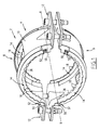
- This claw collar 2 is adapted to lock with respect to one another two unrepresented plain ends, and to prevent axial separation of the two ends united when a fluid under pressure is located therein.
- the claw collar 2 extends around a central axis XX.
- the expressions “axially”, “radially” and “circumferentially” will be used with respect to this central axis XX.
- the claw collar 2 has a first set 4 for a claw collar and a second assembly 6 for a claw collar.
- the first set 4 and the second set 6 are, except the clamping means, identical. Accordingly, in what follows only the first set 4 will be described.
- the assembly 4 for a claw collar comprises a base body 8 or a half-cage which comprises a central portion 10 and two attachment flanges 12.
- the base body 8 extends around the central axis XX on a beach angle less than 180 ° to ensure the tightness of the two plain ends.
- the assembly 4 is further provided with two claw segments 14, one of which is disposed on each axial side of the base body 8.
- Each clawed segment 14 extends around the central axis X-X about an angular range smaller than the angular range of the base body 8.
- the claw segment 14 is shown in more detail on the Figure 2 .
- the clawed segment 14 has a segment body 16 and a plurality of claws 18 disposed on a radially inner portion of the segment body 16.
- the claws 18 are adapted to catch on the outer surface of a spigot.
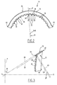
- the segment body 16 has a generally frustoconical shape and delimits a frustoconical outer surface 20 and a frustoconical inner surface 22 (see FIG. Figure 3 ).
- the two outer and inner surfaces 22 are parallel to each other.
- the outer surface 20 is delimited by an outer generator GE and the inner surface 22 is delimited by an inner generator GI.
- Each of the generators GE and GI is oblique with respect to the axis X-X and is inclined at a first angle ⁇ relative to a plane P perpendicular to this axis. In the free state of the clamp and therefore the segment, the angle ⁇ is for example and preferably between 30 ° and 50 °.
- the generators GE and GI are generatrices of enveloping surfaces of the segment with claws 14.
- the segment body 16 delimits a smooth radially outer edge 24 and a radially inner edge 26 on which the claws 18 are present.
- the outer edge 24 is delimited by a surface which is inclined at 90 ° with respect to the outer and inner surfaces 22 and 22.
- the inner edge 26 is indicated in dashed lines in the figures, since the segment body 16 and the claws 18 are made in one piece. As this is visible on the Figure 1 , the inner edges 26 of the two claw segments 14 are directed axially towards each other.
- each claw 18 has an apex 28, which is the radially inner end of the claw 18. This apex 28 first comes into contact with the surface of the spigot when clamping.
- Each claw 18 defines a crown domain 30 extending circumferentially on either side of the vertex 28.
- the crown domain 30 has a convex profile which is curved continuously over its entire circumferential extent. The profile is viewed in a direction perpendicular to the outer surface 20 (or the course of the segment 14 on a flat surface).
- the profile of the vertex domain 30 has a shape of a circular arc or a sinusoidal shape.
- valley domain 32 Two adjacent vertex domains are separated by a valley domain 32 having a concave profile.
- the profile of each valley domain 32 is also continuously curved over the entire circumferential extent of the valley domain 32.
- the valley domain profile 32 has a circular arc shape or a sinusoidal shape.
- the profile of the valley domain 32 is also seen in a direction perpendicular to the outer surface 20 or the course of the segment 14 on a flat surface.
- valley domain profiles 32 and adjacent vertex domains 30 are connected to each other in a continuous manner.
- the claw segment 14 defines claws 18 having a wavy shape.
- This form favors the fact of attacking the plain ends on a very small surface, theoretically punctual for each tooth at the beginning of the tightening, while offering the possibility, as the accentuation of the tightening, and thus the depth of attack, the tooth in the spigot, to regulate the internal stresses to the tooth by an increase in the attack surface
- the vertex domains 30 and the valley domains 32 form a front surface 34.
- the profile of each vertex domain 30 is delimited by a GS vertex generator.
- the profile of each valley area 32 is delimited by a GV valley generator.
- GS and GV valley generators are inclined at a second angle ⁇ with respect to the central axis X-X.
- the GS and GV valley generators, and thus the front surface 34, are inclined 90 ° to the outer and inner surfaces 22.
- the claw segment 14 may comprise two attachment lugs 50 adapted to cooperate with fixing recesses 52 formed in the base body 8.
- the claw segment is manufactured in the following manner.
- a claw segment blank is cut by stamping a sheet blank.
- the segment blank has substantially a flat shape corresponding to the unwinding of the claw segment 14 in a plane.
- the segment may be subjected to a heat treatment to obtain the necessary properties such as, for example, the surface hardness at the teeth or the resistance to corrosion.
- the shape of the claw segment 14, and in particular of the front surface 34 can be obtained exclusively by these two processes stamping and bending without any additional operation such as punching or sharpening.
- the claw segment 14 according to the invention is particularly easy to manufacture, with tools of fragility and low maintenance, and the corrugated shape of the claws allows a good holding of the clamp while reducing the risk of injury to people brought to assemble or use them.
Landscapes
- Engineering & Computer Science (AREA)
- General Engineering & Computer Science (AREA)
- Mechanical Engineering (AREA)
- Clamps And Clips (AREA)
- Gears, Cams (AREA)
- Mutual Connection Of Rods And Tubes (AREA)
- Prostheses (AREA)
Claims (9)
- Rohrschelle, umfassend- einen Grundkörper (8), und- ein Zahnsegment (14) für eine Zahnrohrschelle,wobei das Zahnsegment (14) umfasst:- einen Segmentkörper (16), und- eine Vielzahl von Zähnen (18), die einen Scheitelbereich (30) mit einem konvexen Profil begrenzen,
wobei das Profil des oder jedes Scheitelbereichs (30) kontinuierlich gekrümmt ist und der Segmentkörper (16) kegelstumpfförmige Außenflächen (20) und kegelstumpfförmige Innenflächen (22) aufweist, dadurch gekennzeichnet, dass- der Grundkörper sich um eine Mittelachse (X-X) über einen Winkelbereich kleiner als 180° erstreckt, dass- das Profil des oder jedes Scheitelbereichs (30) durch eine Scheitelerzeugende (GS) begrenzt ist, die um 90° in Bezug auf die Außenfläche (20) und die Innenfläche (22) geneigt ist, dass- der Segmentkörper (16) einen radial außenliegenden Rand (24) begrenzt, der durch eine Fläche, die um 90° in Bezug auf die Außenfläche (20) und die Innenfläche (21) geneigt ist, begrenzt ist, und dass
jedes Zahnsegment (14) sich um die Mittelachse (X-X) über einen Winkelbereich erstreckt, der kleiner als der Winkelbereich des Grundkörpers (8) ist. - Rohrschelle nach Anspruch 1, dadurch gekennzeichnet, dass das Profil des oder jedes Scheitelbereichs (30) eine Kreisbogenform aufweist.
- Rohrschelle nach Anspruch 1, dadurch gekennzeichnet, dass das Profil des oder jedes Scheitelbereichs (30) eine Sinusform aufweist.
- Rohrschelle nach einem beliebigen der Ansprüche 1 bis 3, dadurch gekennzeichnet, dass zwei benachbarte Scheitelbereiche (30) durch einen Talbereich (32) getrennt sind, der ein konkaves Profil aufweist, und dass das Profil des oder jedes Talbereichs (30) kontinuierlich gekrümmt ist.
- Rohrschelle nach Anspruch 4, dadurch gekennzeichnet, dass das Profil des oder jedes Talbereichs (32) eine Kreisbogenform aufweist.
- Rohrschelle nach Anspruch 4, dadurch gekennzeichnet, dass das Profil des oder jedes Talbereichs (32) eine Sinusform aufweist.
- Rohrschelle nach einem beliebigen der Ansprüche 4 bis 6, dadurch gekennzeichnet, dass sich die Profile des Talbereichs (32) und der benachbarten Scheitelbereiche (30) in kontinuierlicher Weise verbinden.
- Rohrschelle nach einem beliebigen der vorhergehenden Ansprüche, dadurch gekennzeichnet, dass mindestens eine der Innenfläche und Außenfläche (20, 22) durch eine schräge Erzeugende (GE, GI) begrenzt ist, die um einen ersten Winkel (α) in Bezug auf eine senkrechte Ebene (P) zur Mittelachse geneigt ist, und dass die oder jede Scheitelerzeugende (GS) um einen zweiten Winkel (β) in Bezug auf diese Mittelachse geneigt ist.
- Rohrschelle nach einem beliebigen der Ansprüche 4 bis 7 und dem Anspruch 8 zusammengenommen, dadurch gekennzeichnet, dass das Profil des oder jedes Talbereichs (32) durch eine Erzeugende (GV) definiert ist, die in Bezug auf die Mittelachse um einen Winkel geneigt ist, der identisch zu dem zweiten Winkel (β) der Scheitelbereiche ist.
Applications Claiming Priority (2)
| Application Number | Priority Date | Filing Date | Title |
|---|---|---|---|
| FR0758139A FR2921985B1 (fr) | 2007-10-08 | 2007-10-08 | Segment a griffes pour collier a griffes et collier de serrage correspondant |
| PCT/FR2008/051809 WO2009053603A2 (fr) | 2007-10-08 | 2008-10-07 | Segment a griffes pour collier a griffes et collier de serrage correspondant |
Publications (2)
| Publication Number | Publication Date |
|---|---|
| EP2198193A2 EP2198193A2 (de) | 2010-06-23 |
| EP2198193B1 true EP2198193B1 (de) | 2015-08-26 |
Family
ID=39367522
Family Applications (1)
| Application Number | Title | Priority Date | Filing Date |
|---|---|---|---|
| EP08840976.8A Active EP2198193B1 (de) | 2007-10-08 | 2008-10-07 | Greifersegment für einen greifring und entsprechender klemmring |
Country Status (5)
| Country | Link |
|---|---|
| EP (1) | EP2198193B1 (de) |
| FR (1) | FR2921985B1 (de) |
| RU (1) | RU2449200C2 (de) |
| TW (1) | TWI421429B (de) |
| WO (1) | WO2009053603A2 (de) |
Families Citing this family (8)
| Publication number | Priority date | Publication date | Assignee | Title |
|---|---|---|---|---|
| DK177164B1 (da) | 2010-02-26 | 2012-04-02 | Bluecher Metal As | Låsebøjle samt fremgangsmåde til fastholdelse af en muffesamling samt anvendelse af sådan låsebøjle |
| RU2516330C2 (ru) * | 2012-09-12 | 2014-05-20 | Открытое акционерное общество "Приволжские магистральные нефтепроводы" (ОАО Приволжскнефтепровод") | Способ получения заготовки замка трубопровода |
| US10578234B2 (en) | 2013-05-02 | 2020-03-03 | Victaulic Company | Coupling having arcuate stiffness ribs |
| CA3009356C (en) | 2015-12-28 | 2020-07-21 | Victaulic Company | Adapter coupling |
| US10605394B2 (en) | 2016-05-16 | 2020-03-31 | Victaulic Company | Fitting having tabbed retainer and observation apertures |
| US10533688B2 (en) | 2016-05-16 | 2020-01-14 | Victaulic Company | Coupling having tabbed retainer |
| US10859190B2 (en) | 2016-05-16 | 2020-12-08 | Victaulic Company | Sprung coupling |
| DE102019104026A1 (de) * | 2019-02-18 | 2020-08-20 | E.K. SML Verbindungstechnik GmbH | Verbindungsvorrichtung für Rohre |
Family Cites Families (6)
| Publication number | Priority date | Publication date | Assignee | Title |
|---|---|---|---|---|
| DE3710852C1 (de) * | 1987-04-01 | 1988-03-10 | Rasmussen Gmbh | Rohrkupplung |
| DE19802676C1 (de) * | 1998-01-24 | 1999-05-06 | Rasmussen Gmbh | Spannbare Rohrkupplung |
| DE10123925A1 (de) * | 2001-03-17 | 2002-10-02 | Rasmussen Gmbh | Rohrschelle |
| SE524585C2 (sv) * | 2002-03-04 | 2004-08-31 | Aba Sweden Ab | Kopplingsanordning för rör innefattande två ledbara halvor |
| DE102005055382A1 (de) * | 2005-11-17 | 2007-05-24 | Peter Ilesic | Spannring einer spannbaren Rohrkupplung |
| DE102005057670B4 (de) * | 2005-12-01 | 2009-12-10 | J. Eberspächer GmbH & Co. KG | Rohrverbindung |
-
2007
- 2007-10-08 FR FR0758139A patent/FR2921985B1/fr active Active
-
2008
- 2008-10-07 TW TW97138547A patent/TWI421429B/zh not_active IP Right Cessation
- 2008-10-07 RU RU2010117214/06A patent/RU2449200C2/ru not_active IP Right Cessation
- 2008-10-07 EP EP08840976.8A patent/EP2198193B1/de active Active
- 2008-10-07 WO PCT/FR2008/051809 patent/WO2009053603A2/fr not_active Ceased
Also Published As
| Publication number | Publication date |
|---|---|
| EP2198193A2 (de) | 2010-06-23 |
| TWI421429B (zh) | 2014-01-01 |
| FR2921985B1 (fr) | 2013-03-15 |
| FR2921985A1 (fr) | 2009-04-10 |
| RU2010117214A (ru) | 2011-11-20 |
| WO2009053603A2 (fr) | 2009-04-30 |
| TW200928162A (en) | 2009-07-01 |
| WO2009053603A3 (fr) | 2009-06-25 |
| RU2449200C2 (ru) | 2012-04-27 |
Similar Documents
| Publication | Publication Date | Title |
|---|---|---|
| EP2198193B1 (de) | Greifersegment für einen greifring und entsprechender klemmring | |
| EP0870967B1 (de) | Verriegelte Verbindung für Rohrleitungen und geschlitzter Metallring zur Verwendung in einer solchen Verbindung | |
| EP1064489B1 (de) | Steck-kupplung für rohre | |
| EP2029931B1 (de) | Klemmring | |
| WO1997016670A1 (fr) | Joint d'etancheite composite, et ensemble comportant un tel joint | |
| EP2789888B1 (de) | Spannvorrichtung zum dichten Verbinden von Glattrohren | |
| FR2652874A1 (fr) | Accouplement pour flexibles, a dissociation aisee. | |
| WO2003048624A1 (fr) | Systeme de serrage pour le raccordement etanche de deux tubes ayant des surfaces d'appui. | |
| EP2207988B1 (de) | Vorrichtung für eine griffrosette, griffrosette und entsprechender röhrenkonnektor | |
| EP2185852A2 (de) | Griffrosettenanordnung, entsprechende griffrosette und röhrenverbindung | |
| FR2880670A1 (fr) | Embout de raccordement pour tube annele et tube equipe d'un tel embout | |
| EP0559542B1 (de) | Kupplung aus einem Stück | |
| FR2810378A1 (fr) | Systeme de liaison mecanique entre deux pieces | |
| EP1231422B1 (de) | Verfahren zur Herstellung einer unverlierbaren Schraube, Fixierungstellringe für Rohrleitungen und Gebrauch von dem Prozess, die Stellringe herzustellen | |
| EP1303724B1 (de) | Schnellverbindungsstück | |
| EP2923132B1 (de) | Dichtungsanordnung für eine rohrverbindung und zugehörige rohrförmige verbindung | |
| EP1186821A1 (de) | Rohrkupplung | |
| FR2727043A1 (fr) | Element de centrage pour un trepan, notamment une cloche de percage comportant un foret de centrage a plusieurs bras de fixation radialement en saillie | |
| FR2588357A1 (fr) | Conduit de fumee metallique a simple paroi | |
| CH628128A5 (fr) | Raccord de tuyau. | |
| FR2894011A1 (fr) | Systeme de raccordement etanche entre une extremite d'un tube rigide et une extremite d'un tuyau souple d'une canalisation de transfert de fluide. | |
| EP1987311A1 (de) | Metallischer verteiler, wärmetauscher mit derartigem verteiler und herstellungsverfahren dafür | |
| WO2012004475A2 (fr) | Collier de dérivation pour une canalisation de fluide, eau ou gaz par exemple | |
| FR2884577A1 (fr) | Joint annulaire pour raccord de transfert de fluide et raccord equipe d'un tel joint | |
| FR2683291A1 (fr) | Anneau d'etancheite symetrique. |
Legal Events
| Date | Code | Title | Description |
|---|---|---|---|
| PUAI | Public reference made under article 153(3) epc to a published international application that has entered the european phase |
Free format text: ORIGINAL CODE: 0009012 |
|
| 17P | Request for examination filed |
Effective date: 20100304 |
|
| AK | Designated contracting states |
Kind code of ref document: A2 Designated state(s): AT BE BG CH CY CZ DE DK EE ES FI FR GB GR HR HU IE IS IT LI LT LU LV MC MT NL NO PL PT RO SE SI SK TR |
|
| AX | Request for extension of the european patent |
Extension state: AL BA MK RS |
|
| 17Q | First examination report despatched |
Effective date: 20120330 |
|
| RAP1 | Party data changed (applicant data changed or rights of an application transferred) |
Owner name: SAINT-GOBAIN PAM |
|
| REG | Reference to a national code |
Ref country code: DE Ref legal event code: R079 Ref document number: 602008039843 Country of ref document: DE Free format text: PREVIOUS MAIN CLASS: F16L0021060000 Ipc: F16L0021080000 |
|
| GRAP | Despatch of communication of intention to grant a patent |
Free format text: ORIGINAL CODE: EPIDOSNIGR1 |
|
| RIC1 | Information provided on ipc code assigned before grant |
Ipc: F16L 21/06 20060101ALI20150311BHEP Ipc: F16L 21/08 20060101AFI20150311BHEP |
|
| INTG | Intention to grant announced |
Effective date: 20150327 |
|
| GRAS | Grant fee paid |
Free format text: ORIGINAL CODE: EPIDOSNIGR3 |
|
| GRAA | (expected) grant |
Free format text: ORIGINAL CODE: 0009210 |
|
| AK | Designated contracting states |
Kind code of ref document: B1 Designated state(s): AT BE BG CH CY CZ DE DK EE ES FI FR GB GR HR HU IE IS IT LI LT LU LV MC MT NL NO PL PT RO SE SI SK TR |
|
| AX | Request for extension of the european patent |
Extension state: AL BA MK RS |
|
| REG | Reference to a national code |
Ref country code: GB Ref legal event code: FG4D Free format text: NOT ENGLISH |
|
| REG | Reference to a national code |
Ref country code: CH Ref legal event code: EP |
|
| REG | Reference to a national code |
Ref country code: AT Ref legal event code: REF Ref document number: 745389 Country of ref document: AT Kind code of ref document: T Effective date: 20150915 |
|
| REG | Reference to a national code |
Ref country code: IE Ref legal event code: FG4D Free format text: LANGUAGE OF EP DOCUMENT: FRENCH |
|
| REG | Reference to a national code |
Ref country code: DE Ref legal event code: R096 Ref document number: 602008039843 Country of ref document: DE Ref country code: FR Ref legal event code: PLFP Year of fee payment: 8 |
|
| REG | Reference to a national code |
Ref country code: AT Ref legal event code: MK05 Ref document number: 745389 Country of ref document: AT Kind code of ref document: T Effective date: 20150826 |
|
| REG | Reference to a national code |
Ref country code: LT Ref legal event code: MG4D |
|
| PG25 | Lapsed in a contracting state [announced via postgrant information from national office to epo] |
Ref country code: FI Free format text: LAPSE BECAUSE OF FAILURE TO SUBMIT A TRANSLATION OF THE DESCRIPTION OR TO PAY THE FEE WITHIN THE PRESCRIBED TIME-LIMIT Effective date: 20150826 Ref country code: GR Free format text: LAPSE BECAUSE OF FAILURE TO SUBMIT A TRANSLATION OF THE DESCRIPTION OR TO PAY THE FEE WITHIN THE PRESCRIBED TIME-LIMIT Effective date: 20151127 Ref country code: LV Free format text: LAPSE BECAUSE OF FAILURE TO SUBMIT A TRANSLATION OF THE DESCRIPTION OR TO PAY THE FEE WITHIN THE PRESCRIBED TIME-LIMIT Effective date: 20150826 Ref country code: NO Free format text: LAPSE BECAUSE OF FAILURE TO SUBMIT A TRANSLATION OF THE DESCRIPTION OR TO PAY THE FEE WITHIN THE PRESCRIBED TIME-LIMIT Effective date: 20151126 Ref country code: LT Free format text: LAPSE BECAUSE OF FAILURE TO SUBMIT A TRANSLATION OF THE DESCRIPTION OR TO PAY THE FEE WITHIN THE PRESCRIBED TIME-LIMIT Effective date: 20150826 |
|
| REG | Reference to a national code |
Ref country code: NL Ref legal event code: MP Effective date: 20150826 |
|
| PG25 | Lapsed in a contracting state [announced via postgrant information from national office to epo] |
Ref country code: PL Free format text: LAPSE BECAUSE OF FAILURE TO SUBMIT A TRANSLATION OF THE DESCRIPTION OR TO PAY THE FEE WITHIN THE PRESCRIBED TIME-LIMIT Effective date: 20150826 Ref country code: SE Free format text: LAPSE BECAUSE OF FAILURE TO SUBMIT A TRANSLATION OF THE DESCRIPTION OR TO PAY THE FEE WITHIN THE PRESCRIBED TIME-LIMIT Effective date: 20150826 Ref country code: PT Free format text: LAPSE BECAUSE OF FAILURE TO SUBMIT A TRANSLATION OF THE DESCRIPTION OR TO PAY THE FEE WITHIN THE PRESCRIBED TIME-LIMIT Effective date: 20151228 Ref country code: IS Free format text: LAPSE BECAUSE OF FAILURE TO SUBMIT A TRANSLATION OF THE DESCRIPTION OR TO PAY THE FEE WITHIN THE PRESCRIBED TIME-LIMIT Effective date: 20151226 Ref country code: AT Free format text: LAPSE BECAUSE OF FAILURE TO SUBMIT A TRANSLATION OF THE DESCRIPTION OR TO PAY THE FEE WITHIN THE PRESCRIBED TIME-LIMIT Effective date: 20150826 Ref country code: HR Free format text: LAPSE BECAUSE OF FAILURE TO SUBMIT A TRANSLATION OF THE DESCRIPTION OR TO PAY THE FEE WITHIN THE PRESCRIBED TIME-LIMIT Effective date: 20150826 Ref country code: ES Free format text: LAPSE BECAUSE OF FAILURE TO SUBMIT A TRANSLATION OF THE DESCRIPTION OR TO PAY THE FEE WITHIN THE PRESCRIBED TIME-LIMIT Effective date: 20150826 |
|
| PG25 | Lapsed in a contracting state [announced via postgrant information from national office to epo] |
Ref country code: NL Free format text: LAPSE BECAUSE OF FAILURE TO SUBMIT A TRANSLATION OF THE DESCRIPTION OR TO PAY THE FEE WITHIN THE PRESCRIBED TIME-LIMIT Effective date: 20150826 |
|
| PG25 | Lapsed in a contracting state [announced via postgrant information from national office to epo] |
Ref country code: SK Free format text: LAPSE BECAUSE OF FAILURE TO SUBMIT A TRANSLATION OF THE DESCRIPTION OR TO PAY THE FEE WITHIN THE PRESCRIBED TIME-LIMIT Effective date: 20150826 Ref country code: EE Free format text: LAPSE BECAUSE OF FAILURE TO SUBMIT A TRANSLATION OF THE DESCRIPTION OR TO PAY THE FEE WITHIN THE PRESCRIBED TIME-LIMIT Effective date: 20150826 Ref country code: IT Free format text: LAPSE BECAUSE OF FAILURE TO SUBMIT A TRANSLATION OF THE DESCRIPTION OR TO PAY THE FEE WITHIN THE PRESCRIBED TIME-LIMIT Effective date: 20150826 Ref country code: CZ Free format text: LAPSE BECAUSE OF FAILURE TO SUBMIT A TRANSLATION OF THE DESCRIPTION OR TO PAY THE FEE WITHIN THE PRESCRIBED TIME-LIMIT Effective date: 20150826 Ref country code: DK Free format text: LAPSE BECAUSE OF FAILURE TO SUBMIT A TRANSLATION OF THE DESCRIPTION OR TO PAY THE FEE WITHIN THE PRESCRIBED TIME-LIMIT Effective date: 20150826 |
|
| REG | Reference to a national code |
Ref country code: DE Ref legal event code: R097 Ref document number: 602008039843 Country of ref document: DE |
|
| PG25 | Lapsed in a contracting state [announced via postgrant information from national office to epo] |
Ref country code: RO Free format text: LAPSE BECAUSE OF FAILURE TO SUBMIT A TRANSLATION OF THE DESCRIPTION OR TO PAY THE FEE WITHIN THE PRESCRIBED TIME-LIMIT Effective date: 20150826 Ref country code: LU Free format text: LAPSE BECAUSE OF FAILURE TO SUBMIT A TRANSLATION OF THE DESCRIPTION OR TO PAY THE FEE WITHIN THE PRESCRIBED TIME-LIMIT Effective date: 20151007 |
|
| REG | Reference to a national code |
Ref country code: CH Ref legal event code: PL |
|
| PG25 | Lapsed in a contracting state [announced via postgrant information from national office to epo] |
Ref country code: MC Free format text: LAPSE BECAUSE OF FAILURE TO SUBMIT A TRANSLATION OF THE DESCRIPTION OR TO PAY THE FEE WITHIN THE PRESCRIBED TIME-LIMIT Effective date: 20150826 |
|
| PLBE | No opposition filed within time limit |
Free format text: ORIGINAL CODE: 0009261 |
|
| STAA | Information on the status of an ep patent application or granted ep patent |
Free format text: STATUS: NO OPPOSITION FILED WITHIN TIME LIMIT |
|
| REG | Reference to a national code |
Ref country code: IE Ref legal event code: MM4A |
|
| PG25 | Lapsed in a contracting state [announced via postgrant information from national office to epo] |
Ref country code: LI Free format text: LAPSE BECAUSE OF NON-PAYMENT OF DUE FEES Effective date: 20151031 Ref country code: CH Free format text: LAPSE BECAUSE OF NON-PAYMENT OF DUE FEES Effective date: 20151031 |
|
| 26N | No opposition filed |
Effective date: 20160530 |
|
| PG25 | Lapsed in a contracting state [announced via postgrant information from national office to epo] |
Ref country code: SI Free format text: LAPSE BECAUSE OF FAILURE TO SUBMIT A TRANSLATION OF THE DESCRIPTION OR TO PAY THE FEE WITHIN THE PRESCRIBED TIME-LIMIT Effective date: 20150826 |
|
| REG | Reference to a national code |
Ref country code: FR Ref legal event code: PLFP Year of fee payment: 9 |
|
| PG25 | Lapsed in a contracting state [announced via postgrant information from national office to epo] |
Ref country code: IE Free format text: LAPSE BECAUSE OF NON-PAYMENT OF DUE FEES Effective date: 20151007 |
|
| PG25 | Lapsed in a contracting state [announced via postgrant information from national office to epo] |
Ref country code: BG Free format text: LAPSE BECAUSE OF FAILURE TO SUBMIT A TRANSLATION OF THE DESCRIPTION OR TO PAY THE FEE WITHIN THE PRESCRIBED TIME-LIMIT Effective date: 20150826 Ref country code: HU Free format text: LAPSE BECAUSE OF FAILURE TO SUBMIT A TRANSLATION OF THE DESCRIPTION OR TO PAY THE FEE WITHIN THE PRESCRIBED TIME-LIMIT; INVALID AB INITIO Effective date: 20081007 |
|
| PG25 | Lapsed in a contracting state [announced via postgrant information from national office to epo] |
Ref country code: CY Free format text: LAPSE BECAUSE OF FAILURE TO SUBMIT A TRANSLATION OF THE DESCRIPTION OR TO PAY THE FEE WITHIN THE PRESCRIBED TIME-LIMIT Effective date: 20150826 |
|
| PG25 | Lapsed in a contracting state [announced via postgrant information from national office to epo] |
Ref country code: BE Free format text: LAPSE BECAUSE OF NON-PAYMENT OF DUE FEES Effective date: 20151031 |
|
| PG25 | Lapsed in a contracting state [announced via postgrant information from national office to epo] |
Ref country code: MT Free format text: LAPSE BECAUSE OF FAILURE TO SUBMIT A TRANSLATION OF THE DESCRIPTION OR TO PAY THE FEE WITHIN THE PRESCRIBED TIME-LIMIT Effective date: 20150826 |
|
| REG | Reference to a national code |
Ref country code: FR Ref legal event code: PLFP Year of fee payment: 10 |
|
| PGFP | Annual fee paid to national office [announced via postgrant information from national office to epo] |
Ref country code: FR Payment date: 20170918 Year of fee payment: 10 |
|
| PGFP | Annual fee paid to national office [announced via postgrant information from national office to epo] |
Ref country code: TR Payment date: 20171005 Year of fee payment: 10 Ref country code: DE Payment date: 20171004 Year of fee payment: 10 |
|
| PGFP | Annual fee paid to national office [announced via postgrant information from national office to epo] |
Ref country code: GB Payment date: 20171004 Year of fee payment: 10 |
|
| REG | Reference to a national code |
Ref country code: DE Ref legal event code: R119 Ref document number: 602008039843 Country of ref document: DE |
|
| GBPC | Gb: european patent ceased through non-payment of renewal fee |
Effective date: 20181007 |
|
| PG25 | Lapsed in a contracting state [announced via postgrant information from national office to epo] |
Ref country code: DE Free format text: LAPSE BECAUSE OF NON-PAYMENT OF DUE FEES Effective date: 20190501 |
|
| PG25 | Lapsed in a contracting state [announced via postgrant information from national office to epo] |
Ref country code: FR Free format text: LAPSE BECAUSE OF NON-PAYMENT OF DUE FEES Effective date: 20181031 |
|
| PG25 | Lapsed in a contracting state [announced via postgrant information from national office to epo] |
Ref country code: GB Free format text: LAPSE BECAUSE OF NON-PAYMENT OF DUE FEES Effective date: 20181007 |
|
| PG25 | Lapsed in a contracting state [announced via postgrant information from national office to epo] |
Ref country code: TR Free format text: LAPSE BECAUSE OF NON-PAYMENT OF DUE FEES Effective date: 20181007 |