EP2197356B1 - Apparatus for a suprapubic transurethral cystostomy - Google Patents
Apparatus for a suprapubic transurethral cystostomy Download PDFInfo
- Publication number
- EP2197356B1 EP2197356B1 EP08834232.4A EP08834232A EP2197356B1 EP 2197356 B1 EP2197356 B1 EP 2197356B1 EP 08834232 A EP08834232 A EP 08834232A EP 2197356 B1 EP2197356 B1 EP 2197356B1
- Authority
- EP
- European Patent Office
- Prior art keywords
- cutting tip
- distal portion
- tubular body
- catheter
- advancement member
- Prior art date
- Legal status (The legal status is an assumption and is not a legal conclusion. Google has not performed a legal analysis and makes no representation as to the accuracy of the status listed.)
- Active
Links
- 210000003708 urethra Anatomy 0.000 claims description 29
- 210000003815 abdominal wall Anatomy 0.000 claims description 27
- 239000000463 material Substances 0.000 claims description 12
- 230000007246 mechanism Effects 0.000 claims description 9
- 238000003780 insertion Methods 0.000 claims description 7
- 230000037431 insertion Effects 0.000 claims description 7
- 230000000295 complement effect Effects 0.000 claims 2
- 238000000034 method Methods 0.000 description 49
- 210000001015 abdomen Anatomy 0.000 description 19
- 210000003811 finger Anatomy 0.000 description 9
- 239000003550 marker Substances 0.000 description 5
- 230000006378 damage Effects 0.000 description 4
- 239000012530 fluid Substances 0.000 description 4
- 230000035515 penetration Effects 0.000 description 4
- 230000008569 process Effects 0.000 description 4
- 238000001356 surgical procedure Methods 0.000 description 4
- 210000001519 tissue Anatomy 0.000 description 4
- 206010046555 Urinary retention Diseases 0.000 description 3
- 239000007769 metal material Substances 0.000 description 3
- 239000004033 plastic Substances 0.000 description 3
- 229920003023 plastic Polymers 0.000 description 3
- 208000019206 urinary tract infection Diseases 0.000 description 3
- 239000000853 adhesive Substances 0.000 description 2
- 230000001070 adhesive effect Effects 0.000 description 2
- 238000010276 construction Methods 0.000 description 2
- 230000000994 depressogenic effect Effects 0.000 description 2
- 238000001990 intravenous administration Methods 0.000 description 2
- 230000007774 longterm Effects 0.000 description 2
- 230000000149 penetrating effect Effects 0.000 description 2
- 229920001296 polysiloxane Polymers 0.000 description 2
- 239000000243 solution Substances 0.000 description 2
- 229910001220 stainless steel Inorganic materials 0.000 description 2
- 239000010935 stainless steel Substances 0.000 description 2
- 238000003466 welding Methods 0.000 description 2
- 208000031729 Bacteremia Diseases 0.000 description 1
- 206010071445 Bladder outlet obstruction Diseases 0.000 description 1
- 206010063575 Bladder perforation Diseases 0.000 description 1
- 208000031481 Pathologic Constriction Diseases 0.000 description 1
- 206010039897 Sedation Diseases 0.000 description 1
- 229910000639 Spring steel Inorganic materials 0.000 description 1
- 206010065810 Urethral perforation Diseases 0.000 description 1
- 208000003800 Urinary Bladder Neck Obstruction Diseases 0.000 description 1
- 206010046543 Urinary incontinence Diseases 0.000 description 1
- 230000009471 action Effects 0.000 description 1
- 230000032683 aging Effects 0.000 description 1
- 230000001580 bacterial effect Effects 0.000 description 1
- 230000015572 biosynthetic process Effects 0.000 description 1
- 239000008280 blood Substances 0.000 description 1
- 210000004369 blood Anatomy 0.000 description 1
- 230000001419 dependent effect Effects 0.000 description 1
- 201000010099 disease Diseases 0.000 description 1
- 208000037265 diseases, disorders, signs and symptoms Diseases 0.000 description 1
- 238000001125 extrusion Methods 0.000 description 1
- 210000004247 hand Anatomy 0.000 description 1
- 208000015181 infectious disease Diseases 0.000 description 1
- 238000001746 injection moulding Methods 0.000 description 1
- 238000002690 local anesthesia Methods 0.000 description 1
- 238000005259 measurement Methods 0.000 description 1
- 239000002184 metal Substances 0.000 description 1
- 238000012986 modification Methods 0.000 description 1
- 230000004048 modification Effects 0.000 description 1
- 210000000056 organ Anatomy 0.000 description 1
- 230000037361 pathway Effects 0.000 description 1
- 230000001681 protective effect Effects 0.000 description 1
- 210000003689 pubic bone Anatomy 0.000 description 1
- 230000002787 reinforcement Effects 0.000 description 1
- 230000036280 sedation Effects 0.000 description 1
- 239000007787 solid Substances 0.000 description 1
- 230000001954 sterilising effect Effects 0.000 description 1
- 238000004659 sterilization and disinfection Methods 0.000 description 1
- 239000003356 suture material Substances 0.000 description 1
- 210000003813 thumb Anatomy 0.000 description 1
- 210000002700 urine Anatomy 0.000 description 1
- 210000001835 viscera Anatomy 0.000 description 1
- 230000000007 visual effect Effects 0.000 description 1
- XLYOFNOQVPJJNP-UHFFFAOYSA-N water Substances O XLYOFNOQVPJJNP-UHFFFAOYSA-N 0.000 description 1
Images


Classifications
-
- A—HUMAN NECESSITIES
- A61—MEDICAL OR VETERINARY SCIENCE; HYGIENE
- A61B—DIAGNOSIS; SURGERY; IDENTIFICATION
- A61B17/00—Surgical instruments, devices or methods, e.g. tourniquets
- A61B17/34—Trocars; Puncturing needles
- A61B17/3415—Trocars; Puncturing needles for introducing tubes or catheters, e.g. gastrostomy tubes, drain catheters
-
- A—HUMAN NECESSITIES
- A61—MEDICAL OR VETERINARY SCIENCE; HYGIENE
- A61B—DIAGNOSIS; SURGERY; IDENTIFICATION
- A61B17/00—Surgical instruments, devices or methods, e.g. tourniquets
- A61B17/34—Trocars; Puncturing needles
- A61B17/3403—Needle locating or guiding means
-
- A—HUMAN NECESSITIES
- A61—MEDICAL OR VETERINARY SCIENCE; HYGIENE
- A61B—DIAGNOSIS; SURGERY; IDENTIFICATION
- A61B17/00—Surgical instruments, devices or methods, e.g. tourniquets
- A61B17/34—Trocars; Puncturing needles
- A61B17/3462—Trocars; Puncturing needles with means for changing the diameter or the orientation of the entrance port of the cannula, e.g. for use with different-sized instruments, reduction ports, adapter seals
-
- A—HUMAN NECESSITIES
- A61—MEDICAL OR VETERINARY SCIENCE; HYGIENE
- A61B—DIAGNOSIS; SURGERY; IDENTIFICATION
- A61B17/00—Surgical instruments, devices or methods, e.g. tourniquets
- A61B17/00234—Surgical instruments, devices or methods, e.g. tourniquets for minimally invasive surgery
- A61B2017/00238—Type of minimally invasive operation
- A61B2017/00278—Transorgan operations, e.g. transgastric
-
- A—HUMAN NECESSITIES
- A61—MEDICAL OR VETERINARY SCIENCE; HYGIENE
- A61B—DIAGNOSIS; SURGERY; IDENTIFICATION
- A61B17/00—Surgical instruments, devices or methods, e.g. tourniquets
- A61B17/34—Trocars; Puncturing needles
- A61B2017/348—Means for supporting the trocar against the body or retaining the trocar inside the body
- A61B2017/3482—Means for supporting the trocar against the body or retaining the trocar inside the body inside
- A61B2017/3484—Anchoring means, e.g. spreading-out umbrella-like structure
-
- A—HUMAN NECESSITIES
- A61—MEDICAL OR VETERINARY SCIENCE; HYGIENE
- A61B—DIAGNOSIS; SURGERY; IDENTIFICATION
- A61B90/00—Instruments, implements or accessories specially adapted for surgery or diagnosis and not covered by any of the groups A61B1/00 - A61B50/00, e.g. for luxation treatment or for protecting wound edges
- A61B90/06—Measuring instruments not otherwise provided for
- A61B2090/062—Measuring instruments not otherwise provided for penetration depth
Definitions
- This invention relates generally to an apparatus for forming a surgical opening and providing guidance for an instrument while inside a body cavity with an external guidance apparatus, and more particularly to an apparatus for performing a transurethral (inside-out) suprapubic cystostomy, associated urological procedures and other surgical procedures.
- bladder emptying problems either urinary retention, or urinary incontinence.
- BOO bladder outlet obstruction/urinary retention
- Some conditions require only a temporary solution, while others may require a more permanent solution.
- the first method is known as clean intermittent self-catheterization (CISC). As the name suggests, this method is performed by the patient, using a clean but typically non-sterile technique 3 to 4 times daily.
- the patient inserts a catheter into their bladder through the urethra at regular intervals over the course of the day.
- a catheter into their bladder through the urethra at regular intervals over the course of the day.
- this is presently believed to be the preferred method, it can be painful, awkward, depending on available privacy, and otherwise difficult, particularly for modest, elderly and/or incapacitated persons.
- complications such as urethral perforation, bladder perforation or stricture formation can occur, particularly in men, and urinary tract infections (UTI) often result from performing the procedure as the procedure is generally "clean" but not sterile.
- the second method is known as a urethral Foley catheterization (UFC).
- UFC urethral Foley catheterization
- a physician or nurse inserts a Foley catheter into the bladder through the urethra.
- the Foley catheter has an internal balloon near its tip that is inflated to maintain the catheter within the bladder.
- urinary tract infections occur generally at a rate of 3-10 percent per day with an indwelling catheter maintained within the bladder, with about 5 percent of the patients developing bacterial blood infections (bacteremia).
- the third method is known as a suprapubic cystostomy (SPC), and it includes two different types of procedures that are performed by a urologist usually employing intravenous (IV) sedation or local anesthesia while usually under hospital care. These procedures can be performed as a standalone procedure or in conjunction with another in unrelated surgical procedures.
- the first procedure is commonly referred to as a percutaneous or "outside-in” trocar punch procedure, and the second procedure is conversely referred to as a transurethral ("inside-out") or endocystostomy procedure.
- the SPC methods are predominantly used in the U.S. when long-term drainage is desired, and it is used internationally for both short and long-term drainage.
- the percutaneous punch "outside-in" procedure is by far the more commonly used method of the two, and it entails inserting a large bore hollow needle through the abdomen and then into the bladder. This procedure requires the bladder to be inflated or distended with water to create a firm abdomen to push against while inserting the hollow bore needle due to tissue resistance.
- the percutaneous punch method whereby a hollow needle is pushed through the abdomen into the bladder is a blind procedure and relies on physical feel and skill and experience of the physician to safely puncture the bladder. Thereafter, a smaller catheter is inserted through the hollow needle into the bladder.
- Drawbacks to this method include unreliable drainage due to a high rate of clogging and kinking of the catheter drainage tube.
- the percutaneous punch method has increased safety issues with high morbidity and mortality rate near 2%, usually from unrecognized puncturing of bowel. These two procedures cannot be safely performed on the morbidly obese patient, a patient population that is increasing, currently estimated to be more than 12 percent of this targeted patient population.
- the current transurethral ("inside-out") procedure is performed by inserting a hollow instrument with a blunt tip, commonly referred to as a sound, through the urethra into the bladder.
- the Sound has a tip that is typically advanced to penetrate through the bladder and abdominal wall and extend outside the abdomen.
- the surgeon is usually required to make an incision in the abdomen and facia, down to the tip of the sound to allow the blunt tip of the sound to advance through the abdomen exiting the skin.
- the surgeon must make a larger incision in the abdomen with a scalpel to allow for attachment of the catheter while the sound tip resides inside the abdomen.
- a catheter is attached to the end of the sound and drawn back into the bladder and out of the patient through the urethra along with the withdrawn sound.
- the catheter is then detached from the sound and pulled back into the bladder, whereupon a balloon on the catheter is inflated in an effort to maintain the catheter in a desired position within the bladder.
- Some of the drawbacks to this method include, a relatively high cost of the reusable surgical instruments, requiring sterilization between procedures, the catheter can be difficult to attach to the sound and once attached can disconnect during the procedure requiring the procedure to be repeated, the location of the deflated catheter balloon within the bladder can be difficult to ascertain prior to inflating the catheter balloon, and additionally, it can often not be effectively used to safely perform the procedure on obese and morbidly obese patients.
- the invention provides a suprapubic transurethral cystostomy apparatus according to claim 1, with further optional features as set out in the dependent claims.
- the method includes providing an elongate tubular body having a proximal end and a distal portion and inserting the distal portion through the urethra and into the bladder. Further, providing an elongate arm having a first end and a second end having an indicator establishing an axis and operably attaching the first end of the ann with the proximal portion of the tubular body and positioning the indicator externally over the abdominal wall with the axis arranged in coaxial alignment with the distal portion of the tubular body. Then, puncturing an opening with a cutting member extending along the axis through the bladder and through the abdominal wall.
- Figures 1 and 2 illustrate a suprapubic transurethral cystostomy apparatus 10 constructed in accordance with one aspect of the invention.
- the apparatus 10 and its associated individual components can be modified, while having a generally similar construction, and can be further modified to accommodate any size male or female, adult or pediatric patient, including obese and morbidly obese patients.
- female and male organs, particularly the urethra are shaped differently and have differing lengths and diameters, and so, the construction of the apparatus 10 can be varied to accommodate those differences.
- the apparatus 10 includes an elongate hollow tubular body, generally referred to as a sound 12, and an elongate positioning, referred to hereafter as alignment guide arm 14, adapted for operable attachment to the sound 12 in a predetermined position relative to the sound 12.
- the sound 12 is configured for insertion through a urethra 16 into a bladder 18, while the alignment guide arm 14 remains outside the patient to indicate the precise exit location of a trocar, referred to hereafter as cutting tip 20, extending from a the sound 12 through an abdominal wall 22 of the patient.
- the alignment guide ann 14 can be positioned to abut the abdominal wall 22 to provide a clamping action against the abdominal wall 22, thereby holding the instrument in place and providing tensile reinforcement of the patient's surface skin to allow the cutting tip 20 to cleanly pierce the skin as it extends outwardly through abdomen without stretching or tearing of the skin.
- the alignment guide arm 14 allows the surgeon to readily identify the precise location of the cutting tip 20 while in its blind location within the bladder 18, thereby enabling the surgeon to puncture a surgical pathway, referred to hereafter as an opening 24, through the bladder 18 and the abdomen wall 22 at a precise and intended location.
- the surgeon is provided with an increased level of confidence that the opening 24 formed by the cutting tip 20 is at the desired location, will be clean without tearing, and is further assured that inadvertent damage to internal organs, such as the bowel, is avoided.
- a catheter 26 Figure 14
- the alignment guide ann 14 not only provides a precise exit location for the cutting tip 20, but it can also be used to establish a precise linear path along which to form the opening 24 using an outside-in cut, such as by using an external trocar punch, for example, and extending the external trocar along a line established by the alignment guide arm 14, discussed further below.
- the sound 12 has a proximal portion 28 and a distal portion 30, with the distal portion 30 being configured for insertion into the bladder 18 through the urethra 16 (e.g., Figure 8 ).
- the proximal portion 28 and the distal portion 30 have respective linear sections that are inclined relative to one another at a predetermined and generally fixed obtuse angle of inclusion 32, such that the angle between the respective linear sections remains generally fixed in use.
- the proximal portion 28 can have measured indicator markings 33 to indicate to the surgeon the depth of insertion of the sound 12 into the urethra 16.
- a penetration depth marker also referred to as an indicator slide 35 can be disposed on the proximal portion 28 to assist in identifying the depth and location of the sound 12 within the bladder 18 during the procedure.
- the sound 12 is constructed from a material that can be readily sterilized, such as stainless steel, by way of example and without limitation. It should be recognized that other materials which can be readily sterilized are contemplated and incorporated herein within the scope of the invention, including plastics materials, for example.
- the sound 12, although constructed from a material capable of being sterilized, is preferably constructed as a disposable, single use instrument.
- the proximal portion 28 is fixedly connected to a front handle 34 which has a straight, tubular body 36 extending rearwardly away from the sound 12 to an end 38.
- the front handle 34 provides a reliable and comfortable location for grasping and manipulating the sound 12.
- the front handle 34 can be provided having any suitable shape and configuration, depending on the requirements of the surgeon.
- the front handle 34 can be ergonomically designed for left and right handed physicians and designed for optimal manipulation, control and orientation of the sound 12 while preventing hand slippage when wet and in contact with surgical gloves. Accordingly, it is contemplated that the front handle 34 can be provided having different shapes and contours, as desired.
- the front handle 34 and tubular body 36 can be molded as single piece halves and then subsequently joined, such as via fasteners, an adhesive or via welding, for example.
- the front handle 34 and tubular body 36 can be formed using any suitable plastic or metal materials and processes.
- the front handle 34 has an upstanding housing, referred to hereafter as mount sleeve 40, configured for releasable attachment of a straight slide arm, referred to hereafter as mast 42, thereto.
- mount sleeve 40 has a pocket 44 sized for close receipt of one end 46 of the mast 42 therein.
- the mount sleeve 40 has a releasable mast locking mechanism 48, represented here, by way of example and without limitation, as an over-center cam latch lever 50.
- the cam latch lever 50 has a cam surface 52 that frictionally engages the mast 42 when the lever 50 is in a depressed, locked position, thereby maintaining the mast 42 in a fixed position within the pocket 44. Otherwise, when the lever 50 is pivoted to a raised, unlocked position, the cam surface 52 is moved out of engagement with the mast 42, thereby allowing the mast 42 to be removed from the pocket 44.
- the pocket 44 is configured to extend along a straight, linear axis 54, whereby the mast 42, upon being locked within the pocket 44 also extends along the axis 54.
- the axis 54 is oriented to extend substantially parallel to the distal portion 30 of the sound 12.
- the mast 42 and the distal portion 30 of the sound 12 extend parallel or substantially parallel to one another.
- the angle of the mast 42 extending from the front handle 34 is configured to properly align the alignment guide arm 14 and a capture cup assembly 96 in the proper position to accept the cutting tip 20. This is of great assistance to the surgeon, as the surgeon otherwise would not have a visual location of the cutting tip 20 when inside the bladder 18.
- the front handle 34 further includes a cutting tip locking mechanism 56, represented here, by way of example and without limitation, as having a rotatable brake knob or wheel 58, a cam member 60 fixed to the wheel 58 for conjoint rotation therewith, such as by being formed as a single piece of material therewith, and a spring member, referred to hereafter as a brake spring 62.
- a cutting tip locking mechanism 56 represented here, by way of example and without limitation, as having a rotatable brake knob or wheel 58, a cam member 60 fixed to the wheel 58 for conjoint rotation therewith, such as by being formed as a single piece of material therewith, and a spring member, referred to hereafter as a brake spring 62.
- the tubular body 36 extends rear-ward from the rear of the front handle 34 a predetermined distance sufficient to provide the range of movement of the cutting tip 20 desired. It should be recognized that the range of movement of the cutting tip 20 will generally be less for a normal sized patient than for an obese or morbidly obese patient, and that the range of movement of the cutting tip 20 can be provided to accommodate any size patient.
- the tubular body 36 has tubular wall with an elongate slot 64 extending along its length, wherein the length of the slot 64 corresponds at least to the desired distance of travel of the cutting tip 20.
- the slot 64 is represented here as extending of the full length of the tubular body 36 along a bottom side thereof.
- the wall of the tubular body 36 is also represented, by way of example and without limitation, as having an upstanding rib 66 extending along an upper side of the wall diametrically opposite the slot 64.
- the upper side of the tubular wall preferably has measured scale markings 67 to indicate to the surgeon the distance the cutting tip 20 is extended, discussed further below.
- the apparatus 10 further includes an advancement member 68, represented here as a flexible coil rod or flat spring member, with a distal end 70 being operably attached to the cutting tip 20 and a proximal end 72 being attached to a rear handle 74 of the apparatus 10.
- the distal end 70 is represented here as having a connector 71 for selective, releasable attachment of the cutting tip 20 thereto.
- the connector 71 is a modified bayonet-type connector, for example, having at least one ramped, spiral shaped entry slot 73 terminating at a recessed lock detent.
- the proximal end 72 is fixed to the rear handle 74, such as by generally narrow connector plate 78 sized to slide through the slot 64.
- the connector plate 78 can be fixed to the advancement member 68, such as by a weld joint, for example, and to the rear handle 74 via a fastener 80, for example. Accordingly, movement of the rear handle 74 causes conjoint movement of the connector plate 78 and the advancement member 68.
- the advancement member 68 can be provided of any suitable material flexible enough to traverse the bend in the sound 12 between the proximal portion 28 and the distal portion 30, while being rigid enough to maintain a straight cutting path through the bladder 18 and abdominal wall 22, such as stainless steel or spring steel, for example.
- the advancement member 68 can further be provided as a single piece of material or multiple pieces of material joined to one another.
- the advancement member 68 has a plurality of circumferential notches 76 spaced in axially uniform relation from one another along a proximal or rear portion thereof for operable locking engagement with the brake spring 62.
- the notches 76 extend over the full portion that traverses beneath the cutting tip lock mechanism 56, thereby allowing the cutting tip 20 to be locked in a fully retracted position and in a fully extended position, as well as over a plurality of locations between the fully retracted and extended positions.
- the rear handle 74 can be provided having any suitable shape and configuration.
- the rear handle 74 can be ergonomically designed for left and right handed physicians and designed for optimal manipulation, control and orientation of the advancement member 68 and cutting tip 20 while preventing hand slippage when wet and in contact with surgical gloves.
- the rear handle 74 can be molded as single piece halves, with the halves being subsequently joined, such as via fasteners, an adhesive or via welding, for example, and can be formed using any suitable plastic or metal materials and processes.
- the rear handle 74 is formed having a through passage 82 sized for close sliding receipt over the tubular body 36.
- the passage 82 can be provided with a recessed notch 84 sized to slidingly receive the upstanding rib 66 therein, thereby preventing rotation of the rear handle 74 about the tubular body 36. This prevents unwanted rotation of the cutting tip 20 while forming the opening through the tissue.
- the mast 42 has a straight, elongate body 86 extending between the end 46 received in the pocket 44 of the front handle 34 and an opposite end 87.
- the body 86 preferably has measured scale markings 88 to facilitate indicating to the surgeon the distance over which the cutting tip 20 generally needs to extend through the abdomen of the patient.
- the body 86 can be formed as a solid body or a hollowed body using any desired process, such as extrusion, for example, and can be formed of any suitable polymeric or metal material, as desired.
- the body 86 is represented here as being generally rectangular in lateral cross-section, which assists in maintaining the alignment guide arm 14 in its proper orientation by preventing unwanted relative pivoting between the arm 14 and the positioning mast 42, although any cross-sectional geometry could be used.
- the body 86 can be provided of any suitable length, and preferably has a length between about 38-50 cm (15-20 inches), thereby allowing suitable adjustment of the alignment guide arm 14 on morbidly obese patients.
- the alignment guide arm 14 has body 90 that extends between a first end 92 and a second end 94.
- the first end 92 is configured for operable attachment to the proximal portion 28 of the sound 12 and for sliding receipt along the mast 42.
- the second end 94 is configured for attachment to the capture cup 96.
- the first end 92 has a through opening 98 configured for close sliding receipt of the mast body 86. Accordingly, the through opening 98 is shaped having a similar cross-sectional geometry as the mast body 86, though being slightly larger to facilitate sliding movement along the mast body 86.
- the first end 92 has a releasable arm locking mechanism 100, represented here, by way of example and without limitation, as an over-center cam latch lever 102.
- the cam latch lever 102 has a cam surface 104 that frictionally engages the mast 42 when the lever 102 is in a depressed, locked position, thereby maintaining the alignment guide arm 14 in a fixed position along the mast body 86 at the desired position. Otherwise, when the lever 102 is pivoted to a raised, unlocked position, the cam surface 104 is moved out of engagement with the mast body 86, thereby allowing the alignment guide arm 14 to be slid freely along the length of the mast body 86.
- the second end 94 of the alignment guide arm 14 has a semi-annular or annular housing 106 providing a through passage 108 of a predetermined diameter that extends along an axis 110 that is coaxial with the distal portion 30 of the sound 12 when then alignment guide arm 14 is attached to the mast 42, and the mast 42 is received in the mount sleeve 40.
- the housing 106 is further represented here, by way of example and without limitation, as having an upper surface with one or more lateral slots 112 configured to releasably receive the capture cup 96.
- the through passage 108 of the housing 106 can be provided having a funnel shape with an enlarged diameter 114 located adjacent a bottom surface of the housing 106 and a reduced diameter 116 located adjacent the upper surface of the housing 106.
- the capture cup 96 has a closed upper portion 118 configured to be easily grasped and rotated, and is represented here, by way of example and without limitation, as having a generally rectangular wall with opposite sides easily graspable between a thumb and index finger. As best shown in Figures 13A and 13B , a generally cylindrical, annular wall 120 depends from the upper portion 118, wherein the annular wall 120 is sized for close sliding receipt in the housing 106 of the alignment guide arm 14. Further, as shown in Figures 1 and 9-13 , the capture cup 96 has one or more fingers 122 extending laterally outwardly for sliding receipt in the slots 112 of the housing 106.
- the fingers 122 extend outwardly to engage the upper surface of the housing 106, and are received in the slots 112 by rotating the capture cup 96 relative to the housing 106. Accordingly, upon rotating the capture cup 96 in one direction, the fingers 122 slide in the slots 112 and engage a bottom surface of the slots 112, wherein the capture cup 96 is releasably locked to the housing 1065 and upon rotating the capture cup 96 in the opposite direction, the fingers 122 exit the slots 112, wherein the capture cup 96 can be removed from the housing.
- a bore or cavity of the capture cup 96 can be provided with an annular elastomeric wall or sleeve 124, such as an silicone tubing, for example, wherein the sleeve 124 has a slightly reduced diameter from the outer periphery of the cutting tip 20 to cause the cutting tip 20 to cut into the sleeve 124 upon being inserted therein, thereby being captured within the capture cup 96 for hands free disposal.
- a stop surface 125 can be provided to abut the cutting tip 20, thereby acting as a positive stop to limit the distance the cutting tip 20 can be inserted into the capture cup 96.
- the capture cup 96 is shown having the fingers 122 for releasable receipt in the slots 112, other attachment mechanisms are contemplated herein, such as a threaded attachment or the capture cup could be formed as a single piece of material with the alignment guide arm 14.
- a plurality of ribs can extend radially inwardly from the inner surface of the sleeve 124 to provide a bearing surface against the flat cutting blade as a 'stop' when rotating the capture cup 96. This further assures the cutting tip 20 will be rotated conjointly with the capture cup 96 while rotating the capture cup 96.
- the cutting tip 20 is constructed having a metal cutting member 126 and a connector 128 depending therefrom.
- the cutting member 126 is illustrated as having one or more openings 130 to facilitate attachment of the cutting member 126 to the connector 128.
- the connector 128 can be formed of an polymeric material, and further, can be molded, such as in an injection molding process, for example, to the cutting member 126.
- the connector 128 has a corresponding number of bayonets or fingers 132 extending laterally outwardly for sliding receipt in the ramped slots 73 in the connector 71.
- the fingers 132 are configured to lock releasably in the slots 73 by deflecting into recessed detents at the end of the ramped slots 73, and to deflect out of the detents upon applying a suitable torque to the cutting member 126, which can be applied via rotation of the capture cup 96 when the cutting tip 20 is captured therein.
- the cutting tip 20 can be initially enclosed within a counterbore 133 in the distal end of the sound 12 and/or covered by a relatively soft sheath 134, such as a soft polymeric material attached in flush relation on a reduced outer diameter portion 135 of the distal end portion, e.g.
- the cutting tip 20 can readily penetrate the relatively soft sheath to expose the cutting tip 20 for penetrating through the bladder 18 and out the abdomen wall 22.
- the catheter 26 has a first end 136 configured for operable attachment to the sound 12 via the connector 71 on the advancement member 68 and a second end 138 configured for operable attachment to a fluid collection system.
- the first end 136 has a bayonet-type connector 140 configured generally the same as the connector 128 on the cutting tip 20, thereby being attachable and removable via relative rotation, however, as shown in Figure 14D , the rear of the connector 140 has a non-circular pocket, such as a square pocket 141, for example.
- the pocket 141 facilitates removing the catheter 26 from the connector 71 of the advancement member 68 via a remove tool 143 having a appropriately shaped removal rod end 145 ( Figure 14E ) conforming to the shape of the pocket 141. Accordingly, the rod end 145 here has a square cross-sectional shape.
- a shroud 142 is attached to the end 136 of the catheter 26, with the shroud 142 overlying the connector 140 to provide a substantially smooth and soft outer surface about the connector 140.
- An annular space 143 is provided between the connector 140 and the shroud 142 to allow the connector 71 on the advancement member 68 to be received for attachment to the connector 140 on the catheter 26.
- the catheter 26 has an inflatable balloon 144 near the first end 136 to selectively maintain the catheter 26 within the bladder 18, and at least one opening 146, represented here by way of example and without limitation as being oval, between the balloon 144 and the first end 136 to provide entry for fluid into the catheter 26 for drainage of the fluid within the bladder 18 through the catheter 26.
- the catheter 26 is adapted for releasable attachment of a tether 148 thereto, wherein the tether 148 can be provided as a loop of suture material, for example.
- the inside-out suprapubic transurethral procedure is initiated by inserting the distal portion 30 of the sound 12 through the urethra 16 and into the bladder 18.
- the cutting tip 20 is covered with the sheath 134 to prevent inadvertent damage from occurring to the urethra 16.
- the mast 42 can be inserted and locked in the mount sleeve 40 and the alignment guide arm 14 can be slid onto the mast 42 and temporarily locked in the desired position via the mast locking mechanism 48.
- an outside-in procedure could be performed, if desired, given the alignment guide arm 14 provides a path directly into the bladder 18. Accordingly, an external trocar punch could be pushed along the axis 110 indicated by the housing 106 through the abdominal wall 22 and into the bladder 18. Otherwise, if performing an inside-out procedure, the capture cup 96 is attached to the housing 106, and the tip or free end of the distal portion 30 is positioned against the inside surface of the bladder 18, generally about 1-2 finger widths above a pubic bone 152, to establish a slight "tenting" of the bladder 18 and abdominal wall 22, as shown in Figure 9 .
- the tenting facilitates moving the bowel away from the distal portion 30 of the sound 12, and thus, away from the cutting tip 20. With the exception of obese to morbidly obese patients, the tenting is generally observable externally by the surgeon.
- the alignment guide arm 14 can be released from the locked position on the mast 42 and lowered into compressing engagement with the outer skin surface of the abdominal wall 22. With the housing 106 of the alignment guide arm 14 properly positioned against the abdomen wall 22, the mast locking mechanism 48 can again be locked, thereby maintaining the apparatus 10 in the desired position.
- the penetration depth marker 35 can be moved forward to the opening of the urethra 16 to prevent further movement of the sound 12.
- the measurement or indicator markings 33 can be observed by the physician.
- the cutting tip 20 can be advanced to penetrate through the protective sheath 134, through the bladder 18 and through the abdominal wall 22. This is performed by rotating the wheel 58 of the cutting tip locking mechanism 56 from the locked position to the unlocked position, thereby biasing the brake spring 62 out of engagement with the respective notch 76 in the advancement member 68. Accordingly, the advancement member 68 is free to slide within the tubular body 36 and the sound 12 upon pushing on the rear handle 74. As the rear handle 74 is pushed, the surgeon is able to visually see from the scaled markings 67 on the tubular body 36 how far the advancement member 68, and thus, the cutting tip 20, is being advanced.
- the surgeon can readily determine an indication of the distance from the inside of the bladder wall 18 to the outside of the abdomen wall 22 via the measured markings 88 on the mast, and thus, the surgeon knows generally how far the cutting tip 20 must be advanced to penetrate the abdomen wall 22. While being advanced outwardly from the sheath 134 and outwardly, away from the sound 12, the advancement member 68 remains rigid along the length extended away from the sound 12 to allow it to penetrate the abdomen wall 22 in a controlled and substantially straight path such that it remains in constant coaxial alignment with the housing 106 of the alignment guide arm 14 and the capture cup 96.
- the cutting tip 20 is then advanced into and captured in the capture cup 96 of the alignment guide arm 14, whereupon the cutting tip 20 can be released in a hands-free procedure and then disposed as captured in the capture cup 96 ( Figure 13B ).
- the alignment guide arm 14 can then be detached from the mount sleeve 40. Then, as shown in Figure 14 , the end 136 of the catheter 26 can be attached to the connector 71 on the end of the advancement member 68. As shown in Figure 15 , with the catheter 26 operably attached to the sound 12 via the advancement member 68, the catheter 26 can be pulled into the bladder by withdrawing the sound 12 from the urethra 16 and/or by withdrawing the advancement member 68 via pulling on the rear handle 74.
- the depth marker 35 on the sound 12 located at the opening of the urethra 16 can assist the surgeon in identifying how far the sound 12 needs to be withdrawn in order to ensure the end 136 and balloon 144 of catheter 26 are located sufficiently within the bladder 18 prior to inflating the balloon 144.
- the balloon 144 of the catheter 26 is inflated with fluid via the syringe 88 at or adjacent to the second end 84 of the catheter 26.
- the inflated balloon 144 is then manipulated into seated engagement with the surgically cut opening in the bladder 18 by pulling or otherwise withdrawing the catheter 26 slightly outwardly from the abdominal wall 22, while still attached to the advancement member 68.
- catheter 26 is detached from the advancement member 68, and the sound 12 is then gently withdrawn from the urethra 16. As discussed above, the detachment of the catheter 26 from the advancement member 68 is facilitated by use of the removal tool 143.
- the removal tool 143 By inserting the rod of the removal tool 143 through the length of the catheter 26, and inserting the appropriately configured rod end 145 into the pocket 141 of the connector 140, the removal tool 143 can be rotated in the counter-clockwise direction to impart relative rotation between the connectors 71, 140, thereby causing the catheter to become disconnected from the advancement member while the connectors 71, 140 are in the bladder 18. Meanwhile, though the sound 12 and advancement member 68 are free for removal through the urethra 16, the catheter 26 remains partially deployed in the bladder 18 with the balloon 144 in seated engagement with the inner surface of the bladder wall 18.
Landscapes
- Health & Medical Sciences (AREA)
- Surgery (AREA)
- Life Sciences & Earth Sciences (AREA)
- Medical Informatics (AREA)
- Animal Behavior & Ethology (AREA)
- Engineering & Computer Science (AREA)
- Biomedical Technology (AREA)
- Heart & Thoracic Surgery (AREA)
- Pathology (AREA)
- Molecular Biology (AREA)
- Nuclear Medicine, Radiotherapy & Molecular Imaging (AREA)
- General Health & Medical Sciences (AREA)
- Public Health (AREA)
- Veterinary Medicine (AREA)
- Gastroenterology & Hepatology (AREA)
- Surgical Instruments (AREA)
- Media Introduction/Drainage Providing Device (AREA)
Description
- This invention relates generally to an apparatus for forming a surgical opening and providing guidance for an instrument while inside a body cavity with an external guidance apparatus, and more particularly to an apparatus for performing a transurethral (inside-out) suprapubic cystostomy, associated urological procedures and other surgical procedures.
- It is well known in the medical profession that many people experience bladder emptying problems (either urinary retention, or urinary incontinence). When severe, both conditions require drainage with a catheter. There are various factors that contribute to bladder outlet obstruction/urinary retention (BOO), such as, complications resulting from surgery, diseases, injuries, and aging. Some conditions require only a temporary solution, while others may require a more permanent solution. In addition to the open surgery method of placing a catheter, there are three known methods currently used to resolve urinary retention problems. The first method is known as clean intermittent self-catheterization (CISC). As the name suggests, this method is performed by the patient, using a clean but typically
non-sterile technique 3 to 4 times daily. The patient inserts a catheter into their bladder through the urethra at regular intervals over the course of the day. Although this is presently believed to be the preferred method, it can be painful, awkward, depending on available privacy, and otherwise difficult, particularly for modest, elderly and/or incapacitated persons. In addition, complications such as urethral perforation, bladder perforation or stricture formation can occur, particularly in men, and urinary tract infections (UTI) often result from performing the procedure as the procedure is generally "clean" but not sterile. - The second method, and believed to be the most commonly used, is known as a urethral Foley catheterization (UFC). In this process, a physician or nurse inserts a Foley catheter into the bladder through the urethra. The Foley catheter has an internal balloon near its tip that is inflated to maintain the catheter within the bladder. Although this method is the most commonly used, it has many potential problems. With this method, urinary tract infections occur generally at a rate of 3-10 percent per day with an indwelling catheter maintained within the bladder, with about 5 percent of the patients developing bacterial blood infections (bacteremia).
- The third method is known as a suprapubic cystostomy (SPC), and it includes two different types of procedures that are performed by a urologist usually employing intravenous (IV) sedation or local anesthesia while usually under hospital care. These procedures can be performed as a standalone procedure or in conjunction with another in unrelated surgical procedures. The first procedure is commonly referred to as a percutaneous or "outside-in" trocar punch procedure, and the second procedure is conversely referred to as a transurethral ("inside-out") or endocystostomy procedure. The SPC methods are predominantly used in the U.S. when long-term drainage is desired, and it is used internationally for both short and long-term drainage. The percutaneous punch "outside-in" procedure is by far the more commonly used method of the two, and it entails inserting a large bore hollow needle through the abdomen and then into the bladder. This procedure requires the bladder to be inflated or distended with water to create a firm abdomen to push against while inserting the hollow bore needle due to tissue resistance. The percutaneous punch method whereby a hollow needle is pushed through the abdomen into the bladder is a blind procedure and relies on physical feel and skill and experience of the physician to safely puncture the bladder. Thereafter, a smaller catheter is inserted through the hollow needle into the bladder. Drawbacks to this method include unreliable drainage due to a high rate of clogging and kinking of the catheter drainage tube. The percutaneous punch method has increased safety issues with high morbidity and mortality rate near 2%, usually from unrecognized puncturing of bowel. These two procedures cannot be safely performed on the morbidly obese patient, a patient population that is increasing, currently estimated to be more than 12 percent of this targeted patient population.
- The current transurethral ("inside-out") procedure is performed by inserting a hollow instrument with a blunt tip, commonly referred to as a sound, through the urethra into the bladder. The Sound has a tip that is typically advanced to penetrate through the bladder and abdominal wall and extend outside the abdomen. The surgeon is usually required to make an incision in the abdomen and facia, down to the tip of the sound to allow the blunt tip of the sound to advance through the abdomen exiting the skin. In the cases where the sound tip cannot reach outside the abdomen, the surgeon must make a larger incision in the abdomen with a scalpel to allow for attachment of the catheter while the sound tip resides inside the abdomen. With the sound finally exposed outside the abdomen, a catheter is attached to the end of the sound and drawn back into the bladder and out of the patient through the urethra along with the withdrawn sound. Upon being pulled and exiting the patient through the urethra, the catheter is then detached from the sound and pulled back into the bladder, whereupon a balloon on the catheter is inflated in an effort to maintain the catheter in a desired position within the bladder. Some of the drawbacks to this method include, a relatively high cost of the reusable surgical instruments, requiring sterilization between procedures, the catheter can be difficult to attach to the sound and once attached can disconnect during the procedure requiring the procedure to be repeated, the location of the deflated catheter balloon within the bladder can be difficult to ascertain prior to inflating the catheter balloon, and additionally, it can often not be effectively used to safely perform the procedure on obese and morbidly obese patients.
-
US patent 5,334,185 and US patent applicationUS 2005/0143690 exemplify the type of equipment typically used with previous transurethral procedures described in the preceding paragraph. Both of these prior art references disclose a sound which is inserted through the urethra and which penetrates through the bladder and the abdominal wall. Both references disclose making an incision in the abdominal wall to facilitate directing a tip end of the sound through the abdominal wall. Both references describe different techniques for connecting a catheter to a tip end of the sound, and then withdrawing the sound with the connected catheter to locate the end of the catheter in the bladder so that urine can be removed from the bladder through the catheter. - The invention provides a suprapubic transurethral cystostomy apparatus according to claim 1, with further optional features as set out in the dependent claims.
- also disclosed herein is a method of forming a surgical opening extending through an abdominal wall and into a bladder. The method includes providing an elongate tubular body having a proximal end and a distal portion and inserting the distal portion through the urethra and into the bladder. Further, providing an elongate arm having a first end and a second end having an indicator establishing an axis and operably attaching the first end of the ann with the proximal portion of the tubular body and positioning the indicator externally over the abdominal wall with the axis arranged in coaxial alignment with the distal portion of the tubular body. Then, puncturing an opening with a cutting member extending along the axis through the bladder and through the abdominal wall.
- These and other aspects, features and advantages of the invention will become more readily appreciated when considered in connection with the following detailed description of presently preferred embodiments and best mode, appended claims and accompanying drawings, in which:
-
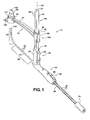
Figure 1 is a perspective view of a transurethral suprapubic cystostomy apparatus constructed in accordance with one presently preferred embodiment of the invention; -
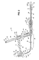
Figure 2 is a cross-sectional side view of the apparatus; -
Figure 3 is an enlarged cross-sectional side view of a rear handle of the apparatus ofFigure 1 ; -
Figure 4 is an enlarged fragmentary perspective view of a rear handle of the apparatus ofFigure 1 ; -
Figure 5 is an enlarged cross-sectional side view of a front handle shown in a locked position; -
Figure 6 is an enlarged cross-sectional side view of the front handle shown in an unlocked position; -
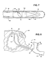
Figure 7 is an enlarged side view of a cutting tip attached to a collet of an advancement rod of the apparatus ofFigure 1 ; -
Figure 8 is a side view of a urethra and bladder showing a sound of the apparatus inserted therein; -
Figure 9 is a view similar toFigure 8 showing an alignment guide arm and capture cup of the apparatus positioned above an abdominal wall; -
Figure 10 is a side view showing the capture cup lowered into contact with the abdominal wall; -
Figure 11 is a side view showing a penetration depth marker of the apparatus moved adjacent an opening of the urethra; -
Figure 12 is a side view showing the cutting tip penetrating the bladder and abdominal wall; -
Figure 13 is a broken away side view showing the cutting tip fully penetrated through the bladder and abdominal wall and received in the capture cup; -
Figure 13A is an enlarged cross-sectional view of the capture cup showing the cutting tip attached to the advancement rod and captured in the capture cup; -
Figure 13B is an enlarged cross-sectional view of the capture cup showing the capture cup and the cutting tip removed from the advancement rod and captured in the capture cup; -
Figure 14 is a side view showing a catheter about to be attached to the sound via the collet of the advancement rod with the catheter drawn partially through the abdominal wall; -
Figure 14A is a perspective view of the catheter with a removal tool inserted therein; -
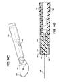
Figure 14B is an enlarged perspective view of a distal end of the catheter; -
Figure 14C is an enlarged perspective view of an end of the catheter with a shroud removed from the end; -
Figure 14D is an enlarged cross-sectional view of a drainage end of the catheter; -
Figure 14E is a view similar toFigure 14D with a removal tool inserted into the end; -
Figure 14F is a perspective view of the removal tool; -
Figure 15 is a view similar toFigure 14 showing the catheter drawn into the bladder and the alignment guide arm removed from the sound; -
Figure 16 is a view similar toFigure 15 showing a balloon of the catheter inflated; -
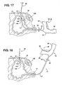
Figure 17 is a view similar toFigure 16 showing the inflated balloon drawn back into abutment with the bladder wall; and -
Figure 18 is a view similar toFigure 17 showing the catheter detached from the collet of the advancement rod and the sound being withdrawn from the urethra. - Referring in more detail to the drawings,
Figures 1 and2 illustrate a suprapubic transurethralcystostomy apparatus 10 constructed in accordance with one aspect of the invention. It should be recognized that other embodiments that perform a similar function, in a generally similar way, are contemplated to be within the scope of the invention. For example, theapparatus 10 and its associated individual components can be modified, while having a generally similar construction, and can be further modified to accommodate any size male or female, adult or pediatric patient, including obese and morbidly obese patients. Of course, it will be recognized by those skilled in the art that female and male organs, particularly the urethra, are shaped differently and have differing lengths and diameters, and so, the construction of theapparatus 10 can be varied to accommodate those differences. Theapparatus 10 includes an elongate hollow tubular body, generally referred to as asound 12, and an elongate positioning, referred to hereafter asalignment guide arm 14, adapted for operable attachment to the sound 12 in a predetermined position relative to thesound 12. Thesound 12 is configured for insertion through a urethra 16 into abladder 18, while thealignment guide arm 14 remains outside the patient to indicate the precise exit location of a trocar, referred to hereafter as cuttingtip 20, extending from a the sound 12 through anabdominal wall 22 of the patient. In addition to indicating the precise exit location of the cuttingtip 20 through theabdominal wall 22, thealignment guide ann 14 can be positioned to abut theabdominal wall 22 to provide a clamping action against theabdominal wall 22, thereby holding the instrument in place and providing tensile reinforcement of the patient's surface skin to allow thecutting tip 20 to cleanly pierce the skin as it extends outwardly through abdomen without stretching or tearing of the skin. As such, thealignment guide arm 14 allows the surgeon to readily identify the precise location of the cuttingtip 20 while in its blind location within thebladder 18, thereby enabling the surgeon to puncture a surgical pathway, referred to hereafter as anopening 24, through thebladder 18 and theabdomen wall 22 at a precise and intended location. Accordingly, the surgeon is provided with an increased level of confidence that theopening 24 formed by the cuttingtip 20 is at the desired location, will be clean without tearing, and is further assured that inadvertent damage to internal organs, such as the bowel, is avoided. Upon forming theopening 24, a catheter 26 (Figure 14 ) or other surgical instrument can be inserted through theopening 24 and into thebladder 18, depending on the nature of the procedure being performed. Further, thealignment guide ann 14 not only provides a precise exit location for the cuttingtip 20, but it can also be used to establish a precise linear path along which to form theopening 24 using an outside-in cut, such as by using an external trocar punch, for example, and extending the external trocar along a line established by thealignment guide arm 14, discussed further below. - As best shown in
Figures 1 and2 , thesound 12 has aproximal portion 28 and adistal portion 30, with thedistal portion 30 being configured for insertion into thebladder 18 through the urethra 16 (e.g.,Figure 8 ). Theproximal portion 28 and thedistal portion 30 have respective linear sections that are inclined relative to one another at a predetermined and generally fixed obtuse angle ofinclusion 32, such that the angle between the respective linear sections remains generally fixed in use. Theproximal portion 28 can have measuredindicator markings 33 to indicate to the surgeon the depth of insertion of the sound 12 into theurethra 16. In addition, a penetration depth marker, also referred to as anindicator slide 35 can be disposed on theproximal portion 28 to assist in identifying the depth and location of thesound 12 within thebladder 18 during the procedure. Thesound 12 is constructed from a material that can be readily sterilized, such as stainless steel, by way of example and without limitation. It should be recognized that other materials which can be readily sterilized are contemplated and incorporated herein within the scope of the invention, including plastics materials, for example. Thesound 12, although constructed from a material capable of being sterilized, is preferably constructed as a disposable, single use instrument. - The
proximal portion 28 is fixedly connected to afront handle 34 which has a straight,tubular body 36 extending rearwardly away from the sound 12 to anend 38. Thefront handle 34 provides a reliable and comfortable location for grasping and manipulating thesound 12. Thefront handle 34 can be provided having any suitable shape and configuration, depending on the requirements of the surgeon. For example, thefront handle 34 can be ergonomically designed for left and right handed physicians and designed for optimal manipulation, control and orientation of the sound 12 while preventing hand slippage when wet and in contact with surgical gloves. Accordingly, it is contemplated that thefront handle 34 can be provided having different shapes and contours, as desired. Thefront handle 34 andtubular body 36 can be molded as single piece halves and then subsequently joined, such as via fasteners, an adhesive or via welding, for example. Of course, thefront handle 34 andtubular body 36 can be formed using any suitable plastic or metal materials and processes. - The
front handle 34 has an upstanding housing, referred to hereafter asmount sleeve 40, configured for releasable attachment of a straight slide arm, referred to hereafter asmast 42, thereto. As best shown inFigure 2 , themount sleeve 40 has apocket 44 sized for close receipt of oneend 46 of themast 42 therein. To facilitate fixing theend 46 of the mast in thepocket 44, themount sleeve 40 has a releasablemast locking mechanism 48, represented here, by way of example and without limitation, as an over-centercam latch lever 50. Thecam latch lever 50 has acam surface 52 that frictionally engages themast 42 when thelever 50 is in a depressed, locked position, thereby maintaining themast 42 in a fixed position within thepocket 44. Otherwise, when thelever 50 is pivoted to a raised, unlocked position, thecam surface 52 is moved out of engagement with themast 42, thereby allowing themast 42 to be removed from thepocket 44. Thepocket 44 is configured to extend along a straight,linear axis 54, whereby themast 42, upon being locked within thepocket 44 also extends along theaxis 54. Theaxis 54 is oriented to extend substantially parallel to thedistal portion 30 of thesound 12. Accordingly, upon fixing themast 42 in themount sleeve 40, themast 42 and thedistal portion 30 of the sound 12 extend parallel or substantially parallel to one another. The angle of themast 42 extending from thefront handle 34 is configured to properly align thealignment guide arm 14 and acapture cup assembly 96 in the proper position to accept the cuttingtip 20. This is of great assistance to the surgeon, as the surgeon otherwise would not have a visual location of the cuttingtip 20 when inside thebladder 18. - As best shown in
Figures 5 and 6 , thefront handle 34 further includes a cuttingtip locking mechanism 56, represented here, by way of example and without limitation, as having a rotatable brake knob orwheel 58, acam member 60 fixed to thewheel 58 for conjoint rotation therewith, such as by being formed as a single piece of material therewith, and a spring member, referred to hereafter as abrake spring 62. When thewheel 58 is rotated to a locked position, the cuttingtip 20 is fixed against relative movement with thesound 12, and when rotated to an unlocked position, the cuttingtip 20 is movable relative to thesound 12, discussed further below. - The
tubular body 36 extends rear-ward from the rear of the front handle 34 a predetermined distance sufficient to provide the range of movement of the cuttingtip 20 desired. It should be recognized that the range of movement of the cuttingtip 20 will generally be less for a normal sized patient than for an obese or morbidly obese patient, and that the range of movement of the cuttingtip 20 can be provided to accommodate any size patient. Thetubular body 36 has tubular wall with anelongate slot 64 extending along its length, wherein the length of theslot 64 corresponds at least to the desired distance of travel of the cuttingtip 20. Theslot 64 is represented here as extending of the full length of thetubular body 36 along a bottom side thereof. The wall of thetubular body 36 is also represented, by way of example and without limitation, as having anupstanding rib 66 extending along an upper side of the wall diametrically opposite theslot 64. The upper side of the tubular wall preferably has measuredscale markings 67 to indicate to the surgeon the distance the cuttingtip 20 is extended, discussed further below. - The
apparatus 10 further includes anadvancement member 68, represented here as a flexible coil rod or flat spring member, with adistal end 70 being operably attached to the cuttingtip 20 and aproximal end 72 being attached to arear handle 74 of theapparatus 10. Thedistal end 70 is represented here as having aconnector 71 for selective, releasable attachment of the cuttingtip 20 thereto. As best shown inFigure 7 , theconnector 71 is a modified bayonet-type connector, for example, having at least one ramped, spiral shapedentry slot 73 terminating at a recessed lock detent. Theproximal end 72 is fixed to therear handle 74, such as by generallynarrow connector plate 78 sized to slide through theslot 64. Theconnector plate 78 can be fixed to theadvancement member 68, such as by a weld joint, for example, and to therear handle 74 via afastener 80, for example. Accordingly, movement of therear handle 74 causes conjoint movement of theconnector plate 78 and theadvancement member 68. - The
advancement member 68 can be provided of any suitable material flexible enough to traverse the bend in the sound 12 between theproximal portion 28 and thedistal portion 30, while being rigid enough to maintain a straight cutting path through thebladder 18 andabdominal wall 22, such as stainless steel or spring steel, for example. Theadvancement member 68 can further be provided as a single piece of material or multiple pieces of material joined to one another. Theadvancement member 68 has a plurality ofcircumferential notches 76 spaced in axially uniform relation from one another along a proximal or rear portion thereof for operable locking engagement with thebrake spring 62. Preferably, thenotches 76 extend over the full portion that traverses beneath the cuttingtip lock mechanism 56, thereby allowing the cuttingtip 20 to be locked in a fully retracted position and in a fully extended position, as well as over a plurality of locations between the fully retracted and extended positions. - The
rear handle 74 can be provided having any suitable shape and configuration. For example, therear handle 74 can be ergonomically designed for left and right handed physicians and designed for optimal manipulation, control and orientation of theadvancement member 68 and cuttingtip 20 while preventing hand slippage when wet and in contact with surgical gloves. Therear handle 74 can be molded as single piece halves, with the halves being subsequently joined, such as via fasteners, an adhesive or via welding, for example, and can be formed using any suitable plastic or metal materials and processes. As shown inFigures 2-4 , therear handle 74 is formed having a throughpassage 82 sized for close sliding receipt over thetubular body 36. Thepassage 82 can be provided with a recessednotch 84 sized to slidingly receive theupstanding rib 66 therein, thereby preventing rotation of therear handle 74 about thetubular body 36. This prevents unwanted rotation of the cuttingtip 20 while forming the opening through the tissue. - The
mast 42 has a straight,elongate body 86 extending between the end 46 received in thepocket 44 of thefront handle 34 and anopposite end 87. Thebody 86 preferably has measuredscale markings 88 to facilitate indicating to the surgeon the distance over which thecutting tip 20 generally needs to extend through the abdomen of the patient. Thebody 86 can be formed as a solid body or a hollowed body using any desired process, such as extrusion, for example, and can be formed of any suitable polymeric or metal material, as desired. Thebody 86 is represented here as being generally rectangular in lateral cross-section, which assists in maintaining thealignment guide arm 14 in its proper orientation by preventing unwanted relative pivoting between thearm 14 and thepositioning mast 42, although any cross-sectional geometry could be used. Thebody 86 can be provided of any suitable length, and preferably has a length between about 38-50 cm (15-20 inches), thereby allowing suitable adjustment of thealignment guide arm 14 on morbidly obese patients. - The
alignment guide arm 14 hasbody 90 that extends between afirst end 92 and asecond end 94. Thefirst end 92 is configured for operable attachment to theproximal portion 28 of thesound 12 and for sliding receipt along themast 42. Thesecond end 94 is configured for attachment to thecapture cup 96. Thefirst end 92 has a throughopening 98 configured for close sliding receipt of themast body 86. Accordingly, the throughopening 98 is shaped having a similar cross-sectional geometry as themast body 86, though being slightly larger to facilitate sliding movement along themast body 86. To facilitate releasable locking of thealignment guide arm 14 in a desired fixed position along themast body 86, thefirst end 92 has a releasablearm locking mechanism 100, represented here, by way of example and without limitation, as an over-centercam latch lever 102. Thecam latch lever 102 has acam surface 104 that frictionally engages themast 42 when thelever 102 is in a depressed, locked position, thereby maintaining thealignment guide arm 14 in a fixed position along themast body 86 at the desired position. Otherwise, when thelever 102 is pivoted to a raised, unlocked position, thecam surface 104 is moved out of engagement with themast body 86, thereby allowing thealignment guide arm 14 to be slid freely along the length of themast body 86. - The
second end 94 of thealignment guide arm 14 has a semi-annular orannular housing 106 providing a throughpassage 108 of a predetermined diameter that extends along anaxis 110 that is coaxial with thedistal portion 30 of the sound 12 when thenalignment guide arm 14 is attached to themast 42, and themast 42 is received in themount sleeve 40. Thehousing 106 is further represented here, by way of example and without limitation, as having an upper surface with one or morelateral slots 112 configured to releasably receive thecapture cup 96. As shown inFigure 13A , to facilitate guiding the cuttingtip 20 into thecapture cup 96, the throughpassage 108 of thehousing 106 can be provided having a funnel shape with anenlarged diameter 114 located adjacent a bottom surface of thehousing 106 and areduced diameter 116 located adjacent the upper surface of thehousing 106. - The
capture cup 96 has a closedupper portion 118 configured to be easily grasped and rotated, and is represented here, by way of example and without limitation, as having a generally rectangular wall with opposite sides easily graspable between a thumb and index finger. As best shown inFigures 13A and 13B , a generally cylindrical,annular wall 120 depends from theupper portion 118, wherein theannular wall 120 is sized for close sliding receipt in thehousing 106 of thealignment guide arm 14. Further, as shown inFigures 1 and9-13 , thecapture cup 96 has one ormore fingers 122 extending laterally outwardly for sliding receipt in theslots 112 of thehousing 106. Thefingers 122 extend outwardly to engage the upper surface of thehousing 106, and are received in theslots 112 by rotating thecapture cup 96 relative to thehousing 106. Accordingly, upon rotating thecapture cup 96 in one direction, thefingers 122 slide in theslots 112 and engage a bottom surface of theslots 112, wherein thecapture cup 96 is releasably locked to the housing 1065 and upon rotating thecapture cup 96 in the opposite direction, thefingers 122 exit theslots 112, wherein thecapture cup 96 can be removed from the housing. - To facilitate capturing the cutting
tip 20 in thecapture cup 96, a bore or cavity of thecapture cup 96 can be provided with an annular elastomeric wall orsleeve 124, such as an silicone tubing, for example, wherein thesleeve 124 has a slightly reduced diameter from the outer periphery of the cuttingtip 20 to cause the cuttingtip 20 to cut into thesleeve 124 upon being inserted therein, thereby being captured within thecapture cup 96 for hands free disposal. To provide assurance that the cuttingtip 20 in fully inserted in thecapture cup 96, astop surface 125 can be provided to abut the cuttingtip 20, thereby acting as a positive stop to limit the distance the cuttingtip 20 can be inserted into thecapture cup 96. Although thecapture cup 96 is shown having thefingers 122 for releasable receipt in theslots 112, other attachment mechanisms are contemplated herein, such as a threaded attachment or the capture cup could be formed as a single piece of material with thealignment guide arm 14. To further facilitate releasing the cuttingtip 20, a plurality of ribs can extend radially inwardly from the inner surface of thesleeve 124 to provide a bearing surface against the flat cutting blade as a 'stop' when rotating thecapture cup 96. This further assures the cuttingtip 20 will be rotated conjointly with thecapture cup 96 while rotating thecapture cup 96. - As best shown in
Figures 7 ,13A and 13B , the cuttingtip 20 is constructed having ametal cutting member 126 and aconnector 128 depending therefrom. The cuttingmember 126 is illustrated as having one ormore openings 130 to facilitate attachment of the cuttingmember 126 to theconnector 128. Theconnector 128 can be formed of an polymeric material, and further, can be molded, such as in an injection molding process, for example, to the cuttingmember 126. Theconnector 128 has a corresponding number of bayonets orfingers 132 extending laterally outwardly for sliding receipt in the rampedslots 73 in theconnector 71. Thefingers 132 are configured to lock releasably in theslots 73 by deflecting into recessed detents at the end of the rampedslots 73, and to deflect out of the detents upon applying a suitable torque to the cuttingmember 126, which can be applied via rotation of thecapture cup 96 when the cuttingtip 20 is captured therein. The cuttingtip 20 can be initially enclosed within acounterbore 133 in the distal end of thesound 12 and/or covered by a relativelysoft sheath 134, such as a soft polymeric material attached in flush relation on a reducedouter diameter portion 135 of the distal end portion, e.g. rubber or silicone, to protect the cutting blades of the cuttingmember 126 and to prevent the inadvertent cutting of tissue while inserting the sound 12 through theurethra 16. Upon moving the cuttingtip 20 axially outwardly from thesound 12, the cuttingtip 20 can readily penetrate the relatively soft sheath to expose the cuttingtip 20 for penetrating through thebladder 18 and out theabdomen wall 22. - As shown in
Figure 14A , thecatheter 26 has afirst end 136 configured for operable attachment to thesound 12 via theconnector 71 on theadvancement member 68 and asecond end 138 configured for operable attachment to a fluid collection system. As best shown inFigure 14C , thefirst end 136 has a bayonet-type connector 140 configured generally the same as theconnector 128 on the cuttingtip 20, thereby being attachable and removable via relative rotation, however, as shown inFigure 14D , the rear of theconnector 140 has a non-circular pocket, such as asquare pocket 141, for example. Thepocket 141 facilitates removing thecatheter 26 from theconnector 71 of theadvancement member 68 via aremove tool 143 having a appropriately shaped removal rod end 145 (Figure 14E ) conforming to the shape of thepocket 141. Accordingly, therod end 145 here has a square cross-sectional shape. To prevent inadvertent harm to tissue from theconnector 140, ashroud 142 is attached to theend 136 of thecatheter 26, with theshroud 142 overlying theconnector 140 to provide a substantially smooth and soft outer surface about theconnector 140. Anannular space 143 is provided between theconnector 140 and theshroud 142 to allow theconnector 71 on theadvancement member 68 to be received for attachment to theconnector 140 on thecatheter 26. Thecatheter 26 has aninflatable balloon 144 near thefirst end 136 to selectively maintain thecatheter 26 within thebladder 18, and at least oneopening 146, represented here by way of example and without limitation as being oval, between theballoon 144 and thefirst end 136 to provide entry for fluid into thecatheter 26 for drainage of the fluid within thebladder 18 through thecatheter 26. In addition, thecatheter 26 is adapted for releasable attachment of atether 148 thereto, wherein thetether 148 can be provided as a loop of suture material, for example. - As shown in
Figure 8 , the inside-out suprapubic transurethral procedure is initiated by inserting thedistal portion 30 of the sound 12 through theurethra 16 and into thebladder 18. During insertion of the sound 12 through theurethra 16, the cuttingtip 20 is covered with thesheath 134 to prevent inadvertent damage from occurring to theurethra 16. Themast 42 can be inserted and locked in themount sleeve 40 and thealignment guide arm 14 can be slid onto themast 42 and temporarily locked in the desired position via themast locking mechanism 48. - With the
alignment guide arm 14 positioned over theabdominal wall 22, an outside-in procedure could be performed, if desired, given thealignment guide arm 14 provides a path directly into thebladder 18. Accordingly, an external trocar punch could be pushed along theaxis 110 indicated by thehousing 106 through theabdominal wall 22 and into thebladder 18. Otherwise, if performing an inside-out procedure, thecapture cup 96 is attached to thehousing 106, and the tip or free end of thedistal portion 30 is positioned against the inside surface of thebladder 18, generally about 1-2 finger widths above apubic bone 152, to establish a slight "tenting" of thebladder 18 andabdominal wall 22, as shown inFigure 9 . The tenting facilitates moving the bowel away from thedistal portion 30 of the sound 12, and thus, away from the cuttingtip 20. With the exception of obese to morbidly obese patients, the tenting is generally observable externally by the surgeon. - Next, as shown in
Figure 10 , thealignment guide arm 14 can be released from the locked position on themast 42 and lowered into compressing engagement with the outer skin surface of theabdominal wall 22. With thehousing 106 of thealignment guide arm 14 properly positioned against theabdomen wall 22, themast locking mechanism 48 can again be locked, thereby maintaining theapparatus 10 in the desired position. - Then, as shown in
Figure 11 , upon locking thealignment guide arm 14 in the desired location over theabdomen wall 22, thepenetration depth marker 35 can be moved forward to the opening of the urethra 16 to prevent further movement of thesound 12. The measurement orindicator markings 33 can be observed by the physician. - Next, as shown in
Figure 12 , the cuttingtip 20 can be advanced to penetrate through theprotective sheath 134, through thebladder 18 and through theabdominal wall 22. This is performed by rotating thewheel 58 of the cuttingtip locking mechanism 56 from the locked position to the unlocked position, thereby biasing thebrake spring 62 out of engagement with therespective notch 76 in theadvancement member 68. Accordingly, theadvancement member 68 is free to slide within thetubular body 36 and the sound 12 upon pushing on therear handle 74. As therear handle 74 is pushed, the surgeon is able to visually see from the scaledmarkings 67 on thetubular body 36 how far theadvancement member 68, and thus, the cuttingtip 20, is being advanced. In addition, the surgeon can readily determine an indication of the distance from the inside of thebladder wall 18 to the outside of theabdomen wall 22 via the measuredmarkings 88 on the mast, and thus, the surgeon knows generally how far the cuttingtip 20 must be advanced to penetrate theabdomen wall 22. While being advanced outwardly from thesheath 134 and outwardly, away from thesound 12, theadvancement member 68 remains rigid along the length extended away from the sound 12 to allow it to penetrate theabdomen wall 22 in a controlled and substantially straight path such that it remains in constant coaxial alignment with thehousing 106 of thealignment guide arm 14 and thecapture cup 96. - As shown in
Figures 13 and13A , the cuttingtip 20 is then advanced into and captured in thecapture cup 96 of thealignment guide arm 14, whereupon the cuttingtip 20 can be released in a hands-free procedure and then disposed as captured in the capture cup 96 (Figure 13B ). - As shown in
Figure 13B , upon the cuttingtip 20 being captured in thereceptacle 96 and released from thesound 12, thealignment guide arm 14 can then be detached from themount sleeve 40. Then, as shown inFigure 14 , theend 136 of thecatheter 26 can be attached to theconnector 71 on the end of theadvancement member 68. As shown inFigure 15 , with thecatheter 26 operably attached to thesound 12 via theadvancement member 68, thecatheter 26 can be pulled into the bladder by withdrawing the sound 12 from theurethra 16 and/or by withdrawing theadvancement member 68 via pulling on therear handle 74. Thedepth marker 35 on the sound 12 located at the opening of the urethra 16 can assist the surgeon in identifying how far the sound 12 needs to be withdrawn in order to ensure theend 136 andballoon 144 ofcatheter 26 are located sufficiently within thebladder 18 prior to inflating theballoon 144. - As shown in
Figure 16 , with thesound 12 and/oradvancement member 68 having been drawn a sufficient distance outwardly from the urethra 16 to ensure thecatheter 26 is received properly in thebladder 18, as noted by the distance between the urethra opening and thepenetration depth marker 35, theballoon 144 of thecatheter 26 is inflated with fluid via thesyringe 88 at or adjacent to thesecond end 84 of thecatheter 26. - As shown in
Figure 17 , theinflated balloon 144 is then manipulated into seated engagement with the surgically cut opening in thebladder 18 by pulling or otherwise withdrawing thecatheter 26 slightly outwardly from theabdominal wall 22, while still attached to theadvancement member 68. - Then, as shown in
Figure 18 , once the surgeon has verified that theballoon 144 is properly seated against the inner surface of thebladder wall 18, and that proper drainage is flowing through thecatheter 26,catheter 26 is detached from theadvancement member 68, and thesound 12 is then gently withdrawn from theurethra 16. As discussed above, the detachment of thecatheter 26 from theadvancement member 68 is facilitated by use of theremoval tool 143. By inserting the rod of theremoval tool 143 through the length of thecatheter 26, and inserting the appropriately configuredrod end 145 into thepocket 141 of theconnector 140, theremoval tool 143 can be rotated in the counter-clockwise direction to impart relative rotation between theconnectors connectors bladder 18. Meanwhile, though thesound 12 andadvancement member 68 are free for removal through theurethra 16, thecatheter 26 remains partially deployed in thebladder 18 with theballoon 144 in seated engagement with the inner surface of thebladder wall 18. - Obviously, many modifications and variations of the present invention are possible in light of the above teachings. It is, therefore, to be understood that within the scope of the appended claims, the invention may be practiced otherwise than as specifically described.
Claims (15)
- A suprapubic transurethral cystostomy apparatus (10) for forming a surgical opening (24) through an abdominal wall (22) into a bladder (18), comprising:an elongate tubular body (12) having a length including a proximal portion (28) and a distal portion (30) inclined relative to one another, the distal portion (30) extending along an axis (110) to an end of the distal portion (30), the distal portion configured for insertion through a urethra (16) into the bladder (18); and characterized byan elongate arm (14) having a first end (92) operably attached to the proximal portion (28) of the tubular body (12) and a second end (94) providing an indicator (106) aligned coaxially with the axis (110) of the distal portion (30); and wherein:the tubular body (12) and the elongate arm 14 are operatively attached to locate the end of the distal portion (30) within the bladder (18), and to locate the indicator (106) exteriorly of the abdominal wall (22), and to maintain the end of the distal portion (30) and the indicator (106) in coaxial relationship to the axis (110) over a range of movement of the indicator (106) relative to the end of the distal portion (30) to accommodate abdominal walls having different thicknesses;the distal portion (30) of the tubular body (12) is moveable within the bladder (18) by manipulation of the proximal portion (28) of the tubular body outside of the urethra (16); andthe end of the distal portion (30) and the indicator (106) establish a linear path along the axis (110) for the surgical opening (24) through the abdominal wall (22) into the bladder (18).
- The apparatus of claim 1 further including an elongate advancement member (68) slidably received through the tubular body (12) and a cutting tip (20) attached to an end (70) of the advancement member (68) for forming the surgical opening (24) upon advancement of the advancement member (68) from the end of the distal portion (30) to the indicator (106).
- The apparatus of claim 2 further including a cup (96) releasably attachable to the indicator (106), the cup (96) having a cavity aligned with the axis (110) to receive the cutting tip (20) therein.
- The apparatus of claim 3 wherein the cavity has an elastomeric wall (124) into which the cutting tip (20) cuts to capture and hold the cutting tip (20) within the cavity.
- The apparatus of claims 3 or 4 wherein an inwardly-converging funnel shaped structure (114, 116) is located at the second end (94) of the elongate arm (14) to guide the cutting tip (20) into the cavity of the cup (96).
- The apparatus of any one of claims 3-5 wherein the cutting tip (20) is releaseable from the end (70) of the advancement member (68) with rotational movement, the cup (96) is releaseable from the indicator (106) with rotational movement, and the cutting tip (20) releases from the end (70) of the advancement member 68) conjointly with the cup (96) releasing from the indicator (106) with rotational movement of the cup (96) relative to the indicator (106).
- The apparatus of any one of claims 2-6 further comprising a catheter (26) having a catheter end (136) adapted to connect to the end (70) of the advancement member (68) in place of the cutting tip (20).
- The apparatus of claim 7 wherein retraction of the advancement member (68) in the tubular body (12) draws the connected catheter end (136) into contact with the end of the distal portion (30) of the tubular body (12).
- The apparatus of any one of claims 6-8 wherein the catheter end (136) and the end (70) of the advancement member (68) are connected by a separable connector (71, 140).
- The apparatus of claim 9 further comprising a tool (143) inserted through the catheter (26) to contact the separable connector (71, 140) and disconnect the catheter end (136) of the catheter (26) from the end (70) of the advancement member (68).
- The apparatus of any one of claims 6-10 wherein the end (70) of the advancement member (68) includes a bayonet type connector (71) which is connectable to either a complementary bayonet type connector (128) of the cutting tip (20) or to a complementary bayonet type connector (140) of the catheter (126).
- The apparatus of any one of claims 1-11 further including a straight mast (42) attached to the proximal portion (28) of the tubular body (12), the elongate arm (14) connected to slide along the mast (42) with the indicator (106) remaining coaxially aligned with the axis (110).
- The apparatus of claim 12, wherein the mast (42) includes markings (88) which indicate the distance which the cutting tip (20) must advance from the end of the distal portion (30) of the tubular body (12) to the indicator (106) to form the surgical opening, and the proximal portion (28) of the tubular body (12) includes markings (33) which indicate a distance of insertion of the distal portion (30) of the tubular body (12) into the urethra (16), and markings (67) associated with the advancement member (68) which indicate the extent of advancement of the cutting tip (20) from the end of the distal portion (30) of the tubular body (12).
- The apparatus of any one of claims 2-13 further including a locking mechanism (56) movable between a locked position to prevent relative movement between the advancement member (68) and the tubular body (12) and an unlocked position to allow relative sliding movement between the advancement member (68) and the tubular body (12).
- The apparatus of any one of claims 2-14 wherein the cutting tip (20) is initially positionable at a withdrawn position within the end of the distal portion (30) of the tubular body (12), the end of the distal portion (30) of the tubular body (12) is initially covered by a sheath (134) to enclose the cutting tip (20) within the end of the distal portion (30) of the tubular body (12) for insertion of the distal portion (30) through the urethra (16), and the sheath (134) is formed from a material which permits the cutting tip (20) to penetrate through the sheath (134) to expose the cutting tip (20) upon advancement of the advancement member (68) to extend cutting tip (20) from the withdrawn position outwardly from the end of the distal portion (30) of the tubular body (12).
Applications Claiming Priority (4)
| Application Number | Priority Date | Filing Date | Title |
|---|---|---|---|
| US97554807P | 2007-09-27 | 2007-09-27 | |
| US3845708P | 2008-03-21 | 2008-03-21 | |
| US12/238,941 US8118826B2 (en) | 2007-09-27 | 2008-09-26 | Method of performing a suprapubic transurethral cystostomy and associated procedures and apparatus therefor |
| PCT/US2008/078053 WO2009042985A2 (en) | 2007-09-27 | 2008-09-29 | Method of performing a suprapubic transurethral cystostomy and associated procedures and apparatus therefor |
Publications (3)
| Publication Number | Publication Date |
|---|---|
| EP2197356A2 EP2197356A2 (en) | 2010-06-23 |
| EP2197356A4 EP2197356A4 (en) | 2011-10-05 |
| EP2197356B1 true EP2197356B1 (en) | 2014-04-09 |
Family
ID=40509143
Family Applications (2)
| Application Number | Title | Priority Date | Filing Date |
|---|---|---|---|
| EP08834232.4A Active EP2197356B1 (en) | 2007-09-27 | 2008-09-29 | Apparatus for a suprapubic transurethral cystostomy |
| EP08833618.5A Active EP2195066B1 (en) | 2007-09-27 | 2008-09-29 | Method of accessing a bladder and associated apparatus therefor |
Family Applications After (1)
| Application Number | Title | Priority Date | Filing Date |
|---|---|---|---|
| EP08833618.5A Active EP2195066B1 (en) | 2007-09-27 | 2008-09-29 | Method of accessing a bladder and associated apparatus therefor |
Country Status (5)
| Country | Link |
|---|---|
| US (3) | US8118826B2 (en) |
| EP (2) | EP2197356B1 (en) |
| JP (2) | JP5385905B2 (en) |
| CN (2) | CN101820821B (en) |
| WO (2) | WO2009042985A2 (en) |
Families Citing this family (36)
| Publication number | Priority date | Publication date | Assignee | Title |
|---|---|---|---|---|
| US20050143690A1 (en) | 2003-05-01 | 2005-06-30 | High Kenneth A. | Cystotomy catheter capture device and methods of using same |
| US8382785B2 (en) * | 2007-09-27 | 2013-02-26 | Swan Valley Medical Incorporated | Apparatus and method for performing cystotomy procedures |
| US8118826B2 (en) | 2007-09-27 | 2012-02-21 | Swan Valley Medical, Incorporated | Method of performing a suprapubic transurethral cystostomy and associated procedures and apparatus therefor |
| SE532142C2 (en) * | 2007-09-28 | 2009-11-03 | Clinical Laserthermia Systems | Device for determining a thermal property of a tissue |
| US8262632B2 (en) * | 2009-04-07 | 2012-09-11 | Robert Branch Faber | Female urinary catheterization device |
| US9108020B1 (en) | 2010-09-03 | 2015-08-18 | Michael Feloney | Female urethral catheterization device |
| US8998883B1 (en) * | 2010-09-03 | 2015-04-07 | Michael Feloney | Female urethral catheterization assisting device |
| US9271754B2 (en) | 2010-12-16 | 2016-03-01 | Boston Scientific Scimed, Inc. | Movable curved needle for delivering implants and methods of delivering implants |
| US9381075B2 (en) | 2011-01-31 | 2016-07-05 | Boston Scientific Scimed, Inc. | Deflection member for delivering implants and methods of delivering implants |
| DE102011007121A1 (en) * | 2011-04-11 | 2012-10-11 | Karl Storz Gmbh & Co. Kg | Handling device for a micro-invasive-surgical instrument |
| US8845657B2 (en) * | 2011-05-24 | 2014-09-30 | Covidien Lp | Surgical support assembly |
| US9345472B2 (en) | 2011-09-02 | 2016-05-24 | Boston Scientific Scimed, Inc. | Multi-arm tool for delivering implants and methods thereof |
| US20140058446A1 (en) * | 2011-09-28 | 2014-02-27 | Avi Bernstein | Spinal implant system |
| US9226771B2 (en) * | 2012-08-24 | 2016-01-05 | Tycast Technologies, Llc | Medical device for providing port-like access to a mammalian urinary system and methods of inserting an utilizing the same |
| US9271752B2 (en) * | 2013-03-13 | 2016-03-01 | Swan Valley Medical Incorporated | Method and apparatus for placing a cannula in a bladder |
| EP2967967B1 (en) * | 2013-03-15 | 2019-09-25 | Griffith, Donald | Systems and methods for microbial resistance zones |
| WO2014162430A1 (en) * | 2013-04-01 | 2014-10-09 | テルモ株式会社 | Puncture device |
| WO2015020953A1 (en) * | 2013-08-05 | 2015-02-12 | Darin Schaeffer | Medical devices having a releasable tubular member and methods of using the same |
| CN105578976B (en) * | 2013-09-27 | 2018-09-18 | 奥林巴斯株式会社 | Contact unit, processing utensil and processing system |
| WO2015054370A1 (en) | 2013-10-08 | 2015-04-16 | Cook Medical Technologies Llc | Device for external percutaneous connections |
| BR112016015419B1 (en) * | 2013-12-30 | 2022-02-08 | Medi-Tate Ltd | INCISION IMPLANT FOR THE CREATION OF INCISIONS IN THE PROSTATIC URETHRA OF A SUBJECT |
| CN104906682A (en) | 2014-01-24 | 2015-09-16 | 史蒂文·沙勒布瓦 | Articulating balloon catheter and method for using the same |
| US9974563B2 (en) | 2014-05-28 | 2018-05-22 | Cook Medical Technologies Llc | Medical devices having a releasable member and methods of using the same |
| US9913661B2 (en) | 2014-08-04 | 2018-03-13 | Cook Medical Technologies Llc | Medical devices having a releasable tubular member and methods of using the same |
| US9603593B2 (en) * | 2014-09-30 | 2017-03-28 | Coloplast A/S | Needle handling device and a method for implanting a penile prosthetic insert |
| US10695089B2 (en) | 2015-07-10 | 2020-06-30 | Medtronic, Inc. | Medical tools and methods for gaining access to extravascular spaces |
| AU2017305440B2 (en) | 2016-08-03 | 2019-11-07 | Teleflex Medical Incorporated | Surgical ligation clip |
| US12023041B2 (en) | 2017-03-21 | 2024-07-02 | Teleflex Medical Incorporated | Clip applier |
| CN110740695A (en) | 2017-03-21 | 2020-01-31 | 泰利福医疗公司 | Surgical clip and clip applier |
| US11266408B2 (en) | 2017-03-21 | 2022-03-08 | Teleflex Medical Incorporated | Clip applier having stabilizing member |
| US11534177B2 (en) | 2017-03-21 | 2022-12-27 | Teleflex Medical Incorporated | Flexible stabilizing member for a clip applier |
| AU2018290343B2 (en) | 2017-06-22 | 2020-11-26 | Teleflex Medical Incorporated | Surgical clip |
| EP3709900B1 (en) | 2017-11-14 | 2024-04-10 | Teleflex Medical Incorporated | Surgical clip |
| JP2023507792A (en) | 2019-12-19 | 2023-02-27 | テレフレックス メディカル インコーポレイテッド | surgical clip |
| KR102563848B1 (en) * | 2021-02-04 | 2023-08-07 | 전북대학교산학협력단 | Trocar device for bladder puncture |
| US20220395289A1 (en) * | 2021-05-25 | 2022-12-15 | Swan Valley Medical Incorporated | Optically guided suprapubic cystostomy |
Family Cites Families (89)
| Publication number | Priority date | Publication date | Assignee | Title |
|---|---|---|---|---|
| US84815A (en) | 1868-12-08 | Improved instrument for treating fistula | ||
| US3241554A (en) | 1963-08-14 | 1966-03-22 | Baxter Don Inc | Peritoneal dialysis entry device |
| US3640281A (en) | 1970-01-02 | 1972-02-08 | Jack R Robertson | Method of inserting a suprapubic catheter |
| US3656486A (en) | 1970-04-08 | 1972-04-18 | Jack R Robertson | Instrument for inserting a suprapubic catheter |
| US3924633A (en) | 1974-01-31 | 1975-12-09 | Cook Inc | Apparatus and method for suprapubic catheterization |
| US3920023A (en) | 1974-03-21 | 1975-11-18 | Kendall & Co | Method and apparatus for placement of a suprapubic catheter |
| US4875897A (en) | 1981-06-12 | 1989-10-24 | Regents Of University Of California | Catheter assembly |
| DE3211576C2 (en) | 1982-03-29 | 1984-04-12 | Hans Georg Prof. Dr. 4040 Neuss Bender | Device for drainage of the urinary bladder |
| EP0127261A1 (en) | 1983-03-30 | 1984-12-05 | Vance Products Incorporated | Method for providing percutaneous communication with the renal or ureteral cavities |
| US4557255A (en) | 1983-08-22 | 1985-12-10 | Goodman Tobias M | Ureteroscope |
| US4676780A (en) | 1986-02-21 | 1987-06-30 | Hans Lee | Surgical apparatus for performing suction lipectomy |
| US4596553A (en) | 1984-05-07 | 1986-06-24 | Hans Lee | Method and apparatus for performing suction lipectomy |
| US4627834A (en) | 1984-05-07 | 1986-12-09 | Hans Lee | Apparatus for performing suction lipectomy |
| GB8424436D0 (en) | 1984-09-27 | 1984-10-31 | Pratt Int Ltd Burnerd | Surgical appliance |
| US4739751A (en) * | 1986-10-03 | 1988-04-26 | Temple University | Apparatus and method for reconstructive surgery |
| US4995868A (en) | 1988-10-12 | 1991-02-26 | Bard Limited | Catheter |
| US4899733A (en) | 1988-12-19 | 1990-02-13 | Blackstone Ultrasonic, Inc. | Device and technique for transurethral ultrasonic lithotripsy using a flexible ureteroscope |
| DE3919740A1 (en) | 1989-06-16 | 1990-12-20 | Dimitrov Pentcho | Bladder fistula prodn. instrument - has inflatable balloon attached to end of catheter |
| US5059183A (en) | 1989-09-01 | 1991-10-22 | Neal Semrad | Stop guide wire and double ended obturator-catheter-sheath system and method of use of same |
| US5330497A (en) | 1989-11-22 | 1994-07-19 | Dexide, Inc. | Locking trocar sleeve |
| US5232451A (en) | 1989-11-22 | 1993-08-03 | Dexide, Inc. | Locking trocar sleeve |
| US5019032A (en) | 1990-04-03 | 1991-05-28 | Robertson Jack R | Refined suspension procedure with implement for treating female stress incontinence |
| US5290294A (en) | 1990-04-17 | 1994-03-01 | Brian Cox | Method and apparatus for removal of a foreign body cavity |
| WO1992008513A1 (en) | 1990-11-20 | 1992-05-29 | Interventional Thermodynamics, Inc. | Tension guide and dilator |
| US5183464A (en) | 1991-05-17 | 1993-02-02 | Interventional Thermodynamics, Inc. | Radially expandable dilator |
| US5334185A (en) | 1991-06-28 | 1994-08-02 | Giesy Consultants, Inc. | End-to-end instrument placement apparatus |
| US5152749A (en) * | 1991-06-28 | 1992-10-06 | American Medical Systems, Inc. | Instrument placement apparatus |
| US5203773A (en) | 1991-10-18 | 1993-04-20 | United States Surgical Corporation | Tissue gripping apparatus for use with a cannula or trocar assembly |
| US5232440A (en) | 1992-02-26 | 1993-08-03 | Wilk Peter J | Method and device for draining abscess |
| US5509900A (en) | 1992-03-02 | 1996-04-23 | Kirkman; Thomas R. | Apparatus and method for retaining a catheter in a blood vessel in a fixed position |
| US5707362A (en) * | 1992-04-15 | 1998-01-13 | Yoon; Inbae | Penetrating instrument having an expandable anchoring portion for triggering protrusion of a safety member and/or retraction of a penetrating member |
| NL9201118A (en) | 1992-06-24 | 1994-01-17 | Leuven K U Res & Dev | TOOL KIT FOR LAPAROSCOPIC VAGINAL HYSTERECTOMY. |
| US5232443A (en) | 1992-07-17 | 1993-08-03 | Leach Gary E | Combined urological retractor and instrument for inserting suprapubic catheter and method of use |
| US5667488A (en) | 1992-08-12 | 1997-09-16 | Vidamed, Inc. | Transurethral needle ablation device and method for the treatment of the prostate |
| US5356382A (en) | 1992-10-23 | 1994-10-18 | Applied Medical Research, Inc. | Percutaneous tract measuring and forming device |
| US5275166A (en) | 1992-11-16 | 1994-01-04 | Ethicon, Inc. | Method and apparatus for performing ultrasonic assisted surgical procedures |
| US6576008B2 (en) | 1993-02-19 | 2003-06-10 | Scimed Life Systems, Inc. | Methods and device for inserting and withdrawing a two piece stent across a constricting anatomic structure |
| US5431676A (en) * | 1993-03-05 | 1995-07-11 | Innerdyne Medical, Inc. | Trocar system having expandable port |
| US5348541A (en) | 1993-05-05 | 1994-09-20 | Lyell Mark S | Suprapubic catheter placement apparatus (lyell sound) |
| CA2141023C (en) | 1993-05-28 | 2002-07-30 | Larry A. Eld | Percutaneous gastrostomy feeding tube applicator and method |
| US5304119A (en) | 1993-06-24 | 1994-04-19 | Monsanto Company | Instrument for injecting implants through animal hide |
| EP0643980B1 (en) | 1993-09-21 | 1998-12-30 | United States Surgical Corporation | Surgical instrument for expanding body tissue |
| US5546958A (en) | 1994-03-31 | 1996-08-20 | Lake Region Manufacturing Company, Inc. | Guidewire extension system with tactile connection indication |
| US6162236A (en) | 1994-07-11 | 2000-12-19 | Terumo Kabushiki Kaisha | Trocar needle and expandable trocar tube |
| US5490845A (en) | 1994-09-20 | 1996-02-13 | Racz; Gabor J. | R-X safety catheter |
| DE69601437T2 (en) | 1995-04-21 | 1999-09-30 | Bard Inc C R | Interlocking catheter unit |
| US5857999A (en) | 1995-05-05 | 1999-01-12 | Imagyn Medical Technologies, Inc. | Small diameter introducer for laparoscopic instruments |
| US5772678A (en) | 1995-10-20 | 1998-06-30 | Inlet Medical, Inc. | Retractable disposable tip reusable trocar obturator |
| CN2247003Y (en) * | 1995-12-21 | 1997-02-12 | 钱抚生 | External sleeve separating type needle for vesicopuncture fistulation |
| US5827319A (en) | 1996-05-20 | 1998-10-27 | Innerdyne, Inc. | Radially expandable access system having disposable and reusable components |
| US5935107A (en) | 1996-10-07 | 1999-08-10 | Applied Medical Resources Corporation | Apparatus and method for surgically accessing a body cavity |
| US5843113A (en) | 1996-10-08 | 1998-12-01 | High; Kenneth | Endocystotomy tool |
| US6099547A (en) * | 1997-02-13 | 2000-08-08 | Scimed Life Systems, Inc. | Method and apparatus for minimally invasive pelvic surgery |
| DE69821127T2 (en) | 1997-02-13 | 2004-06-09 | Boston Scientific Ltd., St. Michael | PERCUTANEOUS AND HIATAL DEVICES FOR USE IN MINIMALLY INVASIVE PELVIC SURGERY |
| GB9707997D0 (en) | 1997-04-21 | 1997-06-11 | Walker Justin R A | Surgical implement |
| US5836913A (en) | 1997-05-02 | 1998-11-17 | Innerdyne, Inc. | Device and method for accessing a body cavity |
| DE69837611T2 (en) | 1997-10-01 | 2007-12-27 | Boston Scientific Ltd., St. Michael | dilation |
| US6796976B1 (en) | 1998-03-06 | 2004-09-28 | Scimed Life Systems, Inc. | Establishing access to the body |
| US6245052B1 (en) | 1998-07-08 | 2001-06-12 | Innerdyne, Inc. | Methods, systems, and kits for implanting articles |
| US6187000B1 (en) | 1998-08-20 | 2001-02-13 | Endius Incorporated | Cannula for receiving surgical instruments |
| US6030393A (en) | 1998-09-15 | 2000-02-29 | Corlew; Earvin L. | Needle and procedure for relieving urinary incontinence |
| US6752813B2 (en) | 1999-04-09 | 2004-06-22 | Evalve, Inc. | Methods and devices for capturing and fixing leaflets in valve repair |
| US6632197B2 (en) | 1999-04-16 | 2003-10-14 | Thomas R. Lyon | Clear view cannula |
| US6629987B1 (en) | 1999-07-30 | 2003-10-07 | C. R. Bard, Inc. | Catheter positioning systems |
| US7398781B1 (en) * | 1999-08-10 | 2008-07-15 | Maquet Cardiovascular, Llc | Method for subxiphoid endoscopic access |
| US6436119B1 (en) | 1999-09-30 | 2002-08-20 | Raymedica, Inc. | Adjustable surgical dilator |
| US6524304B1 (en) | 1999-10-14 | 2003-02-25 | Scan Corporation | Apparatus and method for introducing one or more branch lines into IV tubing |
| US6547761B2 (en) | 2000-01-07 | 2003-04-15 | Scimed Life Systems, Inc. | Drainage catheter |
| US6319266B1 (en) | 2000-03-16 | 2001-11-20 | United States Surgical Corporation | Trocar system and method of use |
| US6596001B2 (en) * | 2000-05-01 | 2003-07-22 | Ethicon, Inc. | Aiming device for surgical instrument and method for use for treating female urinary incontinence |
| AU2001265005B2 (en) * | 2000-05-26 | 2005-11-03 | Fenwal, Inc. | Improved needle design and manufacturing method for medical applications |
| TW515949B (en) * | 2000-06-08 | 2003-01-01 | Via Tech Inc | Method for scheduling run sequence of read and write requests |
| ITBO20000511A1 (en) | 2000-09-05 | 2002-03-05 | Gianmario Monza | APPARATUS AND METHOD FOR THE CONSTRUCTION OF GASTROSTOMY |
| US7364541B2 (en) * | 2001-03-09 | 2008-04-29 | Boston Scientific Scimed, Inc. | Systems, methods and devices relating to delivery of medical implants |
| US6743207B2 (en) | 2001-04-19 | 2004-06-01 | Scimed Life Systems, Inc. | Apparatus and method for the insertion of a medical device |
| US7179219B2 (en) | 2001-11-20 | 2007-02-20 | Ams Research Corporation | Incontinence treatment with urethral guide |
| WO2003088833A1 (en) | 2002-04-22 | 2003-10-30 | The Johns Hopkins University | Apparatus for insertion of a medical device during a medical imaging process |
| US7377897B1 (en) | 2002-05-02 | 2008-05-27 | Kunkel Sanford S | Portal device |
| US6932829B2 (en) | 2002-06-24 | 2005-08-23 | Cordis Corporation | Centering catheter |
| US20040127818A1 (en) * | 2002-12-27 | 2004-07-01 | Roe Steven N. | Precision depth control lancing tip |
| US20050171511A1 (en) | 2003-05-01 | 2005-08-04 | High Kenneth A. | Catheter capture device |
| US20050143690A1 (en) | 2003-05-01 | 2005-06-30 | High Kenneth A. | Cystotomy catheter capture device and methods of using same |
| US20050119685A1 (en) * | 2003-10-17 | 2005-06-02 | Smith Robert C. | Expandible surgical access device |
| US7338432B2 (en) * | 2003-11-17 | 2008-03-04 | Konstantin Valtchev | Urethral sling introducer and method of use |
| US7892203B2 (en) * | 2004-09-09 | 2011-02-22 | Onset Medical Corporation | Expandable transluminal sheath |
| ATE509085T1 (en) * | 2005-02-04 | 2011-05-15 | Lipid Nutrition Bv | METHOD FOR PRODUCING FATTY ACIDS |
| CN101378745A (en) * | 2006-02-08 | 2009-03-04 | 学校法人久留米大学 | Pharmaceutical composition comprising meglitinide for prevention of hepatic fibrosis |
| US8118826B2 (en) | 2007-09-27 | 2012-02-21 | Swan Valley Medical, Incorporated | Method of performing a suprapubic transurethral cystostomy and associated procedures and apparatus therefor |
| DE202008011708U1 (en) | 2008-09-03 | 2009-10-29 | Popp, Andreas | Suction catheter for the upper and lower airways |
-
2008
- 2008-09-26 US US12/238,941 patent/US8118826B2/en active Active
- 2008-09-26 US US12/239,129 patent/US8118736B2/en active Active
- 2008-09-29 CN CN2008801093241A patent/CN101820821B/en active Active
- 2008-09-29 EP EP08834232.4A patent/EP2197356B1/en active Active
- 2008-09-29 JP JP2010527228A patent/JP5385905B2/en active Active
- 2008-09-29 CN CN2008801093383A patent/CN101896219B/en active Active
- 2008-09-29 WO PCT/US2008/078053 patent/WO2009042985A2/en active Application Filing
- 2008-09-29 JP JP2010527229A patent/JP5501235B2/en active Active
- 2008-09-29 WO PCT/US2008/078062 patent/WO2009042988A2/en active Application Filing
- 2008-09-29 EP EP08833618.5A patent/EP2195066B1/en active Active
-
2012
- 2012-01-09 US US13/346,587 patent/US8574256B2/en active Active
Also Published As
| Publication number | Publication date |
|---|---|
| EP2195066A2 (en) | 2010-06-16 |
| EP2197356A2 (en) | 2010-06-23 |
| US20090088786A1 (en) | 2009-04-02 |
| US20120109175A1 (en) | 2012-05-03 |
| EP2195066B1 (en) | 2014-10-22 |
| JP2010540120A (en) | 2010-12-24 |
| WO2009042985A2 (en) | 2009-04-02 |
| JP2010540121A (en) | 2010-12-24 |
| WO2009042985A3 (en) | 2009-07-09 |
| EP2195066A4 (en) | 2012-03-21 |
| US8118736B2 (en) | 2012-02-21 |
| WO2009042988A2 (en) | 2009-04-02 |
| JP5385905B2 (en) | 2014-01-08 |
| CN101896219A (en) | 2010-11-24 |
| JP5501235B2 (en) | 2014-05-21 |
| US8574256B2 (en) | 2013-11-05 |
| US8118826B2 (en) | 2012-02-21 |
| CN101820821B (en) | 2012-02-01 |
| CN101820821A (en) | 2010-09-01 |
| CN101896219B (en) | 2012-08-22 |
| EP2197356A4 (en) | 2011-10-05 |
| WO2009042988A3 (en) | 2009-05-22 |
| US20090088599A1 (en) | 2009-04-02 |
Similar Documents
| Publication | Publication Date | Title |
|---|---|---|
| EP2197356B1 (en) | Apparatus for a suprapubic transurethral cystostomy | |
| EP1743365B1 (en) | Cystotomy catheter capture device | |
| CA1045493A (en) | Method and apparatus for placement of a suprapubic catheter | |
| US5334185A (en) | End-to-end instrument placement apparatus | |
| US5348541A (en) | Suprapubic catheter placement apparatus (lyell sound) | |
| JP7219425B2 (en) | Tools and methods for vaginal access | |
| EP0593569A1 (en) | Instrument placement apparatus | |
| WO2011149783A1 (en) | Apparatus for performing cystotomy procedures | |
| JP2002517263A (en) | Catheter introducer | |
| US11701143B2 (en) | Catheter devices, needle assemblies, kits and methods | |
| WO2023006071A1 (en) | Interventional catheter instrument | |
| US20120239070A1 (en) | Cutting needle for urological and other surgical procedures |
Legal Events
| Date | Code | Title | Description |
|---|---|---|---|
| PUAI | Public reference made under article 153(3) epc to a published international application that has entered the european phase |
Free format text: ORIGINAL CODE: 0009012 |
|
| 17P | Request for examination filed |
Effective date: 20100329 |
|
| AK | Designated contracting states |
Kind code of ref document: A2 Designated state(s): AT BE BG CH CY CZ DE DK EE ES FI FR GB GR HR HU IE IS IT LI LT LU LV MC MT NL NO PL PT RO SE SI SK TR |
|
| AX | Request for extension of the european patent |
Extension state: AL BA MK RS |
|
| RIN1 | Information on inventor provided before grant (corrected) |
Inventor name: KROEHL, PETE, W. Inventor name: BUREK, PAUL, P. Inventor name: WRIGHT, DAVID, W. Inventor name: PALMER, DAVEY, B. Inventor name: JACKINSKY, STEVE, W. Inventor name: HIGH, KENNETH, A. Inventor name: BRAUN, TIMOTHY, E. Inventor name: SAMPSON, LAURENCE, K. Inventor name: ZOOK, RONALD, E. |
|
| REG | Reference to a national code |
Ref country code: DE Ref legal event code: R079 Ref document number: 602008031441 Country of ref document: DE Free format text: PREVIOUS MAIN CLASS: A61B0017000000 Ipc: A61B0017340000 |
|
| A4 | Supplementary search report drawn up and despatched |
Effective date: 20110902 |
|
| RIC1 | Information provided on ipc code assigned before grant |
Ipc: A61B 17/34 20060101AFI20110829BHEP |
|
| DAX | Request for extension of the european patent (deleted) | ||
| 17Q | First examination report despatched |
Effective date: 20120803 |
|
| GRAP | Despatch of communication of intention to grant a patent |
Free format text: ORIGINAL CODE: EPIDOSNIGR1 |
|
| INTG | Intention to grant announced |
Effective date: 20131129 |
|
| GRAS | Grant fee paid |
Free format text: ORIGINAL CODE: EPIDOSNIGR3 |
|
| GRAA | (expected) grant |
Free format text: ORIGINAL CODE: 0009210 |
|
| AK | Designated contracting states |
Kind code of ref document: B1 Designated state(s): AT BE BG CH CY CZ DE DK EE ES FI FR GB GR HR HU IE IS IT LI LT LU LV MC MT NL NO PL PT RO SE SI SK TR |
|
| REG | Reference to a national code |
Ref country code: GB Ref legal event code: FG4D |
|
| REG | Reference to a national code |
Ref country code: AT Ref legal event code: REF Ref document number: 660878 Country of ref document: AT Kind code of ref document: T Effective date: 20140415 Ref country code: CH Ref legal event code: EP |
|
| REG | Reference to a national code |
Ref country code: IE Ref legal event code: FG4D |
|
| REG | Reference to a national code |
Ref country code: DE Ref legal event code: R096 Ref document number: 602008031441 Country of ref document: DE Effective date: 20140522 |
|
| REG | Reference to a national code |
Ref country code: AT Ref legal event code: MK05 Ref document number: 660878 Country of ref document: AT Kind code of ref document: T Effective date: 20140409 |
|
| REG | Reference to a national code |
Ref country code: NL Ref legal event code: VDEP Effective date: 20140409 |
|
| REG | Reference to a national code |
Ref country code: LT Ref legal event code: MG4D |
|
| PG25 | Lapsed in a contracting state [announced via postgrant information from national office to epo] |
Ref country code: IS Free format text: LAPSE BECAUSE OF FAILURE TO SUBMIT A TRANSLATION OF THE DESCRIPTION OR TO PAY THE FEE WITHIN THE PRESCRIBED TIME-LIMIT Effective date: 20140809 Ref country code: LT Free format text: LAPSE BECAUSE OF FAILURE TO SUBMIT A TRANSLATION OF THE DESCRIPTION OR TO PAY THE FEE WITHIN THE PRESCRIBED TIME-LIMIT Effective date: 20140409 Ref country code: NO Free format text: LAPSE BECAUSE OF FAILURE TO SUBMIT A TRANSLATION OF THE DESCRIPTION OR TO PAY THE FEE WITHIN THE PRESCRIBED TIME-LIMIT Effective date: 20140709 Ref country code: BG Free format text: LAPSE BECAUSE OF FAILURE TO SUBMIT A TRANSLATION OF THE DESCRIPTION OR TO PAY THE FEE WITHIN THE PRESCRIBED TIME-LIMIT Effective date: 20140709 Ref country code: GR Free format text: LAPSE BECAUSE OF FAILURE TO SUBMIT A TRANSLATION OF THE DESCRIPTION OR TO PAY THE FEE WITHIN THE PRESCRIBED TIME-LIMIT Effective date: 20140710 Ref country code: NL Free format text: LAPSE BECAUSE OF FAILURE TO SUBMIT A TRANSLATION OF THE DESCRIPTION OR TO PAY THE FEE WITHIN THE PRESCRIBED TIME-LIMIT Effective date: 20140409 Ref country code: FI Free format text: LAPSE BECAUSE OF FAILURE TO SUBMIT A TRANSLATION OF THE DESCRIPTION OR TO PAY THE FEE WITHIN THE PRESCRIBED TIME-LIMIT Effective date: 20140409 |
|
| PG25 | Lapsed in a contracting state [announced via postgrant information from national office to epo] |
Ref country code: PL Free format text: LAPSE BECAUSE OF FAILURE TO SUBMIT A TRANSLATION OF THE DESCRIPTION OR TO PAY THE FEE WITHIN THE PRESCRIBED TIME-LIMIT Effective date: 20140409 Ref country code: HR Free format text: LAPSE BECAUSE OF FAILURE TO SUBMIT A TRANSLATION OF THE DESCRIPTION OR TO PAY THE FEE WITHIN THE PRESCRIBED TIME-LIMIT Effective date: 20140409 Ref country code: AT Free format text: LAPSE BECAUSE OF FAILURE TO SUBMIT A TRANSLATION OF THE DESCRIPTION OR TO PAY THE FEE WITHIN THE PRESCRIBED TIME-LIMIT Effective date: 20140409 Ref country code: SE Free format text: LAPSE BECAUSE OF FAILURE TO SUBMIT A TRANSLATION OF THE DESCRIPTION OR TO PAY THE FEE WITHIN THE PRESCRIBED TIME-LIMIT Effective date: 20140409 Ref country code: LV Free format text: LAPSE BECAUSE OF FAILURE TO SUBMIT A TRANSLATION OF THE DESCRIPTION OR TO PAY THE FEE WITHIN THE PRESCRIBED TIME-LIMIT Effective date: 20140409 Ref country code: ES Free format text: LAPSE BECAUSE OF FAILURE TO SUBMIT A TRANSLATION OF THE DESCRIPTION OR TO PAY THE FEE WITHIN THE PRESCRIBED TIME-LIMIT Effective date: 20140409 |
|
| PG25 | Lapsed in a contracting state [announced via postgrant information from national office to epo] |
Ref country code: PT Free format text: LAPSE BECAUSE OF FAILURE TO SUBMIT A TRANSLATION OF THE DESCRIPTION OR TO PAY THE FEE WITHIN THE PRESCRIBED TIME-LIMIT Effective date: 20140811 |
|
| REG | Reference to a national code |
Ref country code: DE Ref legal event code: R097 Ref document number: 602008031441 Country of ref document: DE |
|
| PG25 | Lapsed in a contracting state [announced via postgrant information from national office to epo] |
Ref country code: EE Free format text: LAPSE BECAUSE OF FAILURE TO SUBMIT A TRANSLATION OF THE DESCRIPTION OR TO PAY THE FEE WITHIN THE PRESCRIBED TIME-LIMIT Effective date: 20140409 Ref country code: RO Free format text: LAPSE BECAUSE OF FAILURE TO SUBMIT A TRANSLATION OF THE DESCRIPTION OR TO PAY THE FEE WITHIN THE PRESCRIBED TIME-LIMIT Effective date: 20140409 Ref country code: BE Free format text: LAPSE BECAUSE OF FAILURE TO SUBMIT A TRANSLATION OF THE DESCRIPTION OR TO PAY THE FEE WITHIN THE PRESCRIBED TIME-LIMIT Effective date: 20140409 Ref country code: CZ Free format text: LAPSE BECAUSE OF FAILURE TO SUBMIT A TRANSLATION OF THE DESCRIPTION OR TO PAY THE FEE WITHIN THE PRESCRIBED TIME-LIMIT Effective date: 20140409 Ref country code: DK Free format text: LAPSE BECAUSE OF FAILURE TO SUBMIT A TRANSLATION OF THE DESCRIPTION OR TO PAY THE FEE WITHIN THE PRESCRIBED TIME-LIMIT Effective date: 20140409 Ref country code: SK Free format text: LAPSE BECAUSE OF FAILURE TO SUBMIT A TRANSLATION OF THE DESCRIPTION OR TO PAY THE FEE WITHIN THE PRESCRIBED TIME-LIMIT Effective date: 20140409 |
|
| PLBE | No opposition filed within time limit |
Free format text: ORIGINAL CODE: 0009261 |
|
| STAA | Information on the status of an ep patent application or granted ep patent |
Free format text: STATUS: NO OPPOSITION FILED WITHIN TIME LIMIT |
|
| 26N | No opposition filed |
Effective date: 20150112 |
|
| PG25 | Lapsed in a contracting state [announced via postgrant information from national office to epo] |
Ref country code: IT Free format text: LAPSE BECAUSE OF FAILURE TO SUBMIT A TRANSLATION OF THE DESCRIPTION OR TO PAY THE FEE WITHIN THE PRESCRIBED TIME-LIMIT Effective date: 20140409 |
|
| REG | Reference to a national code |
Ref country code: DE Ref legal event code: R097 Ref document number: 602008031441 Country of ref document: DE Effective date: 20150112 |
|
| PG25 | Lapsed in a contracting state [announced via postgrant information from national office to epo] |
Ref country code: MC Free format text: LAPSE BECAUSE OF FAILURE TO SUBMIT A TRANSLATION OF THE DESCRIPTION OR TO PAY THE FEE WITHIN THE PRESCRIBED TIME-LIMIT Effective date: 20140409 Ref country code: LU Free format text: LAPSE BECAUSE OF FAILURE TO SUBMIT A TRANSLATION OF THE DESCRIPTION OR TO PAY THE FEE WITHIN THE PRESCRIBED TIME-LIMIT Effective date: 20140929 |
|
| REG | Reference to a national code |
Ref country code: CH Ref legal event code: PL |
|
| REG | Reference to a national code |
Ref country code: IE Ref legal event code: MM4A |
|
| PG25 | Lapsed in a contracting state [announced via postgrant information from national office to epo] |
Ref country code: SI Free format text: LAPSE BECAUSE OF FAILURE TO SUBMIT A TRANSLATION OF THE DESCRIPTION OR TO PAY THE FEE WITHIN THE PRESCRIBED TIME-LIMIT Effective date: 20140409 Ref country code: LI Free format text: LAPSE BECAUSE OF NON-PAYMENT OF DUE FEES Effective date: 20140930 Ref country code: CH Free format text: LAPSE BECAUSE OF NON-PAYMENT OF DUE FEES Effective date: 20140930 |
|
| PG25 | Lapsed in a contracting state [announced via postgrant information from national office to epo] |
Ref country code: IE Free format text: LAPSE BECAUSE OF NON-PAYMENT OF DUE FEES Effective date: 20140929 |
|
| PG25 | Lapsed in a contracting state [announced via postgrant information from national office to epo] |
Ref country code: MT Free format text: LAPSE BECAUSE OF FAILURE TO SUBMIT A TRANSLATION OF THE DESCRIPTION OR TO PAY THE FEE WITHIN THE PRESCRIBED TIME-LIMIT Effective date: 20140409 Ref country code: CY Free format text: LAPSE BECAUSE OF FAILURE TO SUBMIT A TRANSLATION OF THE DESCRIPTION OR TO PAY THE FEE WITHIN THE PRESCRIBED TIME-LIMIT Effective date: 20140409 |
|
| PG25 | Lapsed in a contracting state [announced via postgrant information from national office to epo] |
Ref country code: HU Free format text: LAPSE BECAUSE OF FAILURE TO SUBMIT A TRANSLATION OF THE DESCRIPTION OR TO PAY THE FEE WITHIN THE PRESCRIBED TIME-LIMIT; INVALID AB INITIO Effective date: 20080929 Ref country code: TR Free format text: LAPSE BECAUSE OF FAILURE TO SUBMIT A TRANSLATION OF THE DESCRIPTION OR TO PAY THE FEE WITHIN THE PRESCRIBED TIME-LIMIT Effective date: 20140409 |
|
| REG | Reference to a national code |
Ref country code: FR Ref legal event code: PLFP Year of fee payment: 9 |
|
| REG | Reference to a national code |
Ref country code: FR Ref legal event code: PLFP Year of fee payment: 10 |
|
| REG | Reference to a national code |
Ref country code: FR Ref legal event code: PLFP Year of fee payment: 11 |
|
| PGFP | Annual fee paid to national office [announced via postgrant information from national office to epo] |
Ref country code: GB Payment date: 20230810 Year of fee payment: 16 |
|
| PGFP | Annual fee paid to national office [announced via postgrant information from national office to epo] |
Ref country code: FR Payment date: 20230808 Year of fee payment: 16 Ref country code: DE Payment date: 20230802 Year of fee payment: 16 |