EP2197328B1 - Boiler für kaffeemaschinen zum erwärmen von wasser - Google Patents
Boiler für kaffeemaschinen zum erwärmen von wasser Download PDFInfo
- Publication number
- EP2197328B1 EP2197328B1 EP08783469A EP08783469A EP2197328B1 EP 2197328 B1 EP2197328 B1 EP 2197328B1 EP 08783469 A EP08783469 A EP 08783469A EP 08783469 A EP08783469 A EP 08783469A EP 2197328 B1 EP2197328 B1 EP 2197328B1
- Authority
- EP
- European Patent Office
- Prior art keywords
- boiler
- housing
- hot water
- heating device
- base
- Prior art date
- Legal status (The legal status is an assumption and is not a legal conclusion. Google has not performed a legal analysis and makes no representation as to the accuracy of the status listed.)
- Not-in-force
Links
- 235000013353 coffee beverage Nutrition 0.000 title claims abstract description 15
- 235000016213 coffee Nutrition 0.000 title claims abstract description 14
- 239000008236 heating water Substances 0.000 title claims abstract description 5
- XLYOFNOQVPJJNP-UHFFFAOYSA-N water Substances O XLYOFNOQVPJJNP-UHFFFAOYSA-N 0.000 claims abstract description 54
- 238000010438 heat treatment Methods 0.000 claims abstract description 29
- 235000015114 espresso Nutrition 0.000 claims abstract description 3
- 238000005485 electric heating Methods 0.000 claims abstract 4
- 229920003023 plastic Polymers 0.000 claims description 2
- 239000004033 plastic Substances 0.000 claims description 2
- 239000000463 material Substances 0.000 description 3
- 238000013021 overheating Methods 0.000 description 3
- 238000002360 preparation method Methods 0.000 description 3
- 235000013361 beverage Nutrition 0.000 description 2
- 230000015572 biosynthetic process Effects 0.000 description 2
- 238000007789 sealing Methods 0.000 description 2
- 229910001220 stainless steel Inorganic materials 0.000 description 2
- 229910000669 Chrome steel Inorganic materials 0.000 description 1
- 230000000694 effects Effects 0.000 description 1
- 238000004519 manufacturing process Methods 0.000 description 1
- 230000001105 regulatory effect Effects 0.000 description 1
- 239000010935 stainless steel Substances 0.000 description 1
- 238000003809 water extraction Methods 0.000 description 1
Images


Classifications
-
- A—HUMAN NECESSITIES
- A47—FURNITURE; DOMESTIC ARTICLES OR APPLIANCES; COFFEE MILLS; SPICE MILLS; SUCTION CLEANERS IN GENERAL
- A47J—KITCHEN EQUIPMENT; COFFEE MILLS; SPICE MILLS; APPARATUS FOR MAKING BEVERAGES
- A47J31/00—Apparatus for making beverages
- A47J31/44—Parts or details or accessories of beverage-making apparatus
- A47J31/54—Water boiling vessels in beverage making machines
-
- A—HUMAN NECESSITIES
- A47—FURNITURE; DOMESTIC ARTICLES OR APPLIANCES; COFFEE MILLS; SPICE MILLS; SUCTION CLEANERS IN GENERAL
- A47J—KITCHEN EQUIPMENT; COFFEE MILLS; SPICE MILLS; APPARATUS FOR MAKING BEVERAGES
- A47J31/00—Apparatus for making beverages
- A47J31/44—Parts or details or accessories of beverage-making apparatus
- A47J31/54—Water boiling vessels in beverage making machines
- A47J31/56—Water boiling vessels in beverage making machines having water-level controls; having temperature controls
-
- H—ELECTRICITY
- H05—ELECTRIC TECHNIQUES NOT OTHERWISE PROVIDED FOR
- H05B—ELECTRIC HEATING; ELECTRIC LIGHT SOURCES NOT OTHERWISE PROVIDED FOR; CIRCUIT ARRANGEMENTS FOR ELECTRIC LIGHT SOURCES, IN GENERAL
- H05B3/00—Ohmic-resistance heating
- H05B3/78—Heating arrangements specially adapted for immersion heating
- H05B3/82—Fixedly-mounted immersion heaters
Definitions
- the present invention relates to a boiler for coffee machines for heating water according to the preamble of claim 1.
- the boiler consists of a closed, pressure-resistant mostly cylindrical container with a cold water inlet and a hot water drain and a tubular heater inside the container in the form of a vertically arranged heating coil.
- the water in the boiler is heated to the necessary temperature for brewing the coffee and is subjected to a pressure of the order of about 10 bar.
- hot water is taken from the boiler, and at the same time, the same amount of cold water flows into it. This reduces the water temperature in the boiler.
- the heating in the boiler ensures the rapid heating of the water, so that the coffee machine is ready for use again in a short time, that is, that the next drink can be prepared.
- the next drink can be prepared immediately after the completion of a drink.
- the cycle time thus results from the brewing and Inkgoris- and coffee ejection phase of the coffee machine.
- the heating up time should not prolong this cycle time.
- heating elements with the highest possible electrical power are used in the boilers.
- the disadvantage of the heating elements with high heat output is that the energy density at the radiator is very large and the heat can not be delivered quickly enough from the heating element to the total amount of water.
- the turns of the tubular heater are close to each other, so that they influence each other, ie that when heating the tubular heater, the heat not only to the water but also to the immediately adjacent Turns is given off.
- the principle of the inventive boiler is that with an appropriately designed heating arrangement and an insulated boiler housing with lower electrical energy than in conventional, comparable coffee machines in the same time the required amount of hot water is provided.
- the heating arrangement formed by preferably a tubular heater extends almost over the entire volume of the boiler, whereby the heat is delivered as simultaneously as possible and evenly distributed over the entire volume of the water and no local overheating with steam formation can occur. If one imagines the total volume divided into small individual cells, then each section of the tubular heater has an approximately equal number of cells that directly surround the radiator or heat the same partial volume of the boiler, at the same time. The time delay of the heating of the water by convection for cells further away from the radiator, as is the case with conventional heating arrangements, is thereby greatly reduced.
- the turns of the tubular heater are arranged such that they no longer influence each other and the heat is released almost only to the water when heating the tubular heater.
- FIG. 1 an exemplary embodiment of the inventive boiler 1 is shown schematically in a perspective view.
- the cylindrical pressure-resistant and made of stainless steel boiler housing 1 with a capacity of about 1 l to 2 l consists of a boiler jacket 2 and welded to the jacket 2 side surfaces which are perpendicular to the cylinder axis.
- the jacket 2 is shown translucent, so that inside the boiler 1 of the tubular heater 5 can be seen.
- the one side surface of the boiler housing 1 forms the boiler cover 4 and the second side surface of the boiler bottom 3 with the bushings for the cold water connection 7, for the hot water drain 8, for a thermocouple 9 and the electrical connections 6 for the tubular heater 5.
- the boiler 1 is for a designed horizontal operation, that means that the cylinder axis of a built-in coffee machine boiler 1 runs horizontally, and the Cylinder axis A vertically arranged boiler bottom 3 extends vertically.
- the boiler bottom 3 is further aligned so that the cold water supply line 7 are arranged in the lower region below the lowest loop of the tubular heater 5 and the hot water drain line 8 in the upper region of the boiler base 3 above the connections 6 for the tubular heater 5.
- a passage 9 is provided for a thermocouple, which projects into the interior of the boiler housing 1 and is intended for measuring and regulating the water temperature.
- the FIG. 2 shows in a perspective view of the boiler bottom 3 with mounted tubular heater 5.
- the tubular heater 5 is designed such that each point within the container volume maximum a normal distance from the tubular heater of 40% of the container diameter D, preferably about 1/3 of the container diameter D.
- the tubular heater 5 consists of six at a distance d of preferably about 1/3 of the container diameter D parallel to the cylinder axis A of the boiler 1 extending portions 20, each having a length which is greater than 75% of the longitudinal extent of the boiler housing, and the one Normal distance d to their adjacent parallel sections 20 also preferably about 1/3 of the container diameter D.
- the distances d can vary between 28% and 38% of the container diameter D, but preferably have a length of 1/3 of the container diameter D.
- the tubular heater 5 is arranged with the uppermost in the boiler housing 1 and parallel to the cylinder axis A extending end portions 17 on vertically extending boiler bottom 3 attached. About this attachment, the electrical connections of the radiator 5 are out isolated to the terminals 6 out. Production reasons, the end portions 17 of the tubular heater 5 are not heated.
- the tubular heater 5 is designed so that each at the ends of the parallel sections 20 except at the end portions 17, a semicircular curvature 21 follows the transferred to the next parallel section 20 of the tubular heater 5.
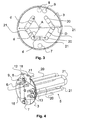
- FIG. 3 which shows the boiler base 3 with mounted tubular heater 5 in a view in the direction of boiler axis A
- the parallel to the boiler axis A extending portions 20 have a normal distance d to both the adjacent parallel portions 20 as well as the axis A of each one third of the inner diameter D of the boiler tank 1 on.
- the lead-through openings for the cold water connection 7 in the lowest area of the boiler base 3, for the hot water outlet 8 and for the temperature sensor 9 in the uppermost region of the boiler base 3 can be seen above the heating connections 6.
- the boiler bottom 3 is shown with mounted tubular heater 5 in a perspective view seen from the outside.
- the connections for the feedthroughs 7 for the cold water and for the hot water drain 8 and for the thermocouple 11 are pluggable and are held by a retaining plate 12, which is fastened to the boiler bottom 3 with the screws 16.
- the principle of the plug-in connections is shown with reference to the drawing 5.
- two circuit breakers 13 held by a holding plate 14 can be seen, which are electrically connected to the heating circuit, and interrupt it when the boiler overheats.
- the slots 18 in the upper region of the holding plate 12 are provided for a hanging, horizontal mounting of the boiler 1 in a coffee machine.
- FIG. 5 shows a schematic sectional view through a plug-in water connection sealingly in the bushings of the cold water supply 7 and in the hot water drainage passage 8 can be inserted and held by the holding plate 12.
- the tubular connection 10 has an annular groove for receiving a sealing element 15 and a collar-shaped extension 19 arranged above the annular groove.
- the sealing element 15 comes to rest within the bushing 7,8 and seals it.
- the collar-shaped extension 19 serves as a stop and rests on the surface of the boiler bottom 3.
- the holding plate 12 is inserted with corresponding, for example, keyhole-shaped recesses on the bushings 10 and bolted to the boiler bottom 3.
- connection for the thermocouple 11 is analogous to the water connections.
- the protruding into the interior of the boiler 1 extension 23 of the cold water supply 10 has to improve the Einströmeigenschaften the inflowing cold water, a conical extension of the inner diameter 22 against the end of the extension 23.
- a cold water or hot water pipe in the form of a pipe or hose is connected in a known manner.
- the boiler jacket and the side surfaces are covered with a thermally insulating layer to prevent heat emission to the outside as much as possible.
- a material for the boiler chrome steel is provided, the boiler jacket 2 is welded to the side walls 3,4.
- the required amount of hot water for the preparation of drinks can be provided with a lower electrical connection power than in conventional, comparable coffee machines.
- the tubular heater 5 extends almost over the entire volume of the boiler 1, whereby the heat is discharged evenly distributed over the entire volume of the water.
- the water has the required temperature. It has been found that in an immediately consecutive withdrawal of twenty and more portions of water to prepare a coffee beverage, the temperature of the withdrawn Water is constant and has the preset temperature.
Landscapes
- Engineering & Computer Science (AREA)
- Food Science & Technology (AREA)
- Apparatus For Making Beverages (AREA)
Description
- Die vorliegende Erfindung betrifft einen Boiler für Kaffeemaschinen zum Erwärmen von Wasser gemäss dem Oberbegriff des Anspruchs 1.
- Derartige Boiler werden in der Praxis bei Kaffee- und Espressomaschinen insbesondere bei gewerblich genutzten Maschinen verwendet. Der Boiler besteht aus einem geschlossenen, druckfesten meist zylindrischen Behälter mit einem Kaltwasserzulauf und einem Heisswasserablauf und einem Rohrheizkörper im Inneren des Behälters in Form einer stehend angeordneten Heizspirale. Das im Boiler befindliche Wasser wird auf die zum Brühen des Kaffees notwendige Temperatur aufgeheizt und ist mit einem Druck von der Grössenordnung von etwa 10 bar beaufschlagt. Bei der Zubereitung eines Getränks wird dem Boiler heisses Wasser entnommen und gleichzeitig fliesst die gleiche Menge kaltes Wasser nach. Dadurch sinkt die Wassertemperatur im Boiler. Die im Boiler angeordnete Heizung sorgt für die rasche Aufheizung des Wasser, so dass die Kaffeemaschine in kurzer Zeit wieder Betriebsbereit ist, das heisst, dass das nächste Getränk zubereitet werden kann. Bei gewerblich genutzten Maschinen wird erwartet, dass unmittelbar nach der Fertigstellung eines Getränks das nächste Getränk zubereitet werden kann. Die Zykluszeit ergibt sich somit aus der Brüh- und Kaffeebereitstellungs- und Kaffeeauswurfsphase der Kaffeemaschine. Die Aufheizzeit sollte diese Zykluszeit nicht verlängern. Um das zu erreichen werden in den Boilern Heizelemente mit möglichst hoher elektrischer Leistung eingesetzt. Der Nachteil der Heizelemente mit hoher Heizleistung ist, dass die Energiedichte am Heizkörper sehr gross ist und die Wärme gar nicht rasch genug vom Heizelement an die gesamte Wassermenge abgegeben werden kann. Die Windungen des Rohrheizkörpers liegen nahe nebeneinander, so dass sie sich gegenseitig beeinflussen, d.h. dass beim Erhitzen des Rohrheizkörpers die Wärme nicht nur an das Wasser sondern auch an die unmittelbar benachbarten Windungen abgegeben wird. Häufig führt das zu lokalen Überhitzungen mit Dampfbläschenbildung, was teilweise als leises Zischen sogar hörbar ist. An den Stellen, wo eine solche lokale Überhitzung auftritt, ist der Wärmeübergang zwischen Rohrheizkörper und Wasser wegen der Dampfbläschen schlechter als ohne Bläschenbildung, was insgesamt zu einer Reduktion des Wirkungsgrades der Heizanordnung führt.
- Es ist Aufgabe der vorliegenden Erfindung, einen Boiler für Kaffeemaschinen zum Erwärmen von Wasser bereitzustellen, der die genannten Nachteile traditioneller Vorrichtungen vermeidet.
- Die vorstehende Aufgabe wird von einem Boiler mit den Merkmalen des Anspruchs 1 gelöst. Weitere Merkmale und Vorteile der vorliegenden Erfindung werden an Hand der folgenden Beschreibung eines bevorzugten Ausführungsbeispiels insbesondere unter Bezugnahme der beigefügten Zeichnungen erläutert.
- Es zeigt die
- Figur 1
- eine perspektivische Darstellung des Boilergehäuses mit durchscheinendem Gehäusemantel;
- Figur 2
- eine perspektivische Darstellung des Boilerbodens mit der Heizanordnung von innen gesehen;
- Figur 3
- den Boilerboden mit montierter Heizanordnung in einer Ansicht in Richtung Boilerachse;
- Figur 4
- eine perspektivische Darstellung des Boilerbodens mit der Heizanordnung von aussen gesehen;
- Figur 5
- eine schematische Schnittzeichnung durch einen steckbaren Wasseranschluss.
- Das Prinzip des erfindungsgemässen Boilers liegt darin, dass mit einer entsprechend gestalteten Heizanordnung und einem isolierten Boilergehäuse mit geringerer elektrischer Energie als bei herkömmlichen, vergleichbaren Kaffeemaschinen in gleicher Zeit die benötigte Heisswassermenge bereit gestellt wird. Die durch vorzugsweise einen Rohrheizkörper gebildete Heizanordnung erstreckt sich nahezu über das gesamte Volumen des Boilers, wodurch die Wärme möglichst gleichzeitig und gleich verteilt über das gesamte Volumen an das Wasser abgegeben wird und keine lokalen Überhitzungen mit Dampfbildung entstehen können. Stellt man sich das Gesamtvolumen in kleine Einzelzellen aufgeteilt vor, so hat jeder Abschnitt des Rohrheizkörpers eine etwa gleich grosse Anzahl von Zellen, die den Heizkörper unmittelbar umgeben bzw. das gleiche Teilvolumen des Boilers, gleichzeitig aufzuheizen. Die zeitliche Verzögerung der Aufheizung des Wassers durch Konvektion für vom Heizkörper weiter entfernten Zellen, wie das bei üblichen Heizungsanordnungen der Fall ist, wird dadurch stark reduziert. Die Windungen des Rohrheizkörpers sind derart angeordnet, dass sie sich gegenseitig nicht mehr beeinflussen und beim Erhitzen des Rohrheizkörpers die Wärme nahezu nur an das Wasser abgegeben wird.
- In der
Figur 1 ist eine beispielsweise Ausführung des erfindungsgemässen Boilers 1 schematisch in einer perspektivischen Darstellung gezeigt. Das zylinderförmige druckfeste und aus rostfreiem Stahl gefertigte Boilergehäuse 1 mit einem Fassungsvermögen von etwa 1 l bis 2 l besteht aus einem Boilermantel 2 und aus den mit dem Mantel 2 verschweissten Seitenflächen, die senkrecht zur Zylinderachse angeordnet sind. Der Mantel 2 ist durchscheinend dargestellt, so dass im Inneren des Boilers 1 der Rohrheizkörper 5 zu erkennen ist. Die eine Seitenfläche des Boilergehäuses 1 bildet den Boilerdeckel 4 und die zweite Seitenfläche den Boilerboden 3 mit den Durchführungen für den Kaltwasseranschluss 7, für den Heisswasserabfluss 8, für einen Thermofühler 9 und den elektrischen Anschlüssen 6 für den Rohrheizkörper 5. Der Boiler 1 ist für einen horizontalen Betrieb ausgelegt, dass heisst, dass die Zylinderachse eines in eine Kaffeemaschine eingebauten Boilers 1 horizontal verläuft, und der zur Zylinderachse A senkrecht angeordnete Boilerboden 3 vertikal verläuft. Der Boilerboden 3 ist weiter so ausgerichtet, dass die Kaltwasserzuleitung 7 im unteren Bereich unterhalb der tiefstliegenden Schleife des Rohrheizkörpers 5 und die Heisswasserabflussleitung 8 im oberen Bereich des Boilerbodens 3 oberhalb der Anschlüsse 6 für den Rohrheizkörper 5 angeordnet sind. Unmittelbar neben dem Anschluss für die Heisswasserabflussleitung 8 ist eine Durchführung 9 für einen Thermofühler vorgesehen, der in das Innere des Boilergehäuses 1 ragt und zum Messen und Regeln der Wassertemperatur bestimmt ist. - Die
Figur 2 zeigt in einer perspektivischen Darstellung den Boilerboden 3 mit montiertem Rohrheizkörper 5. Der Rohrheizkörper 5 ist derart gestaltet, dass jeder Punkt innerhalb des Behältervolumens maximal einen Normalabstand vom Rohrheizkörper von 40% des Behälterdurchmessers D, vorzugsweise etwa 1/3 des Behälterdurchmessers D aufweist. Der Rohrheizkörper 5 besteht aus sechs in einem Abstand d von vorzugsweise etwa 1/3 des Behälterdurchmessers D parallel zur Zylinderachse A des Boilers 1 verlaufenden Abschnitten 20, die je eine Länge aufweisen, die grösser als 75% der Längsausdehnung des Boilergehäuses ist, und die einen Normalabstand d zu ihren benachbarten parallelen Abschnitten 20 von ebenfalls vorzugsweise etwa 1/3 des Behälterdurchmessers D aufweisen. Die Abstände d können aber zwischen 28% und 38% des Behälterdurchmessers D variieren, haben aber bevorzugt eine Länge von 1/3 des Behälterdurchmessers D. Der Rohrheizkörper 5 ist mit den im Boilergehäuse 1 zu oberst angeordneten und parallel zur Zylinderachse A verlaufenden Endabschnitten 17 am vertikal verlaufenden Boilerboden 3 befestigt. Über diese Befestigung werden die elektrischen Verbindungen des Heizkörpers 5 isoliert nach aussen zu den Anschlüssen 6 geführt. Herstellungsbedingt sind die Endabschnitte 17 des Rohrheizkörpers 5 nicht beheizt. Der Rohrheizkörper 5 ist so gestaltet, dass jeweils an den Enden der parallelen Abschnitte 20 ausser an den Endabschnitten 17 eine halbkreisförmige Krümmung 21 folgt die in den nächsten parallel verlaufenden Abschnitt 20 des Rohrheizkörpers 5 überführt. - Anhand der
Figur 3 , welche den Boilerboden 3 mit montiertem Rohrheizkörper 5 in einer Ansicht in Richtung Boilerachse A zeigt, ist die geometrische Anordnung der parallel zur Boilerachse A verlaufenden Abschnitte 20 und der halbgreisförmigen Krümmungen 21 zu erkennen. Die parallel zur Boilerachse A verlaufenden Abschnitte 20 weisen einen Normalabstand d sowohl zu den benachbarten parallelen Abschnitten 20 wie auch zur Achse A von jeweils einem Drittel des Innendurchmessers D des Boilerbehälters 1 auf. Weiter sind die Durchführungsöffnungen für den Kaltwasseranschluss 7 im untersten Bereich des Boilerbodens 3, für den Heisswasserabfluss 8 und für den Thermofühler 9 im obersten Bereich des Boilerbodens 3 oberhalb der Heizungsanschlüsse 6 zu erkennen. - In der
Figur 4 ist der Boilerboden 3 mit montiertem Rohrheizkörper 5 in einer perspektivischen Darstellung von aussen gesehen gezeigt. Die Anschlüsse für die Durchführungen 7 für das Kaltwasser und für den Heisswasserabfluss 8 und für den Thermofühler 11 sind steckbar und werden von einer Halteplatte 12, die am Boilerboden 3 mit den Schrauben 16 befestigt ist, gehalten. Das Prinzip der steckbaren Anschlüsse wird anhand der Zeichnung 5 gezeigt. Weiter sind zwei mit einer Halteplatte 14 gehaltene Schutzschalter 13 zu erkennen, die elektrisch mit dem Heizstromkreis verbunden sind, und diesen bei einer Überhitzung des Boilers unterbrechen. Die Schlitze 18 im oberen Bereich der Halteplatte 12 sind für eine hängende, horizontale Montage des Boilers 1 in einer Kaffeemaschine vorgesehen. - Die
Figur 5 zeigt eine schematische Schnittzeichnung durch einen steckbaren Wasseranschluss der dichtend in die Durchführungen der Kaltwasserzuführung 7 und in die Heisswasserabfluss-Durchführung 8 einsteckbar und von der Halteplatte 12 gehalten ist. Der rohrförmige Anschluss 10 weist eine Ringnut zur Aufnahme eines Dichtungselements 15 sowie eine oberhalb der Ringnut angeordnete kragenförmige Erweiterung 19 auf. Beim in den Boilerboden 3 eingesteckten Anschluss 10 kommt das Dichtungselement 15 innerhalb der Durchführung 7,8 zu liegen und dichtet diese ab. Die kragenförmige Erweiterung 19 dient als Anschlag und liegt auf der Oberfläche des Boilerbodens 3 auf. Die Halteplatte 12 wird mit entsprechenden, beispielsweise schlüssellochförmigen Ausnehmungen über die Durchführungen 10 gesteckt und mit dem Boilerboden 3 verschraubt. Dadurch sind die Anschlüsse gewindelos in den Durchführungen 7,8,9 fest und dichtend gehalten und erlauben eine einfache Montage und Demontage im Servicefall. Der Anschluss für den Thermofühler 11 erfolgt analog zu den Wasseranschlüssen. Der in das Innere des Boilers 1 ragende Fortsatz 23 des Kaltwasseranschlusses 10 weist zur Verbesserung der Einströmeigenschaften des zufliessenden Kaltwassers eine konische Erweiterung des Innendurchmessers 22 gegen das Ende des Fortsatzes 23 auf. Am äusseren Ende des Anschlusses 10 ist nach bekannter Art eine Kaltwasser- bzw. Heisswasserleitung in Form eines Rohres oder Schlauchs angeschlossen. - Der Boilermantel und die Seitenflächen sind mit einer thermisch isolierenden Schicht umhüllt, um eine Wärmeabgabe nach aussen möglichst zu unterbinden. Als Material für den Boiler ist Chromstahl vorgesehen, wobei der Boilermantel 2 mit den Seitenwänden 3,4 verschweisst ist. Als Material für den Boiler kommen aber auch Materialien als Chromstahl in Frage wie beispielsweise Kunststoff.
- Mit dem erfindungsgemässen Boiler 1 kann mit geringerer elektrischer Anschlussleistung als bei herkömmlichen, vergleichbaren Kaffeemaschinen die benötigte Heisswassermenge zur Zubereitung von Getränken bereit gestellt werden. Der Rohrheizkörper 5 erstreckt sich nahezu über das gesamte Volumen des Boilers 1, wodurch die Wärme gleichmässig verteilt über das gesamte Volumen an das Wasser abgegeben wird. Bei der Entnahme von Wasser für die Zubereitung eines Getränkes von etwa 200 ml strömt gleichzeitig die gleiche Menge kaltes Wasser nach und erwärmt sich bis zur Zubereitung des nächsten Getränkes soweit, dass auch bei der nächstfolgenden Heisswasserentnahme das Wasser die erforderliche Temperatur hat. Es hat sich gezeigt, dass bei einer unmittelbar aufeinander folgenden Entnahme von zwanzig und mehr Portionen an Wasser zur Zubereitung eines Kaffeegetränks die Temperatur des entnommenen Wassers konstant ist und die voreingestellten Temperatur aufweist. Das heisst, dass mit dem erfindungsgemässen Boiler bei den entnommenen Wassermengen keine Temperaturschwankungen durch das Ein- und Ausschalten des Heizungssystems auftreten und dass der bekannte Effekt der Temperatur Hysterese nicht erkennbar ist. Dadurch kann mit dem erfindungsgemässen Boiler sehr präzise die gewünschte Brühtemperatur voreingestellt werden.
Claims (10)
- Boiler für Kaffee- und Espressomaschinen zum Erwärmen von Wasser umfassend ein Boilergehäuse (1), einen Kaltwasserzufluss (7) und einen Heisswasserabfluss (8) sowie eine elektrische Heizeinrichtung (5), die in das Innere des Boilergehäuses (1) hineinragt, dadurch gekennzeichnet, dass das Boilergehäuse (1) eine zylindrische Form mit einem Boilermantel (2), einem Boilerdeckel (4) und einem Boilerboden (3) mit einer im Betrieb horizontal ausgerichteten Zylinderachse (A) aufweist, dass weiter die Kaltwasserzuleitung (7) sowie der Heisswasserabfluss (8) und die elektrische Heizeinrichtung (5) an einem vertikal verlaufenden Boilerboden (3) des Boilergehäuses (1) montiert sind, dass weiter die Heizeinrichtung (5) derart gestaltet ist, dass jeder Punkt innerhalb des Behältervolumens einen Normalabstand von der Heizeinrichtung (5) von weniger als 40% des Behälterdurchmessers (D) aufweist.
- Boiler nach Anspruch 1, dadurch gekennzeichnet, dass die Heizeinrichtung (5) von einem Rohrheizkörper (5) gebildet ist, welcher Rohrheizkörper (5) sechs parallel zur Zylinderachse (A) des Boilers (1) verlaufende Abschnitte (20) mit einen Normalabstand (d) sowohl zu den benachbarten parallelen Abschnitten (20) wie auch zur Achse (A) von jeweils etwa einem Drittel des Innendurchmessers (D) des Boilerbehälters (1) aufweist, und dass diese Abschnitte (20) je eine Länge aufweisen, die grösser als 70% der Längsausdehnung des Boilergehäuses (1) ist.
- Boiler nach Anspruch 1 oder 2, dadurch gekennzeichnet, dass der Rohrheizkörper (5) mit den im Boilergehäuse (1) zu oberst angeordneten und parallel zur Zylinderachse (A) verlaufenden Abschnitten (17) am Boilerboden (3) befestigt und über diese Befestigung die elektrische Verbindung des Rohrheizkörpers (5) nach aussen isoliert geführt ist.
- Boiler nach einem der vorhergehenden Ansprüche, dadurch gekennzeichnet, dass die Kaltwasserzuleitung (7) im unteren Bereich des vertikal verlaufenden Boilerbodens (3) und der Heisswasserabfluss (8) im oberen Bereich des Boilerbodens (3) angeordnet sind.
- Boiler nach einem der vorhergehenden Ansprüche, dadurch gekennzeichnet, dass im Bereich der Heisswasserabflusses (8) ein Temperaturfühler (9) am Boilerboden (3) angeordnet ist, der in das Innere des Boilergehäuses (1) ragt.
- Boiler nach einem der vorhergehenden Ansprüche, dadurch gekennzeichnet, dass die Anschlüsse für das Kaltwasser und für das Heisswasser steckbar sind.
- Boiler nach Anspruch 5, dadurch gekennzeichnet, dass der Temperaturfühler (11) steckbar ist.
- Boiler nach einem der vorhergehenden Ansprüche, dadurch gekennzeichnet, dass wenigstens ein thermischer Schutzschalter (13) am Boilergehäuse (1) angeordnet ist.
- Boiler nach einem der vorhergehenden Ansprüche, dadurch gekennzeichnet, dass das Boilergehäuses (1) mit einer thermisch isolierenden Schicht umhüllt ist.
- Boiler nach einem der vorhergehenden Ansprüche, dadurch gekennzeichnet, dass das Boilergehäuses (1) aus Kunststoff gefertigt ist.
Applications Claiming Priority (2)
| Application Number | Priority Date | Filing Date | Title |
|---|---|---|---|
| CH15572007 | 2007-10-08 | ||
| PCT/CH2008/000369 WO2009046550A2 (de) | 2007-10-08 | 2008-09-03 | Boiler für kaffeemaschinen zum erwärmen von wasser |
Publications (3)
| Publication Number | Publication Date |
|---|---|
| EP2197328A2 EP2197328A2 (de) | 2010-06-23 |
| EP2197328B1 true EP2197328B1 (de) | 2011-12-14 |
| EP2197328B8 EP2197328B8 (de) | 2012-03-14 |
Family
ID=40549638
Family Applications (1)
| Application Number | Title | Priority Date | Filing Date |
|---|---|---|---|
| EP08783469A Not-in-force EP2197328B8 (de) | 2007-10-08 | 2008-09-03 | Boiler für kaffeemaschinen zum erwärmen von wasser |
Country Status (6)
| Country | Link |
|---|---|
| US (1) | US8515268B2 (de) |
| EP (1) | EP2197328B8 (de) |
| CN (1) | CN101820803B (de) |
| AT (1) | ATE536784T1 (de) |
| ES (1) | ES2379417T3 (de) |
| WO (1) | WO2009046550A2 (de) |
Families Citing this family (24)
| Publication number | Priority date | Publication date | Assignee | Title |
|---|---|---|---|---|
| US8933372B2 (en) | 2006-06-29 | 2015-01-13 | Dynacurrent Technologies, Inc. | Engine pre-heater system |
| CA2639413A1 (en) * | 2008-09-11 | 2010-03-11 | Ray King | Closed loop heating system |
| GB2481217B (en) * | 2010-06-15 | 2017-06-07 | Otter Controls Ltd | Thick film heaters |
| CA2733302C (en) * | 2011-03-04 | 2012-08-28 | Ray King | Radiant heating system adapted for interchangeable assembly facilitating replacement of components |
| US9091457B2 (en) | 2011-03-04 | 2015-07-28 | Dynacurrent Technologies, Inc. | Electro-thermal heating system |
| ITMI20110725A1 (it) * | 2011-04-29 | 2012-10-30 | Roberto Celestino Santi | Dispositivo per la produzione di bevande calde. |
| USD677510S1 (en) | 2011-06-16 | 2013-03-12 | Calphalon Corporation | Coffee maker |
| WO2013029364A1 (zh) * | 2011-08-26 | 2013-03-07 | Chen Xiaoming | 优质热水的快速制备方法及装置 |
| US8731386B2 (en) * | 2011-09-30 | 2014-05-20 | Borgwarner Beru Systems Gmbh | Electric heating device for heating fluids |
| ITMO20120061A1 (it) * | 2012-03-12 | 2013-09-13 | T P A Impex Spa | Una caldaia per elettrodomestici e per impianti di riscaldamento di acqua per uso domestico ed industriale con produzione di vapore |
| US9822985B2 (en) * | 2012-11-01 | 2017-11-21 | Dynacurrent Technologies, Inc. | Radiant heating system |
| CN103388813B (zh) * | 2013-07-03 | 2016-06-01 | 广东新宝电器股份有限公司 | 一种蒸汽发生器 |
| US9809380B2 (en) | 2013-12-12 | 2017-11-07 | Savannah River Nuclear Solutions, Llc | Heat transfer unit and method for prefabricated vessel |
| US9957103B2 (en) | 2013-12-12 | 2018-05-01 | Savannah River Nuclear Solutions, Llc | Heat transfer unit and method for prefabricated vessel |
| CA2857765C (en) * | 2014-07-24 | 2023-09-26 | Ray King | Auxiliary heating system |
| US9651276B2 (en) * | 2014-08-29 | 2017-05-16 | Heateflex Corporation | Heater for solvents and flammable fluids |
| EP3393313B1 (de) * | 2015-12-23 | 2019-07-31 | Koninklijke Philips N.V. | Heizeranordnung zur verwendung in einem haushaltsgerät |
| CN105933997B (zh) * | 2016-05-24 | 2022-11-04 | 平湖科能电器技术有限公司 | 一种安装电热管的法兰封装结构 |
| CN107770887A (zh) * | 2016-08-22 | 2018-03-06 | 上海福沃机械有限公司 | 组合式电加热管 |
| RU174286U1 (ru) * | 2017-01-10 | 2017-10-10 | Юрий Яковлевич Никулин | Котел нагрева теплоносителя |
| US10859208B2 (en) | 2018-05-31 | 2020-12-08 | Savannah River Nuclear Solutions, Llc | Heat transfer unit for prefabricated vessel |
| US11906203B2 (en) * | 2019-09-27 | 2024-02-20 | Ademco Inc. | Water heater control system with powered anode rod |
| IT202400004327A1 (it) * | 2024-02-28 | 2025-08-28 | Steelform Srl | Serbatoio a pressione e relativo metodo di realizzazione |
| DE102024001069B3 (de) | 2024-03-21 | 2024-12-24 | Ludwig Steuer | Wasserkocher zum geräuscharmen Erhitzen von Flüssigkeiten |
Family Cites Families (5)
| Publication number | Priority date | Publication date | Assignee | Title |
|---|---|---|---|---|
| DE2552625A1 (de) * | 1975-11-24 | 1977-06-02 | Elpag Ag Chur | Vorrichtung zur verhinderung einer ueberhitzung von elektrisch beheizten geraeten |
| CN2561325Y (zh) * | 2002-07-26 | 2003-07-23 | 大统营实业股份有限公司 | 咖啡机加热装置 |
| US7461585B2 (en) * | 2004-11-24 | 2008-12-09 | Chris Nenov | Portable electrical expresso machine |
| CN200939053Y (zh) * | 2006-08-17 | 2007-08-29 | 李行 | 咖啡机加热装置 |
| WO2008098391A1 (de) | 2007-02-13 | 2008-08-21 | Egro Coffee Systems Ag | Boiler zum erwärmen von wasser und erzeugen von wasserdampf |
-
2008
- 2008-09-03 ES ES08783469T patent/ES2379417T3/es active Active
- 2008-09-03 WO PCT/CH2008/000369 patent/WO2009046550A2/de not_active Ceased
- 2008-09-03 US US12/682,021 patent/US8515268B2/en not_active Expired - Fee Related
- 2008-09-03 AT AT08783469T patent/ATE536784T1/de active
- 2008-09-03 CN CN2008801107013A patent/CN101820803B/zh not_active Expired - Fee Related
- 2008-09-03 EP EP08783469A patent/EP2197328B8/de not_active Not-in-force
Also Published As
| Publication number | Publication date |
|---|---|
| ES2379417T3 (es) | 2012-04-25 |
| US8515268B2 (en) | 2013-08-20 |
| EP2197328A2 (de) | 2010-06-23 |
| CN101820803A (zh) | 2010-09-01 |
| ATE536784T1 (de) | 2011-12-15 |
| EP2197328B8 (de) | 2012-03-14 |
| WO2009046550A3 (de) | 2009-08-13 |
| WO2009046550A2 (de) | 2009-04-16 |
| US20100239236A1 (en) | 2010-09-23 |
| CN101820803B (zh) | 2012-07-04 |
Similar Documents
| Publication | Publication Date | Title |
|---|---|---|
| EP2197328B8 (de) | Boiler für kaffeemaschinen zum erwärmen von wasser | |
| WO2009012904A2 (de) | Kompakte hochdruckfähige spiraldurchfluss-heizeinheit | |
| EP2458298A2 (de) | Elektrischer Wassererwärmer | |
| DE102009021656A1 (de) | Durchlauferhitzer und Verfahren zur Steuerung und Regelung eines solchen | |
| EP2350529B1 (de) | Haushaltsgerät mit einem befüllbaren dampfkessel und dampfkessel für ein haushaltsgerät | |
| DE19731351A1 (de) | Speicherwassererwärmer | |
| EP1936266A2 (de) | Vorrichtung zum Erhitzen einer Flüssigkeit und Kaffeemaschine | |
| EP2053951B1 (de) | Heisswasserbereiter, besonders für eine kaffeemaschine | |
| EP0630463B2 (de) | Elektrischer durchlauferhitzer | |
| EP3279570B1 (de) | Verdampfereinrichtung für wasser und dampfgarer mit einer solchen verdampfereinrichtung | |
| EP1964496B1 (de) | Durchlauferhitzer | |
| DE29810022U1 (de) | Schichtenspeicher | |
| EP2585769B1 (de) | Elektrischer durchlauferhitzer | |
| DE102006036802A1 (de) | Gerät zum Zubereiten von Heißgetränken und Heißgetränkheizeinrichtung zur Verwendung für die Erwärmung von Flüssigkeiten | |
| DE3834286A1 (de) | Heizvorrichtung fuer fluessigkeiten | |
| EP3640537B1 (de) | Verdampfereinrichtung und elektrogerät mit einer verdampfereinrichtung | |
| DE19829507B4 (de) | Innenbehälter für einen Heißwasserspeicher mit einem Flächenheizkörper | |
| DE102013008040A1 (de) | Vorrichtung zur Erwärmung von Wasser | |
| DE2741719C3 (de) | Elektrische Kaffee- oder Teemaschine | |
| DE10239494A1 (de) | Vorrichtung zum Aufheizen von Flüssigkeiten in einem wasserführenden Haushaltsgerät | |
| EP2829207B1 (de) | Durchlauferhitzer und Heißgetränkeautomat umfassend einen Durchlauferhitzer | |
| DE102023123893B4 (de) | Heizeinrichtung und wasserführendes Haushaltsgerät mit einer solchen Heizeinrichtung | |
| DE2639523C2 (de) | Heizeinrichtung für Kaffeemaschinen | |
| DE202007012762U1 (de) | Elektrischer Hängewasserhitzer | |
| AT410879B (de) | Elektro-warmwasserspeicher |
Legal Events
| Date | Code | Title | Description |
|---|---|---|---|
| PUAI | Public reference made under article 153(3) epc to a published international application that has entered the european phase |
Free format text: ORIGINAL CODE: 0009012 |
|
| 17P | Request for examination filed |
Effective date: 20100423 |
|
| AK | Designated contracting states |
Kind code of ref document: A2 Designated state(s): AT BE BG CH CY CZ DE DK EE ES FI FR GB GR HR HU IE IS IT LI LT LU LV MC MT NL NO PL PT RO SE SI SK TR |
|
| AX | Request for extension of the european patent |
Extension state: AL BA MK RS |
|
| GRAP | Despatch of communication of intention to grant a patent |
Free format text: ORIGINAL CODE: EPIDOSNIGR1 |
|
| DAX | Request for extension of the european patent (deleted) | ||
| GRAS | Grant fee paid |
Free format text: ORIGINAL CODE: EPIDOSNIGR3 |
|
| GRAA | (expected) grant |
Free format text: ORIGINAL CODE: 0009210 |
|
| AK | Designated contracting states |
Kind code of ref document: B1 Designated state(s): AT BE BG CH CY CZ DE DK EE ES FI FR GB GR HR HU IE IS IT LI LT LU LV MC MT NL NO PL PT RO SE SI SK TR |
|
| REG | Reference to a national code |
Ref country code: GB Ref legal event code: FG4D Free format text: NOT ENGLISH |
|
| REG | Reference to a national code |
Ref country code: CH Ref legal event code: EP |
|
| RAP2 | Party data changed (patent owner data changed or rights of a patent transferred) |
Owner name: EGRO SUISSE AG |
|
| REG | Reference to a national code |
Ref country code: IE Ref legal event code: FG4D |
|
| REG | Reference to a national code |
Ref country code: DE Ref legal event code: R096 Ref document number: 502008005861 Country of ref document: DE Effective date: 20120216 |
|
| REG | Reference to a national code |
Ref country code: DE Ref legal event code: R081 Ref document number: 502008005861 Country of ref document: DE Owner name: RANCILIO GROUP S.P.A., VILLASTANZA DI PARABIAG, IT Free format text: FORMER OWNER: EGRO COFFEE SYSTEMS AG, NIEDERROHRDORF, CH |
|
| REG | Reference to a national code |
Ref country code: NL Ref legal event code: T3 |
|
| REG | Reference to a national code |
Ref country code: CH Ref legal event code: NV Representative=s name: KEMIA SA |
|
| REG | Reference to a national code |
Ref country code: ES Ref legal event code: FG2A Ref document number: 2379417 Country of ref document: ES Kind code of ref document: T3 Effective date: 20120425 |
|
| PG25 | Lapsed in a contracting state [announced via postgrant information from national office to epo] |
Ref country code: NO Free format text: LAPSE BECAUSE OF FAILURE TO SUBMIT A TRANSLATION OF THE DESCRIPTION OR TO PAY THE FEE WITHIN THE PRESCRIBED TIME-LIMIT Effective date: 20120314 Ref country code: LT Free format text: LAPSE BECAUSE OF FAILURE TO SUBMIT A TRANSLATION OF THE DESCRIPTION OR TO PAY THE FEE WITHIN THE PRESCRIBED TIME-LIMIT Effective date: 20111214 |
|
| LTIE | Lt: invalidation of european patent or patent extension |
Effective date: 20111214 |
|
| PG25 | Lapsed in a contracting state [announced via postgrant information from national office to epo] |
Ref country code: SE Free format text: LAPSE BECAUSE OF FAILURE TO SUBMIT A TRANSLATION OF THE DESCRIPTION OR TO PAY THE FEE WITHIN THE PRESCRIBED TIME-LIMIT Effective date: 20111214 Ref country code: LV Free format text: LAPSE BECAUSE OF FAILURE TO SUBMIT A TRANSLATION OF THE DESCRIPTION OR TO PAY THE FEE WITHIN THE PRESCRIBED TIME-LIMIT Effective date: 20111214 Ref country code: GR Free format text: LAPSE BECAUSE OF FAILURE TO SUBMIT A TRANSLATION OF THE DESCRIPTION OR TO PAY THE FEE WITHIN THE PRESCRIBED TIME-LIMIT Effective date: 20120315 Ref country code: SI Free format text: LAPSE BECAUSE OF FAILURE TO SUBMIT A TRANSLATION OF THE DESCRIPTION OR TO PAY THE FEE WITHIN THE PRESCRIBED TIME-LIMIT Effective date: 20111214 Ref country code: HR Free format text: LAPSE BECAUSE OF FAILURE TO SUBMIT A TRANSLATION OF THE DESCRIPTION OR TO PAY THE FEE WITHIN THE PRESCRIBED TIME-LIMIT Effective date: 20111214 |
|
| PG25 | Lapsed in a contracting state [announced via postgrant information from national office to epo] |
Ref country code: CY Free format text: LAPSE BECAUSE OF FAILURE TO SUBMIT A TRANSLATION OF THE DESCRIPTION OR TO PAY THE FEE WITHIN THE PRESCRIBED TIME-LIMIT Effective date: 20111214 |
|
| REG | Reference to a national code |
Ref country code: IE Ref legal event code: FD4D |
|
| PG25 | Lapsed in a contracting state [announced via postgrant information from national office to epo] |
Ref country code: IE Free format text: LAPSE BECAUSE OF FAILURE TO SUBMIT A TRANSLATION OF THE DESCRIPTION OR TO PAY THE FEE WITHIN THE PRESCRIBED TIME-LIMIT Effective date: 20111214 Ref country code: EE Free format text: LAPSE BECAUSE OF FAILURE TO SUBMIT A TRANSLATION OF THE DESCRIPTION OR TO PAY THE FEE WITHIN THE PRESCRIBED TIME-LIMIT Effective date: 20111214 Ref country code: IS Free format text: LAPSE BECAUSE OF FAILURE TO SUBMIT A TRANSLATION OF THE DESCRIPTION OR TO PAY THE FEE WITHIN THE PRESCRIBED TIME-LIMIT Effective date: 20120414 Ref country code: SK Free format text: LAPSE BECAUSE OF FAILURE TO SUBMIT A TRANSLATION OF THE DESCRIPTION OR TO PAY THE FEE WITHIN THE PRESCRIBED TIME-LIMIT Effective date: 20111214 Ref country code: CZ Free format text: LAPSE BECAUSE OF FAILURE TO SUBMIT A TRANSLATION OF THE DESCRIPTION OR TO PAY THE FEE WITHIN THE PRESCRIBED TIME-LIMIT Effective date: 20111214 Ref country code: BG Free format text: LAPSE BECAUSE OF FAILURE TO SUBMIT A TRANSLATION OF THE DESCRIPTION OR TO PAY THE FEE WITHIN THE PRESCRIBED TIME-LIMIT Effective date: 20120314 |
|
| PG25 | Lapsed in a contracting state [announced via postgrant information from national office to epo] |
Ref country code: RO Free format text: LAPSE BECAUSE OF FAILURE TO SUBMIT A TRANSLATION OF THE DESCRIPTION OR TO PAY THE FEE WITHIN THE PRESCRIBED TIME-LIMIT Effective date: 20111214 Ref country code: PL Free format text: LAPSE BECAUSE OF FAILURE TO SUBMIT A TRANSLATION OF THE DESCRIPTION OR TO PAY THE FEE WITHIN THE PRESCRIBED TIME-LIMIT Effective date: 20111214 Ref country code: PT Free format text: LAPSE BECAUSE OF FAILURE TO SUBMIT A TRANSLATION OF THE DESCRIPTION OR TO PAY THE FEE WITHIN THE PRESCRIBED TIME-LIMIT Effective date: 20120416 |
|
| PLBE | No opposition filed within time limit |
Free format text: ORIGINAL CODE: 0009261 |
|
| STAA | Information on the status of an ep patent application or granted ep patent |
Free format text: STATUS: NO OPPOSITION FILED WITHIN TIME LIMIT |
|
| PG25 | Lapsed in a contracting state [announced via postgrant information from national office to epo] |
Ref country code: DK Free format text: LAPSE BECAUSE OF FAILURE TO SUBMIT A TRANSLATION OF THE DESCRIPTION OR TO PAY THE FEE WITHIN THE PRESCRIBED TIME-LIMIT Effective date: 20111214 |
|
| 26N | No opposition filed |
Effective date: 20120917 |
|
| REG | Reference to a national code |
Ref country code: DE Ref legal event code: R097 Ref document number: 502008005861 Country of ref document: DE Effective date: 20120917 |
|
| BERE | Be: lapsed |
Owner name: EGRO COFFEE SYSTEMS A.G. Effective date: 20120930 |
|
| PG25 | Lapsed in a contracting state [announced via postgrant information from national office to epo] |
Ref country code: MC Free format text: LAPSE BECAUSE OF NON-PAYMENT OF DUE FEES Effective date: 20120930 |
|
| PG25 | Lapsed in a contracting state [announced via postgrant information from national office to epo] |
Ref country code: FI Free format text: LAPSE BECAUSE OF FAILURE TO SUBMIT A TRANSLATION OF THE DESCRIPTION OR TO PAY THE FEE WITHIN THE PRESCRIBED TIME-LIMIT Effective date: 20111214 |
|
| PG25 | Lapsed in a contracting state [announced via postgrant information from national office to epo] |
Ref country code: BE Free format text: LAPSE BECAUSE OF NON-PAYMENT OF DUE FEES Effective date: 20120930 |
|
| PG25 | Lapsed in a contracting state [announced via postgrant information from national office to epo] |
Ref country code: MT Free format text: LAPSE BECAUSE OF FAILURE TO SUBMIT A TRANSLATION OF THE DESCRIPTION OR TO PAY THE FEE WITHIN THE PRESCRIBED TIME-LIMIT Effective date: 20111214 |
|
| PG25 | Lapsed in a contracting state [announced via postgrant information from national office to epo] |
Ref country code: TR Free format text: LAPSE BECAUSE OF FAILURE TO SUBMIT A TRANSLATION OF THE DESCRIPTION OR TO PAY THE FEE WITHIN THE PRESCRIBED TIME-LIMIT Effective date: 20111214 |
|
| PG25 | Lapsed in a contracting state [announced via postgrant information from national office to epo] |
Ref country code: LU Free format text: LAPSE BECAUSE OF NON-PAYMENT OF DUE FEES Effective date: 20120903 |
|
| PG25 | Lapsed in a contracting state [announced via postgrant information from national office to epo] |
Ref country code: HU Free format text: LAPSE BECAUSE OF FAILURE TO SUBMIT A TRANSLATION OF THE DESCRIPTION OR TO PAY THE FEE WITHIN THE PRESCRIBED TIME-LIMIT Effective date: 20080903 |
|
| REG | Reference to a national code |
Ref country code: AT Ref legal event code: MM01 Ref document number: 536784 Country of ref document: AT Kind code of ref document: T Effective date: 20130903 |
|
| PG25 | Lapsed in a contracting state [announced via postgrant information from national office to epo] |
Ref country code: AT Free format text: LAPSE BECAUSE OF NON-PAYMENT OF DUE FEES Effective date: 20130903 |
|
| REG | Reference to a national code |
Ref country code: FR Ref legal event code: PLFP Year of fee payment: 8 |
|
| REG | Reference to a national code |
Ref country code: GB Ref legal event code: 732E Free format text: REGISTERED BETWEEN 20160114 AND 20160120 |
|
| REG | Reference to a national code |
Ref country code: FR Ref legal event code: TP Owner name: RANCILIO GROUP SPA, IT Effective date: 20160315 |
|
| REG | Reference to a national code |
Ref country code: ES Ref legal event code: PC2A Owner name: RANCILIO GROUP, S.P.A. Effective date: 20160819 |
|
| REG | Reference to a national code |
Ref country code: FR Ref legal event code: PLFP Year of fee payment: 9 |
|
| REG | Reference to a national code |
Ref country code: NL Ref legal event code: PD Owner name: RANCILIO GROUP S.P.A.; IT Free format text: DETAILS ASSIGNMENT: CHANGE OF OWNER(S), ASSIGNMENT; FORMER OWNER NAME: EGRO SUISSE AG Effective date: 20161215 |
|
| REG | Reference to a national code |
Ref country code: DE Ref legal event code: R082 Ref document number: 502008005861 Country of ref document: DE Representative=s name: JACKISCH-KOHL UND KOHL, DE Ref country code: DE Ref legal event code: R081 Ref document number: 502008005861 Country of ref document: DE Owner name: RANCILIO GROUP S.P.A., VILLASTANZA DI PARABIAG, IT Free format text: FORMER OWNER: EGRO SUISSE AG, DOTTIKON, CH |
|
| REG | Reference to a national code |
Ref country code: FR Ref legal event code: PLFP Year of fee payment: 10 |
|
| REG | Reference to a national code |
Ref country code: FR Ref legal event code: PLFP Year of fee payment: 11 |
|
| REG | Reference to a national code |
Ref country code: CH Ref legal event code: NV Representative=s name: IPWAY SAGL, CH Ref country code: CH Ref legal event code: PUE Owner name: RANCILIO GROUP S.P.A., IT Free format text: FORMER OWNER: EGRO SUISSE AG, CH |
|
| REG | Reference to a national code |
Ref country code: CH Ref legal event code: PCAR Free format text: NEW ADDRESS: VIA FRANCESCO SOMAINI 9, 6900 LUGANO (CH) |
|
| PGFP | Annual fee paid to national office [announced via postgrant information from national office to epo] |
Ref country code: FR Payment date: 20200928 Year of fee payment: 13 Ref country code: NL Payment date: 20200908 Year of fee payment: 13 Ref country code: GB Payment date: 20200929 Year of fee payment: 13 |
|
| PGFP | Annual fee paid to national office [announced via postgrant information from national office to epo] |
Ref country code: IT Payment date: 20200828 Year of fee payment: 13 |
|
| PGFP | Annual fee paid to national office [announced via postgrant information from national office to epo] |
Ref country code: CH Payment date: 20201209 Year of fee payment: 13 Ref country code: ES Payment date: 20201001 Year of fee payment: 13 Ref country code: DE Payment date: 20201126 Year of fee payment: 13 |
|
| REG | Reference to a national code |
Ref country code: DE Ref legal event code: R119 Ref document number: 502008005861 Country of ref document: DE |
|
| REG | Reference to a national code |
Ref country code: CH Ref legal event code: PL |
|
| REG | Reference to a national code |
Ref country code: NL Ref legal event code: MM Effective date: 20211001 |
|
| GBPC | Gb: european patent ceased through non-payment of renewal fee |
Effective date: 20210903 |
|
| PG25 | Lapsed in a contracting state [announced via postgrant information from national office to epo] |
Ref country code: NL Free format text: LAPSE BECAUSE OF NON-PAYMENT OF DUE FEES Effective date: 20211001 |
|
| PG25 | Lapsed in a contracting state [announced via postgrant information from national office to epo] |
Ref country code: GB Free format text: LAPSE BECAUSE OF NON-PAYMENT OF DUE FEES Effective date: 20210903 Ref country code: FR Free format text: LAPSE BECAUSE OF NON-PAYMENT OF DUE FEES Effective date: 20210930 Ref country code: DE Free format text: LAPSE BECAUSE OF NON-PAYMENT OF DUE FEES Effective date: 20220401 |
|
| PG25 | Lapsed in a contracting state [announced via postgrant information from national office to epo] |
Ref country code: LI Free format text: LAPSE BECAUSE OF NON-PAYMENT OF DUE FEES Effective date: 20210930 Ref country code: CH Free format text: LAPSE BECAUSE OF NON-PAYMENT OF DUE FEES Effective date: 20210930 |
|
| PG25 | Lapsed in a contracting state [announced via postgrant information from national office to epo] |
Ref country code: IT Free format text: LAPSE BECAUSE OF NON-PAYMENT OF DUE FEES Effective date: 20210903 |
|
| REG | Reference to a national code |
Ref country code: ES Ref legal event code: FD2A Effective date: 20221102 |
|
| PG25 | Lapsed in a contracting state [announced via postgrant information from national office to epo] |
Ref country code: ES Free format text: LAPSE BECAUSE OF NON-PAYMENT OF DUE FEES Effective date: 20210904 |