EP2196881A1 - Control device for operating an automated machine - Google Patents
Control device for operating an automated machine Download PDFInfo
- Publication number
- EP2196881A1 EP2196881A1 EP08021094A EP08021094A EP2196881A1 EP 2196881 A1 EP2196881 A1 EP 2196881A1 EP 08021094 A EP08021094 A EP 08021094A EP 08021094 A EP08021094 A EP 08021094A EP 2196881 A1 EP2196881 A1 EP 2196881A1
- Authority
- EP
- European Patent Office
- Prior art keywords
- operating device
- screen
- machine
- touch
- locations
- Prior art date
- Legal status (The legal status is an assumption and is not a legal conclusion. Google has not performed a legal analysis and makes no representation as to the accuracy of the status listed.)
- Withdrawn
Links
- 238000005516 engineering process Methods 0.000 claims description 24
- 238000009434 installation Methods 0.000 claims description 6
- 238000004519 manufacturing process Methods 0.000 claims description 3
- 239000007788 liquid Substances 0.000 description 4
- 239000002245 particle Substances 0.000 description 4
- 238000003754 machining Methods 0.000 description 2
- 238000003825 pressing Methods 0.000 description 2
- 230000001133 acceleration Effects 0.000 description 1
- 230000001419 dependent effect Effects 0.000 description 1
- 238000001514 detection method Methods 0.000 description 1
- 230000007613 environmental effect Effects 0.000 description 1
- 230000007257 malfunction Effects 0.000 description 1
- 230000000149 penetrating effect Effects 0.000 description 1
- 238000004088 simulation Methods 0.000 description 1
- 230000003068 static effect Effects 0.000 description 1
Images
Classifications
-
- G—PHYSICS
- G05—CONTROLLING; REGULATING
- G05B—CONTROL OR REGULATING SYSTEMS IN GENERAL; FUNCTIONAL ELEMENTS OF SUCH SYSTEMS; MONITORING OR TESTING ARRANGEMENTS FOR SUCH SYSTEMS OR ELEMENTS
- G05B19/00—Programme-control systems
- G05B19/02—Programme-control systems electric
- G05B19/18—Numerical control [NC], i.e. automatically operating machines, in particular machine tools, e.g. in a manufacturing environment, so as to execute positioning, movement or co-ordinated operations by means of programme data in numerical form
- G05B19/409—Numerical control [NC], i.e. automatically operating machines, in particular machine tools, e.g. in a manufacturing environment, so as to execute positioning, movement or co-ordinated operations by means of programme data in numerical form characterised by using manual data input [MDI] or by using control panel, e.g. controlling functions with the panel; characterised by control panel details or by setting parameters
-
- G—PHYSICS
- G05—CONTROLLING; REGULATING
- G05B—CONTROL OR REGULATING SYSTEMS IN GENERAL; FUNCTIONAL ELEMENTS OF SUCH SYSTEMS; MONITORING OR TESTING ARRANGEMENTS FOR SUCH SYSTEMS OR ELEMENTS
- G05B2219/00—Program-control systems
- G05B2219/30—Nc systems
- G05B2219/35—Nc in input of data, input till input file format
- G05B2219/35072—Scale, zoom a designed figure
-
- G—PHYSICS
- G05—CONTROLLING; REGULATING
- G05B—CONTROL OR REGULATING SYSTEMS IN GENERAL; FUNCTIONAL ELEMENTS OF SUCH SYSTEMS; MONITORING OR TESTING ARRANGEMENTS FOR SUCH SYSTEMS OR ELEMENTS
- G05B2219/00—Program-control systems
- G05B2219/30—Nc systems
- G05B2219/36—Nc in input of data, input key till input tape
- G05B2219/36168—Touchscreen
Definitions
- the invention relates to an operating device for operating a machine from automation technology.
- buttons and the mouse are vulnerable to penetrating dirt particles and liquids. Furthermore, dirt particles and liquids can penetrate via the buttons in the operating device and damage the sensitive electronics inside the operating device, which can lead to failure of the operating device or malfunction. Particularly in the environment of automation technology machines, dirt particles and liquids often occur, e.g. caused by a machining process of a workpiece on.
- an operating device for operating a machine from automation technology wherein the operating device is designed for stationary installation in a control panel of the machine and / or in a cabinet of the machine, wherein the operating device has a touch-sensitive screen, wherein of the screen Touch locations of at least two at different locations of the screen simultaneously occurring touches of the screen are detected, wherein the operating device is designed such that at a detected simultaneous change of touch locations, according to the local characteristics of the touch locations, a visualized by the screen of the operating device object on the Screen is displayed changed.
- the object is displayed enlarged, if the local courses of the touch locations in opposite and diverging directions, since then in a simple manner, the object can be displayed enlarged or reduced on the screen.
- the object is displayed shifted, if the local courses of the touch location in the same directions, since then in a simple manner, the object can be moved on the screen.
- the touch locations are above the object shown on the screen, as this allows a particularly simple operation.
- the touch locations may also be adjacent to the object displayed on the screen, so that e.g. fingers used for operation do not necessarily have to touch the screen over the object to operate.
- the machine is designed from automation technology as a machine tool, production machine and / or robot.
- FIG. 1 is shown in the form of a schematic representation of an operating device 1 according to the invention.
- the operating device 1 has a touch-sensitive screen 2, wherein from the screen 2, the touch locations 4a and 4b of at least two simultaneously occurring at different points of the screen touches of the screen 2 are detected.
- the technology that allows simultaneous detection of two or more touches on a screen is also referred to as multi-point touch technology.
- the operating device is designed such that at a detected simultaneous change of touch locations 4a and 4b, according to the local characteristics of the touch location, a visualized by the screen 2 of the operating device 1 object 3, which is formed in the context of the embodiment as a workpiece on the screen 2 is displayed changed.
- the operator wishes to enlarge the object 3, he touches the object 3 on the screen at the first point of contact 4a with a finger of the left hand and with the finger of the right hand at the point of contact 4b.
- FIG. 2 shows the object 3 shown enlarged accordingly. Accordingly, the object is reduced in size when the local courses of the touch locations 4a and 4b are in opposite and mutually extending directions.
- the operating device 1 is designed for stationary installation in a control panel and / or a cabinet of a machine from automation technology.
- the operating device can for this purpose e.g. but also on the back and / or on the lateral sides of the operating device arranged clamping means with which the operating device in the control panel and / or in the cabinet, in particular in the cabinet door, can be attached and thus can be installed stationary.
- the operating device can, however, for this purpose, for example. have laterally only grooves or holes in the fasteners, such. Screws, intervene.
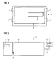
- FIG. 5 is in the form of a schematic representation of a machine from automation technology, which is designed as a machine tool 11 in the context of the embodiment illustrated.
- a control panel 10 is connected via an arm 9 to a housing 14 which essentially contains the mechanical parts of the machine tool, the encoder of the machine tool and the motors of the machine tool.
- the operating device 1 is installed stationary in the control panel 10 for operating the machine.
- the machine tool 11 has a cabinet 12, which is formed in the context of the embodiment as a control cabinet and contains the components required for the control and regulation of the machine tool.
- the cabinet 12 is electrically connected via electrical connections 13 to the motors and encoders of the machine tool.
- the control device according to the invention 1 installed in the cabinet 12, wherein the operating device 1 is installed in the door of the cabinet 12, so that from the outside on the cabinet and an operation of the machine tool is possible.
- the operating device according to the invention can be installed in machines of automation technology stationary in the control panel of the machine and / or in a cabinet, in particular a control cabinet of the machine.
- an installation in a cabinet of a machine from automation technology also means an installation in a door of the cabinet of a machine from automation technology.
- an operation of a machine from automation technology also includes inter alia also a programming of the machine and the performance of simulations for machining operations.
- a hand can be placed on the screen and then to change the object e.g. can be rotated so that there are more than two touch locations detected and physical locations of the touch locations.
Landscapes
- Engineering & Computer Science (AREA)
- Human Computer Interaction (AREA)
- Manufacturing & Machinery (AREA)
- Physics & Mathematics (AREA)
- General Physics & Mathematics (AREA)
- Automation & Control Theory (AREA)
- Numerical Control (AREA)
Abstract
Description
Die Erfindung betrifft eine Bedieneinrichtung zur Bedienung einer Maschine aus der Automatisierungstechnik.The invention relates to an operating device for operating a machine from automation technology.
Bei handelsüblichen Bedieneinrichtungen zur Bedienung von Maschinen aus der Automatisierungstechnik, wie z.B. Werkzeugmaschinen, Produktionsmaschinen und/oder Robotern, erfolgt das Verändern von auf dem Bildschirm der Bedieneinrichtung dargestellten Objekten, wie z.B. einem Werkstück, durch das Drücken von Tasten und/oder Bewegungen einer Maus. Das dargestellte Objekt kann dabei z.B. mittels Tasten- und/oder Mausbewegungen vergrößert und/oder verschoben werden.In commercially available operating devices for operating machines from automation technology, such. Machine tools, production machines and / or robots, the changing of displayed on the screen of the operating device objects, such as. a workpiece, by pressing keys and / or movements of a mouse. The illustrated object may e.g. be enlarged and / or moved by means of key and / or mouse movements.
Eine solche handelsübliche Bedienung ist aber für den Anwender recht komplex, weil die Bedienhandlungen, die er ausführen muss, um das am Bildschirm dargestellte Objekt zu verändern, komplexe Handbewegungen und das Drücken von Tasten erfordert.However, such commercial operation is quite complex for the user, because the operations he has to perform to change the on-screen object requires complex hand movements and the pressing of keys.
Weiterhin sind die Tasten und die Maus anfällig gegenüber eindringende Schmutzpartikel und Flüssigkeiten. Weiterhin können über die Tasten in die Bedieneinrichtung Schmutzpartikel und Flüssigkeiten eindringen und die empfindliche Elektronik im Inneren der Bedieneinrichtung beschädigen, was zu einem Ausfall der Bedieneinrichtung oder zu Fehlfunktionen führen kann. Insbesondere im Umfeld von Maschinen aus der Automatisierungstechnik treten häufig Schmutzpartikel und Flüssigkeiten, welche z.B. durch einen Bearbeitungsvorgang eines Werkstücks entstehen, auf.Furthermore, the buttons and the mouse are vulnerable to penetrating dirt particles and liquids. Furthermore, dirt particles and liquids can penetrate via the buttons in the operating device and damage the sensitive electronics inside the operating device, which can lead to failure of the operating device or malfunction. Particularly in the environment of automation technology machines, dirt particles and liquids often occur, e.g. caused by a machining process of a workpiece on.
Aus der
Aus der
Weiterhin sind auch noch mit Beschleunigungssensoren ausgestattete Handschuhe bekannt, mit denen insbesondere virtuelle 3D-Gegenstände bewegt werden können. Der Einsatz eines solchen speziellen Handschuhs ist aber zum einen sehr kostenintensiv und zum anderen beim Einsatz in der Automatisierungstechnik wegen der harten Umgebungsbedingungen (z.B. Verschmutzung) nicht praktikabel.Furthermore, even equipped with acceleration sensors gloves are known, with which in particular virtual 3D objects can be moved. However, the use of such a special glove is on the one hand very expensive and on the other hand, when used in automation technology because of the harsh environmental conditions (such as pollution) not practical.
Es ist Aufgabe der Erfindung, eine Bedieneinrichtung zur Bedienung einer Maschine aus der Automatisierungstechnik zu schaffen, bei der ein an einem Bildschirm der Bedieneinrichtung visualisiertes Objekt mittels einfacher Bedienhandlungen am Bildschirm verändert werden kann und die unempfindlicher gegenüber die Bedieneinrichtung umgebende Schmutzpartikel und Flüssigkeiten ist.It is an object of the invention to provide an operating device for operating a machine from automation technology, in which a visualized on a screen of the operating device object can be changed by simple operator actions on the screen and the less sensitive to the control device surrounding dirt particles and liquids.
Diese Aufgabe wird gelöst durch eine Bedieneinrichtung zur Bedienung einer Maschine aus der Automatisierungstechnik, wobei die Bedieneinrichtung zum stationären Einbau in einen Bedienpult der Maschine und/oder in einen Schrank der Maschine ausgebildet ist, wobei die Bedieneinrichtung einen berührungsempfindlichen Bildschirm aufweist, wobei von dem Bildschirm die Berührungsorte von mindestens zwei an unterschiedlichen Stellen des Bildschirms gleichzeitig stattfindenden Berührungen des Bildschirms detektierbar sind, wobei die Bedieneinrichtung derart ausgebildet ist, dass bei einer detektierten gleichzeitigen Änderung der Berührungsorte, entsprechend den örtlichen Verläufen der Berührungsorte, ein von dem Bildschirm der Bedieneinrichtung visualisiertes Objekt auf dem Bildschirm verändert dargestellt wird.This object is achieved by an operating device for operating a machine from automation technology, wherein the operating device is designed for stationary installation in a control panel of the machine and / or in a cabinet of the machine, wherein the operating device has a touch-sensitive screen, wherein of the screen Touch locations of at least two at different locations of the screen simultaneously occurring touches of the screen are detected, wherein the operating device is designed such that at a detected simultaneous change of touch locations, according to the local characteristics of the touch locations, a visualized by the screen of the operating device object on the Screen is displayed changed.
Vorteilhafte Ausbildungen der Erfindung ergeben sich aus den abhängigen Ansprüchen.Advantageous embodiments of the invention will become apparent from the dependent claims.
Es erweist sich als vorteilhaft, wenn das Objekt vergrößert dargestellt wird, wenn die örtlichen Verläufe der Berührungsorte in entgegengesetzt und auseinander verlaufenden Richtungen verlaufen, da dann auf einfache Art und Weise das Objekt am Bildschirm vergrößert oder verkleinert dargestellt werden kann.It proves to be advantageous if the object is displayed enlarged, if the local courses of the touch locations in opposite and diverging directions, since then in a simple manner, the object can be displayed enlarged or reduced on the screen.
Ferner erweist es sich als vorteilhaft, wenn das Objekt verschoben dargestellt wird, wenn die örtlichen Verläufe der Berührungsorte in gleiche Richtungen verlaufen, da dann auf einfache Art und Weise das Objekt am Bildschirm verschoben werden kann.Furthermore, it proves to be advantageous if the object is displayed shifted, if the local courses of the touch location in the same directions, since then in a simple manner, the object can be moved on the screen.
Ferner erweist es sich als vorteilhaft, wenn das Objekt gedreht dargestellt wird, wenn die örtlichen Verläufe der Berührungsorte einen kreisbogenförmigen Verlauf aufweisen, da dann auf einfache Art und Weise das Objekt gedreht werden kann.Furthermore, it proves to be advantageous if the object is shown rotated, if the local courses of the contact points have a circular arc, since then in a simple manner, the object can be rotated.
Ferner erweist es sich als vorteilhaft, wenn die Berührungsorte über dem am Bildschirm dargestellten Objekt liegen, da hierdurch eine besonders einfache Bedienung ermöglicht wird. Selbstverständlich können die Berührungsorte aber auch neben dem am Bildschirm dargestellten Objekt liegen, so dass z.B. zur Bedienung verwendete Finger nicht unbedingt über dem Objekt den Bildschirm zur Bedienung berühren müssen.Furthermore, it proves to be advantageous if the touch locations are above the object shown on the screen, as this allows a particularly simple operation. Of course, however, the touch locations may also be adjacent to the object displayed on the screen, so that e.g. fingers used for operation do not necessarily have to touch the screen over the object to operate.
Ferner erweist es sich als vorteilhaft, wenn die Maschine aus der Automatisierungstechnik als Werkzeugmaschine, Produktionsmaschine und/oder als Roboter ausgebildet ist.Furthermore, it proves to be advantageous if the machine is designed from automation technology as a machine tool, production machine and / or robot.
Ferner erweist es sich als vorteilhaft ein Bedienpult einer Maschine aus der Automatisierungstechnik mit der erfindungsgemäßen Bedieneinrichtung auszubilden.Furthermore, it proves to be advantageous to form a control panel of a machine from automation technology with the operating device according to the invention.
Weiterhin erweist es sich als vorteilhaft, einen Schrank einer Maschine aus der Automatisierungstechnik mit der erfindungsgemäßen Bedieneinrichtung auszubilden.Furthermore, it proves to be advantageous to form a cabinet of a machine from automation technology with the operating device according to the invention.
Vorteilhafte Ausbildungen der Erfindung sind in der Zeichnung dargestellt. Dabei zeigen:
- FIG 1
- eine erfindungsgemäße Bedieneinrichtung mit einem Bildschirm, auf dem ein Objekt dargestellt ist,
- FIG 2
- eine erfindungsgemäße Bedieneinrichtung, bei der das Objekt vergrößert dargestellt ist,
- FIG 3
- eine erfindungsgemäße Bedieneinrichtung, bei der das Objekt gedreht dargestellt ist,
- FIG 4
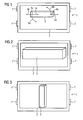
- die erfindungsgemäße Bedieneinrichtung, bei der das Objekt verschoben dargestellt ist, und
- FIG 5
- eine Maschine aus der Automatisierungstechnik mit einem Bedienpult und einem Schrank.
- FIG. 1
- an operating device according to the invention with a screen on which an object is shown,
- FIG. 2
- an operating device according to the invention, in which the object is shown enlarged,
- FIG. 3
- an operating device according to the invention, in which the object is shown rotated,
- FIG. 4
- the operating device according to the invention, in which the object is shown displaced, and
- FIG. 5
- a machine from automation technology with a control panel and a cabinet.
In
Die Bedieneinrichtung ist erfindungsgemäß derart ausgebildet, dass bei einer detektierten gleichzeitigen Änderung der Berührungsorte 4a und 4b, entsprechend den örtlichen Verläufen der Berührungsorte, ein von dem Bildschirm 2 der Bedieneinrichtung 1 visualisiertes Objekt 3, das im Rahmen des Ausführungsbeispiels als ein Werkstück ausgebildet ist, auf dem Bildschirm 2 verändert dargestellt wird.The operating device according to the invention is designed such that at a detected simultaneous change of
Möchte der Bediener z.B. das Objekt 3 vergrößert dargestellt haben, so berührt er z.B. mit einem Finger der linken Hand das Objekt 3 auf dem Bildschirm am ersten Berührungsort 4a und mit einem Finger der rechten Hand am Berührungsort 4b.For example, if the operator wishes to enlarge the
Anschließend bewegt er gleichzeitig seinen Finger der linken Hand in Richtung des Pfeils 5a und seinen Finger der rechten Hand in Richtung des Pfeils 5b, wobei die beiden Finger während der Bewegung den Bildschirm berühren. Solchermaßen entsteht ein örtlicher Verlauf des ersten Berührungsorts 4a in Richtung des Pfeils 5a und ein örtlicher Verlauf des zweiten Berührungsorts 4b in Richtung des Pfeils 5b. Die gleichzeitige Änderung der Berührungsorte wird, wie schon beschrieben, von der Bedieneinrichtung 1 detektiert, ausgewertet und entsprechend den örtlichen Verläufen der Berührungsorte 4a und 4b wird das auf dem Bildschirm der Bedieneinrichtung visualisierte Objekt verändert dargestellt.He then simultaneously moves his left-hand finger in the direction of the
Wenn, wie oben beschrieben, die örtlichen Verläufe der Berührungsorte 4a und 4b in entgegengesetze und in auseinander laufenden Richtungen verlaufen, wird der Objekt 3 vergrößert dargestellt.
Wenn die örtlichen Verläufe der Berührungsorte gleichzeitig in gleiche Richtungen verlaufen, d.h. z.B. der erste Berührungsort 4a in Richtung des Pfeils 14 und der zweite Bedienungsort 4b gleichzeitig in Richtung des Pfeils 5b bewegt wird, wird das Objekt 3 verschoben auf dem Bildschirm 2 dargestellt. In
Wenn der linke Finger und damit der erste Berührungsort 4a in Richtung des Pfeils 6a bewegt wird, und somit der erste Berührungsort 4a einen kreisbogenförmigen Verlauf aufweist und gleichzeitig der rechte Finger in Richtung des Pfeils 6b bewegt wird, d.h. der zweite Berührungsort 4b in Richtung des Pfeils 6b bewegt wird und somit der örtliche Verlauf des Berührungsorts 4b einen kreisbogenförmigen Verlauf aufweist, dann wird das Objekt gedreht dargestellt, was in
Die Bedieneinrichtung 1 ist dabei zum stationären Einbau in ein Bedienpult und/oder einen Schrank einer Maschine aus der Automatisierungstechnik ausgebildet. Hierzu weist im Rahmen des Ausführungsbeispiels die Bedieneinrichtung 1 Befestigungsmittel 7 auf, die z.B. in Form von Halterungen vorliegen können. Die Bedieneinrichtung kann hierzu z.B. aber auch auf der Rückseite und/oder auf den seitlichen Seiten der Bedieneinrichtung angeordnete Spannmittel aufweisen, mit der die Bedieneinrichtung in den Bedienpult und/oder im Schrank, insbesondere in der Schränktür, befestigt werden kann und solchermaßen stationär eingebaut werden kann. Die Bedieneinrichtung kann aber hierzu z.B. seitlich auch nur Nuten oder Löcher aufweisen in die Befestigungsmittel, wie z.B. Schrauben, eingreifen. Es sind hier eine Vielzahl von Befestigungsmöglichkeiten zum statischen Einbau der Bedieneinrichtung in einen Bedienpult und/oder einen Schrank einer Maschine aus der Automatisierungstechnik möglich.The
In
Weiterhin weist die Werkzeugmaschine 11 einen Schrank 12 auf, der im Rahmen des Ausführungsbeispiels als Schaltschrank ausgebildet ist und die zur Steuerung und Regelung benötigten Komponenten der Werkzeugmaschine enthält. Der Schrank 12 ist über elektrische Verbindungen 13 mit den Motoren und Gebern der Werkzeugmaschine, elektrisch verbunden. Im Rahmen des Ausführungsbeispiels ist dabei die erfindungsgemäße Bedieneinrichtung 1 in den Schrank 12 eingebaut, wobei die Bedieneinrichtung 1 in die Tür des Schranks 12 eingebaut ist, so dass von außen über den Schrank auch eine Bedienung der Werkzeugmaschine möglich ist. Es sei an dieser Stelle angemerkt, dass allgemein gesprochen die erfindungsgemäße Bedieneinrichtung bei Maschinen aus der Automatisierungstechnik stationär im Bedienpult der Maschine und/oder in einem Schrank, insbesondere einem Schaltschrank der Maschine, eingebaut sein kann.Furthermore, the
Es sei an dieser Stelle ebenfalls angemerkt, dass im Rahmen der Erfindung unter einem Einbau in einen Schrank einer Maschine aus der Automatisierungstechnik unter anderem insbesondere auch ein Einbau in eine Tür des Schranks einer Maschine aus der Automatisierungstechnik verstanden wird.It should also be noted at this point that, in the context of the invention, an installation in a cabinet of a machine from automation technology, inter alia, also means an installation in a door of the cabinet of a machine from automation technology.
Es sei weiterhin an dieser Stelle angemerkt, dass im Rahmen der Erfindung unter einer Bedienung einer Maschine aus der Automatisierungstechnik unter anderem insbesondere auch eine Programmierung der Maschine und die Durchführung von Simulationen zu Bearbeitungsvorgängen verstanden werden.It should also be noted at this point that, in the context of the invention, an operation of a machine from automation technology also includes inter alia also a programming of the machine and the performance of simulations for machining operations.
Weiterhin sei an dieser Stelle angemerkt, dass anstelle der beiden Finger, z.B. zum Drehen des Objekts, z.B. auch eine Hand auf den Bildschirm gelegt werden kann und dann zur Veränderung des Objekts z.B. gedreht werden kann, so dass mehr wie zwei Berührungsorte, welche detektiert werden und örtliche Verläufe der Berührungsorte, vorhanden sind.Furthermore, it should be noted at this point that instead of the two fingers, e.g. for rotating the object, e.g. also a hand can be placed on the screen and then to change the object e.g. can be rotated so that there are more than two touch locations detected and physical locations of the touch locations.
Claims (8)
Priority Applications (1)
| Application Number | Priority Date | Filing Date | Title |
|---|---|---|---|
| EP08021094A EP2196881A1 (en) | 2008-12-04 | 2008-12-04 | Control device for operating an automated machine |
Applications Claiming Priority (1)
| Application Number | Priority Date | Filing Date | Title |
|---|---|---|---|
| EP08021094A EP2196881A1 (en) | 2008-12-04 | 2008-12-04 | Control device for operating an automated machine |
Publications (1)
| Publication Number | Publication Date |
|---|---|
| EP2196881A1 true EP2196881A1 (en) | 2010-06-16 |
Family
ID=40380511
Family Applications (1)
| Application Number | Title | Priority Date | Filing Date |
|---|---|---|---|
| EP08021094A Withdrawn EP2196881A1 (en) | 2008-12-04 | 2008-12-04 | Control device for operating an automated machine |
Country Status (1)
| Country | Link |
|---|---|
| EP (1) | EP2196881A1 (en) |
Cited By (5)
| Publication number | Priority date | Publication date | Assignee | Title |
|---|---|---|---|---|
| EP2407869A1 (en) * | 2010-07-12 | 2012-01-18 | Lg Electronics Inc. | Mobile terminal and controlling method thereof |
| EP2444866A1 (en) | 2010-10-19 | 2012-04-25 | Siemens Aktiengesellschaft | Control device for operating an automated machine |
| WO2012066020A3 (en) * | 2010-11-17 | 2013-06-20 | Netstal-Maschinen Ag | Control device having multi-touch functionality |
| EP2709803B1 (en) | 2011-05-16 | 2016-12-21 | Kaba Ag | Method for influencing movements of a machine or facility in a manually controlled manner and corresponding machine control system |
| EP4023398A4 (en) * | 2019-08-26 | 2023-09-13 | Kawasaki Jukogyo Kabushiki Kaisha | Information processing device, configuration device, image recognition system, robot system, configuration method, learning device, and learned model generation method |
Citations (8)
| Publication number | Priority date | Publication date | Assignee | Title |
|---|---|---|---|---|
| US6088628A (en) * | 1996-07-24 | 2000-07-11 | Fanuc, Ltd. | Jog feeding method for robots |
| US20010012021A1 (en) * | 1997-02-26 | 2001-08-09 | Amada Company, Limited | Method for determining bending order and disposition of dies |
| US20060197750A1 (en) | 2005-03-04 | 2006-09-07 | Apple Computer, Inc. | Hand held electronic device with multiple touch sensing devices |
| US20060256090A1 (en) | 2005-05-12 | 2006-11-16 | Apple Computer, Inc. | Mechanical overlay |
| US20070252821A1 (en) * | 2004-06-17 | 2007-11-01 | Koninklijke Philips Electronics, N.V. | Use of a Two Finger Input on Touch Screens |
| US20080132333A1 (en) * | 2006-07-11 | 2008-06-05 | Aruze Corp. | Gaming machine and image alteration control method of gaming machine |
| US20080158191A1 (en) * | 2006-12-29 | 2008-07-03 | Inventec Appliances Corp. | Method for zooming image |
| US20080180404A1 (en) * | 2007-01-31 | 2008-07-31 | Han Jefferson Y | Methods of interfacing with multi-point input devices and multi-point input systems employing interfacing techniques |
-
2008
- 2008-12-04 EP EP08021094A patent/EP2196881A1/en not_active Withdrawn
Patent Citations (8)
| Publication number | Priority date | Publication date | Assignee | Title |
|---|---|---|---|---|
| US6088628A (en) * | 1996-07-24 | 2000-07-11 | Fanuc, Ltd. | Jog feeding method for robots |
| US20010012021A1 (en) * | 1997-02-26 | 2001-08-09 | Amada Company, Limited | Method for determining bending order and disposition of dies |
| US20070252821A1 (en) * | 2004-06-17 | 2007-11-01 | Koninklijke Philips Electronics, N.V. | Use of a Two Finger Input on Touch Screens |
| US20060197750A1 (en) | 2005-03-04 | 2006-09-07 | Apple Computer, Inc. | Hand held electronic device with multiple touch sensing devices |
| US20060256090A1 (en) | 2005-05-12 | 2006-11-16 | Apple Computer, Inc. | Mechanical overlay |
| US20080132333A1 (en) * | 2006-07-11 | 2008-06-05 | Aruze Corp. | Gaming machine and image alteration control method of gaming machine |
| US20080158191A1 (en) * | 2006-12-29 | 2008-07-03 | Inventec Appliances Corp. | Method for zooming image |
| US20080180404A1 (en) * | 2007-01-31 | 2008-07-31 | Han Jefferson Y | Methods of interfacing with multi-point input devices and multi-point input systems employing interfacing techniques |
Non-Patent Citations (2)
| Title |
|---|
| JI-SUN KIM, DENIS GRACANIN, KRESIMIR MATKOVIC, FRANCIS QUEK: "Finger Walking in Place (FWIP): A Traveling Technique in Virtual Environments", SMART GRAPHICS, 9TH INTERNATIONAL SYMPOSIUM, SG 2008, 29 August 2008 (2008-08-29), Berlin,Germany, pages 58 - 69, XP002517972 * |
| WESTERMAN W: "HAND TRACKING, FINGER IDENTIFICATION, AND CHORDIC MANIPULATION ON A MULTI-TOUCH SURFACE", DISSERTATION UNIVERSITY OF DELAWARE,, 1 January 1999 (1999-01-01), pages 1 - 333, XP002486836 * |
Cited By (10)
| Publication number | Priority date | Publication date | Assignee | Title |
|---|---|---|---|---|
| EP2407869A1 (en) * | 2010-07-12 | 2012-01-18 | Lg Electronics Inc. | Mobile terminal and controlling method thereof |
| CN102331903A (en) * | 2010-07-12 | 2012-01-25 | Lg电子株式会社 | Mobile terminal and controlling method thereof |
| US8791944B2 (en) | 2010-07-12 | 2014-07-29 | Lg Electronics Inc. | Mobile terminal and controlling method thereof |
| CN102331903B (en) * | 2010-07-12 | 2014-11-05 | Lg电子株式会社 | Mobile terminal and controlling method thereof |
| EP2444866A1 (en) | 2010-10-19 | 2012-04-25 | Siemens Aktiengesellschaft | Control device for operating an automated machine |
| CN102455666A (en) * | 2010-10-19 | 2012-05-16 | 西门子公司 | Control device for operating an automated machine |
| WO2012066020A3 (en) * | 2010-11-17 | 2013-06-20 | Netstal-Maschinen Ag | Control device having multi-touch functionality |
| EP2709803B1 (en) | 2011-05-16 | 2016-12-21 | Kaba Ag | Method for influencing movements of a machine or facility in a manually controlled manner and corresponding machine control system |
| EP2709803B2 (en) † | 2011-05-16 | 2022-07-06 | KEBA Industrial Automation GmbH | Method for influencing movements of a machine or facility in a manually controlled manner and corresponding machine control system |
| EP4023398A4 (en) * | 2019-08-26 | 2023-09-13 | Kawasaki Jukogyo Kabushiki Kaisha | Information processing device, configuration device, image recognition system, robot system, configuration method, learning device, and learned model generation method |
Similar Documents
| Publication | Publication Date | Title |
|---|---|---|
| EP2196881A1 (en) | Control device for operating an automated machine | |
| DE10325894B4 (en) | Tool or production machine with display unit for the visualization of work processes | |
| EP2444866B1 (en) | Control device for operating an automated machine | |
| WO2018149808A1 (en) | Input device, method for providing movement commands to an actuator, and actuator system | |
| DE102004019893B4 (en) | Control element for a motor vehicle | |
| DE102015122602A1 (en) | Vehicle with an image acquisition unit and an operating system for operating devices of the vehicle and method for operating the operating system | |
| DE102017217199A1 (en) | SYSTEM FOR SUPPORTING THE OPERATION OF VEHICLE EQUIPMENT | |
| EP0525531A2 (en) | Control panel for processing and measuring machines | |
| EP3755567B1 (en) | Input device and method for controlling at least one functional unit for a vehicle with a visual displacement of an operation icon | |
| EP0858016B1 (en) | Numerical control device with control panel in windows technology | |
| DE102007039609A1 (en) | Input device for safety-related inputs based on touch screen technologies | |
| DE102014000789A1 (en) | Machine tool with display device | |
| EP3662345B1 (en) | Control device for industrial machines | |
| EP3246803A1 (en) | Touchpad with gestural control for wall screen | |
| DE102011006733A1 (en) | Operating device, particularly for sound technical systems for digital mixing console, has touch screen and transparent cover arranged in front of touch screen corresponding to viewing side of touch screen | |
| WO2019076598A2 (en) | Device, system and method for operating a graphical user interface and motor vehicle | |
| DE3830933C1 (en) | ||
| EP0902341B1 (en) | Method and circuit for safely executing safety relevant functions of a numerically controlled machine tool or a robot | |
| DE102008022752A1 (en) | Method for determination of contact position of contact sensitive device, involves determining contact position from one of contact sensitive devices by contacting at two position values | |
| EP3485500B1 (en) | Shift operating element | |
| DE102016005141A1 (en) | Operating device, in particular in the manner of an electrical switch | |
| AT517785A1 (en) | Control device for a molding machine | |
| DE102015216714A1 (en) | Operating system with a touchpad for a vehicle and method for controlling an operating system | |
| DE102009036520A1 (en) | Control element for releasing function of electrical device in motor vehicle, has control device detecting contact of sensor surface, where release function of electrical device takes place after pre-defined contact sequence on surface | |
| WO2020164857A1 (en) | Operator control device with a touch-sensitive element and method for detecting an operator control gesture |
Legal Events
| Date | Code | Title | Description |
|---|---|---|---|
| PUAI | Public reference made under article 153(3) epc to a published international application that has entered the european phase |
Free format text: ORIGINAL CODE: 0009012 |
|
| AK | Designated contracting states |
Kind code of ref document: A1 Designated state(s): AT BE BG CH CY CZ DE DK EE ES FI FR GB GR HR HU IE IS IT LI LT LU LV MC MT NL NO PL PT RO SE SI SK TR |
|
| AX | Request for extension of the european patent |
Extension state: AL BA MK RS |
|
| AKY | No designation fees paid | ||
| STAA | Information on the status of an ep patent application or granted ep patent |
Free format text: STATUS: THE APPLICATION IS DEEMED TO BE WITHDRAWN |
|
| 18D | Application deemed to be withdrawn |
Effective date: 20101217 |