EP2196801B1 - Procédé et appareil pour injecter un échantillon liquide dans un dispositif d'analyse HPLC, et ensemble de soupape à utiliser avec celui-ci - Google Patents
Procédé et appareil pour injecter un échantillon liquide dans un dispositif d'analyse HPLC, et ensemble de soupape à utiliser avec celui-ci Download PDFInfo
- Publication number
- EP2196801B1 EP2196801B1 EP08171387.7A EP08171387A EP2196801B1 EP 2196801 B1 EP2196801 B1 EP 2196801B1 EP 08171387 A EP08171387 A EP 08171387A EP 2196801 B1 EP2196801 B1 EP 2196801B1
- Authority
- EP
- European Patent Office
- Prior art keywords
- valve
- circuit
- outlet
- sample
- chamber
- Prior art date
- Legal status (The legal status is an assumption and is not a legal conclusion. Google has not performed a legal analysis and makes no representation as to the accuracy of the status listed.)
- Active
Links
- 239000007788 liquid Substances 0.000 title claims description 34
- 238000004128 high performance liquid chromatography Methods 0.000 title claims description 27
- 238000000034 method Methods 0.000 title claims description 17
- 238000004891 communication Methods 0.000 claims description 7
- 239000012530 fluid Substances 0.000 claims description 6
- 239000002699 waste material Substances 0.000 claims description 6
- 230000006837 decompression Effects 0.000 claims description 5
- 230000000712 assembly Effects 0.000 description 3
- 238000000429 assembly Methods 0.000 description 3
- 230000002349 favourable effect Effects 0.000 description 2
- 238000004519 manufacturing process Methods 0.000 description 2
- 238000012986 modification Methods 0.000 description 2
- 230000004048 modification Effects 0.000 description 2
- 230000009286 beneficial effect Effects 0.000 description 1
- 238000011109 contamination Methods 0.000 description 1
- 238000012864 cross contamination Methods 0.000 description 1
- 230000001419 dependent effect Effects 0.000 description 1
- 238000013461 design Methods 0.000 description 1
- 230000007613 environmental effect Effects 0.000 description 1
- 238000003780 insertion Methods 0.000 description 1
- 230000037431 insertion Effects 0.000 description 1
- 238000004811 liquid chromatography Methods 0.000 description 1
- 238000005406 washing Methods 0.000 description 1
Images


Classifications
-
- G—PHYSICS
- G01—MEASURING; TESTING
- G01N—INVESTIGATING OR ANALYSING MATERIALS BY DETERMINING THEIR CHEMICAL OR PHYSICAL PROPERTIES
- G01N30/00—Investigating or analysing materials by separation into components using adsorption, absorption or similar phenomena or using ion-exchange, e.g. chromatography or field flow fractionation
- G01N30/02—Column chromatography
- G01N30/04—Preparation or injection of sample to be analysed
- G01N30/16—Injection
- G01N30/20—Injection using a sampling valve
-
- G—PHYSICS
- G01—MEASURING; TESTING
- G01N—INVESTIGATING OR ANALYSING MATERIALS BY DETERMINING THEIR CHEMICAL OR PHYSICAL PROPERTIES
- G01N30/00—Investigating or analysing materials by separation into components using adsorption, absorption or similar phenomena or using ion-exchange, e.g. chromatography or field flow fractionation
- G01N30/02—Column chromatography
- G01N30/04—Preparation or injection of sample to be analysed
- G01N30/16—Injection
- G01N30/22—Injection in high pressure liquid systems
-
- G—PHYSICS
- G01—MEASURING; TESTING
- G01N—INVESTIGATING OR ANALYSING MATERIALS BY DETERMINING THEIR CHEMICAL OR PHYSICAL PROPERTIES
- G01N35/00—Automatic analysis not limited to methods or materials provided for in any single one of groups G01N1/00 - G01N33/00; Handling materials therefor
- G01N35/10—Devices for transferring samples or any liquids to, in, or from, the analysis apparatus, e.g. suction devices, injection devices
- G01N35/1095—Devices for transferring samples or any liquids to, in, or from, the analysis apparatus, e.g. suction devices, injection devices for supplying the samples to flow-through analysers
- G01N35/1097—Devices for transferring samples or any liquids to, in, or from, the analysis apparatus, e.g. suction devices, injection devices for supplying the samples to flow-through analysers characterised by the valves
Definitions
- the invention relates to a method according to the preamble of claim 1 for injecting a liquid sample in an HPLC analyzing device.
- the invention also relates to an apparatus for injecting a liquid sample in an HPLC analyzing device.
- the invention furthermore relates to a valve assembly for use in such a method and in such an apparatus.
- HPLC High Pressure Liquid Chromatography
- UHPLC Ultra High Pressure Liquid Chromatography
- the valve assembly Upon completion of the said step of initializing the apparatus, the valve assembly is in the second valve position, which means that the sample loop is part of the second liquid circuit then.
- the second circuit including the sample loop thereof, is containing the mobile phase then.
- the initial quantity of the sample has been supplied to the first liquid circuit for example by means of aspirating the sample via a needle out of a sample holder. Often, the sample holder has different compartments containing different samples.
- the first circuit typically is also connected to a washing liquid container and to a waste container.
- the liquid pressure in the first circuit is relatively low, usually equalling environmental pressure, thus giving rise to a pressure difference with the pressure of the mobile phase in the second circuit, from which second circuit there has to be injected, at a later stage, liquid with high pressure into the analyzing device.
- the valve assembly After completion of said initializing step, the valve assembly is switched from the second valve position into the first valve position. During this switching of the valve assembly, the sample loop is losing its role as being a part of the second circuit and is attaining a role as being part of the first circuit.
- an additional quantity of the sample is supplied into the first circuit to such an extent that the sample loop is at least partly filled with the sample. This may for example be achieved by means of aspirating, via the needle, additional sample out of the sample holder.
- the sample in the sample loop is contained in the second circuit, so that the sample together with the mobile phase can be injected from the second circuit into the analyzing device.
- US-A-6 012 487 discloses an HPLC valve assembly of the stator/rotor type, comprising a first valve element and a second valve element co-operating with one another and rotatable relative to one another about a rotation axis for switching between different valve positions of the valve assembly, said first valve element comprising a first valve inlet connectable in a first liquid circuit to sample supply means, a first valve outlet connectable in the first circuit to waste discharge means, a second valve inlet connectable in a second liquid circuit to mobile phase supply means, a second valve outlet connectable in the second circuit to an HPLC analyzing device, a first valve terminal connectable to one end of a sample loop, and a second valve terminal connectable to the other end of the sample loop, said second valve element comprising four connection chambers. It is an object of the invention to provide a solution according to which such unfavourable consequences of such uncontrolled outflow of sample are reliably prevented with only simple measures.
- the invention provides a method according to claim 1.
- the intermediate valve position is automatically and temporarily attained when switching from the second valve position into the first valve position, while in that temporary intermediate valve position the cut-off high pressure mobile phase in the sample loop will expand by successively flowing through one of the first and second valve terminals, the fourth chamber and the third valve outlet.
- the third valve outlet may for example be in communication with the outside environment via a free ending hose connected to the third valve outlet.
- the valve assembly is of the stator/rotor type and comprises a first valve element and a second valve element.
- the first valve element may be the stator part of the valve assembly, while the second valve element is the rotor part of the valve assembly.
- the first valve element is the rotor part of the valve assembly, while the second valve element is the stator part of the valve assembly.
- valve assembly may comprise one or more additional inlets, outlets, terminals, connection chambers, etcetera, in its first and/or second valve elements, in addition to the mentioned first and second inlets, first, second and third outlets, first and second valve terminals, first, second, third and fourth connection chambers.
- each of the mentioned valve inlets, valve outlets and valve terminals may have various shapes and may be situated at various locations of the first valve element.
- each of the mentioned connection chambers may have various shapes and may be situated at various locations of the second valve element.
- the connection chambers may be channels, such as the circularly-arched channels known in the art for the first, second and third connection chambers.
- otherwise-arched channels such as spirally-arched channels, or straight channels may also be applied, and even nonchannel forms are possible for the connection chambers.
- the third valve outlet and the fourth connection chamber are arranged such that at least during the relative rotative movement about the rotation axis of the two valve elements from the second valve position into the intermediate valve position the fourth chamber continuously is in fluid communication with the third valve outlet.
- Such arrangements of the third valve outlet and of the fourth connection chamber stimulate a quick decompression of the sample loop in the temporary intermediate valve position.
- the third valve outlet is arranged such that the rotation axis is enclosed by a cross section of the third valve outlet, as seen in a plane transverse to the rotation axis. This is for example the case when the rotation axis forms the center of said cross section.
- the third valve outlet is centrally situated within the valve assembly.
- Such central arrangement of the third valve outlet fits the general design requirements of HPLC valve assemblies very well and is favourable in view of compactness of the valve assembly, since the central area of the valve assembly normally is neither occupied by the first and second valve inlets, valve outlets and valve terminals, nor by the first, second and third connection chambers.
- the invention provides an apparatus according to claim 4, as well as an HPLC valve according to claim 7.
- HPLC analyzing device for example a HPLC column
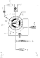
- apparatus for injecting a liquid sample into the analyzing device 43 is denoted by reference numeral 50.
- the apparatus 50 comprises a first liquid circuit 11, a second liquid circuit 12, a valve assembly 30 of the stator/rotor type, and a sample loop 14.
- the first circuit 11 and the second circuit 12 are connected with one another via the valve assembly 30, which comprises a first valve element and a second valve element 32 co-operating with one another and rotatable relative to one another about a rotation axis 33 for switching between different valve positions of the valve assembly.
- the first valve element is the stator of the valve assembly 30, while the second valve element 32 is the rotor of the valve assembly 30.
- Both ends of the sample loop 14 are connected to the valve assembly 30 such that in a first valve position and in a second valve position of the valve assembly, respectively, the sample loop is either part of the first circuit 11 or part of the second circuit 12, respectively.
- the switching of the valve assembly from the second valve position (shown in Fig. 1 ) into the first valve position (shown in Fig. 3 ) is done by rotating the rotor 32 relative to the stator around the rotation axis 33 in the direction of the arrow 37, which arrow is shown in Fig. 1 .
- the switching of the valve assembly from the first valve position (shown in Fig. 3 ) into the second valve position (shown in Fig. 1 ) is done by rotating the rotor 32 relative to the stator around the rotation axis 33 in the direction of the arrow 38, which arrow is shown in Fig. 3 .
- the stator comprises a first valve inlet 1 connected in the first circuit to sample supply means 40, a first valve outlet 2 connected in the first circuit to waste discharge means 41, a second valve inlet 4 connected in the second circuit to mobile phase supply means 42, a second valve outlet 5 connected in the second circuit to the analyzing device 43, a first valve terminal 3 connected to one end of the sample loop 14, and a second valve terminal 6 connected to the other end of the sample loop 14.
- FIGS. 1-3 show a cylinder-piston assembly 44 included in the first liquid circuit 11. This assembly 44 is merely meant as a symbolic illustration of means for displacing liquid in the first liquid circuit 11.
- the rotor 32 comprises a first connection chamber 21, a second connection chamber 22 and a third connection chamber 23.
- these connection chambers are circularly-arched channels, as known in the art, the center of the circular archs being formed by the rotation axis 33.
- the first channel 21 connects the second valve inlet 4 with the second valve outlet 5
- the second channel 22 connects the second terminal 6 with the first valve inlet 1
- the third channel 23 connects the first valve outlet 2 with the first valve terminal 3.
- the first channel 21 connects the first valve terminal 3 with the second valve inlet 4
- the second channel 22 connects the second valve outlet 5 with the second valve terminal 6
- the third channel 23 connects the first valve inlet 1 with the first valve outlet 2.
- stator comprises a third valve outlet 7 and the rotor 32 comprises a fourth connection chamber 24 such that during switching of the valve assembly 30 from the second valve position (shown in Fig. 1 ) into the first valve position (shown in Fig. 3 ) the valve assembly temporarily assumes the intermediate valve position (shown in Fig. 2 ) inbetween the second valve position and the first valve position.
- the fourth chamber 24 connects the first valve terminal 3 with the third valve outlet 7, while in that intermediate valve position the sample loop 14 is neither part of the first circuit 11 nor part of the second circuit 12.
- the third valve outlet 7 is in communication with the outside environment via a hose 34 connected to the third valve outlet 7.
- the third valve outlet 7 and the fourth connection chamber 24 are arranged such that at least during the relative rotative movement about the rotation axis 33 of the two valve elements from the second valve position into the intermediate valve position the fourth chamber 24 continuously is in fluid communication with the third valve outlet 7. More specifically, in the shown example the third valve outlet 7 is arranged such that, as seen in a plane transverse to the rotation axis 33, the rotation axis 33 is enclosed by a cross section of the third valve outlet 7. More specifically, the rotation axis 33 forms the center of said cross section.
- the fourth connection chamber 24 may have various shapes and may be situated at various locations of the rotor 32. In the shown example, the fourth connection chamber 24 has the shape of a channel whose longitudinal direction extends radially relative to the rotation axis 33.
- initializing steps of a method according to the invention can be performed using the apparatus 50 with its HPLC valve assembly 30.
- an initial quantity of the sample is supplied at least into a section of the first circuit 11 between the sample supply means 40 and the first valve inlet 1, and mobile phase is supplied into the second circuit 12 which includes the sample loop 14.
- the liquid pressure in the second circuit 12 is higher than the liquid pressure in the first circuit 11.
- the valve assembly 30 is switched from the second valve position (shown in Fig. 1 ) into the first valve position (shown in Fig. 3 ).
- the valve assembly 30 temporarily assumes the intermediate valve position (shown in Fig. 2 ).
- the high pressure mobile phase in the sample loop 14 will expand and decompress by successively flowing through the first valve terminal 3, the fourth channel 24 and the third valve outlet 7.
- Via the hose 34 some of the mobile phase may be discarded, which is symbolically indicated by means of a depicted droplet in Fig. 2 .
- said decompressed mobile phase is being inserted into the first circuit 11, it will not expand anymore in the first circuit 11.
- valve assembly 30 is switched from the first valve position (shown in Fig. 3 ) into the second valve position (shown in Fig. 1 ) by rotating the rotor 32 relative to the stator in the direction of arrow 38, which arrow is indicated in Fig. 3 .
- the sample in the sample loop is contained in the second circuit 12 then.
- the sample together with the mobile phase is injected from the second circuit 12 into the analyzing device 43.
- first connection chamber 21 such that during the switching of the valve assembly from the second into the first valve position, it connects the second valve inlet 4 with the second valve outlet 5 at an earlier moment than shown in the Figures, for example already at the moment when the intermediate valve position of Fig. 2 is attained.
- This can for example be realized by designing the circularly-arched connection channel 21, as seen in Fig. 1 , with a somewhat extended length from its right hand side in Fig. 1 in the direction of the arrow 37.
- Such an enlarged first connection chamber may be useful when applying an HPLC pump 35 which, during switching of the valve assembly, is continuously in operation.
Landscapes
- Physics & Mathematics (AREA)
- Biochemistry (AREA)
- Health & Medical Sciences (AREA)
- Life Sciences & Earth Sciences (AREA)
- Chemical & Material Sciences (AREA)
- Analytical Chemistry (AREA)
- General Health & Medical Sciences (AREA)
- General Physics & Mathematics (AREA)
- Immunology (AREA)
- Pathology (AREA)
- Fluid Mechanics (AREA)
- Sampling And Sample Adjustment (AREA)
- Automatic Analysis And Handling Materials Therefor (AREA)
Claims (9)
- Procédé pour injecter un échantillon de liquide dans un dispositif d'analyse par CLHP (43), à l'aide d'un appareil (50) qui comporte un premier circuit de liquide (11), un second circuit de liquide (12), un système de vanne (30) du type stator/rotor, et une boucle de prélèvement (14), le premier circuit et le second circuit étant reliés l'un à l'autre par l'intermédiaire du système de vanne qui comprend un premier élément de vanne et un second élément de vanne (32) coopérant l'un avec l'autre et pouvant tourner l'un par rapport à l'autre autour d'un axe de rotation (33) pour venir dans différentes positions de vanne du système de vanne, et les deux extrémités de la boucle de prélèvement étant reliées au système de vanne de telle sorte que, respectivement dans une première position de vanne et une seconde position de vanne, la boucle de prélèvement fasse respectivement partie du premier circuit ou du second circuit, ledit premier élément de vanne comprenant une première entrée (1) de vanne reliée dans le premier circuit à un moyen d'alimentation (40) en échantillon, une première sortie (2) de vanne reliée dans le premier circuit à un moyen de refoulement (41) de résidus, une seconde entrée (4) de vanne reliée dans le second circuit à un second moyen d'alimentation (42) en phase mobile, une deuxième sortie (5) de vanne reliée dans le second circuit au dispositif d'analyse (43), un premier terminal (3) de vanne relié à une première extrémité de la boucle de prélèvement, et un second terminal (6) de vanne relié à l'autre extrémité de la boucle de prélèvement, ledit second élément de vanne comprenant une première chambre de liaison (21), une deuxième chambre de liaison (22) et une troisième chambre de liaison (23), dans la première position de vanne la première chambre reliant la seconde entrée (4) de vanne à la deuxième sortie (5) de vanne, la deuxième chambre reliant le second terminal (6) à la première entrée (1) de terminal et la troisième chambre reliant la première sortie (2) de vanne au premier terminal (3) de vanne, alors que dans la seconde position de vanne la première chambre relie le premier terminal (3) de vanne à la seconde entrée (4) de vanne, la deuxième chambre relie la deuxième sortie (5) de vanne au second terminal (6) de vanne et la troisième chambre relie la première entrée (1) de vanne à la première sortie (2) de vanne ;
le procédé comportant les étapes successives de :- initialisation de l'appareil de telle sorte que le système de vanne soit dans la seconde position de vanne et que, dans cette position, une quantité initiale de l'échantillon soit présente au moins dans une portion du premier circuit entre le moyen d'alimentation en échantillon et la première entrée de vanne, et qu'une phase mobile soit présente dans le second circuit, tandis que la pression du liquide dans le second circuit est plus haute que la pression du liquide dans le premier circuit ;- passage du système de vanne de la seconde position de vanne à la première position de vanne ;- fourniture d'une quantité supplémentaire de l'échantillon au premier circuit dans une mesure telle que la boucle de prélèvement soit au moins partiellement remplie avec l'échantillon ;- passage du système de vanne de la première position de vanne à la seconde position de vanne, à la suite de quoi l'échantillon dans la boucle de prélèvement est contenu dans le second circuit ; et- injection de l'échantillon conjointement avec la phase mobile du second circuit au dispositif d'analyse ;caractérisé en ce que ledit premier élément de vanne comprend une troisième sortie (7) de vanne et ledit second élément de vanne comprend une quatrième chambre de liaison (24) de telle sorte que, pendant le passage du système de vanne de la seconde position de vanne à la première position de vanne, le système de vanne prenne temporairement une position intermédiaire de vanne entre les seconde et première positions de vanne, position intermédiaire de vanne dans laquelle la quatrième chambre relie l'un des premier et second terminaux (3, 6) de vanne à la troisième sortie (7) de vanne, alors que dans cette position intermédiaire de vanne la boucle de prélèvement ne fait partie ni du premier circuit ni du second circuit pour permettre une décompression de la boucle de prélèvement (14) par l'intermédiaire de la quatrième chambre de liaison (24) et de la troisième sortie (7) de vanne. - Procédé selon la revendication 1, dans lequel la troisième sortie (7) de vanne et la quatrième chambre de liaison (24) sont agencées de telle sorte que, au moins pendant le mouvement de rotation relative des deux éléments de vanne autour de l'axe de rotation (33) pour le passage de la seconde position de vanne à la position intermédiaire de vanne, la quatrième chambre soit continuellement en communication fluidique avec la troisième sortie de vanne.
- Procédé selon la revendication 2, dans lequel la troisième sortie (7) de vanne est agencée de telle sorte que, vu dans un plan transversal par rapport à l'axe de rotation (33), l'axe de rotation soit inclus dans une section transversale de la troisième sortie (7) de vanne notamment, par exemple, lorsque l'axe de rotation forme le centre de ladite section transversale.
- Appareil pour injecter un échantillon de liquide dans un dispositif d'analyse par CLHP (43), comportant un premier circuit de liquide (11), un second circuit de liquide (12), un système de vanne (30) du type stator/rotor, et une boucle de prélèvement (14), le premier circuit et le second circuit pouvant être reliés l'un à l'autre par l'intermédiaire du système de vanne qui comprend un premier élément de vanne et un second élément de vanne (32) coopérant l'un avec l'autre et pouvant tourner l'un par rapport à l'autre autour d'un axe de rotation (33) pour venir dans différentes positions de vanne du système de vanne, et les deux extrémités de la boucle de prélèvement pouvant être reliées au système de vanne de telle sorte que, respectivement dans une première position de vanne et une seconde position de vanne du système de vanne, la boucle de prélèvement, lorsqu'elle est ainsi reliée, fasse respectivement soit partie du premier circuit lorsqu'elle est ainsi reliée, soit du second circuit lorsqu'elle est ainsi reliée, ledit premier élément de vanne comprenant une première entrée (1) de vanne, pouvant être reliée dans le premier circuit à un moyen d'alimentation (40) en échantillon, une première sortie (2) de vanne pouvant être reliée dans le premier circuit à un moyen de refoulement (41) de résidus, une seconde entrée (4) de vanne pouvant être reliée dans le second circuit à un second moyen d'alimentation (42) en phase mobile, une deuxième sortie (5) de vanne pouvant être reliée dans le second circuit au dispositif d'analyse (43), un premier terminal (3) de vanne pouvant être relié à une première extrémité de la boucle de prélèvement, et un second terminal (6) de vanne pouvant être relié à l'autre extrémité de la boucle de prélèvement, ledit second élément de vanne comprenant une première chambre de liaison (21), une deuxième chambre de liaison (22) et une troisième chambre de liaison (23), dans la première position de vanne la première chambre reliant la seconde entrée (4) de vanne à la deuxième sortie (5) de vanne, la deuxième chambre reliant le second terminal (6) à la première entrée (1) de terminal et la troisième chambre reliant la première sortie (2) de vanne au premier terminal (3) de vanne, alors que dans la seconde position de vanne la première chambre relie le premier terminal (3) de vanne à la seconde entrée (4) de vanne, la deuxième chambre relie la deuxième sortie (5) de vanne au second terminal (6) de vanne et la troisième chambre relie la première entrée (1) de vanne à la première sortie (2) de vanne ;
caractérisé en ce que ledit premier élément de vanne comprend une troisième sortie (7) de vanne et ledit second élément de vanne comprend une quatrième chambre de liaison (24) de telle sorte que, pendant le passage du système de vanne de la seconde position de vanne à la première position de vanne, le système de vanne prenne temporairement une position intermédiaire de vanne entre les seconde et première positions de vanne, position intermédiaire de vanne dans laquelle la quatrième chambre relie l'un des premier et second terminaux (3, 6) de vanne à la troisième sortie (7) de vanne, alors que dans cette position intermédiaire de vanne la boucle de prélèvement ainsi reliée ne fait partie ni du premier circuit lorsqu'elle est ainsi reliée ni du second circuit lorsqu'elle est ainsi reliée pour permettre une décompression de la boucle de prélèvement (14) par l'intermédiaire de la quatrième chambre de liaison (24) et de la troisième sortie (7) de vanne. - Appareil selon la revendication 4, dans lequel la troisième sortie (7) de vanne et la quatrième chambre de liaison (24) sont agencées de telle sorte que, au moins pendant le mouvement de rotation relative des deux éléments de vanne autour de l'axe de rotation (33) pour le passage de la seconde position de vanne à la position intermédiaire de vanne, la quatrième chambre soit continuellement en communication fluidique avec la troisième sortie de vanne.
- Appareil selon la revendication 5, dans lequel la troisième sortie (7) de vanne est agencée de telle sorte que, vu dans un plan transversal par rapport à l'axe de rotation (33), l'axe de rotation soit inclus dans une section transversale de la troisième sortie (7) de vanne, notamment, par exemple, lorsque l'axe de rotation forme le centre de ladite section transversale.
- Système de vanne (30) du type stator/rotor pour CLHP, comportant un premier élément de vanne et un second élément de vanne (32) coopérant l'un avec l'autre et pouvant tourner l'un par rapport à l'autre autour d'un axe de rotation (33) pour venir dans différentes positions de vanne du système de vanne, ledit premier élément de vanne comprenant une première entrée (1) de vanne, pouvant être reliée dans un premier circuit (11) de liquide à un moyen d'alimentation (40) en échantillon, une première sortie (2) de vanne pouvant être reliée dans le premier circuit à un moyen de refoulement (41) de résidus, une seconde entrée (4) de vanne pouvant être reliée dans un second circuit (12) de liquide à un second moyen d'alimentation (42) en phase mobile, une deuxième sortie (5) de vanne pouvant être reliée dans le second circuit à un dispositif d'analyse par CLHP (43), un premier terminal (3) de vanne pouvant être relié à une première extrémité d'une boucle de prélèvement (14), et un second terminal (6) de vanne pouvant être relié à l'autre extrémité de la boucle de prélèvement, ledit second élément de vanne comprenant une première chambre de liaison (21), une deuxième chambre de liaison (22) et une troisième chambre de liaison (23), dans une première position de vanne du système de vanne la première chambre reliant la seconde entrée (4) de vanne à la deuxième sortie (5) de vanne, la deuxième chambre reliant le second terminal (6) à la première entrée (1) de terminal et la troisième chambre reliant la première sortie (2) de vanne au premier terminal (3) de vanne, alors que dans une seconde position de vanne du système de vanne la première chambre relie le premier terminal (3) de vanne à la seconde entrée (4) de vanne, la deuxième chambre relie la deuxième sortie (5) de vanne au second terminal (6) de vanne et la troisième chambre relie la première entrée (1) de vanne à la première sortie (2) de vanne ;
si bien que les deux extrémités de la boucle de prélèvement peuvent être reliées au système de vanne de telle sorte que, respectivement dans la première position de vanne et dans la seconde position de vanne, la boucle de prélèvement ainsi reliée fasse respectivement partie du premier circuit lorsqu'elle est ainsi reliée ou fasse partie du second circuit lorsqu'elle est ainsi reliée ;
caractérisé en ce que ledit premier élément de vanne comprend une troisième sortie (7) de vanne et ledit second élément de vanne comprend une quatrième chambre de liaison (24) de telle sorte que, pendant le passage du système de vanne de la seconde position de vanne à la première position de vanne, le système de vanne prenne temporairement une position intermédiaire de vanne entre les seconde et première positions de vanne, position intermédiaire de vanne dans laquelle la quatrième chambre relie l'un des premier et second terminaux (3, 6) de vanne à la troisième sortie (7) de vanne, alors que dans cette position intermédiaire de vanne la boucle de prélèvement ainsi reliée ne fait partie ni du premier circuit lorsqu'elle est ainsi reliée ni du second circuit lorsqu'elle est ainsi reliée pour permettre une décompression de la boucle de prélèvement (14) par l'intermédiaire de la quatrième chambre de liaison (24) et de la troisième sortie (7) de vanne. - Système de vanne selon la revendication 7, dans lequel la troisième sortie (7) de vanne et la quatrième chambre de liaison (24) sont agencées de telle sorte que, au moins pendant le mouvement de rotation relative des deux éléments de vanne autour de l'axe de rotation (33) pour le passage de la seconde position de vanne à la position intermédiaire de vanne, la quatrième chambre soit continuellement en communication fluidique avec la troisième sortie de vanne.
- Système de vanne selon la revendication 8, dans lequel la troisième sortie (7) de vanne est agencée de telle sorte que, vu dans un plan transversal par rapport à l'axe de rotation (33), l'axe de rotation soit inclus dans une section transversale de la troisième sortie (7) de vanne, notamment, par exemple, lorsque l'axe de rotation forme le centre de ladite section transversale.
Priority Applications (2)
| Application Number | Priority Date | Filing Date | Title |
|---|---|---|---|
| EP08171387.7A EP2196801B1 (fr) | 2008-12-11 | 2008-12-11 | Procédé et appareil pour injecter un échantillon liquide dans un dispositif d'analyse HPLC, et ensemble de soupape à utiliser avec celui-ci |
| US12/588,840 US8322197B2 (en) | 2008-12-11 | 2009-10-29 | Method and apparatus for injecting a liquid sample in an HPLC analyzing device, and valve assembly for use therein |
Applications Claiming Priority (1)
| Application Number | Priority Date | Filing Date | Title |
|---|---|---|---|
| EP08171387.7A EP2196801B1 (fr) | 2008-12-11 | 2008-12-11 | Procédé et appareil pour injecter un échantillon liquide dans un dispositif d'analyse HPLC, et ensemble de soupape à utiliser avec celui-ci |
Publications (2)
| Publication Number | Publication Date |
|---|---|
| EP2196801A1 EP2196801A1 (fr) | 2010-06-16 |
| EP2196801B1 true EP2196801B1 (fr) | 2017-08-23 |
Family
ID=40578555
Family Applications (1)
| Application Number | Title | Priority Date | Filing Date |
|---|---|---|---|
| EP08171387.7A Active EP2196801B1 (fr) | 2008-12-11 | 2008-12-11 | Procédé et appareil pour injecter un échantillon liquide dans un dispositif d'analyse HPLC, et ensemble de soupape à utiliser avec celui-ci |
Country Status (2)
| Country | Link |
|---|---|
| US (1) | US8322197B2 (fr) |
| EP (1) | EP2196801B1 (fr) |
Families Citing this family (17)
| Publication number | Priority date | Publication date | Assignee | Title |
|---|---|---|---|---|
| DE102008006266B4 (de) | 2008-01-25 | 2011-06-09 | Dionex Softron Gmbh | Probengeber für die Flüssigkeitschromatographie, insbesondere für die Hochleistungsflüssigkeitschromatographie |
| CA2764047C (fr) * | 2009-06-03 | 2016-12-13 | Agilent Technologies, Inc. | Injecteur d'echantillon pourvu d'un dispositif doseur pour equilibrer les differences de pression dans un etat de valve intermediaire |
| US8944102B1 (en) * | 2011-03-07 | 2015-02-03 | Elemental Scientific, Inc. | Gas burst injection valve |
| CN102808971B (zh) * | 2012-01-09 | 2014-09-03 | 加拿大博朗科技有限公司 | 一种流体选择阀 |
| CN103134889B (zh) * | 2013-01-25 | 2015-03-04 | 中山大学 | 在线富集-分步聚焦进样-超高效液相色谱联用系统及应用 |
| WO2014175251A1 (fr) * | 2013-04-22 | 2014-10-30 | 積水メディカル株式会社 | Soupape de commutation pour dispositif d'analyse de type d'écoulement |
| US9541207B1 (en) | 2014-02-03 | 2017-01-10 | Elemental Scientific, Inc. | Valve assembly with bottom bypass ports |
| US9752691B1 (en) | 2014-07-03 | 2017-09-05 | Elemental Scientific, Inc. | Valve for controlled shuttle of liquid into microtiter plates and mixing |
| JP6421661B2 (ja) * | 2015-03-19 | 2018-11-14 | 株式会社島津製作所 | 示差屈折率検出器及び液体クロマトグラフ |
| DE202016100451U1 (de) | 2015-06-25 | 2016-02-16 | Dionex Softron Gmbh | Probengeber für die Flüssigkeitschromatographie, insbesondere für die Hochleistungsflüssigkeitschromatographie |
| DE102017101629A1 (de) * | 2017-01-27 | 2018-08-02 | Agilent Technologies, Inc. - A Delaware Corporation - | Fluidventil mit goldhaltiger und/oder platinhaltiger Beschichtung |
| JP6992810B2 (ja) * | 2017-07-04 | 2022-01-13 | 株式会社島津製作所 | オートサンプラ及び流体クロマトグラフ |
| US11441978B1 (en) * | 2018-04-12 | 2022-09-13 | Elemental Scientific, Inc. | Automatic evaporative sample preparation |
| WO2020033850A1 (fr) * | 2018-08-10 | 2020-02-13 | Nathan Saetveit | Préconcentration d'échantillons de fluide avec introduction alternée dans une double boucle |
| JP6647380B1 (ja) * | 2018-12-26 | 2020-02-14 | 日本分光株式会社 | 試料注入装置 |
| US11835496B2 (en) | 2019-12-23 | 2023-12-05 | Waters Technologies Corporation | Sample metering and injection for liquid chromatography |
| CN114184723A (zh) * | 2021-12-30 | 2022-03-15 | 泰渡生物科技(苏州)有限公司 | 转动阀、上样装置及层析实验系统 |
Family Cites Families (30)
| Publication number | Priority date | Publication date | Assignee | Title |
|---|---|---|---|---|
| US2571000A (en) * | 1948-05-01 | 1951-10-09 | Mckays Company | Water softening system and apparatus |
| US2979079A (en) * | 1957-12-30 | 1961-04-11 | Turak Anthony | Plural dispensing valve |
| US3080887A (en) * | 1961-03-06 | 1963-03-12 | Modernair Corp | Fluid pressure-operated multi-way valve |
| US3514210A (en) * | 1968-01-15 | 1970-05-26 | Jiri Hrdina | Device for programmed drawing off of gas bubbles from a measuring cell separator and the liquid from the extinction cell space |
| US3975946A (en) * | 1974-02-27 | 1976-08-24 | Micromeritics Instrument Corporation | Liquid chromatography sample measuring and introducing apparatus |
| US4059009A (en) * | 1976-09-10 | 1977-11-22 | Micromeritics Instrument Corporation | Liquid chromatography system |
| US4243071A (en) * | 1978-08-23 | 1981-01-06 | Altex Scientific, Inc. | Sample injection valve |
| US4444066A (en) * | 1981-06-29 | 1984-04-24 | Beckman Instruments, Inc. | High pressure sample injector valve |
| US4506558A (en) * | 1983-03-03 | 1985-03-26 | Rheodyne Incorporated | Injector with minimal flow-interrupt transient |
| US4625569A (en) * | 1984-01-17 | 1986-12-02 | Toyo Soda Manufacturing Co., Ltd. | Liquid injection device |
| US5294052A (en) * | 1986-07-14 | 1994-03-15 | Glas-Craft, Inc. | Fluid dispensing system |
| JPH0389142A (ja) * | 1989-08-31 | 1991-04-15 | Nikkiso Co Ltd | ガス流路切り替え装置 |
| DE3934699A1 (de) * | 1989-10-18 | 1991-04-25 | Bodenseewerk Perkin Elmer Co | Dosiereinrichtung fuer analysengeraete |
| US6012487A (en) | 1997-03-10 | 2000-01-11 | Brian A. Hauck | Prime purge injection valve or multi-route selections valve |
| US5937903A (en) * | 1997-10-15 | 1999-08-17 | Pac-Fab, Inc. | High performance diverter valve |
| US6290909B1 (en) * | 2000-04-13 | 2001-09-18 | Sandia Corporation | Sample injector for high pressure liquid chromatography |
| ATE421691T1 (de) * | 2000-11-13 | 2009-02-15 | Ctc Analytics Ag | Probenaufgabeventil für hplc-geräte |
| DE20211295U1 (de) * | 2001-02-16 | 2002-12-12 | Continental Aktiengesellschaft, 30165 Hannover | Gerät zum Abdichten und Aufpumpen eines aufblähbaren Objekts |
| US6382035B1 (en) * | 2001-04-02 | 2002-05-07 | Rheodyne, Lp | Multi-valving sample injection apparatus |
| JP4459633B2 (ja) * | 2004-01-13 | 2010-04-28 | ダイセル化学工業株式会社 | 試料の注入方法及び注入装置 |
| US20060045810A1 (en) | 2004-08-27 | 2006-03-02 | Konstantin Choikhet | Sample injector for liquid analysis |
| US8047060B2 (en) * | 2005-01-31 | 2011-11-01 | Waters Technologies Corporation | Method and apparatus for sample injection in liquid chromatography |
| JP2007232977A (ja) * | 2006-02-28 | 2007-09-13 | Toshiba Corp | デコーダ回路およびこのデコーダ回路を用いる液晶駆動装置 |
| WO2008005845A2 (fr) | 2006-06-30 | 2008-01-10 | Waters Investments Limited | atténuation des effets de décompression par introduction d'échantillon dans la chromatographie liquide À haute pression |
| KR100885267B1 (ko) * | 2007-05-09 | 2009-02-23 | 삼성전기주식회사 | 원심력과 관성을 이용한 시료 분석 장치 |
| US8225817B2 (en) * | 2007-05-15 | 2012-07-24 | Ge Healthcare Bio-Sciences Ab | Flow distributing valve |
| DE102007059651B4 (de) * | 2007-12-10 | 2017-05-24 | Dionex Softron Gmbh | Probengeber für die Hochleistungsflüssigkeitschromatographie |
| DE102008006266B4 (de) * | 2008-01-25 | 2011-06-09 | Dionex Softron Gmbh | Probengeber für die Flüssigkeitschromatographie, insbesondere für die Hochleistungsflüssigkeitschromatographie |
| US7987701B2 (en) * | 2008-05-07 | 2011-08-02 | University Of Memphis Research Foundation | Real-time, on-line analysis for the quantification of total haloacetic acid and trihalomethane species in drinking water supplies |
| CA2764047C (fr) * | 2009-06-03 | 2016-12-13 | Agilent Technologies, Inc. | Injecteur d'echantillon pourvu d'un dispositif doseur pour equilibrer les differences de pression dans un etat de valve intermediaire |
-
2008
- 2008-12-11 EP EP08171387.7A patent/EP2196801B1/fr active Active
-
2009
- 2009-10-29 US US12/588,840 patent/US8322197B2/en active Active
Non-Patent Citations (1)
| Title |
|---|
| None * |
Also Published As
| Publication number | Publication date |
|---|---|
| US8322197B2 (en) | 2012-12-04 |
| US20100147086A1 (en) | 2010-06-17 |
| EP2196801A1 (fr) | 2010-06-16 |
Similar Documents
| Publication | Publication Date | Title |
|---|---|---|
| EP2196801B1 (fr) | Procédé et appareil pour injecter un échantillon liquide dans un dispositif d'analyse HPLC, et ensemble de soupape à utiliser avec celui-ci | |
| US8382979B2 (en) | Liquid chromatograph system | |
| EP3008463B1 (fr) | Rinsage d'un appareil de dosage par un solvent provenant d'un circuit analytique d'un système de séparation de fluide, ledit appareil de dosage etant commutable entre differents circuits d'écoulement | |
| CA2676171C (fr) | Vanne rotative pour l'injection d'echantillon | |
| JP5492985B2 (ja) | 中間バルブ状態における圧力差を均衡させる計量デバイスを有するサンプルインジェクター | |
| US11543391B2 (en) | Sample pre-compression valve for liquid chromatography | |
| US9945762B2 (en) | Apparatus and method for introducing sample into a separation unit of a chromatography system without disrupting a mobile phase | |
| US8522627B2 (en) | Automatic sampler for liquid chromatograph | |
| EP2524213B1 (fr) | Support et lavage d'aiguille pour port d'injection | |
| US9115815B2 (en) | Variable-volume injection valve | |
| CN105308449A (zh) | 将样品储存器并联联接在流动相驱动器和分离单元之间的hplc进样 | |
| CN104265952A (zh) | 一种八通阀及一种基于八通阀的层析系统 | |
| CN110621993B (zh) | 自动取样器及流体色谱仪 | |
| US11573210B2 (en) | Dual mode sample manager | |
| EP3519807B1 (fr) | Système pour soumettre un échantillon à une analyse chromatographique | |
| EP2061420A1 (fr) | Dispositif de lavage pour injecteurs de chromatographie en phase liquide |
Legal Events
| Date | Code | Title | Description |
|---|---|---|---|
| PUAI | Public reference made under article 153(3) epc to a published international application that has entered the european phase |
Free format text: ORIGINAL CODE: 0009012 |
|
| AK | Designated contracting states |
Kind code of ref document: A1 Designated state(s): AT BE BG CH CY CZ DE DK EE ES FI FR GB GR HR HU IE IS IT LI LT LU LV MC MT NL NO PL PT RO SE SI SK TR |
|
| AX | Request for extension of the european patent |
Extension state: AL BA MK RS |
|
| 17P | Request for examination filed |
Effective date: 20101007 |
|
| 17Q | First examination report despatched |
Effective date: 20101103 |
|
| AKX | Designation fees paid |
Designated state(s): DE FR GB |
|
| GRAP | Despatch of communication of intention to grant a patent |
Free format text: ORIGINAL CODE: EPIDOSNIGR1 |
|
| RIC1 | Information provided on ipc code assigned before grant |
Ipc: G01N 35/10 20060101ALN20170315BHEP Ipc: G01N 30/20 20060101AFI20170315BHEP |
|
| INTG | Intention to grant announced |
Effective date: 20170330 |
|
| RIN1 | Information on inventor provided before grant (corrected) |
Inventor name: KOSTER, EMILE HERMANNUS MAARTEN Inventor name: POOT, RUDOLF HERMAN ROBERT Inventor name: HALMINGH, OTTO Inventor name: GIJLERS, HERMANNUS GEERT |
|
| GRAS | Grant fee paid |
Free format text: ORIGINAL CODE: EPIDOSNIGR3 |
|
| GRAA | (expected) grant |
Free format text: ORIGINAL CODE: 0009210 |
|
| AK | Designated contracting states |
Kind code of ref document: B1 Designated state(s): DE FR GB |
|
| REG | Reference to a national code |
Ref country code: GB Ref legal event code: FG4D |
|
| REG | Reference to a national code |
Ref country code: DE Ref legal event code: R096 Ref document number: 602008051734 Country of ref document: DE |
|
| REG | Reference to a national code |
Ref country code: FR Ref legal event code: PLFP Year of fee payment: 10 |
|
| REG | Reference to a national code |
Ref country code: DE Ref legal event code: R097 Ref document number: 602008051734 Country of ref document: DE |
|
| PLBE | No opposition filed within time limit |
Free format text: ORIGINAL CODE: 0009261 |
|
| STAA | Information on the status of an ep patent application or granted ep patent |
Free format text: STATUS: NO OPPOSITION FILED WITHIN TIME LIMIT |
|
| 26N | No opposition filed |
Effective date: 20180524 |
|
| PGFP | Annual fee paid to national office [announced via postgrant information from national office to epo] |
Ref country code: GB Payment date: 20231220 Year of fee payment: 16 |
|
| PGFP | Annual fee paid to national office [announced via postgrant information from national office to epo] |
Ref country code: FR Payment date: 20231221 Year of fee payment: 16 Ref country code: DE Payment date: 20231214 Year of fee payment: 16 |