EP2196606B1 - Vehicle door latch device - Google Patents
Vehicle door latch device Download PDFInfo
- Publication number
- EP2196606B1 EP2196606B1 EP08837565.4A EP08837565A EP2196606B1 EP 2196606 B1 EP2196606 B1 EP 2196606B1 EP 08837565 A EP08837565 A EP 08837565A EP 2196606 B1 EP2196606 B1 EP 2196606B1
- Authority
- EP
- European Patent Office
- Prior art keywords
- latch
- pole
- helical
- vehicle door
- shaft portion
- Prior art date
- Legal status (The legal status is an assumption and is not a legal conclusion. Google has not performed a legal analysis and makes no representation as to the accuracy of the status listed.)
- Not-in-force
Links
- 230000004308 accommodation Effects 0.000 claims description 2
- 238000010586 diagram Methods 0.000 description 3
- 239000002184 metal Substances 0.000 description 2
- 230000000717 retained effect Effects 0.000 description 2
- 239000011347 resin Substances 0.000 description 1
- 229920005989 resin Polymers 0.000 description 1
Images


Classifications
-
- E—FIXED CONSTRUCTIONS
- E05—LOCKS; KEYS; WINDOW OR DOOR FITTINGS; SAFES
- E05B—LOCKS; ACCESSORIES THEREFOR; HANDCUFFS
- E05B85/00—Details of vehicle locks not provided for in groups E05B77/00 - E05B83/00
- E05B85/20—Bolts or detents
- E05B85/24—Bolts rotating about an axis
- E05B85/26—Cooperation between bolts and detents
-
- E—FIXED CONSTRUCTIONS
- E05—LOCKS; KEYS; WINDOW OR DOOR FITTINGS; SAFES
- E05B—LOCKS; ACCESSORIES THEREFOR; HANDCUFFS
- E05B77/00—Vehicle locks characterised by special functions or purposes
- E05B77/36—Noise prevention; Anti-rattling means
-
- E—FIXED CONSTRUCTIONS
- E05—LOCKS; KEYS; WINDOW OR DOOR FITTINGS; SAFES
- E05B—LOCKS; ACCESSORIES THEREFOR; HANDCUFFS
- E05B15/00—Other details of locks; Parts for engagement by bolts of fastening devices
- E05B15/04—Spring arrangements in locks
- E05B2015/0403—Wound springs
- E05B2015/0406—Wound springs wound in a cylindrical shape
- E05B2015/041—Wound springs wound in a cylindrical shape loaded perpendicular to cylinder axis
-
- E—FIXED CONSTRUCTIONS
- E05—LOCKS; KEYS; WINDOW OR DOOR FITTINGS; SAFES
- E05B—LOCKS; ACCESSORIES THEREFOR; HANDCUFFS
- E05B85/00—Details of vehicle locks not provided for in groups E05B77/00 - E05B83/00
- E05B85/02—Lock casings
-
- Y—GENERAL TAGGING OF NEW TECHNOLOGICAL DEVELOPMENTS; GENERAL TAGGING OF CROSS-SECTIONAL TECHNOLOGIES SPANNING OVER SEVERAL SECTIONS OF THE IPC; TECHNICAL SUBJECTS COVERED BY FORMER USPC CROSS-REFERENCE ART COLLECTIONS [XRACs] AND DIGESTS
- Y10—TECHNICAL SUBJECTS COVERED BY FORMER USPC
- Y10T—TECHNICAL SUBJECTS COVERED BY FORMER US CLASSIFICATION
- Y10T292/00—Closure fasteners
- Y10T292/08—Bolts
- Y10T292/1043—Swinging
- Y10T292/1044—Multiple head
- Y10T292/1045—Operating means
- Y10T292/1047—Closure
Definitions
- the present invention relates to a vehicle door latch device.
- FIG. 6 is a diagram showing the structure and operation of a vehicle door latch device disclosed in Patent Document 1.
- the vehicle door latch device includes a latch 91, a pole 92, and a helical torsion spring 94.
- the latch 91 is rotatably supported by a housing provided in a vehicle door and receives a striker 90 on the vehicle body.
- the pole 92 is rotatably supported by the housing, and can be fitted to the latch 91 so as to limit the rotation of the latch 91.
- the helical torsion spring 94 always urges the pole 92 to rotate in a direction to cause the pole 92 to engage with the latch 91.
- the housing has a stopper 93, and the pole 92 is engageable with the pole 92.
- the pole 92 includes a block-like main body portion 92a and a shaft portion 92b extending from a center portion of the main body portion 92a.
- the shaft portion 92b is passed through a shaft receiving hole 95 formed in the housing, so that the pole 92 is rotatably supported by the housing.
- the helical torsion spring 94 includes a helical portion 94a, and first and second engaging legs 94b, 94c, which extend radially outward relative to the helical portion 94a.
- the shaft portion 92b is passed through the helical portion 94a at a position where the shaft portion 92b does not interfere with the housing.
- the first engaging leg 94b is engaged with the pole 92, and the second engaging leg 94c is engaged with an engaging portion 96 provided in the housing.
- the helical portion 94a of the helical torsion spring 94 is mounted about the shaft portion 92b of the pole 92 so as to be coaxial with the shaft portion 92b, so that the operation reliability of the pole 92 is improved.
- the urging force urges the shaft portion 92b of the pole 92 toward the latch 91, thereby causing the shaft portion 92b to contact the inner circumferential surface of the shaft receiving hole 95.
- the shaft portion 92b receives an urging force (indicated by thin arrows), which is a reactive force against the above described urging force, through the helical portion 94a.
- the pole 92 is arranged at an eccentric position in the shaft receiving hole 95 such that the clearance C between the shaft portion 92b and the inner circumferential surface of the shaft receiving hole 95 is zero at the top, and the clearance C is greater at the bottom.
- the pole 92 is released from the latch 91 immediately after a half-meshed state is achieved, where the latch 91 draws in the striker 90 halfway, the pole 92 is, as in the initial state, arranged at an eccentric position in the shaft receiving hole 95 such that the clearance C between the shaft portion 92b and the inner circumferential surface of the shaft receiving hole 95 is zero at the top, and the clearance C is greater at the bottom.
- Patent Document 2 discloses one example of known vehicle door latch devices that reduce such hammering noise.
- the shaft portion of pole is rotatably supported by a cylindrical projecting wall formed on the housing, and the helical portion of the helical torsion spring is held about the projecting wall.
- the helical portion since the urging force of the helical portion does not act on the shaft portion, hammering noise due to movement of the shaft portion as described above is not produced.
- the helical portion needs have a large diameter. This inevitably causes another problem, namely, an increased size of the entire device.
- a vehicle door latch device including a housing, a latch, a pole, a helical torsion spring, and a projecting wall.
- the housing is structured to be provided in a vehicle door.
- the latch rotatably is supported by the housing.
- a striker provided in the vehicle body can be fitted to the latch.
- the pole has a shaft portion rotatably supported by the housing. The pole is engageable with the latch to restrict rotation of the latch.
- the helical torsion spring has a helical portion through which the shaft portion is passed, a first engaging leg extending radially outward in relation to the helical portion, and a second engaging leg extending radially outward in relation to the helical portion.
- the first engaging leg is engaged with the pole, and the second engaging leg is engaged with the housing.
- the helical torsion spring always urges the pole to rotate to an engagement position where the pole can be engaged with the latch.
- the projecting wall is formed in the housing and contacts an outer circumferential surface of the helical portion.
- a vehicle door latch device includes a body 11, which is, for example, made of resin, a metal base plate 12, and a metal sub-base plate 13.
- the base plate 12 and the sub-base plate 13 sandwich the body 11 and form an accommodation space.
- the body 11, the base plate 12, and the sub-base plate 13 are integrally assembled to form a housing attached to a vehicle door.
- a striker 10 provided in the vehicle body (refer to Fig. 1 )
- the body 11 has a guide portion 11 a having a channel-like cross section
- the base plate 12 has a rectangular guide hole 12a.
- a latch 14 is accommodated between the body 11 and the base plate 12.
- the distal end of a support pin 15 is passed through the sub-base plate 13, the body 11, the latch 14, and the base plate 12 in this order, and is retained by the base plate 12.
- the latch 14 is supported to be rotatable about the support pin 15.
- the latch 14 is formed like scissors and has an engaging groove 14a, which is meshed with the striker 10 by drawing in the striker 10 when receiving the striker 10.
- a torsion coil spring (urging member) 16 which is arranged between the body 11 and the latch 14, has a coil portion, a first end, and a second end.
- the coil portion is arranged coaxially about the support pin 15, and the first and second ends are engaged with the latch 14 and the body 11 (housing), respectively.
- the torsion coil spring 16 applies a predetermined force to the latch 14 so as to limit rotation of the latch 14.
- the latch 14 rotates, the latch 14 is urged by the force and is rotated to return to the original position. Therefore, when the latch 14 is released from the surrounding members, for example, when the vehicle door is open, the torsion coil spring 16 always urges the latch 14 to rotate such that the engaging groove 14a faces the direction of entry of the striker 10 (see Fig. 5 ). At this time, the latch 14 is held such that the opening of the engaging groove 14a is oriented in the same direction as the openings of the guide portion 11a and the guide hole 12a.
- a pole 17 is provided between the base plate 12 and the sub-base plate 13.
- the pole 17 includes a block-like main body portion 17a and a shaft portion 17b.
- the main body portion 17a is accommodated between the body 11 and the base plate 12 and below the latch 14, and the shaft portion 17b extends from a center of the main body portion 17a.
- the distal end of the shaft portion 17b is passed through the body 11, the sub-base plate 13, and a center of a lift lever 18 in this order, and is fitted and retained in the center of the lift lever 18.
- the lift lever 18 rotates integrally with the pole 17.
- the shaft portion 17b is passed through the base plate 12, so that the pole 17 is rotatably supported by the base plate 12 (housing). In this manner, the pole 17, which is rotatably supported by the housing, engages the latch 14 with the main body portion 17a, thereby restricting rotation of the latch 14. Rotation of the latch 14 is restricted when the latch 14 is meshed with the striker 10, for example, when the vehicle door is closed. When the restriction of the rotation by the pole 17 is cancelled, the latch 14, which is meshed with the striker 10, is urged by the torsion coil spring 16 and is rotated to return to a position where the engaging groove 14a faces in the direction of entry of the striker 10, that is, to a position where the striker 10 can exit the engaging groove 14a.
- the base plate 12 has a circular shaft receiving hole 12b, which serves as a support hole.
- the shaft portion 17b of the pole 17 is rotatably supported by the shaft receiving hole 12b (the base plate 12) so that its outer circumferential surface slides on the inner circumferential surface of the shaft receiving hole 12b.
- a clearance C exists between the outer circumferential surface of the shaft portion 17b and the inner circumferential surface of the shaft receiving hole 12b. The clearance C allows the shaft portion 17b to rotate relative to the shaft receiving hole 12b.
- a similar shaft receiving hole may be formed in the sub-base plate 13.
- the helical torsion spring 19 includes a helical portion (coil portion) 19a, through which the shaft portion 17b of the pole 17 is passed.
- the helical portion 19a is located in a space formed between the body 11 and the sub-base plate 13 and below the guide portion 11 a.
- the helical torsion spring 19 includes a first engaging leg 19b and a second engaging leg 19c.
- the first engaging leg 19b extends radially outward in relation to the helical portion 19a to be passed through the body 11 and engaged with the main body portion 17a.
- the second engaging leg 19c also extends radially outward in relation to the helical portion 19a to be engaged with an engaging portion 13a of the sub-base plate 13.
- the first and second engaging legs 19b, 19c extend in opposite directions from the helical portion 19a. As shown in Fig.
- the helical torsion spring 19 always urges the main body portion 17a to rotate in the counterclockwise direction as viewed in the drawing, or in a direction to engage with the latch 14, so that the main body portion 17a is engaged with a stopper 20 provided on the body 11.
- the pole 17 can be engaged with the latch 14 by causing the main body portion 17a to contact the latch 14 meshed with the striker 10.
- the body 11 has a projecting wall 21 located below the helical portion 19a to be pressed against the outer circumferential surface of the helical portion 19a.
- the projecting wall 21 projects in a direction opposite to the base plate 12.
- the projecting wall 21 extends substantially parallel with the shaft portion 17b.
- a vehicle door is in an openable state (hereinafter, referred to as "initial state") and the striker 10 is not meshed with the latch 14, the main body portion 17a of the pole 17 contacts the stopper 20 at a location marked by sign o.
- the main body portion 17a receives, through the first engaging leg 19b of the helical torsion spring 19, a force (indicated by thick arrows) that rotates the pole 17 counterclockwise as viewed in the drawings about a portion that contacts the stopper 20 as a fulcrum.
- the urging force urges the shaft portion 17b of the pole 17 toward the latch 14, thereby causing the shaft portion 17b to contact the inner circumferential surface of the shaft receiving hole 12b.
- the projecting wall 21 receives an urging force (indicated by thin arrows), which is a reactive force against the above described urging force, through the helical portion 19a. That is, the shaft portion 17b of the pole 17 does not receive any urging force through the helical portion 19a. Therefore, as shown in the left lower part of Fig.
- the pole 17 is arranged at an eccentric position in the shaft receiving hole 12b such that the clearance C between the shaft portion 17b and the inner circumferential surface of the shaft receiving hole 12b is zero at the top, and the clearance C is greater at the bottom.
- the pole 17 is at such a position in the shaft receiving hole 12b that the clearance C between the shaft portion 17b and the inner circumferential surface of the shaft receiving hole 12b is still zero at the top and is greater than zero at the bottom. That is, when the pole 17 is being rotated against the urging force of the helical torsion spring 19, the projecting wall 21 is held in contact with the outer circumferential of the helical portion 19a. In this manner, the projecting wall 21 maintains the contacting state of the outer circumferential surface of the shaft portion 17b and the inner circumferential surface of the shaft receiving hole 12b and the state of the clearance C substantially to the same as the initial state.
- the projecting wall 21 maintains a state where the outer circumferential surface of the shaft portion 17b and the inner circumferential surface of the shaft receiving hole 12b contact each other.
- the pole 17 is released from the latch 14 again immediately after the latch 14 draws in the striker 10 halfway, and the latch 14 is in a half-meshed state, the pole 17 returns to the initial state.
- the pole 17 is at such a position in the shaft receiving hole 12b that the clearance C between the shaft portion 17b and the inner circumferential surface of the shaft receiving hole 12b is still zero at the top and is greater than zero at the bottom.
- the latch 14 is urged by the torsion coil spring 16 and acts to rotate to return to the original position.
- the pole 17 causes the latch 14 to engage with the main body portion 17a, so that the rotation of the latch 14 is restricted and the latch 14 is in the half-meshed state with the striker 10. The vehicle door is thus maintained half-closed.
- the movement of the shaft portion 17b within the shaft receiving hole 12b when the vehicle door is manipulated to be closed, that is, changes in the clearance C is small. Therefore, the shaft portion 17b, which moves within the shaft receiving hole 12b, is prevented from hitting the inner circumferential surface of the shaft receiving hole 12b. Unnatural hammering noise is thus reduced.
- the lift lever 18 rotates integrally with the pole 17, thereby cancelling the restriction of the rotation of the latch 14 by the pole 17.
- the latch 14, which is meshed with the striker 10 is urged by the torsion coil spring 16 and is rotated to return to a position where the engaging groove 14a faces in the direction of entry of the striker 10, that is, to a position where the striker 10 can exit the engaging groove 14a.
- the vehicle door is then in the openable state.
- the projecting wall 21, which contacts the outer circumferential wall of the helical portion 19a, is located at a part of the lower portion of the shaft receiving hole 12b.
- the projecting wall 21 may be formed to cylindrically project so as to encompass the shaft receiving hole 12b.
- the projecting wall 21 may be formed to contact any part of the helical portion 19a in any manner.
Description
- The present invention relates to a vehicle door latch device.
- Conventionally, an example of a vehicle door latch device as described in
Patent Document 1 is known.Fig. 6 is a diagram showing the structure and operation of a vehicle door latch device disclosed inPatent Document 1. The vehicle door latch device includes alatch 91, apole 92, and ahelical torsion spring 94. Thelatch 91 is rotatably supported by a housing provided in a vehicle door and receives astriker 90 on the vehicle body. Thepole 92 is rotatably supported by the housing, and can be fitted to thelatch 91 so as to limit the rotation of thelatch 91. Thehelical torsion spring 94 always urges thepole 92 to rotate in a direction to cause thepole 92 to engage with thelatch 91. The housing has astopper 93, and thepole 92 is engageable with thepole 92. - The
pole 92 includes a block-likemain body portion 92a and ashaft portion 92b extending from a center portion of themain body portion 92a. Theshaft portion 92b is passed through ashaft receiving hole 95 formed in the housing, so that thepole 92 is rotatably supported by the housing. - The
helical torsion spring 94 includes ahelical portion 94a, and first and secondengaging legs helical portion 94a. Theshaft portion 92b is passed through thehelical portion 94a at a position where theshaft portion 92b does not interfere with the housing. The firstengaging leg 94b is engaged with thepole 92, and the secondengaging leg 94c is engaged with an engagingportion 96 provided in the housing. - In this manner, the
helical portion 94a of thehelical torsion spring 94 is mounted about theshaft portion 92b of thepole 92 so as to be coaxial with theshaft portion 92b, so that the operation reliability of thepole 92 is improved. - In the vehicle door latch device disclosed in
Patent Document 1, when a vehicle door is in an openable state (hereinafter, referred to as "initial state") and thestriker 90 is not meshed with thelatch 91, themain body portion 92a of thepole 92 contacts thestopper 93 at a location marked by sign o. At this time, themain body portion 92a receives, through the firstengaging leg 94b of thehelical torsion spring 94, a force (indicated by thick arrows) that rotates thepole 92 counterclockwise as viewed in the drawings about a portion that contacts thestopper 93 as a fulcrum. The urging force urges theshaft portion 92b of thepole 92 toward thelatch 91, thereby causing theshaft portion 92b to contact the inner circumferential surface of theshaft receiving hole 95. At this time, theshaft portion 92b receives an urging force (indicated by thin arrows), which is a reactive force against the above described urging force, through thehelical portion 94a. In this state, as shown in the left lower part ofFig. 6 in an exaggerated manner, thepole 92 is arranged at an eccentric position in theshaft receiving hole 95 such that the clearance C between theshaft portion 92b and the inner circumferential surface of theshaft receiving hole 95 is zero at the top, and the clearance C is greater at the bottom. - When the vehicle door is manipulated to be closed, rotation of the
latch 91 accompanying the entry of thestriker 90 presses thepole 92 against thelatch 91, so that thepole 92 is rotated clockwise while acting against the urging force of thehelical torsion spring 94. The part of thepole 92 that contacts thelatch 91 is indicated by the sign o. At this time, themain body portion 92a of thepole 92 is pressed downward by thelatch 91 at the contact position. Also, the urging force (indicated by thin arrows) acting on theshaft portion 92b through thehelical portion 94a is greater than the initial state, and the urging force presses thepole 92 downward. This arranges thepole 92 eccentrically in theshaft receiving hole 95, such that the clearance C between theshaft portion 92b and the inner circumferential surface of theshaft receiving hole 95 is greater at the top. - Then, when the
pole 92 is released from thelatch 91 immediately after a half-meshed state is achieved, where thelatch 91 draws in thestriker 90 halfway, thepole 92 is, as in the initial state, arranged at an eccentric position in theshaft receiving hole 95 such that the clearance C between theshaft portion 92b and the inner circumferential surface of theshaft receiving hole 95 is zero at the top, and the clearance C is greater at the bottom. - When the
pole 92 returns to the position of the initial state, theshaft portion 92b, which moves in theshaft receiving hole 95, hits the inner circumferential surface of theshaft receiving hole 95 and produces unnatural hammering noise, which disturbs the user in some cases. Specifically, when the vehicle door is manipulated to be closed, cheap high pitched sound has been observed to be mixed in deep sound, which is normally produced when the vehicle door is closed. - Patent Document 2 discloses one example of known vehicle door latch devices that reduce such hammering noise. In this vehicle door latch device, the shaft portion of pole is rotatably supported by a cylindrical projecting wall formed on the housing, and the helical portion of the helical torsion spring is held about the projecting wall. In this configuration, since the urging force of the helical portion does not act on the shaft portion, hammering noise due to movement of the shaft portion as described above is not produced. However, to provide the cylindrical projecting wall between the shaft portion and the helical portion, the helical portion needs have a large diameter. This inevitably causes another problem, namely, an increased size of the entire device.
- Patent Document 1: Japanese Laid-Open Patent Publication No.
2002-129809 - Patent Document 2: Japanese Registered Utility Model No.
2519638 Fig. 3 )JP 2003 293638A JP 2002 220960A claim 1 of the present application. - Accordingly, it is an objective of the present invention to provide a vehicle door latch device that reduces unnatural hammering noise produced when a vehicle door is manipulated to be closed, without increasing the size of the device.
- To achieve the foregoing objective and in accordance with one aspect of the present invention, a vehicle door latch device including a housing, a latch, a pole, a helical torsion spring, and a projecting wall is provided. The housing is structured to be provided in a vehicle door. The latch rotatably is supported by the housing. A striker provided in the vehicle body can be fitted to the latch. The pole has a shaft portion rotatably supported by the housing. The pole is engageable with the latch to restrict rotation of the latch. The helical torsion spring has a helical portion through which the shaft portion is passed, a first engaging leg extending radially outward in relation to the helical portion, and a second engaging leg extending radially outward in relation to the helical portion. The first engaging leg is engaged with the pole, and the second engaging leg is engaged with the housing. The helical torsion spring always urges the pole to rotate to an engagement position where the pole can be engaged with the latch. The projecting wall is formed in the housing and contacts an outer circumferential surface of the helical portion.
-
-
Fig. 1 is an exploded perspective view illustrating a vehicle door latch device according to first embodiment of the present invention; -
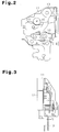
Fig. 2 is an elevational view showing the vehicle door latch device ofFig. 1 , as seen from the front of the vehicle; -
Fig. 3 is an elevational view of the vehicle door latch device ofFig. 1 , as seen from the outside of the vehicle toward the vehicle door; -
Fig. 4 is a cross-sectional view of the vehicle door latch device ofFig. 1 , as seen from the outside of the vehicle toward the vehicle door; -
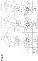
Fig. 5 is a diagram showing an operation of the vehicle door latch device ofFig. 1 , as seen at a cross-section taken along line 5-5 ofFig. 3 ; and -
Fig. 6 is a diagram showing an operation of a prior art vehicle door latch device. - Hereinafter, a preferred embodiment of the present invention will be described with reference to drawings.
- As shown in
Figs. 1 to 5 , a vehicle door latch device includes abody 11, which is, for example, made of resin, ametal base plate 12, and ametal sub-base plate 13. Thebase plate 12 and thesub-base plate 13 sandwich thebody 11 and form an accommodation space. Thebody 11, thebase plate 12, and thesub-base plate 13 are integrally assembled to form a housing attached to a vehicle door. To guide entry (relative entry) astriker 10 provided in the vehicle body (refer toFig. 1 ), thebody 11 has a guide portion 11 a having a channel-like cross section, and thebase plate 12 has arectangular guide hole 12a. - A
latch 14 is accommodated between thebody 11 and thebase plate 12. The distal end of asupport pin 15 is passed through thesub-base plate 13, thebody 11, thelatch 14, and thebase plate 12 in this order, and is retained by thebase plate 12. Thelatch 14 is supported to be rotatable about thesupport pin 15. Thelatch 14 is formed like scissors and has anengaging groove 14a, which is meshed with thestriker 10 by drawing in thestriker 10 when receiving thestriker 10. - A torsion coil spring (urging member) 16, which is arranged between the
body 11 and thelatch 14, has a coil portion, a first end, and a second end. The coil portion is arranged coaxially about thesupport pin 15, and the first and second ends are engaged with thelatch 14 and the body 11 (housing), respectively. Thetorsion coil spring 16 applies a predetermined force to thelatch 14 so as to limit rotation of thelatch 14. When thelatch 14 rotates, thelatch 14 is urged by the force and is rotated to return to the original position. Therefore, when thelatch 14 is released from the surrounding members, for example, when the vehicle door is open, thetorsion coil spring 16 always urges thelatch 14 to rotate such that the engaginggroove 14a faces the direction of entry of the striker 10 (seeFig. 5 ). At this time, thelatch 14 is held such that the opening of the engaginggroove 14a is oriented in the same direction as the openings of the guide portion 11a and theguide hole 12a. - A
pole 17 is provided between thebase plate 12 and thesub-base plate 13. Thepole 17 includes a block-likemain body portion 17a and ashaft portion 17b. Themain body portion 17a is accommodated between thebody 11 and thebase plate 12 and below thelatch 14, and theshaft portion 17b extends from a center of themain body portion 17a. The distal end of theshaft portion 17b is passed through thebody 11, thesub-base plate 13, and a center of alift lever 18 in this order, and is fitted and retained in the center of thelift lever 18. When operating force is transmitted to thelift lever 18, for example, from the door handle of the vehicle door through an unillustrated actuation mechanism, thelift lever 18 rotates integrally with thepole 17. - The
shaft portion 17b is passed through thebase plate 12, so that thepole 17 is rotatably supported by the base plate 12 (housing). In this manner, thepole 17, which is rotatably supported by the housing, engages thelatch 14 with themain body portion 17a, thereby restricting rotation of thelatch 14. Rotation of thelatch 14 is restricted when thelatch 14 is meshed with thestriker 10, for example, when the vehicle door is closed. When the restriction of the rotation by thepole 17 is cancelled, thelatch 14, which is meshed with thestriker 10, is urged by thetorsion coil spring 16 and is rotated to return to a position where the engaginggroove 14a faces in the direction of entry of thestriker 10, that is, to a position where thestriker 10 can exit the engaginggroove 14a. - As shown in
Fig. 4 , thebase plate 12 has a circularshaft receiving hole 12b, which serves as a support hole. Theshaft portion 17b of thepole 17 is rotatably supported by theshaft receiving hole 12b (the base plate 12) so that its outer circumferential surface slides on the inner circumferential surface of theshaft receiving hole 12b. A clearance C (refer toFig. 5 ) exists between the outer circumferential surface of theshaft portion 17b and the inner circumferential surface of theshaft receiving hole 12b. The clearance C allows theshaft portion 17b to rotate relative to theshaft receiving hole 12b. In addition to this, a similar shaft receiving hole may be formed in thesub-base plate 13. - A
helical torsion spring 19, which is a torsion coil spring, is located between thebody 11 and thesub-base plate 13. Thehelical torsion spring 19 includes a helical portion (coil portion) 19a, through which theshaft portion 17b of thepole 17 is passed. Thehelical portion 19a is located in a space formed between thebody 11 and thesub-base plate 13 and below the guide portion 11 a. - The
helical torsion spring 19 includes a firstengaging leg 19b and a secondengaging leg 19c. The firstengaging leg 19b extends radially outward in relation to thehelical portion 19a to be passed through thebody 11 and engaged with themain body portion 17a. The secondengaging leg 19c also extends radially outward in relation to thehelical portion 19a to be engaged with an engagingportion 13a of thesub-base plate 13. The first and secondengaging legs helical portion 19a. As shown inFig. 5 , thehelical torsion spring 19 always urges themain body portion 17a to rotate in the counterclockwise direction as viewed in the drawing, or in a direction to engage with thelatch 14, so that themain body portion 17a is engaged with astopper 20 provided on thebody 11. Thepole 17 can be engaged with thelatch 14 by causing themain body portion 17a to contact thelatch 14 meshed with thestriker 10. - As shown in
Figs. 4 and5 , thebody 11 has a projectingwall 21 located below thehelical portion 19a to be pressed against the outer circumferential surface of thehelical portion 19a. The projectingwall 21 projects in a direction opposite to thebase plate 12. The projectingwall 21 extends substantially parallel with theshaft portion 17b. When thehelical portion 19a is twisted and its diameter is reduced, an urging force is applied to thepole 17 through the firstengaging leg 19b. In this state, the projectingwall 21 receives an urging force that acts on thehelical portion 19a as a reactive force against the force applied to thepole 17. - The operation of the vehicle door latch device will now be described.
- As shown in
Fig. 5 , when a vehicle door is in an openable state (hereinafter, referred to as "initial state") and thestriker 10 is not meshed with thelatch 14, themain body portion 17a of thepole 17 contacts thestopper 20 at a location marked by sign o. At this time, themain body portion 17a receives, through the firstengaging leg 19b of thehelical torsion spring 19, a force (indicated by thick arrows) that rotates thepole 17 counterclockwise as viewed in the drawings about a portion that contacts thestopper 20 as a fulcrum. The urging force urges theshaft portion 17b of thepole 17 toward thelatch 14, thereby causing theshaft portion 17b to contact the inner circumferential surface of theshaft receiving hole 12b. At this time, the projectingwall 21 receives an urging force (indicated by thin arrows), which is a reactive force against the above described urging force, through thehelical portion 19a. That is, theshaft portion 17b of thepole 17 does not receive any urging force through thehelical portion 19a. Therefore, as shown in the left lower part ofFig. 5 in an exaggerated manner, thepole 17 is arranged at an eccentric position in theshaft receiving hole 12b such that the clearance C between theshaft portion 17b and the inner circumferential surface of theshaft receiving hole 12b is zero at the top, and the clearance C is greater at the bottom. - When the vehicle door is manipulated to be closed, rotation of the
latch 14 accompanying the entry of thestriker 10 presses thepole 17 against thelatch 14, so that thepole 17 is rotated clockwise while acting against the urging force of thehelical torsion spring 19. The part of thepole 17 that contacts thelatch 14 is indicated by the sign o. At this time, themain body portion 17a of thepole 17 is pressed downward by thelatch 14 at the contact position. At this time, although the urging force acting on the projectingwall 21 through thehelical portion 19a (indicated by thin arrows in the drawing) is greater than that in the initial state, theshaft portion 17b of thepole 17 naturally receives no urging force through thehelical portion 19a. Thus, even though theshaft portion 17b is slightly moved within theshaft receiving hole 12b, thepole 17 is at such a position in theshaft receiving hole 12b that the clearance C between theshaft portion 17b and the inner circumferential surface of theshaft receiving hole 12b is still zero at the top and is greater than zero at the bottom. That is, when thepole 17 is being rotated against the urging force of thehelical torsion spring 19, the projectingwall 21 is held in contact with the outer circumferential of thehelical portion 19a. In this manner, the projectingwall 21 maintains the contacting state of the outer circumferential surface of theshaft portion 17b and the inner circumferential surface of theshaft receiving hole 12b and the state of the clearance C substantially to the same as the initial state. That is, at a side opposite to the contacting parts of the projectingwall 21 and thehelical portion 19a with respect to theshaft portion 17b, the projectingwall 21 maintains a state where the outer circumferential surface of theshaft portion 17b and the inner circumferential surface of theshaft receiving hole 12b contact each other. - Then, the
pole 17 is released from thelatch 14 again immediately after thelatch 14 draws in thestriker 10 halfway, and thelatch 14 is in a half-meshed state, thepole 17 returns to the initial state. At this time, even though theshaft portion 17b is slightly moved within theshaft receiving hole 12b, thepole 17 is at such a position in theshaft receiving hole 12b that the clearance C between theshaft portion 17b and the inner circumferential surface of theshaft receiving hole 12b is still zero at the top and is greater than zero at the bottom. - Thereafter, the
latch 14 is urged by thetorsion coil spring 16 and acts to rotate to return to the original position. When returned to the initial state, thepole 17 causes thelatch 14 to engage with themain body portion 17a, so that the rotation of thelatch 14 is restricted and thelatch 14 is in the half-meshed state with thestriker 10. The vehicle door is thus maintained half-closed. - That is, in the present embodiment, the movement of the
shaft portion 17b within theshaft receiving hole 12b when the vehicle door is manipulated to be closed, that is, changes in the clearance C is small. Therefore, theshaft portion 17b, which moves within theshaft receiving hole 12b, is prevented from hitting the inner circumferential surface of theshaft receiving hole 12b. Unnatural hammering noise is thus reduced. - When the vehicle door is further manipulated from the half-closed state to the fully-closed state, operation similar to the above described operation prevents unnatural hammering noise from being produced.
- For example, if operating force is transmitted to the
lift lever 18 from the door handle as describe above when the vehicle door is in the fully-closed state, thelift lever 18 rotates integrally with thepole 17, thereby cancelling the restriction of the rotation of thelatch 14 by thepole 17. Accordingly, thelatch 14, which is meshed with thestriker 10, is urged by thetorsion coil spring 16 and is rotated to return to a position where the engaginggroove 14a faces in the direction of entry of thestriker 10, that is, to a position where thestriker 10 can exit the engaginggroove 14a. The vehicle door is then in the openable state. - The above illustrated embodiment has the following advantages.
- (1) In the present embodiment, the body 11 (housing) has the projecting
wall 21. When the firstengaging leg 19b applies an urging force to thepole 17, the projectingwall 21 contacts the outer circumferential surface of thehelical portion 19a and receives an urging force that acts on thehelical portion 19a as a reactive force against the urging force applied to thepole 17. Therefore, in a case where the vehicle door is manipulated to be closed, when thepole 17 is rotated against the urging force of thehelical torsion spring 19 by rotation of thelatch 14 accompanying the entry of thestriker 10 into the engaginggroove 14a, the above described urging force acting on thehelical portion 19a is received by the projectingwall 21. Therefore, theshaft portion 17b is prevented from moving within theshaft receiving hole 12b, and from hitting the inner circumferential surface of theshaft receiving hole 12b and producing unnatural hammering noise. Accordingly, the user is prevented from being disturbed by hammering noise.
Thehelical portion 19a is located inside the projectingwall 21 with respect to the radial direction of theshaft portion 17b. Therefore, the size of thehelical torsion spring 19 can be reduced, and the size of the entire device can be reduced. - (2) In the present embodiment, the projecting
wall 21, which contacts the outer circumferential wall of thehelical portion 19a, is formed at a part of the lower potion of theshaft receiving hole 12b. Thus, when thepole 17 is rotated, sliding resistance between thehelical portion 19a and the projectingwall 21 is minimized, which prevents the required operating force from being unnecessarily increased. - (3) In the present embodiment, the helical torsion spring 19 (the
helical portion 19a) is arranged about theshaft portion 17b of thepole 17 to be coaxial with theshaft portion 17b. Thus, linear loading characteristics are obtained. This improves the operating feel of rotation of the pole 17 (manipulation of the door handle), and the reliability of the operation of thepole 17 is improved. - The above described embodiments may be modified as follows.
- In the above embodiment, the projecting
wall 21, which contacts the outer circumferential wall of thehelical portion 19a, is located at a part of the lower portion of theshaft receiving hole 12b. However, the projectingwall 21 may be formed to cylindrically project so as to encompass theshaft receiving hole 12b. - In the above embodiment, as long as the clearance is maintained to a constant size between the outer circumferential surface of the
shaft portion 17b and the inner circumferential surface of theshaft receiving hole 12b, the projectingwall 21 may be formed to contact any part of thehelical portion 19a in any manner.
Claims (5)
- A vehicle door latch (14) device, comprising:a housing (11, 12, 13) structured to be provided in a vehicle door;a latch (14) rotatably supported by the housing (11, 12, 13), wherein a striker (10) provided in the vehicle body can be fitted to the latch (14);a pole (17) having a shaft portion (17b) rotatably supported by the housing (11, 12, 14), wherein the pole (17) is engageable with the latch (14) to restrict rotation of the latch (14);a helical torsion spring (19) having a helical portion (19a) through which the shaft portion (17b) is passed, a first engaging leg (19b) extending radially outward in relation to the helical portion (19a), and a second engaging leg (19c) extending radially outward in relation to the helical portion (19a), wherein the first engaging leg (19b) is engaged with the pole (17), and the second engaging leg (19c) is engaged with the housing (11, 12, 13), the helical torsion spring (19) always urging the pole (17) to rotate to an engagement position where the pole (17) can be engaged with the latch (14); anda projecting wall (21) formed in the housing (11, 12, 13), the projecting wall (21) contacting an outer circumferential surface of the helical portion (19a),wherein the housing (11, 12, 13) has a support hole (12b) having an inner circumferential surface that slides on an outer circumferential surface of the shaft portion (17b),wherein a clearance (C) is provided between the outer circumferential surface of the shaft portion (17b) and the inner circumferential surface of the support hole (12b), the clearance (C) allowing the shaft portion (17b) to rotate relative to the support hole (12b), andwherein, at a position opposite to the contacting part of the projecting wall (21) and the helical portion (19a) with respect to the shaft portion (17b), the projecting wall (21) maintains a state where the outer circumferential surface of the shaft portion (17b) contacts the inner circumferential surface of the support hole (12b).
- The vehicle door latch device according to claim 1, wherein the first and second engaging legs (19b, 19c) extend in directions opposite to each other.
- The vehicle door latch device according to claim 1 or 2, wherein, when the diameter of the helical portion is reduced so that the helical portion (19a) applies an urging force to the pole (17) through the first engaging leg (19b), the projecting wall (21) receives an urging force that acts of the helical portion as a reactive force against the force applied to the pole.
- The vehicle door latch device according to any of the claims 1 to 3, wherein the housing (11, 12, 13) includes a body (11) and a base plate (12, 13), which are assembled to each other to form an accommodation space for accommodating the latch (14) and the pole (17),
wherein the support hole is formed in the base plate, and the shaft portion (17b) extending through the body, and
wherein the projecting wall (21) extends from the body in a direction opposite to the base plate and substantially parallel with the shaft portion. - The vehicle door latch device according to any one of claims 1 to 4, wherein the latch (14) has an engaging groove (14a) that can be meshed with the striker (10),
wherein an urging member is provided that always urges the latch to rotate, thereby orienting the engaging groove in a direction of entry of the striker,
wherein, when the vehicle door is manipulated to be closed, the latch is rotated as the striker enters the engaging groove, and the latch presses the pole (17), so that the pole is rotated against the urging force of the helical torsion spring (19), and
wherein, after the striker is meshed with the engaging groove, the pole is released from the pressing by the latch and is rotated by the urging force of the helical torsion spring to return to the engagement position, so that rotation of the latch is restricted in a state where the striker is meshed with the engaging groove.
Applications Claiming Priority (2)
| Application Number | Priority Date | Filing Date | Title |
|---|---|---|---|
| JP2007263188A JP4935612B2 (en) | 2007-10-09 | 2007-10-09 | Vehicle door latch device |
| PCT/JP2008/067650 WO2009047996A1 (en) | 2007-10-09 | 2008-09-29 | Vehicle door latch device |
Publications (3)
| Publication Number | Publication Date |
|---|---|
| EP2196606A1 EP2196606A1 (en) | 2010-06-16 |
| EP2196606A4 EP2196606A4 (en) | 2014-06-11 |
| EP2196606B1 true EP2196606B1 (en) | 2017-05-24 |
Family
ID=40549141
Family Applications (1)
| Application Number | Title | Priority Date | Filing Date |
|---|---|---|---|
| EP08837565.4A Not-in-force EP2196606B1 (en) | 2007-10-09 | 2008-09-29 | Vehicle door latch device |
Country Status (5)
| Country | Link |
|---|---|
| US (1) | US8376419B2 (en) |
| EP (1) | EP2196606B1 (en) |
| JP (1) | JP4935612B2 (en) |
| CN (1) | CN102131993B (en) |
| WO (1) | WO2009047996A1 (en) |
Families Citing this family (15)
| Publication number | Priority date | Publication date | Assignee | Title |
|---|---|---|---|---|
| GB2480490B (en) * | 2010-05-21 | 2016-06-08 | Inteva Products Usa Llc | Latch assembly |
| DE102010063868A1 (en) * | 2010-12-22 | 2012-06-28 | Kiekert Ag | Reinforced motor vehicle lock |
| JP5923789B2 (en) | 2012-04-05 | 2016-05-25 | 三井金属アクト株式会社 | Actuator unit |
| JP5995591B2 (en) * | 2012-07-31 | 2016-09-21 | アイシン機工株式会社 | Door lock device |
| JP5534283B1 (en) * | 2012-09-07 | 2014-06-25 | 三井金属アクト株式会社 | Door latch device for automobile |
| DE202012103608U1 (en) * | 2012-09-20 | 2012-10-24 | Kiekert Aktiengesellschaft | Motor vehicle door lock |
| DE102012023236A1 (en) * | 2012-11-28 | 2014-05-28 | Kiekert Aktiengesellschaft | Motor vehicle door lock |
| FR2999636B1 (en) * | 2012-12-19 | 2017-12-01 | Lisi Aerospace | LOCK FOR AIRCRAFT |
| JP5681223B2 (en) * | 2013-03-07 | 2015-03-04 | シロキ工業株式会社 | Locking device |
| JP6326673B2 (en) * | 2013-12-27 | 2018-05-23 | 三井金属アクト株式会社 | Vehicle door latch device |
| JP6782285B2 (en) * | 2018-08-07 | 2020-11-11 | 三井金属アクト株式会社 | Automotive door latch device |
| JP7288381B2 (en) * | 2019-10-04 | 2023-06-07 | 株式会社城南製作所 | Vehicle hood lock device and method for manufacturing vehicle hood lock device |
| JP7288382B2 (en) * | 2019-10-04 | 2023-06-07 | 株式会社城南製作所 | Vehicle hood lock device and method for manufacturing vehicle hood lock device |
| JP6915013B2 (en) * | 2019-10-04 | 2021-08-04 | 株式会社城南製作所 | Vehicle hood lock device |
| DE102019131176A1 (en) * | 2019-11-19 | 2021-05-20 | Kiekert Aktiengesellschaft | Motor vehicle lock, in particular motor vehicle door lock |
Family Cites Families (19)
| Publication number | Priority date | Publication date | Assignee | Title |
|---|---|---|---|---|
| US3504511A (en) * | 1968-03-04 | 1970-04-07 | Perry E Allen | Electric lock release |
| FR2372299B1 (en) * | 1976-11-30 | 1979-03-23 | Cerdan Jacques | |
| US4334704A (en) * | 1980-03-31 | 1982-06-15 | Mitsui Kinzoku Kogyo Kabushiki Kaisha | Automobile door locking mechanism |
| US4653784A (en) * | 1986-05-27 | 1987-03-31 | Lee Raymond J | Spring-loaded oscillating cam latch |
| JPS6346566A (en) * | 1986-08-14 | 1988-02-27 | Canon Inc | Character processor |
| JPS6346566U (en) * | 1986-09-16 | 1988-03-29 | ||
| DE3903274A1 (en) * | 1988-02-03 | 1989-08-17 | Magna Int Inc | LOCKING MECHANISM, ESPECIALLY FOR THE BONNET OF A MOTOR VEHICLE |
| JP2516432B2 (en) * | 1989-07-24 | 1996-07-24 | 株式会社大井製作所 | Door lock device for automobile |
| US5048879A (en) | 1989-12-27 | 1991-09-17 | Aisin Seiki Kabushiki Kaisha | Door lock for an automobile |
| JP2519638Y2 (en) | 1989-12-27 | 1996-12-11 | アイシン精機株式会社 | Housing for door lock device |
| JP4538939B2 (en) | 2000-10-26 | 2010-09-08 | アイシン精機株式会社 | Door lock device for automobile |
| JP3939097B2 (en) * | 2001-01-24 | 2007-06-27 | 株式会社大井製作所 | Automotive locking device |
| US6547291B1 (en) * | 2001-01-26 | 2003-04-15 | Midway Products Group, Inc. | Latch assembly for vehicle hood |
| JP4142325B2 (en) * | 2002-04-04 | 2008-09-03 | シロキ工業株式会社 | Locking device |
| FR2852993B1 (en) * | 2003-03-27 | 2005-05-06 | Valeo Securite Habitacle | LOCK FOR OPENING OF A MOTOR VEHICLE, DECORATIVE / CONDEMNATION MEMORIZATION |
| KR20050032210A (en) * | 2003-10-01 | 2005-04-07 | 기아자동차주식회사 | Door latch structure for a vehicle |
| JP4239785B2 (en) | 2003-10-21 | 2009-03-18 | 三菱自動車工業株式会社 | Vehicle door member opener device |
| GB0703597D0 (en) * | 2007-02-23 | 2007-04-04 | Meritor Technology Inc | Latch assembley |
| US8235428B2 (en) * | 2009-07-14 | 2012-08-07 | Kiekert Ag | Lock unit having a slotted pawl |
-
2007
- 2007-10-09 JP JP2007263188A patent/JP4935612B2/en not_active Expired - Fee Related
-
2008
- 2008-09-29 CN CN2008801012282A patent/CN102131993B/en not_active Expired - Fee Related
- 2008-09-29 WO PCT/JP2008/067650 patent/WO2009047996A1/en active Application Filing
- 2008-09-29 EP EP08837565.4A patent/EP2196606B1/en not_active Not-in-force
- 2008-09-29 US US12/670,074 patent/US8376419B2/en active Active
Non-Patent Citations (1)
| Title |
|---|
| None * |
Also Published As
| Publication number | Publication date |
|---|---|
| JP2009091804A (en) | 2009-04-30 |
| US20100194121A1 (en) | 2010-08-05 |
| JP4935612B2 (en) | 2012-05-23 |
| WO2009047996A1 (en) | 2009-04-16 |
| EP2196606A1 (en) | 2010-06-16 |
| EP2196606A4 (en) | 2014-06-11 |
| CN102131993A (en) | 2011-07-20 |
| CN102131993B (en) | 2013-07-03 |
| US8376419B2 (en) | 2013-02-19 |
Similar Documents
| Publication | Publication Date | Title |
|---|---|---|
| EP2196606B1 (en) | Vehicle door latch device | |
| JP4845519B2 (en) | Door lock device and method of assembling door lock device | |
| US6619744B2 (en) | Vehicle seat fitted with a hinge mechanism | |
| US7559586B2 (en) | Door lock apparatus for a vehicle | |
| US7874599B2 (en) | Door lock apparatus for vehicles | |
| JP5571383B2 (en) | Rotating claw latch | |
| JP6232612B2 (en) | Door latch device for automobile | |
| US20100090480A1 (en) | Striker assembly for vehicle | |
| JP2005188242A (en) | Lock device | |
| JP4928791B2 (en) | Door lock device | |
| JP5909056B2 (en) | Shift lever unit | |
| JP5014082B2 (en) | Vehicle door latch device | |
| JP3314023B2 (en) | Vehicle door lock device | |
| US6918275B2 (en) | Manual internal release assembly for a vehicle decklid latch | |
| EP4317638A1 (en) | Vehicle door handle device | |
| JP2007197974A (en) | Door locking device | |
| JP2019112805A (en) | Sliding door lock | |
| JP5020851B2 (en) | Opening and closing device for door of vehicle storage device | |
| JP5453133B2 (en) | Opening / closing mechanism of opening / closing member, container | |
| JP4712079B2 (en) | Switchgear | |
| US7192016B2 (en) | Torsion spring assembling structure | |
| JP3330550B2 (en) | Car door outside handle device | |
| JP3660320B2 (en) | Shift lever device | |
| JP3314022B2 (en) | Vehicle door lock device | |
| JP2002220961A (en) | Transmission mechanism of latch device and latch device |
Legal Events
| Date | Code | Title | Description |
|---|---|---|---|
| PUAI | Public reference made under article 153(3) epc to a published international application that has entered the european phase |
Free format text: ORIGINAL CODE: 0009012 |
|
| 17P | Request for examination filed |
Effective date: 20100226 |
|
| AK | Designated contracting states |
Kind code of ref document: A1 Designated state(s): AT BE BG CH CY CZ DE DK EE ES FI FR GB GR HR HU IE IS IT LI LT LU LV MC MT NL NO PL PT RO SE SI SK TR |
|
| AX | Request for extension of the european patent |
Extension state: AL BA MK RS |
|
| DAX | Request for extension of the european patent (deleted) | ||
| A4 | Supplementary search report drawn up and despatched |
Effective date: 20140514 |
|
| RIC1 | Information provided on ipc code assigned before grant |
Ipc: E05B 85/26 20140101ALI20140508BHEP Ipc: E05B 77/36 20140101AFI20140508BHEP Ipc: E05B 15/04 20060101ALN20140508BHEP Ipc: E05B 85/02 20140101ALN20140508BHEP |
|
| RIC1 | Information provided on ipc code assigned before grant |
Ipc: E05B 85/26 20140101ALI20161125BHEP Ipc: E05B 77/36 20140101AFI20161125BHEP Ipc: E05B 85/02 20140101ALN20161125BHEP Ipc: E05B 15/04 20060101ALN20161125BHEP |
|
| GRAP | Despatch of communication of intention to grant a patent |
Free format text: ORIGINAL CODE: EPIDOSNIGR1 |
|
| STAA | Information on the status of an ep patent application or granted ep patent |
Free format text: STATUS: GRANT OF PATENT IS INTENDED |
|
| RIC1 | Information provided on ipc code assigned before grant |
Ipc: E05B 85/02 20140101ALN20161216BHEP Ipc: E05B 15/04 20060101ALN20161216BHEP Ipc: E05B 77/36 20140101AFI20161216BHEP Ipc: E05B 85/26 20140101ALI20161216BHEP |
|
| INTG | Intention to grant announced |
Effective date: 20170118 |
|
| GRAS | Grant fee paid |
Free format text: ORIGINAL CODE: EPIDOSNIGR3 |
|
| GRAJ | Information related to disapproval of communication of intention to grant by the applicant or resumption of examination proceedings by the epo deleted |
Free format text: ORIGINAL CODE: EPIDOSDIGR1 |
|
| GRAL | Information related to payment of fee for publishing/printing deleted |
Free format text: ORIGINAL CODE: EPIDOSDIGR3 |
|
| STAA | Information on the status of an ep patent application or granted ep patent |
Free format text: STATUS: REQUEST FOR EXAMINATION WAS MADE |
|
| REG | Reference to a national code |
Ref country code: DE Ref legal event code: R079 Ref document number: 602008050415 Country of ref document: DE Free format text: PREVIOUS MAIN CLASS: E05B0065320000 Ipc: E05B0077360000 |
|
| GRAR | Information related to intention to grant a patent recorded |
Free format text: ORIGINAL CODE: EPIDOSNIGR71 |
|
| STAA | Information on the status of an ep patent application or granted ep patent |
Free format text: STATUS: GRANT OF PATENT IS INTENDED |
|
| GRAA | (expected) grant |
Free format text: ORIGINAL CODE: 0009210 |
|
| STAA | Information on the status of an ep patent application or granted ep patent |
Free format text: STATUS: THE PATENT HAS BEEN GRANTED |
|
| RIN1 | Information on inventor provided before grant (corrected) |
Inventor name: KONOMOTO, NORIO Inventor name: MURAMATSU, AKIRA Inventor name: TSUKAMOTO, KOSUKE |
|
| INTC | Intention to grant announced (deleted) | ||
| RIC1 | Information provided on ipc code assigned before grant |
Ipc: E05B 85/26 20140101ALI20170329BHEP Ipc: E05B 77/36 20140101AFI20170329BHEP Ipc: E05B 15/04 20060101ALN20170329BHEP Ipc: E05B 85/02 20140101ALN20170329BHEP |
|
| AK | Designated contracting states |
Kind code of ref document: B1 Designated state(s): AT BE BG CH CY CZ DE DK EE ES FI FR GB GR HR HU IE IS IT LI LT LU LV MC MT NL NO PL PT RO SE SI SK TR |
|
| INTG | Intention to grant announced |
Effective date: 20170419 |
|
| REG | Reference to a national code |
Ref country code: GB Ref legal event code: FG4D |
|
| REG | Reference to a national code |
Ref country code: CH Ref legal event code: EP |
|
| REG | Reference to a national code |
Ref country code: IE Ref legal event code: FG4D |
|
| REG | Reference to a national code |
Ref country code: AT Ref legal event code: REF Ref document number: 896103 Country of ref document: AT Kind code of ref document: T Effective date: 20170615 |
|
| REG | Reference to a national code |
Ref country code: DE Ref legal event code: R096 Ref document number: 602008050415 Country of ref document: DE |
|
| REG | Reference to a national code |
Ref country code: FR Ref legal event code: PLFP Year of fee payment: 10 |
|
| REG | Reference to a national code |
Ref country code: NL Ref legal event code: MP Effective date: 20170524 |
|
| REG | Reference to a national code |
Ref country code: LT Ref legal event code: MG4D |
|
| REG | Reference to a national code |
Ref country code: AT Ref legal event code: MK05 Ref document number: 896103 Country of ref document: AT Kind code of ref document: T Effective date: 20170524 |
|
| PG25 | Lapsed in a contracting state [announced via postgrant information from national office to epo] |
Ref country code: LT Free format text: LAPSE BECAUSE OF FAILURE TO SUBMIT A TRANSLATION OF THE DESCRIPTION OR TO PAY THE FEE WITHIN THE PRESCRIBED TIME-LIMIT Effective date: 20170524 Ref country code: ES Free format text: LAPSE BECAUSE OF FAILURE TO SUBMIT A TRANSLATION OF THE DESCRIPTION OR TO PAY THE FEE WITHIN THE PRESCRIBED TIME-LIMIT Effective date: 20170524 Ref country code: GR Free format text: LAPSE BECAUSE OF FAILURE TO SUBMIT A TRANSLATION OF THE DESCRIPTION OR TO PAY THE FEE WITHIN THE PRESCRIBED TIME-LIMIT Effective date: 20170825 Ref country code: NO Free format text: LAPSE BECAUSE OF FAILURE TO SUBMIT A TRANSLATION OF THE DESCRIPTION OR TO PAY THE FEE WITHIN THE PRESCRIBED TIME-LIMIT Effective date: 20170824 Ref country code: FI Free format text: LAPSE BECAUSE OF FAILURE TO SUBMIT A TRANSLATION OF THE DESCRIPTION OR TO PAY THE FEE WITHIN THE PRESCRIBED TIME-LIMIT Effective date: 20170524 Ref country code: AT Free format text: LAPSE BECAUSE OF FAILURE TO SUBMIT A TRANSLATION OF THE DESCRIPTION OR TO PAY THE FEE WITHIN THE PRESCRIBED TIME-LIMIT Effective date: 20170524 Ref country code: HR Free format text: LAPSE BECAUSE OF FAILURE TO SUBMIT A TRANSLATION OF THE DESCRIPTION OR TO PAY THE FEE WITHIN THE PRESCRIBED TIME-LIMIT Effective date: 20170524 |
|
| PG25 | Lapsed in a contracting state [announced via postgrant information from national office to epo] |
Ref country code: NL Free format text: LAPSE BECAUSE OF FAILURE TO SUBMIT A TRANSLATION OF THE DESCRIPTION OR TO PAY THE FEE WITHIN THE PRESCRIBED TIME-LIMIT Effective date: 20170524 Ref country code: IS Free format text: LAPSE BECAUSE OF FAILURE TO SUBMIT A TRANSLATION OF THE DESCRIPTION OR TO PAY THE FEE WITHIN THE PRESCRIBED TIME-LIMIT Effective date: 20170924 Ref country code: BG Free format text: LAPSE BECAUSE OF FAILURE TO SUBMIT A TRANSLATION OF THE DESCRIPTION OR TO PAY THE FEE WITHIN THE PRESCRIBED TIME-LIMIT Effective date: 20170824 Ref country code: SE Free format text: LAPSE BECAUSE OF FAILURE TO SUBMIT A TRANSLATION OF THE DESCRIPTION OR TO PAY THE FEE WITHIN THE PRESCRIBED TIME-LIMIT Effective date: 20170524 Ref country code: LV Free format text: LAPSE BECAUSE OF FAILURE TO SUBMIT A TRANSLATION OF THE DESCRIPTION OR TO PAY THE FEE WITHIN THE PRESCRIBED TIME-LIMIT Effective date: 20170524 |
|
| PG25 | Lapsed in a contracting state [announced via postgrant information from national office to epo] |
Ref country code: SK Free format text: LAPSE BECAUSE OF FAILURE TO SUBMIT A TRANSLATION OF THE DESCRIPTION OR TO PAY THE FEE WITHIN THE PRESCRIBED TIME-LIMIT Effective date: 20170524 Ref country code: CZ Free format text: LAPSE BECAUSE OF FAILURE TO SUBMIT A TRANSLATION OF THE DESCRIPTION OR TO PAY THE FEE WITHIN THE PRESCRIBED TIME-LIMIT Effective date: 20170524 Ref country code: EE Free format text: LAPSE BECAUSE OF FAILURE TO SUBMIT A TRANSLATION OF THE DESCRIPTION OR TO PAY THE FEE WITHIN THE PRESCRIBED TIME-LIMIT Effective date: 20170524 Ref country code: RO Free format text: LAPSE BECAUSE OF FAILURE TO SUBMIT A TRANSLATION OF THE DESCRIPTION OR TO PAY THE FEE WITHIN THE PRESCRIBED TIME-LIMIT Effective date: 20170524 Ref country code: DK Free format text: LAPSE BECAUSE OF FAILURE TO SUBMIT A TRANSLATION OF THE DESCRIPTION OR TO PAY THE FEE WITHIN THE PRESCRIBED TIME-LIMIT Effective date: 20170524 |
|
| REG | Reference to a national code |
Ref country code: DE Ref legal event code: R097 Ref document number: 602008050415 Country of ref document: DE |
|
| PG25 | Lapsed in a contracting state [announced via postgrant information from national office to epo] |
Ref country code: PL Free format text: LAPSE BECAUSE OF FAILURE TO SUBMIT A TRANSLATION OF THE DESCRIPTION OR TO PAY THE FEE WITHIN THE PRESCRIBED TIME-LIMIT Effective date: 20170524 Ref country code: IT Free format text: LAPSE BECAUSE OF FAILURE TO SUBMIT A TRANSLATION OF THE DESCRIPTION OR TO PAY THE FEE WITHIN THE PRESCRIBED TIME-LIMIT Effective date: 20170524 |
|
| PLBE | No opposition filed within time limit |
Free format text: ORIGINAL CODE: 0009261 |
|
| STAA | Information on the status of an ep patent application or granted ep patent |
Free format text: STATUS: NO OPPOSITION FILED WITHIN TIME LIMIT |
|
| REG | Reference to a national code |
Ref country code: CH Ref legal event code: PL |
|
| 26N | No opposition filed |
Effective date: 20180227 |
|
| GBPC | Gb: european patent ceased through non-payment of renewal fee |
Effective date: 20170929 |
|
| PG25 | Lapsed in a contracting state [announced via postgrant information from national office to epo] |
Ref country code: MC Free format text: LAPSE BECAUSE OF FAILURE TO SUBMIT A TRANSLATION OF THE DESCRIPTION OR TO PAY THE FEE WITHIN THE PRESCRIBED TIME-LIMIT Effective date: 20170524 Ref country code: SI Free format text: LAPSE BECAUSE OF FAILURE TO SUBMIT A TRANSLATION OF THE DESCRIPTION OR TO PAY THE FEE WITHIN THE PRESCRIBED TIME-LIMIT Effective date: 20170524 |
|
| REG | Reference to a national code |
Ref country code: IE Ref legal event code: MM4A |
|
| REG | Reference to a national code |
Ref country code: BE Ref legal event code: MM Effective date: 20170930 |
|
| PG25 | Lapsed in a contracting state [announced via postgrant information from national office to epo] |
Ref country code: LU Free format text: LAPSE BECAUSE OF NON-PAYMENT OF DUE FEES Effective date: 20170929 |
|
| PG25 | Lapsed in a contracting state [announced via postgrant information from national office to epo] |
Ref country code: CH Free format text: LAPSE BECAUSE OF NON-PAYMENT OF DUE FEES Effective date: 20170930 Ref country code: GB Free format text: LAPSE BECAUSE OF NON-PAYMENT OF DUE FEES Effective date: 20170929 Ref country code: LI Free format text: LAPSE BECAUSE OF NON-PAYMENT OF DUE FEES Effective date: 20170930 Ref country code: IE Free format text: LAPSE BECAUSE OF NON-PAYMENT OF DUE FEES Effective date: 20170929 |
|
| REG | Reference to a national code |
Ref country code: FR Ref legal event code: PLFP Year of fee payment: 11 |
|
| PG25 | Lapsed in a contracting state [announced via postgrant information from national office to epo] |
Ref country code: BE Free format text: LAPSE BECAUSE OF NON-PAYMENT OF DUE FEES Effective date: 20170930 |
|
| PG25 | Lapsed in a contracting state [announced via postgrant information from national office to epo] |
Ref country code: MT Free format text: LAPSE BECAUSE OF NON-PAYMENT OF DUE FEES Effective date: 20170929 |
|
| PG25 | Lapsed in a contracting state [announced via postgrant information from national office to epo] |
Ref country code: HU Free format text: LAPSE BECAUSE OF FAILURE TO SUBMIT A TRANSLATION OF THE DESCRIPTION OR TO PAY THE FEE WITHIN THE PRESCRIBED TIME-LIMIT; INVALID AB INITIO Effective date: 20080929 |
|
| PG25 | Lapsed in a contracting state [announced via postgrant information from national office to epo] |
Ref country code: CY Free format text: LAPSE BECAUSE OF NON-PAYMENT OF DUE FEES Effective date: 20170524 |
|
| PGFP | Annual fee paid to national office [announced via postgrant information from national office to epo] |
Ref country code: DE Payment date: 20190917 Year of fee payment: 12 |
|
| PG25 | Lapsed in a contracting state [announced via postgrant information from national office to epo] |
Ref country code: TR Free format text: LAPSE BECAUSE OF FAILURE TO SUBMIT A TRANSLATION OF THE DESCRIPTION OR TO PAY THE FEE WITHIN THE PRESCRIBED TIME-LIMIT Effective date: 20170524 |
|
| PG25 | Lapsed in a contracting state [announced via postgrant information from national office to epo] |
Ref country code: PT Free format text: LAPSE BECAUSE OF FAILURE TO SUBMIT A TRANSLATION OF THE DESCRIPTION OR TO PAY THE FEE WITHIN THE PRESCRIBED TIME-LIMIT Effective date: 20170524 |
|
| PGFP | Annual fee paid to national office [announced via postgrant information from national office to epo] |
Ref country code: FR Payment date: 20200812 Year of fee payment: 13 |
|
| REG | Reference to a national code |
Ref country code: DE Ref legal event code: R119 Ref document number: 602008050415 Country of ref document: DE |
|
| PG25 | Lapsed in a contracting state [announced via postgrant information from national office to epo] |
Ref country code: DE Free format text: LAPSE BECAUSE OF NON-PAYMENT OF DUE FEES Effective date: 20210401 |
|
| PG25 | Lapsed in a contracting state [announced via postgrant information from national office to epo] |
Ref country code: FR Free format text: LAPSE BECAUSE OF NON-PAYMENT OF DUE FEES Effective date: 20210930 |