EP2196597B1 - Stützsäulen für überhöhte Böden und Herstellungsverfahren - Google Patents
Stützsäulen für überhöhte Böden und Herstellungsverfahren Download PDFInfo
- Publication number
- EP2196597B1 EP2196597B1 EP09176830A EP09176830A EP2196597B1 EP 2196597 B1 EP2196597 B1 EP 2196597B1 EP 09176830 A EP09176830 A EP 09176830A EP 09176830 A EP09176830 A EP 09176830A EP 2196597 B1 EP2196597 B1 EP 2196597B1
- Authority
- EP
- European Patent Office
- Prior art keywords
- column
- strip
- piece
- jamb
- seaming
- Prior art date
- Legal status (The legal status is an assumption and is not a legal conclusion. Google has not performed a legal analysis and makes no representation as to the accuracy of the status listed.)
- Active
Links
Images


Classifications
-
- E—FIXED CONSTRUCTIONS
- E04—BUILDING
- E04F—FINISHING WORK ON BUILDINGS, e.g. STAIRS, FLOORS
- E04F15/00—Flooring
- E04F15/02—Flooring or floor layers composed of a number of similar elements
- E04F15/024—Sectional false floors, e.g. computer floors
- E04F15/02447—Supporting structures
- E04F15/02464—Height adjustable elements for supporting the panels or a panel-supporting framework
- E04F15/0247—Screw jacks
Definitions
- the present invention relates to some innovative improvements applied to a supporting column for modular superelevated floors and the relative production process.
- Modular superelevated floors comprise a series of columns adjustable in height on which the panels are rested directly, or on which a framework structure which supports the panels is rested.
- the supporting columns In addition to be finely adjustable in height, in order to obtain an optimum leveling of the superelevated floor regardless of the quality of the bottom, the supporting columns must satisfy other requisites.
- the structure of the column must be capable of supporting the loads, even high, consisting of the panels, but above all what is resting on the floor.
- Floors are also subjected to vibratory stress which tends, for example, to loosen the height regulation means.
- the column must be composed of a small number of components which are easy to assemble and have a reduced cost.
- This column is provided by a screw which can be inserted into a tubular jamb.
- a general objective of the present invention is to overcome the drawbacks of the known art, with particular reference to the production of a supporting column for modular superelevated floors having a perfected characteristic guiding system of the tie-rod in the tube.
- a further objective of the invention is to provide a column produced so as to allow a reduction in the components in storage, at the same time allowing an almost immediate dispatch of the orders received from clients with lengths varying from millimeter to millimeter also without the necessity of subsequent treatment.
- Another objective is to produce a column, object of the present invention, in an extremely simple, economical and particularly functional manner, if compared to columns of the known type, also reducing the processing phases.
- a supporting column for modular superelevated floors has been conceived, together with a production process of said column, having the characteristics specified in the enclosed main claim and subclaims.
- a supporting column for modular superelevated floors in question is indicated as a whole with 10, and in the example illustrated, according to the present invention, comprises a lower resting base 11 and a top supporting element 12 destined for receiving floor panels (not shown), or a framework structure (also not shown), on which said panels are rested.
- the element 12 comprises a supporting plate or flange 13 (suitably shaped) and a shank or threaded tie-rod 14, stably and inseparably integral with each other as better described in patent Nr. 1340094 .
- the supporting plate 13 can have generic forms and dimensions, it can consist, for example, of a flat metallic sheet or a series of radial spokes.
- the drawings show a non-limiting embodiment of the plate 13, equipped with a series of holes 15 and deep-drawn grooves 16 suitable for allowing a versatile coupling with the floor panels, or with the supporting framework, and anti-noise, antistatic or conductive washers (not shown).
- the supporting plate 13 has a collar or sleeve 17 to which the above tie-rod 14 is firmly fixed in any of the known ways.
- the shank or tie-rod 14 can be threaded for its whole length and is obtained, for example, as a piece from a threaded bar, cut into the desired size to produce columns 10 of differing heights.
- the top support 12 (in the form of the plate 13) is constrained to the resting base 11 by threaded coupling means, so that the height of the column 10 can be accurately regulated.
- the resting base 11 comprises a lower plate 18 for resting on the ground and a hollow tubular body or jamb 19, firmly constrained at its lower end to the plate 18 (as explained hereunder), and equipped at the upper free end with a guiding bush 20 of the tie-rod 14.
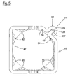
- the tubular jamb 19 has a polygonal transversal section, preferably but not necessarily substantially square, joined at the corners.
- said jamb 19 consists of at least one piece 24 of a strip of sheet, bent so as to bring the two free longitudinal edges 25, 26 of the strip 24 in correspondence with each other, said two edges 25, 26 being rigidly interconnected by means of a seaming 27 ( figure 5 ).
- Said seaming 27 substantially relates to the whole height of the jamb 19, and comprises a toothed section 28 on an edge of the strip 24 and a hooking section 29 on the other edge, said hooking section 29 being hooked onto said toothed section 28.
- the guiding bush 20 of the tie-rod 14 is made of a plastic material, it has a perimetric section 31, with a substantially polygonal plane, corresponding to the internal plane of the jamb 19, and a circular internal section 32 substantially corresponding to the diameter of the tie-rod 14 that it guides.
- said bush 20 is formed with a cut edge in order to define a flat external surface 33, which exactly fits the internal area 34 in correspondence with the seaming 27, whereas the other three surfaces have cavities 35, which are forcedly coupled with the deep-drawn ribbings 30 extending internally from the column 19.
- the bush 20 can be absent and the threaded tie-rod 14 can be suitably guided by the same ribbings 30, protruding internally from the tubular column 19.
- the ribbings 30' in correspondence with the base of the tubular column 19, also have the purpose of enabling the insertion and forced blockage of the same column on a central cylindrical shank 36 extending vertically from the lower resting base 11.
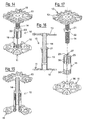
- tubular column 19 instead of being produced in a single piece of sheet plate 25, as shown in figures 18, 19, 20 , can be produced starting from two pieces 37, 38.
- the column according to the invention can be advantageously produced with the process schematized in figures 18-20 , starting from a piece 24 cut from a strip of sheet.
- the piece 24 is first deep-drawn into 30, 30', then shaped on the edges so as to define the sections 28, 29, bent into tubular form with a polygonal section, and finally the sections 28, 29 are joined together by means of seaming 27.
- the coupling between the two pieces 37, 38 is effected by hooking and seaming the hook sections 29 onto the toothed sections 28, as shown in figure 21 .
Landscapes
- Engineering & Computer Science (AREA)
- Architecture (AREA)
- General Engineering & Computer Science (AREA)
- Civil Engineering (AREA)
- Structural Engineering (AREA)
- Rod-Shaped Construction Members (AREA)
- Stringed Musical Instruments (AREA)
- Floor Finish (AREA)
Claims (8)
- Stützsäule für überhöhte Böden, umfassend eine Stützbasis (12), ein oberseitiges Stützelement (13) und Gewindekopplungselemente (14, 21) zum Regulieren der Höhe der Säule (10), wobei die Säule einen röhrenförmigen Pfosten (19) mit einem kantigen Querprofil aufweist, wobei der Pfosten (19) aus zumindest einem Teil eines Streifens aus gebogenem Blech (24) besteht, um dadurch die zwei freien Längsränder (25, 26) des Streifens (24) zu halten, die einander entsprechen, wobei die zwei Ränder (25, 26) mittels einer Falzung (27) starr verbunden sind,
dadurch gekennzeichnet, dass das Teil des Blechstreifens (25) kalibrierte Führungsrippen (30, 31') zum Verringern der Kopplungsabstände aufweist, wobei die Zwischenräume kleiner als diejenigen sind, die für das Rohr typisch sind;
wobei eine Führungshülse (20) einer Gewindezugstange (14), auf die eine Mutter (21) geschraubt ist, die an der Oberseite des Pfostens (19) gehalten ist, durch Einhaken in die Rippen (30, 31') anwendbar ist. - Säule nach Anspruch 1,
dadurch gekennzeichnet, dass sich die Falzung (27) im Wesentlichen entlang der gesamten Höhe des Pfostens (19) erstrecken kann. - Säule nach Anspruch 1,
dadurch gekennzeichnet, dass der Pfosten (19) aus zwei Teilen (37, 38) eines Streifens aus Blech besteht, die gebogen und in Übereinstimmung mit den jeweiligen freien Rändern mittels der Falzung starr verbunden sind. - Säule nach Anspruch 1,
dadurch gekennzeichnet, dass die Falzung einen gezahnten Abschnitt (28) an einem Rand des Streifens und einen einhakenden Abschnitt (29) an dem anderen Rand sowie einen Hinterschnitt (29') umfasst, dessen einhakender Abschnitt (29) an dem gezahnten Abschnitt (28) eingehakt werden kann. - Säule nach Anspruch 1,
dadurch gekennzeichnet t , dass an einem Ende des Teils des Blechstreifens (24) mittels Scheren ohne Bruchstücke Zähne als Verdrehsicherung der Mutter (21) erzeugt werden, die auf die Gewindezugstange (14) zum Regulieren der Höhe der Säule geschraubt ist, wobei die Mutter (21) Aussparungen (22) aufweist, die mit den Zähnen (23) gekoppelt sind. - Säule nach Anspruch 1,
dadurch gekennzeichnet , dass diese mit Überlagerung mittels der Rippen (30') in einen zylindrischen Schaft (36) eingefügt ist, der von der Stützbasis (11) hervorsteht. - Verfahren für die Herstellung einer Säule (10) nach einem beliebigen der Ansprüche 1 bis 6,
dadurch gekennzeichnet, dass der Pfosten (19) durch die folgenden Phasen hergestellt wird:- Scheren zumindest eines Teils eines Streifens (24) aus Blech mit einer Länge, die von Millimeter zu Millimeter variiert;- Tiefziehen der Rippen (30, 31'), die eine einstellbare Höhe an dem Teil des Streifens (24) aufweisen;- Erzeugen der Zähne (28) bzw. der einhakenden Abschnitte (29) der Falzung (27) an den zwei freien Rändern (25, 26) des Teils des Streifens (24);- Biegen des Teils des Streifens derart, dass der Pfosten (19) mit einem polygonalen Profil definiert wird; und- Zusammenfalten der Zahnabschnitte (28) und der einhakenden Abschnitte (29);- Verriegeln der Falzung und einer zentesimalen Kalibrierung der Rippen von innen durch Tiefziehstempel. - Verfahren nach Anspruch 7,
dadurch gekennzeichnet , dass der Pfosten (19) zwei Teile (37, 38) von Blechstreifen umfasst, die geschert, tiefgezogen und gebogen wurden, und wobei die freien Ränder des einen Teils gezahnte Abschnitte (28) aufweisen, wohingegen die freien Ränder des anderen Teils einhakende Abschnitte (29) aufweisen.
Applications Claiming Priority (1)
| Application Number | Priority Date | Filing Date | Title |
|---|---|---|---|
| ITMI2008A002195A IT1392183B1 (it) | 2008-12-12 | 2008-12-12 | Colonna di supporto perfezionata per pavimenti sopraelevati e procedimento di produzione |
Publications (3)
| Publication Number | Publication Date |
|---|---|
| EP2196597A1 EP2196597A1 (de) | 2010-06-16 |
| EP2196597B1 true EP2196597B1 (de) | 2011-09-28 |
| EP2196597B9 EP2196597B9 (de) | 2012-07-25 |
Family
ID=41254618
Family Applications (1)
| Application Number | Title | Priority Date | Filing Date |
|---|---|---|---|
| EP09176830A Active EP2196597B9 (de) | 2008-12-12 | 2009-11-24 | Stützsäulen für überhöhte Böden und Herstellungsverfahren |
Country Status (4)
| Country | Link |
|---|---|
| EP (1) | EP2196597B9 (de) |
| AT (1) | ATE526470T1 (de) |
| ES (1) | ES2373267T3 (de) |
| IT (1) | IT1392183B1 (de) |
Families Citing this family (3)
| Publication number | Priority date | Publication date | Assignee | Title |
|---|---|---|---|---|
| IT1402407B1 (it) * | 2010-10-22 | 2013-09-04 | Effe S R L D | Colonna di supporto per pavimenti sopraelevati con base perfezionata. |
| CA3195662A1 (en) | 2020-10-14 | 2022-04-21 | Peter Clemente | Mounting apparatus for photovoltaic modules |
| EP4464852A1 (de) | 2023-05-16 | 2024-11-20 | Hilti Aktiengesellschaft | Baustruktur aus holz |
Family Cites Families (5)
| Publication number | Priority date | Publication date | Assignee | Title |
|---|---|---|---|---|
| GB2134557A (en) * | 1983-02-02 | 1984-08-15 | Anderson Construction Company | Adjustable floor prop |
| US4557086A (en) * | 1983-03-03 | 1985-12-10 | Allen C. Liefer | Grain bin floor support system |
| DE9102527U1 (de) * | 1991-03-02 | 1991-05-23 | Heitz, Walter, 7550 Rastatt | Stützfuß für Pfosten |
| DE29604339U1 (de) * | 1996-03-08 | 1996-08-08 | Radtke, Manfred, Dipl.-Biol., 97209 Veitshöchheim | Höhenverstellbare Stütze für aufgeständerte Fußböden |
| IT1340094B1 (it) | 2002-10-03 | 2007-06-20 | Gaetano Donatiello | Colonna di supporto per pavimenti modulari sopraelevati e procedimento di produzione di tale colonna |
-
2008
- 2008-12-12 IT ITMI2008A002195A patent/IT1392183B1/it active
-
2009
- 2009-11-24 AT AT09176830T patent/ATE526470T1/de not_active IP Right Cessation
- 2009-11-24 ES ES09176830T patent/ES2373267T3/es active Active
- 2009-11-24 EP EP09176830A patent/EP2196597B9/de active Active
Also Published As
| Publication number | Publication date |
|---|---|
| ITMI20082195A1 (it) | 2010-06-13 |
| ES2373267T3 (es) | 2012-02-01 |
| ATE526470T1 (de) | 2011-10-15 |
| IT1392183B1 (it) | 2012-02-22 |
| EP2196597A1 (de) | 2010-06-16 |
| EP2196597B9 (de) | 2012-07-25 |
Similar Documents
| Publication | Publication Date | Title |
|---|---|---|
| US11262000B2 (en) | Piping and conduit support rack | |
| KR100968438B1 (ko) | 볼트 및 이를 이용한 프레임 | |
| US8376166B2 (en) | Structural member for enclosure | |
| EP2196597B1 (de) | Stützsäulen für überhöhte Böden und Herstellungsverfahren | |
| US10779643B2 (en) | Cabinet system and method for assembling a cabinet system | |
| WO2014070084A2 (en) | Platform and methods for assembling and mounting in wind tower | |
| CA1181566A (en) | Supporting tube for a tube construction and its manufacturing procedure | |
| US20190038022A1 (en) | Bath shelving unit with stabilizing bar | |
| DE19834370C1 (de) | Vorrichtung zum Befestigen einer Einbauspüle an einer Trägerplatte | |
| EP2546424B1 (de) | Winkelträger zur Befestigung eines ersten Bauelements an ein zweites Bauelement und Verfahren zur Herstellung eines Winkelträgers | |
| EP3664236B1 (de) | Ausleger und montagevorrichtung mit einem ausleger | |
| JP2003041810A (ja) | 柵用フリーサイズ固定金具 | |
| EP2277412B1 (de) | Viereckiger Möbelsockel | |
| JP6691861B2 (ja) | 底受け具 | |
| DE9205124U1 (de) | Verbindungselement, zur lösbaren Verschraubung zweier Konstruktionsprofile in T-Verbindung | |
| CN213729711U (zh) | 一种门窗框铝合金型材分切装置 | |
| CN205369431U (zh) | 一种新型洗涤盆的支撑安装组件 | |
| DE3438418A1 (de) | Stuetzen- oder rahmenanordnung fuer regalsysteme | |
| EP0717951A1 (de) | Tragstütze sowie Tragvorrichtung mit wenigstens vier im Abstand zueinander angeordneten Tragstützen | |
| CA2641708C (en) | A connector | |
| EP2521470B1 (de) | Verfahren zur herstellung eines gastro-behälters und gastro-behälter aus blech | |
| EP4174243B1 (de) | Verbindungseinrichtung zur montage von fassadenelementen einer elementfassade | |
| JP7813470B2 (ja) | 棚 | |
| CN211174922U (zh) | 一种台板固定码 | |
| EP0548643B1 (de) | Schraubenverbindung für Blechteile |
Legal Events
| Date | Code | Title | Description |
|---|---|---|---|
| PUAI | Public reference made under article 153(3) epc to a published international application that has entered the european phase |
Free format text: ORIGINAL CODE: 0009012 |
|
| AK | Designated contracting states |
Kind code of ref document: A1 Designated state(s): AT BE BG CH CY CZ DE DK EE ES FI FR GB GR HR HU IE IS IT LI LT LU LV MC MK MT NL NO PL PT RO SE SI SK SM TR |
|
| 17P | Request for examination filed |
Effective date: 20101209 |
|
| GRAP | Despatch of communication of intention to grant a patent |
Free format text: ORIGINAL CODE: EPIDOSNIGR1 |
|
| RIC1 | Information provided on ipc code assigned before grant |
Ipc: E04F 15/024 20060101AFI20110315BHEP |
|
| GRAS | Grant fee paid |
Free format text: ORIGINAL CODE: EPIDOSNIGR3 |
|
| GRAA | (expected) grant |
Free format text: ORIGINAL CODE: 0009210 |
|
| RAP1 | Party data changed (applicant data changed or rights of an application transferred) |
Owner name: D-EFFE S.R.L. SOCIETA UNIPERSONALE |
|
| AK | Designated contracting states |
Kind code of ref document: B1 Designated state(s): AT BE BG CH CY CZ DE DK EE ES FI FR GB GR HR HU IE IS IT LI LT LU LV MC MK MT NL NO PL PT RO SE SI SK SM TR |
|
| REG | Reference to a national code |
Ref country code: GB Ref legal event code: FG4D |
|
| REG | Reference to a national code |
Ref country code: CH Ref legal event code: EP |
|
| REG | Reference to a national code |
Ref country code: IE Ref legal event code: FG4D |
|
| RAP2 | Party data changed (patent owner data changed or rights of a patent transferred) |
Owner name: DIEFFECI S.R.L. |
|
| REG | Reference to a national code |
Ref country code: DE Ref legal event code: R096 Ref document number: 602009002806 Country of ref document: DE Effective date: 20111201 |
|
| REG | Reference to a national code |
Ref country code: NL Ref legal event code: VDEP Effective date: 20110928 |
|
| PG25 | Lapsed in a contracting state [announced via postgrant information from national office to epo] |
Ref country code: HR Free format text: LAPSE BECAUSE OF FAILURE TO SUBMIT A TRANSLATION OF THE DESCRIPTION OR TO PAY THE FEE WITHIN THE PRESCRIBED TIME-LIMIT Effective date: 20110928 Ref country code: NO Free format text: LAPSE BECAUSE OF FAILURE TO SUBMIT A TRANSLATION OF THE DESCRIPTION OR TO PAY THE FEE WITHIN THE PRESCRIBED TIME-LIMIT Effective date: 20111228 Ref country code: LT Free format text: LAPSE BECAUSE OF FAILURE TO SUBMIT A TRANSLATION OF THE DESCRIPTION OR TO PAY THE FEE WITHIN THE PRESCRIBED TIME-LIMIT Effective date: 20110928 Ref country code: FI Free format text: LAPSE BECAUSE OF FAILURE TO SUBMIT A TRANSLATION OF THE DESCRIPTION OR TO PAY THE FEE WITHIN THE PRESCRIBED TIME-LIMIT Effective date: 20110928 Ref country code: SE Free format text: LAPSE BECAUSE OF FAILURE TO SUBMIT A TRANSLATION OF THE DESCRIPTION OR TO PAY THE FEE WITHIN THE PRESCRIBED TIME-LIMIT Effective date: 20110928 |
|
| REG | Reference to a national code |
Ref country code: ES Ref legal event code: FG2A Ref document number: 2373267 Country of ref document: ES Kind code of ref document: T3 Effective date: 20120201 |
|
| LTIE | Lt: invalidation of european patent or patent extension |
Effective date: 20110928 |
|
| PG25 | Lapsed in a contracting state [announced via postgrant information from national office to epo] |
Ref country code: SI Free format text: LAPSE BECAUSE OF FAILURE TO SUBMIT A TRANSLATION OF THE DESCRIPTION OR TO PAY THE FEE WITHIN THE PRESCRIBED TIME-LIMIT Effective date: 20110928 Ref country code: CY Free format text: LAPSE BECAUSE OF FAILURE TO SUBMIT A TRANSLATION OF THE DESCRIPTION OR TO PAY THE FEE WITHIN THE PRESCRIBED TIME-LIMIT Effective date: 20110928 Ref country code: AT Free format text: LAPSE BECAUSE OF FAILURE TO SUBMIT A TRANSLATION OF THE DESCRIPTION OR TO PAY THE FEE WITHIN THE PRESCRIBED TIME-LIMIT Effective date: 20110928 Ref country code: GR Free format text: LAPSE BECAUSE OF FAILURE TO SUBMIT A TRANSLATION OF THE DESCRIPTION OR TO PAY THE FEE WITHIN THE PRESCRIBED TIME-LIMIT Effective date: 20111229 Ref country code: LV Free format text: LAPSE BECAUSE OF FAILURE TO SUBMIT A TRANSLATION OF THE DESCRIPTION OR TO PAY THE FEE WITHIN THE PRESCRIBED TIME-LIMIT Effective date: 20110928 |
|
| REG | Reference to a national code |
Ref country code: AT Ref legal event code: MK05 Ref document number: 526470 Country of ref document: AT Kind code of ref document: T Effective date: 20110928 |
|
| PG25 | Lapsed in a contracting state [announced via postgrant information from national office to epo] |
Ref country code: BE Free format text: LAPSE BECAUSE OF FAILURE TO SUBMIT A TRANSLATION OF THE DESCRIPTION OR TO PAY THE FEE WITHIN THE PRESCRIBED TIME-LIMIT Effective date: 20110928 |
|
| PG25 | Lapsed in a contracting state [announced via postgrant information from national office to epo] |
Ref country code: SK Free format text: LAPSE BECAUSE OF FAILURE TO SUBMIT A TRANSLATION OF THE DESCRIPTION OR TO PAY THE FEE WITHIN THE PRESCRIBED TIME-LIMIT Effective date: 20110928 Ref country code: IS Free format text: LAPSE BECAUSE OF FAILURE TO SUBMIT A TRANSLATION OF THE DESCRIPTION OR TO PAY THE FEE WITHIN THE PRESCRIBED TIME-LIMIT Effective date: 20120128 Ref country code: CZ Free format text: LAPSE BECAUSE OF FAILURE TO SUBMIT A TRANSLATION OF THE DESCRIPTION OR TO PAY THE FEE WITHIN THE PRESCRIBED TIME-LIMIT Effective date: 20110928 |
|
| PG25 | Lapsed in a contracting state [announced via postgrant information from national office to epo] |
Ref country code: EE Free format text: LAPSE BECAUSE OF FAILURE TO SUBMIT A TRANSLATION OF THE DESCRIPTION OR TO PAY THE FEE WITHIN THE PRESCRIBED TIME-LIMIT Effective date: 20110928 Ref country code: PT Free format text: LAPSE BECAUSE OF FAILURE TO SUBMIT A TRANSLATION OF THE DESCRIPTION OR TO PAY THE FEE WITHIN THE PRESCRIBED TIME-LIMIT Effective date: 20120130 Ref country code: RO Free format text: LAPSE BECAUSE OF FAILURE TO SUBMIT A TRANSLATION OF THE DESCRIPTION OR TO PAY THE FEE WITHIN THE PRESCRIBED TIME-LIMIT Effective date: 20110928 Ref country code: NL Free format text: LAPSE BECAUSE OF FAILURE TO SUBMIT A TRANSLATION OF THE DESCRIPTION OR TO PAY THE FEE WITHIN THE PRESCRIBED TIME-LIMIT Effective date: 20110928 |
|
| PG25 | Lapsed in a contracting state [announced via postgrant information from national office to epo] |
Ref country code: MC Free format text: LAPSE BECAUSE OF NON-PAYMENT OF DUE FEES Effective date: 20111130 |
|
| REG | Reference to a national code |
Ref country code: DE Ref legal event code: R081 Ref document number: 602009002806 Country of ref document: DE Owner name: DIEFFECI S.R.L., IT Free format text: FORMER OWNER: D-EFFE S.R.L. SOCIETA UNIPERSONALE, ALZATE BRIANZA, IT Effective date: 20120523 Ref country code: DE Ref legal event code: R081 Ref document number: 602009002806 Country of ref document: DE Owner name: DOGAMA S.R.L., IT Free format text: FORMER OWNER: D-EFFE S.R.L. SOCIETA UNIPERSONALE, ALZATE BRIANZA, IT Effective date: 20120523 |
|
| PG25 | Lapsed in a contracting state [announced via postgrant information from national office to epo] |
Ref country code: DK Free format text: LAPSE BECAUSE OF FAILURE TO SUBMIT A TRANSLATION OF THE DESCRIPTION OR TO PAY THE FEE WITHIN THE PRESCRIBED TIME-LIMIT Effective date: 20110928 |
|
| PLBE | No opposition filed within time limit |
Free format text: ORIGINAL CODE: 0009261 |
|
| STAA | Information on the status of an ep patent application or granted ep patent |
Free format text: STATUS: NO OPPOSITION FILED WITHIN TIME LIMIT |
|
| REG | Reference to a national code |
Ref country code: IE Ref legal event code: MM4A |
|
| PG25 | Lapsed in a contracting state [announced via postgrant information from national office to epo] |
Ref country code: PL Free format text: LAPSE BECAUSE OF FAILURE TO SUBMIT A TRANSLATION OF THE DESCRIPTION OR TO PAY THE FEE WITHIN THE PRESCRIBED TIME-LIMIT Effective date: 20110928 |
|
| 26N | No opposition filed |
Effective date: 20120629 |
|
| REG | Reference to a national code |
Ref country code: DE Ref legal event code: R097 Ref document number: 602009002806 Country of ref document: DE Effective date: 20120629 |
|
| PG25 | Lapsed in a contracting state [announced via postgrant information from national office to epo] |
Ref country code: IE Free format text: LAPSE BECAUSE OF NON-PAYMENT OF DUE FEES Effective date: 20111124 |
|
| PG25 | Lapsed in a contracting state [announced via postgrant information from national office to epo] |
Ref country code: MK Free format text: LAPSE BECAUSE OF FAILURE TO SUBMIT A TRANSLATION OF THE DESCRIPTION OR TO PAY THE FEE WITHIN THE PRESCRIBED TIME-LIMIT Effective date: 20110928 Ref country code: MT Free format text: LAPSE BECAUSE OF FAILURE TO SUBMIT A TRANSLATION OF THE DESCRIPTION OR TO PAY THE FEE WITHIN THE PRESCRIBED TIME-LIMIT Effective date: 20110928 |
|
| PG25 | Lapsed in a contracting state [announced via postgrant information from national office to epo] |
Ref country code: SM Free format text: LAPSE BECAUSE OF FAILURE TO SUBMIT A TRANSLATION OF THE DESCRIPTION OR TO PAY THE FEE WITHIN THE PRESCRIBED TIME-LIMIT Effective date: 20110928 |
|
| PG25 | Lapsed in a contracting state [announced via postgrant information from national office to epo] |
Ref country code: LU Free format text: LAPSE BECAUSE OF NON-PAYMENT OF DUE FEES Effective date: 20111124 |
|
| PG25 | Lapsed in a contracting state [announced via postgrant information from national office to epo] |
Ref country code: BG Free format text: LAPSE BECAUSE OF FAILURE TO SUBMIT A TRANSLATION OF THE DESCRIPTION OR TO PAY THE FEE WITHIN THE PRESCRIBED TIME-LIMIT Effective date: 20111228 |
|
| PG25 | Lapsed in a contracting state [announced via postgrant information from national office to epo] |
Ref country code: TR Free format text: LAPSE BECAUSE OF FAILURE TO SUBMIT A TRANSLATION OF THE DESCRIPTION OR TO PAY THE FEE WITHIN THE PRESCRIBED TIME-LIMIT Effective date: 20110928 |
|
| PG25 | Lapsed in a contracting state [announced via postgrant information from national office to epo] |
Ref country code: HU Free format text: LAPSE BECAUSE OF FAILURE TO SUBMIT A TRANSLATION OF THE DESCRIPTION OR TO PAY THE FEE WITHIN THE PRESCRIBED TIME-LIMIT Effective date: 20110928 |
|
| REG | Reference to a national code |
Ref country code: CH Ref legal event code: PL |
|
| PG25 | Lapsed in a contracting state [announced via postgrant information from national office to epo] |
Ref country code: LI Free format text: LAPSE BECAUSE OF NON-PAYMENT OF DUE FEES Effective date: 20131130 Ref country code: CH Free format text: LAPSE BECAUSE OF NON-PAYMENT OF DUE FEES Effective date: 20131130 |
|
| REG | Reference to a national code |
Ref country code: FR Ref legal event code: PLFP Year of fee payment: 7 |
|
| REG | Reference to a national code |
Ref country code: FR Ref legal event code: PLFP Year of fee payment: 8 |
|
| REG | Reference to a national code |
Ref country code: FR Ref legal event code: PLFP Year of fee payment: 9 |
|
| REG | Reference to a national code |
Ref country code: DE Ref legal event code: R082 Ref document number: 602009002806 Country of ref document: DE Representative=s name: MANITZ FINSTERWALD PATENT- UND RECHTSANWALTSPA, DE Ref country code: ES Ref legal event code: PC2A Effective date: 20180807 Ref country code: DE Ref legal event code: R082 Ref document number: 602009002806 Country of ref document: DE Representative=s name: MANITZ FINSTERWALD PATENTANWAELTE PARTMBB, DE Ref country code: DE Ref legal event code: R081 Ref document number: 602009002806 Country of ref document: DE Owner name: DOGAMA S.R.L., IT Free format text: FORMER OWNER: DIEFFECI S.R.L., CARUGO, IT Ref country code: ES Ref legal event code: PC2A Owner name: DOGAMA S.R.L. Effective date: 20180807 |
|
| P01 | Opt-out of the competence of the unified patent court (upc) registered |
Effective date: 20230610 |
|
| PGFP | Annual fee paid to national office [announced via postgrant information from national office to epo] |
Ref country code: DE Payment date: 20251128 Year of fee payment: 17 |
|
| PGFP | Annual fee paid to national office [announced via postgrant information from national office to epo] |
Ref country code: GB Payment date: 20251127 Year of fee payment: 17 |
|
| PGFP | Annual fee paid to national office [announced via postgrant information from national office to epo] |
Ref country code: IT Payment date: 20251118 Year of fee payment: 17 |
|
| PGFP | Annual fee paid to national office [announced via postgrant information from national office to epo] |
Ref country code: FR Payment date: 20251125 Year of fee payment: 17 |
|
| PGFP | Annual fee paid to national office [announced via postgrant information from national office to epo] |
Ref country code: ES Payment date: 20251201 Year of fee payment: 17 |