EP2196367B1 - Waschwasserbehälter, insbesondere für Scheiben oder Scheinwerfer in einem Kraftfahrzeug - Google Patents
Waschwasserbehälter, insbesondere für Scheiben oder Scheinwerfer in einem Kraftfahrzeug Download PDFInfo
- Publication number
- EP2196367B1 EP2196367B1 EP09178728A EP09178728A EP2196367B1 EP 2196367 B1 EP2196367 B1 EP 2196367B1 EP 09178728 A EP09178728 A EP 09178728A EP 09178728 A EP09178728 A EP 09178728A EP 2196367 B1 EP2196367 B1 EP 2196367B1
- Authority
- EP
- European Patent Office
- Prior art keywords
- liquid
- heating chamber
- reservoir
- tube
- washing liquid
- Prior art date
- Legal status (The legal status is an assumption and is not a legal conclusion. Google has not performed a legal analysis and makes no representation as to the accuracy of the status listed.)
- Not-in-force
Links
- 239000007788 liquid Substances 0.000 title claims abstract description 95
- 238000005406 washing Methods 0.000 title claims abstract description 45
- 238000010438 heat treatment Methods 0.000 claims abstract description 75
- 238000007872 degassing Methods 0.000 claims abstract description 43
- 238000005192 partition Methods 0.000 claims abstract description 35
- 238000001816 cooling Methods 0.000 claims abstract description 7
- 239000000110 cooling liquid Substances 0.000 claims abstract description 7
- 239000012188 paraffin wax Substances 0.000 claims abstract description 4
- 230000033228 biological regulation Effects 0.000 claims description 16
- 239000000463 material Substances 0.000 claims description 13
- 238000013519 translation Methods 0.000 claims description 8
- 230000006870 function Effects 0.000 claims description 6
- 239000012781 shape memory material Substances 0.000 claims description 6
- 230000000694 effects Effects 0.000 claims description 4
- 230000009471 action Effects 0.000 claims description 3
- 230000008859 change Effects 0.000 claims description 3
- 230000001133 acceleration Effects 0.000 abstract 1
- 239000011810 insulating material Substances 0.000 abstract 1
- 239000002826 coolant Substances 0.000 description 11
- 238000010586 diagram Methods 0.000 description 7
- 238000005086 pumping Methods 0.000 description 4
- 230000007423 decrease Effects 0.000 description 3
- 238000004519 manufacturing process Methods 0.000 description 3
- 238000005096 rolling process Methods 0.000 description 3
- 238000004891 communication Methods 0.000 description 2
- 238000013461 design Methods 0.000 description 2
- 239000012530 fluid Substances 0.000 description 2
- 238000002844 melting Methods 0.000 description 2
- 230000008018 melting Effects 0.000 description 2
- 230000001105 regulatory effect Effects 0.000 description 2
- 238000003303 reheating Methods 0.000 description 2
- 239000004020 conductor Substances 0.000 description 1
- 230000003247 decreasing effect Effects 0.000 description 1
- 238000006073 displacement reaction Methods 0.000 description 1
- 229940082150 encore Drugs 0.000 description 1
- 238000009413 insulation Methods 0.000 description 1
- 238000002955 isolation Methods 0.000 description 1
- 230000004048 modification Effects 0.000 description 1
- 238000012986 modification Methods 0.000 description 1
- 239000007787 solid Substances 0.000 description 1
- 238000012546 transfer Methods 0.000 description 1
Images


Classifications
-
- B—PERFORMING OPERATIONS; TRANSPORTING
- B60—VEHICLES IN GENERAL
- B60S—SERVICING, CLEANING, REPAIRING, SUPPORTING, LIFTING, OR MANOEUVRING OF VEHICLES, NOT OTHERWISE PROVIDED FOR
- B60S1/00—Cleaning of vehicles
- B60S1/02—Cleaning windscreens, windows or optical devices
- B60S1/46—Cleaning windscreens, windows or optical devices using liquid; Windscreen washers
- B60S1/48—Liquid supply therefor
- B60S1/50—Arrangement of reservoir
-
- B—PERFORMING OPERATIONS; TRANSPORTING
- B60—VEHICLES IN GENERAL
- B60S—SERVICING, CLEANING, REPAIRING, SUPPORTING, LIFTING, OR MANOEUVRING OF VEHICLES, NOT OTHERWISE PROVIDED FOR
- B60S1/00—Cleaning of vehicles
- B60S1/02—Cleaning windscreens, windows or optical devices
- B60S1/46—Cleaning windscreens, windows or optical devices using liquid; Windscreen washers
- B60S1/48—Liquid supply therefor
- B60S1/487—Liquid supply therefor the liquid being heated
-
- F—MECHANICAL ENGINEERING; LIGHTING; HEATING; WEAPONS; BLASTING
- F01—MACHINES OR ENGINES IN GENERAL; ENGINE PLANTS IN GENERAL; STEAM ENGINES
- F01P—COOLING OF MACHINES OR ENGINES IN GENERAL; COOLING OF INTERNAL-COMBUSTION ENGINES
- F01P11/00—Component parts, details, or accessories not provided for in, or of interest apart from, groups F01P1/00 - F01P9/00
- F01P11/02—Liquid-coolant filling, overflow, venting, or draining devices
- F01P11/029—Expansion reservoirs
Definitions
- the present invention relates to a tank of washing liquid, in particular windows or projectors, for a motor vehicle.
- It relates more particularly to a reservoir - or jar - of "bi-function" type, in which the reserve of washing liquid itself and the degassing box of the engine cooling circuit are compacted in one piece.
- This type of tank makes it possible to heat the washing liquid of windows or projectors by recovering calories from the coolant.
- Such a type of tank is known from the document FR 07 08068 , which describes a tank provided with a partition separating a first chamber, called “cold room”, having in its upper part at least one liquid filling orifice, and a second chamber, called “hot room”, comprising in its part less than at least one pumping orifice.
- the hot chamber has a partition common to a reheating body, such as a degassing chamber, so as to ensure the reheating of the liquid contained in the hot chamber.
- the hot chamber communicates with the cold room by at least one communication orifice formed in the partition wall to allow the filling of the hot chamber from the cold room.
- the pumping orifice of the hot chamber is extended towards the inside of said hot chamber by a column for evacuating the contents of the hot chamber.
- This evacuation column is fed with liquid through at least one opening, called “high opening”, remote from the base of the column.
- the discharge column has an additional liquid supply opening of the evacuation column, called “low opening”, which is located at a level lower than that of the upper opening and, preferably, at the base or in the vicinity of the base of the column.
- the tanks known in the prior art and their components have a relatively "frozen" geometry, that is to say identical regardless of, for example, the temperature of the coolant or the outside temperature. This is the case, for example, with the height of the regulation tube, which conditions the temperature of the washing liquid sucked by the pump. As a result, the performance of the washing liquid system is not the same at the start of the vehicle (warm engine) and after several minutes of driving the vehicle (hot engine).
- FR-A-2884477 shows the preamble of claim 1
- the object of the present invention is to provide a tank of washing liquid, in particular windows or projectors, for a motor vehicle, which has an optimal operation and allows in particular the heating of the washing liquid at the start of the vehicle when the liquid
- the coolant contained in the degassing box has not yet reached its optimum operating temperature, allowing rapid heating of a small portion of liquid contained in the heating chamber before being pumped.
- Another object of the present invention is to provide such a reservoir of washing liquid, which allows a rapid increase in the temperature of the washing liquid after starting the vehicle.
- Another object of the present invention is to provide such a washing liquid reservoir, which operates without causing disturbance in the temperature rise of the degassing box after starting and during the rolling of the vehicle.
- the subject of the present invention is a washing liquid reservoir, in particular windows or projectors, of a motor vehicle, which reservoir comprises a compartment acting as a degassing box of the engine cooling circuit. a heating chamber in contact with said degassing box compartment, a compartment serving as a wash liquid reserve, isolated from the degassing box compartment and the heating chamber, and this new reservoir further comprises means for accelerating the heating of a part of the washing liquid when the coolant contained in the degassing box has not yet reached its optimum operating temperature , thus allowing the rapid heating of a small portion of liquid contained in the heating chamber which is then pumped.
- the means for accelerating the heating of a portion of the washing liquid when the cooling liquid contained in the degassing box has not yet reached its optimum operating temperature can advantageously be consisting of a regulating tube, of variable length, placed in the heating chamber, which regulating tube is lengthened and pump the hottest liquid located in the upper part of said heating chamber.
- control tube of variable length
- the control tube is formed of at least two parts: a lower tube and an upper tube that can be moved by translation inside the lower tube, and floats are fixed to the part upper tube, so as to obtain the density that allows to slide the upper tube inside the lower tube when the temperature of the liquid increases.
- the upper tube may itself be composed of several pipe sections each acting as a mobile upper tube under the effect of the density change of the liquid, so as to adapt to the geometry of the reservoir.
- the means for accelerating the heating of a part of the washing liquid when the coolant contained in the degassing box has not yet reached its optimum operating temperature is constituted by means of reducing the volume of the heating chamber, so as to have less liquid to heat.
- This means of reducing the volume of the heating chamber may advantageously consist of at least a portion of the heating chamber, which is manufactured in a shape memory material, the geometry of said shape memory portion varying when the temperature liquid exceeds a predetermined threshold.
- the portion of shape memory material is a partition of the heating chamber, which is concave when the coolant contained in the degassing box has not yet reached its optimum operating temperature and takes a convex shape when said liquid reaches its optimum operating temperature.
- the means for reducing the volume of the heating chamber may be constituted by a movable partition, which is displaced by translation under the effect of the increase in pressure in the degassing box when the latter rises in temperature.
- This movable partition can move under the action of at least one piston, for example.
- the means for reducing the volume of the heating chamber may be constituted by a division of the heating chamber into two sub-chambers, which communicate with each other via an intermediate partition comprising a material which thermally isolates the sub-chambers relative to each other when the coolant contained in the degassing box has not yet reached its optimum operating temperature and which conducts the heat when said liquid has reached its optimum temperature Operating.
- this material of the intermediate partition may be a paraffin-type material.
- the intermediate partition may be a double wall, and the material of the intermediate partition may be a plate-shaped material inserted within the double wall.
- the present invention also relates to a washing liquid distribution system, in particular windows or projectors, of a motor vehicle, and this new dispensing system comprises a reservoir which compact the washing liquid reservoir and the box. degassing the engine cooling circuit, and bi-function tank is in line with that described above in outline.
- the present invention finally relates to a motor vehicle, which comprises a washing liquid distribution system, in particular for windows and projectors, which is in accordance with the distribution system described above in outline.
- a bi-function tank of general reference 1, comprising, in known manner, a compacted assembly comprising the washing liquid reserve chamber 2 and the degassing box 3 of the engine cooling circuit.
- the washing liquid reserve chamber 2 which contains most of the window or head washing liquid, is thermally insulated from the degassing box 3 and the heating chamber 4 by an air gap 6 in order to did not pump calories.
- the heating chamber 4 is located on the side of the degassing box 3
- the pump 8 is located at the lowest possible point of the available volume of this chamber 4, and a regulation tube 7 makes it possible to suck in priority the hottest washing liquid.
- the height of the regulation tube 7 conditions the temperature of the washing liquid sucked by the pump 8, the hot liquid being at the top of the heating chamber 4, while the liquid in the lower zone of the chamber is colder.
- Calibrated orifices make it possible to connect the different compartments of the tank; thus, an orifice 9 allows pumping of the hot liquid when the level is low and an orifice 10 allows the filling of the heating chamber 4.
- a means for optimizing the operation of the reservoir in particular the heating of the washing liquid when the coolant contained in the degassing box 3 has not yet reached its optimum temperature.
- This means of the invention allows the rapid heating of a small portion of washing liquid which will then be pumped.
- the hottest liquid is pumped from the heating chamber 4, therefore the liquid located in the upper part thereof.
- Such a selective action is possible by lengthening the regulation tube 7 ( Figure 4A ).
- the liquid has had time to heat and so not to pump a liquid that is too hot and that may lead to burns, it is necessary to reduce the length of the regulation tube 7 ( Figure 4B ).
- the implementation of this principle of the invention requires, therefore, the realization of a regulation tube 7 whose length "L" is variable depending on the temperature of the liquid in the heating chamber 4.
- variable length of the regulation tube is obtained by applying a principle of "buoyancy" of the bodies in a liquid.
- the regulation tube 17 of the Figures 5A and 5B consists of two parts: a fixed lower tube 21, provided at its upper part with a bore 21a serving as a guide bearing for the translational movement of a movable tube or "upper tube” 22.
- the upper tube 22 is extended at its lower end by a base or collar 22a for retaining it in the lower tube 21.
- Floats 23 are arranged on the upper tube 22, preferably at its upper end or in the vicinity of the latter.
- control tube 17 thus designed to pump the hottest liquid from the heating chamber 4 first after the vehicle has started, and then when the vehicle is traveling and the engine is hot. , to pump a liquid that is not the hottest so as to avoid any risk of burns.
- Another solution for accelerating the heating of the liquid after starting the vehicle is to reduce the volume of the heating chamber. This solution is based on the principle that by decreasing the amount of liquid to be heated, heating is faster. On the other hand, once the optimum temperature is reached, it is necessary to increase the volume of the heating chamber so as to have a larger quantity of hot liquid.
- the variation of the volume of the heating chamber as a function of the temperature of the degassing box is obtained by applying the principle of a variable partition called "shape memory partition".
- the heating chamber is designated by the reference 34. At least a portion of this chamber 34 is made of a shape memory material and is shown schematically on the Figures 6A and 6B by a partition referenced 35.
- a shape memory material is a material that has a given geometry in a certain temperature range and another geometry, different, predetermined, when the temperature exceeds a certain threshold. It is very schematically represented on the Figure 6A partition 35 at starting the vehicle, the engine being warm and the volume of liquid to be heated being relatively low due to the concave shape of the partition 35. During the driving of the vehicle, the engine is now hot, the volume of the heating chamber 34 s It enlarges because of the variation of the shape of the partition 35 which has become convex by crossing a predetermined temperature.
- the modification of the position of the partition of the heating chamber according to the temperature of the degassing box is obtained by moving the partition by translation with the aid of one or more pistons.
- the heating chamber 44 comprises a partition 45 which is displaced by translation along the arrow F, so as to enlarge its volume.
- This translation F is exerted by increasing the pressure P in the degassing box 3 due to the increase in temperature in the latter.
- the increase in the pressure P causes the displacement of the piston (s) (not shown) in the direction of the arrow F of the Figure 7B , on which is shown schematically the heating chamber 44 in volume extension during the rolling of the vehicle, the engine then being relatively hot.
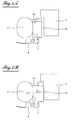
- the variation of the volume of the heating chamber as a function of the temperature of the degassing box is obtained by applying the principle of a division of the heating chamber into two sub-chambers and by acting on the communication between the latter.
- the heating chamber 54 is divided into two sub-chambers 56 and 57, which communicate with each other via a double wall 55. Inside this double wall 55 is inserted a plate 58 of paraffin-type material. .
- This paraffin-type material has the property of thermally insulating when cold and driving the heat when it is hot.
- the liquid of the sub-chamber 56 When the temperature in the degassing box 3 is warm, just after starting the vehicle, as shown in the diagram of the figure 8A the liquid of the sub-chamber 56, close to the degassing box 3, will heat up. Since the paraffin of the intermediate partition 55 has not yet reached its melting temperature, it is in the solid state and, consequently, isolates the second sub-chamber 57 from the first sub-chamber 56. The sub-chamber 57 remains cold, at a temperature T0.
- the liquid of the sub-chamber 56 will heat sufficiently to cause the liquefaction of the paraffin of the intermediate partition 55.
- the intermediate partition 55 having reached its melting temperature, it will become a heat conductor and, consequently, the second sub-chamber 57 will warm up (T greater than T0)
- the compartment serving as liquid reserve 2 can be dissociated from the assembly constituted by the heating chamber (24; 34; embodiments) and the degassing box compartment 3.
- the compartment acting as liquid reserve 2 could then be located elsewhere in the engine compartment or in another area of the vehicle.
Landscapes
- Engineering & Computer Science (AREA)
- Mechanical Engineering (AREA)
- Water Supply & Treatment (AREA)
- Chemical & Material Sciences (AREA)
- Combustion & Propulsion (AREA)
- General Engineering & Computer Science (AREA)
- Cleaning By Liquid Or Steam (AREA)
- Non-Portable Lighting Devices Or Systems Thereof (AREA)
Claims (14)
- Behälter für Waschflüssigkeit, insbesondere zum Waschen von Scheiben oder Scheinwerfern eines Kraftfahrzeugs, wobei der Behälter ein Fach aufweist, das als Entgasungsgehäuse (3) des Kühlkreislaufs des Motors dient, eine Heizkammer (23; 34; 44; 54) in Berührung mit dem Fach des Entgasungsgehäuses (3) und ein Fach, das als Waschflüssigkeitsreserve (2) dient, das von dem Fach des Entgasungsgehäuses (3) und von der Heizkammer (24; 34; 44; 54) getrennt ist, dadurch gekennzeichnet, dass der Behälter ferner ein Mittel aufweist, um das Heizen eines Teils der Waschflüssigkeit zu beschleunigen, wenn die Kühlflüssigkeit, die in dem Entgasungsgehäuse (3) enthalten ist, ihre optimale Betriebstemperatur noch nicht erreicht hat, indem das schnelle Heizen eines kleinen Teils von Flüssigkeit, der in der Heizkammer (24; 34; 44; 54) enthalten ist, erlaubt wird, bevor sie gepumpt wird.
- Behälter nach Anspruch 1, dadurch gekennzeichnet, dass das Mittel zum Beschleunigen des Heizens eines Teils der Waschflüssigkeit, wenn die Kühlflüssigkeit, die in dem Entgasungsgehäuse (3) enthalten ist, ihre optimale Betriebstemperatur noch nicht erreicht hat, aus einem Regulierrohr (17) mit variabler Länge ("L") besteht, das in der Heizkammer (24) platziert ist, wobei sich das Regulierrohr (17) verlängert und die wärmste Flüssigkeit pumpt, die sich in dem oberen Teil der Heizkammer (24) befindet.
- Behälter nach Anspruch 2, dadurch gekennzeichnet, dass das Regulierrohr (17) aus mindestens zwei Teilen gebildet ist: ein unteres Rohr (21) und ein oberes Rohr (22), die durch Verschieben im Inneren des unteren Rohrs (21) verlagert werden können, und dass Schwimmer (23) an dem oberen Teil des oberen Rohrs (22) derart befestigt sind, dass die Dichte erzielt wird, die es erlaubt, das obere Rohr (22) im Inneren des unteren Rohrs (21) zu schieben, wenn die Temperatur der Flüssigkeit zunimmt, und dadurch ein Regulierrohr (17) mit kleinerer Länge zu erzielen.
- Behälter nach Anspruch 3, dadurch gekennzeichnet, dass das obere Rohr (22) selbst aus mehreren Rohrabschnitten besteht, die jeweils als oberes Rohr dienen, das unter der Einwirkung der Änderung der Dichte der Flüssigkeit derart beweglich ist, dass es sich an die Geometrie des Behälters anpasst.
- Behälter nach Anspruch 1, dadurch gekennzeichnet, dass das Mittel zum Beschleunigen des Heizens eines Teils der Waschflüssigkeit, wenn die Kühlflüssigkeit, die in dem Entgasungsgehäuse (3) enthalten ist, noch nicht ihre optimale Betriebstemperatur erreicht hat, aus einem Mittel zum Verringern des Volumens der Heizkammer (34; 44; 54) derart besteht, dass weniger Flüssigkeit zu heizen ist.
- Behälter nach Anspruch 5, dadurch gekennzeichnet, dass das Mittel zum Verringern des Volumens der Heizkammer (34) aus mindestens einem Teil der Heizkammer besteht, der aus einem Material mit Formgedächtnis hergestellt ist, wobei die Geometrie des Teils mit Formgedächtnis variiert, wenn die Temperatur der Flüssigkeit einen vorbestimmten Schwellenwert überschreitet.
- Behälter nach Anspruch 6, dadurch gekennzeichnet, dass der Teil der Heizkammer (34), der aus einem Material mit Formgedächtnis hergestellt ist, eine Wand (35) der Heizkammer (34) ist, wobei die Wand (35) konkave Form hat, wenn die Kühlflüssigkeit, die in dem Entgasungsgehäuse (3) enthalten ist, ihre optimale Betriebstemperatur noch nicht erreicht hat, und die eine konvexe Form annimmt, wenn die Flüssigkeit ihre optimale Betriebstemperatur erreicht hat.
- Behälter nach Anspruch 5, dadurch gekennzeichnet, dass das Mittel zum Verringern des Volumens der Heizkammer (44) aus einer beweglichen Wand (45) besteht, die durch Verschieben unter der Einwirkung der Druckerhöhung in dem Entgasungsgehäuse (3), wenn dessen Temperatur ansteigt, verlagert wird.
- Behälter nach Anspruch 8, dadurch gekennzeichnet, dass sich die bewegliche Wand (45) unter der Einwirkung mindestens eines Kolbens verschiebt.
- Behälter nach Anspruch 5, dadurch gekennzeichnet, dass das Mittel zum Verringern des Volumens der Heizkammer (54) aus der Tatsache besteht, dass die Heizkammer (54) in zwei Unterkammern (56, 57) unterteilt ist, die untereinander über eine Zwischenwand (55) verbunden sind, die ein Material enthält, das die Unterkammern (56, 57) voneinander wärmeisoliert, wenn die Kühlflüssigkeit, die in dem Entgasungsgehäuse (3) enthalten ist, ihre optimale Betriebstemperatur noch nicht erreicht hat, und das die Wärme leitet, wenn die Flüssigkeit ihre optimale Betriebstemperatur erreicht hat.
- Behälter nach Anspruch 10, dadurch gekennzeichnet, dass das Material der Zwischenwand (55) ein Material des Typs Paraffin ist.
- Behälter nach den Ansprüchen 10 und 11, dadurch gekennzeichnet, dass die Zwischenwand (55) eine doppelte Wand ist und dass das Material der Zwischenwand (55) ein Material in Form einer Platte ist, das in das Innere der doppelten Wand eingefügt ist.
- Waschflüssigkeitsverteilungssystem insbesondere der Scheiben oder Scheinwerfer eines Kraftfahrzeugs, dadurch gekennzeichnet, dass der Behälter die Waschflüssigkeitsreserve und das Entgasungsgehäuse des Kühlkreislaufs des Motors kompaktiert und dass der Behälter ein Behälter nach einem der Ansprüche 1 bis 12 ist.
- Kraftfahrzeug, dadurch gekennzeichnet, dass es ein Waschflüssigkeitsverteilungssystem aufweist, insbesondere zum Waschen der Scheiben oder der Scheinwerfer, das dem Verteilungssystem des Anspruchs 13 entspricht.
Applications Claiming Priority (1)
| Application Number | Priority Date | Filing Date | Title |
|---|---|---|---|
| FR0858449A FR2939387B1 (fr) | 2008-12-10 | 2008-12-10 | Reservoir de liquide de lavage, en particulier des vitres ou des projecteurs, pour un vehicule automobile |
Publications (2)
| Publication Number | Publication Date |
|---|---|
| EP2196367A1 EP2196367A1 (de) | 2010-06-16 |
| EP2196367B1 true EP2196367B1 (de) | 2012-02-08 |
Family
ID=40800163
Family Applications (1)
| Application Number | Title | Priority Date | Filing Date |
|---|---|---|---|
| EP09178728A Not-in-force EP2196367B1 (de) | 2008-12-10 | 2009-12-10 | Waschwasserbehälter, insbesondere für Scheiben oder Scheinwerfer in einem Kraftfahrzeug |
Country Status (3)
| Country | Link |
|---|---|
| EP (1) | EP2196367B1 (de) |
| AT (1) | ATE544643T1 (de) |
| FR (1) | FR2939387B1 (de) |
Cited By (1)
| Publication number | Priority date | Publication date | Assignee | Title |
|---|---|---|---|---|
| CN105247182A (zh) * | 2012-09-06 | 2016-01-13 | 大陆汽车有限公司 | 用于工作流体的塑料储罐 |
Families Citing this family (3)
| Publication number | Priority date | Publication date | Assignee | Title |
|---|---|---|---|---|
| FR3002901B1 (fr) * | 2013-03-06 | 2015-02-27 | Peugeot Citroen Automobiles Sa | Dispositif de rechauffage de liquide lave-vitre d'un reservoir additionnel a volume variable d'un vehicule |
| FR3011212B1 (fr) * | 2013-09-27 | 2015-10-23 | Peugeot Citroen Automobiles Sa | Dispositif de reglage de la temperature d'un liquide lave-vitres d'un resevoir additionnel d'un vehicule |
| EP3715192A1 (de) * | 2019-03-26 | 2020-09-30 | Ningbo Geely Automobile Research & Development Co. Ltd. | Waschflüssigkeitsanordnung |
Family Cites Families (4)
| Publication number | Priority date | Publication date | Assignee | Title |
|---|---|---|---|---|
| US4090668A (en) * | 1976-12-06 | 1978-05-23 | Kochenour Paul R | Windshield washer and deicer |
| GB9221323D0 (en) * | 1992-10-10 | 1992-11-25 | Mackay Robert | Hot screen wash conversion |
| FR2875763B1 (fr) * | 2004-09-30 | 2006-12-22 | Peugeot Citroen Automobiles Sa | Dispositif de rechauffage de l'eau des lave-vitres d'un vehicule automobile |
| FR2884477B1 (fr) * | 2005-04-14 | 2008-12-19 | Coutier Moulage Gen Ind | Reservoir comportant des moyens de chauffage pour un liquide de lavage a pulveriser sur des vitres ou projecteurs d'un vehicule automobile |
-
2008
- 2008-12-10 FR FR0858449A patent/FR2939387B1/fr not_active Expired - Fee Related
-
2009
- 2009-12-10 EP EP09178728A patent/EP2196367B1/de not_active Not-in-force
- 2009-12-10 AT AT09178728T patent/ATE544643T1/de active
Cited By (2)
| Publication number | Priority date | Publication date | Assignee | Title |
|---|---|---|---|---|
| CN105247182A (zh) * | 2012-09-06 | 2016-01-13 | 大陆汽车有限公司 | 用于工作流体的塑料储罐 |
| CN105247182B (zh) * | 2012-09-06 | 2021-09-24 | 大陆汽车有限公司 | 用于工作流体的塑料储罐 |
Also Published As
| Publication number | Publication date |
|---|---|
| EP2196367A1 (de) | 2010-06-16 |
| FR2939387B1 (fr) | 2011-01-14 |
| ATE544643T1 (de) | 2012-02-15 |
| FR2939387A1 (fr) | 2010-06-11 |
Similar Documents
| Publication | Publication Date | Title |
|---|---|---|
| EP2196367B1 (de) | Waschwasserbehälter, insbesondere für Scheiben oder Scheinwerfer in einem Kraftfahrzeug | |
| EP3922148B1 (de) | Heizkessel für getränkezubereitungsmaschine | |
| FR2893398A1 (fr) | Unite de reservoir d'emmagasinage de froid et dispositif de cycle de refrigeration utilisant celle-ci | |
| EP1164341B1 (de) | Selbstkühlende Getränkeverpackung | |
| EP2164728B1 (de) | Verfahren zur herstellung eines behälters für flüssigkeiten zum waschen der glasflächen eines motorfahrzeugs und nach diesem verfahren hergestellter behälter | |
| EP2756251A1 (de) | Kapillarpumpen-wärmetransportvorrichtung | |
| FR3074842A1 (fr) | Reservoir de liquide a multiples compartiments pour un vehicule automobile | |
| EP1290387B1 (de) | Verfahren zur herstellung einer selbstkühlenden getränkeverpackung und vorrichtung zur durchführung des verfahrens | |
| FR2905737A1 (fr) | Procede et dispositif pour prechauffer le moteur a combustion interne d'un vehicule automobile | |
| EP1794041B1 (de) | Vorrichtung zur wiederaufwärmung des wassers einer scheibenwaschanlage eines kraftfahrzeugs | |
| EP2162323B1 (de) | Waschflüssigkeitstank für ein automobil | |
| FR2884477A1 (fr) | Reservoir comportant des moyens de chauffage pour un liquide de lavage a pulveriser sur des vitres ou projecteurs d'un vehicule automobile | |
| EP2176101B1 (de) | Vorrichtung zur wiederaufwärmung des wassers einer scheibenwaschanlage eines kraftfahrzeugs | |
| EP2219909B1 (de) | Waschflüssigkeitsbehälter für ein kraftfahrzeug | |
| EP1909023B1 (de) | Verfahren und Vorrichtung zur Lagerung von kryogenen Fluiden | |
| FR2985483A1 (fr) | Reservoir de liquide de lavage, notamment pour vehicule, et dispositif de lavage integrant un tel reservoir | |
| FR2947502A1 (fr) | Reservoir de liquide de lavage avec une chambre de melange chauffee et regulee thermiquement et dispositif de lavage contenant un tel reservoir pour un vehicule automobile | |
| FR2899185A1 (fr) | Dispositif perfectionne pour le rechauffage de l'eau des lave-vitres d'un vehicule automobile | |
| EP2213858B1 (de) | Vorrichtung zum Wiederaufwärmen der Scheibenwischflüssigkeit eines Kraftfahrzeugs | |
| EP1584876B1 (de) | Speisetransportwagen mit doppelter, mitgeführter Kältereserve | |
| FR2971982A1 (fr) | Palier de mecanisme d'essuie-vitre presentant des moyens d'evacuation de l'eau sur la paroi de son alesage | |
| EP3862715A1 (de) | Reversibler wärmetauscher mit doppeltem transportkreislauf | |
| FR2918619A1 (fr) | PERFECTIONNEMENT AUX DISPOSITIFS DE RECHAUFFAGE DE l'EAU D'UN LAVE GLACE POUR VEHICULE AUTOMOBILE. | |
| FR2538088A1 (fr) | Appareil de transmission de chaleur | |
| FR2929331A1 (fr) | Moteur de vehicule comprenant un dispositif de refroidissement de la zone inter-soupapes |
Legal Events
| Date | Code | Title | Description |
|---|---|---|---|
| PUAI | Public reference made under article 153(3) epc to a published international application that has entered the european phase |
Free format text: ORIGINAL CODE: 0009012 |
|
| AK | Designated contracting states |
Kind code of ref document: A1 Designated state(s): AT BE BG CH CY CZ DE DK EE ES FI FR GB GR HR HU IE IS IT LI LT LU LV MC MK MT NL NO PL PT RO SE SI SK SM TR |
|
| AX | Request for extension of the european patent |
Extension state: AL BA RS |
|
| 17P | Request for examination filed |
Effective date: 20101210 |
|
| RIC1 | Information provided on ipc code assigned before grant |
Ipc: B60S 1/48 20060101AFI20110630BHEP Ipc: F01P 3/10 20060101ALI20110630BHEP Ipc: B60S 1/50 20060101ALI20110630BHEP |
|
| GRAP | Despatch of communication of intention to grant a patent |
Free format text: ORIGINAL CODE: EPIDOSNIGR1 |
|
| GRAS | Grant fee paid |
Free format text: ORIGINAL CODE: EPIDOSNIGR3 |
|
| GRAA | (expected) grant |
Free format text: ORIGINAL CODE: 0009210 |
|
| AK | Designated contracting states |
Kind code of ref document: B1 Designated state(s): AT BE BG CH CY CZ DE DK EE ES FI FR GB GR HR HU IE IS IT LI LT LU LV MC MK MT NL NO PL PT RO SE SI SK SM TR |
|
| REG | Reference to a national code |
Ref country code: GB Ref legal event code: FG4D Free format text: NOT ENGLISH |
|
| REG | Reference to a national code |
Ref country code: CH Ref legal event code: EP Ref country code: AT Ref legal event code: REF Ref document number: 544643 Country of ref document: AT Kind code of ref document: T Effective date: 20120215 |
|
| REG | Reference to a national code |
Ref country code: DE Ref legal event code: R096 Ref document number: 602009005187 Country of ref document: DE Effective date: 20120405 |
|
| REG | Reference to a national code |
Ref country code: NL Ref legal event code: VDEP Effective date: 20120208 |
|
| LTIE | Lt: invalidation of european patent or patent extension |
Effective date: 20120208 |
|
| REG | Reference to a national code |
Ref country code: GB Ref legal event code: 746 Effective date: 20120702 |
|
| PG25 | Lapsed in a contracting state [announced via postgrant information from national office to epo] |
Ref country code: NL Free format text: LAPSE BECAUSE OF FAILURE TO SUBMIT A TRANSLATION OF THE DESCRIPTION OR TO PAY THE FEE WITHIN THE PRESCRIBED TIME-LIMIT Effective date: 20120208 Ref country code: IS Free format text: LAPSE BECAUSE OF FAILURE TO SUBMIT A TRANSLATION OF THE DESCRIPTION OR TO PAY THE FEE WITHIN THE PRESCRIBED TIME-LIMIT Effective date: 20120608 Ref country code: LT Free format text: LAPSE BECAUSE OF FAILURE TO SUBMIT A TRANSLATION OF THE DESCRIPTION OR TO PAY THE FEE WITHIN THE PRESCRIBED TIME-LIMIT Effective date: 20120208 Ref country code: HR Free format text: LAPSE BECAUSE OF FAILURE TO SUBMIT A TRANSLATION OF THE DESCRIPTION OR TO PAY THE FEE WITHIN THE PRESCRIBED TIME-LIMIT Effective date: 20120208 Ref country code: NO Free format text: LAPSE BECAUSE OF FAILURE TO SUBMIT A TRANSLATION OF THE DESCRIPTION OR TO PAY THE FEE WITHIN THE PRESCRIBED TIME-LIMIT Effective date: 20120508 |
|
| REG | Reference to a national code |
Ref country code: DE Ref legal event code: R084 Ref document number: 602009005187 Country of ref document: DE Effective date: 20120619 |
|
| REG | Reference to a national code |
Ref country code: IE Ref legal event code: FD4D |
|
| PG25 | Lapsed in a contracting state [announced via postgrant information from national office to epo] |
Ref country code: PL Free format text: LAPSE BECAUSE OF FAILURE TO SUBMIT A TRANSLATION OF THE DESCRIPTION OR TO PAY THE FEE WITHIN THE PRESCRIBED TIME-LIMIT Effective date: 20120208 Ref country code: GR Free format text: LAPSE BECAUSE OF FAILURE TO SUBMIT A TRANSLATION OF THE DESCRIPTION OR TO PAY THE FEE WITHIN THE PRESCRIBED TIME-LIMIT Effective date: 20120509 Ref country code: LV Free format text: LAPSE BECAUSE OF FAILURE TO SUBMIT A TRANSLATION OF THE DESCRIPTION OR TO PAY THE FEE WITHIN THE PRESCRIBED TIME-LIMIT Effective date: 20120208 Ref country code: FI Free format text: LAPSE BECAUSE OF FAILURE TO SUBMIT A TRANSLATION OF THE DESCRIPTION OR TO PAY THE FEE WITHIN THE PRESCRIBED TIME-LIMIT Effective date: 20120208 Ref country code: PT Free format text: LAPSE BECAUSE OF FAILURE TO SUBMIT A TRANSLATION OF THE DESCRIPTION OR TO PAY THE FEE WITHIN THE PRESCRIBED TIME-LIMIT Effective date: 20120608 |
|
| REG | Reference to a national code |
Ref country code: AT Ref legal event code: MK05 Ref document number: 544643 Country of ref document: AT Kind code of ref document: T Effective date: 20120208 |
|
| PG25 | Lapsed in a contracting state [announced via postgrant information from national office to epo] |
Ref country code: CY Free format text: LAPSE BECAUSE OF FAILURE TO SUBMIT A TRANSLATION OF THE DESCRIPTION OR TO PAY THE FEE WITHIN THE PRESCRIBED TIME-LIMIT Effective date: 20120208 |
|
| PG25 | Lapsed in a contracting state [announced via postgrant information from national office to epo] |
Ref country code: DK Free format text: LAPSE BECAUSE OF FAILURE TO SUBMIT A TRANSLATION OF THE DESCRIPTION OR TO PAY THE FEE WITHIN THE PRESCRIBED TIME-LIMIT Effective date: 20120208 Ref country code: IE Free format text: LAPSE BECAUSE OF FAILURE TO SUBMIT A TRANSLATION OF THE DESCRIPTION OR TO PAY THE FEE WITHIN THE PRESCRIBED TIME-LIMIT Effective date: 20120208 Ref country code: RO Free format text: LAPSE BECAUSE OF FAILURE TO SUBMIT A TRANSLATION OF THE DESCRIPTION OR TO PAY THE FEE WITHIN THE PRESCRIBED TIME-LIMIT Effective date: 20120208 Ref country code: SI Free format text: LAPSE BECAUSE OF FAILURE TO SUBMIT A TRANSLATION OF THE DESCRIPTION OR TO PAY THE FEE WITHIN THE PRESCRIBED TIME-LIMIT Effective date: 20120208 Ref country code: CZ Free format text: LAPSE BECAUSE OF FAILURE TO SUBMIT A TRANSLATION OF THE DESCRIPTION OR TO PAY THE FEE WITHIN THE PRESCRIBED TIME-LIMIT Effective date: 20120208 Ref country code: SE Free format text: LAPSE BECAUSE OF FAILURE TO SUBMIT A TRANSLATION OF THE DESCRIPTION OR TO PAY THE FEE WITHIN THE PRESCRIBED TIME-LIMIT Effective date: 20120208 Ref country code: EE Free format text: LAPSE BECAUSE OF FAILURE TO SUBMIT A TRANSLATION OF THE DESCRIPTION OR TO PAY THE FEE WITHIN THE PRESCRIBED TIME-LIMIT Effective date: 20120208 |
|
| PG25 | Lapsed in a contracting state [announced via postgrant information from national office to epo] |
Ref country code: IT Free format text: LAPSE BECAUSE OF FAILURE TO SUBMIT A TRANSLATION OF THE DESCRIPTION OR TO PAY THE FEE WITHIN THE PRESCRIBED TIME-LIMIT Effective date: 20120208 Ref country code: SK Free format text: LAPSE BECAUSE OF FAILURE TO SUBMIT A TRANSLATION OF THE DESCRIPTION OR TO PAY THE FEE WITHIN THE PRESCRIBED TIME-LIMIT Effective date: 20120208 |
|
| PLBE | No opposition filed within time limit |
Free format text: ORIGINAL CODE: 0009261 |
|
| STAA | Information on the status of an ep patent application or granted ep patent |
Free format text: STATUS: NO OPPOSITION FILED WITHIN TIME LIMIT |
|
| 26N | No opposition filed |
Effective date: 20121109 |
|
| PG25 | Lapsed in a contracting state [announced via postgrant information from national office to epo] |
Ref country code: AT Free format text: LAPSE BECAUSE OF FAILURE TO SUBMIT A TRANSLATION OF THE DESCRIPTION OR TO PAY THE FEE WITHIN THE PRESCRIBED TIME-LIMIT Effective date: 20120208 |
|
| REG | Reference to a national code |
Ref country code: DE Ref legal event code: R097 Ref document number: 602009005187 Country of ref document: DE Effective date: 20121109 |
|
| PG25 | Lapsed in a contracting state [announced via postgrant information from national office to epo] |
Ref country code: ES Free format text: LAPSE BECAUSE OF FAILURE TO SUBMIT A TRANSLATION OF THE DESCRIPTION OR TO PAY THE FEE WITHIN THE PRESCRIBED TIME-LIMIT Effective date: 20120519 |
|
| BERE | Be: lapsed |
Owner name: PEUGEOT CITROEN AUTOMOBILES SA Effective date: 20121231 |
|
| PG25 | Lapsed in a contracting state [announced via postgrant information from national office to epo] |
Ref country code: MC Free format text: LAPSE BECAUSE OF NON-PAYMENT OF DUE FEES Effective date: 20121231 Ref country code: BG Free format text: LAPSE BECAUSE OF FAILURE TO SUBMIT A TRANSLATION OF THE DESCRIPTION OR TO PAY THE FEE WITHIN THE PRESCRIBED TIME-LIMIT Effective date: 20120508 |
|
| PG25 | Lapsed in a contracting state [announced via postgrant information from national office to epo] |
Ref country code: BE Free format text: LAPSE BECAUSE OF NON-PAYMENT OF DUE FEES Effective date: 20121231 |
|
| PG25 | Lapsed in a contracting state [announced via postgrant information from national office to epo] |
Ref country code: MT Free format text: LAPSE BECAUSE OF FAILURE TO SUBMIT A TRANSLATION OF THE DESCRIPTION OR TO PAY THE FEE WITHIN THE PRESCRIBED TIME-LIMIT Effective date: 20120208 |
|
| PG25 | Lapsed in a contracting state [announced via postgrant information from national office to epo] |
Ref country code: TR Free format text: LAPSE BECAUSE OF FAILURE TO SUBMIT A TRANSLATION OF THE DESCRIPTION OR TO PAY THE FEE WITHIN THE PRESCRIBED TIME-LIMIT Effective date: 20120208 |
|
| PG25 | Lapsed in a contracting state [announced via postgrant information from national office to epo] |
Ref country code: SM Free format text: LAPSE BECAUSE OF FAILURE TO SUBMIT A TRANSLATION OF THE DESCRIPTION OR TO PAY THE FEE WITHIN THE PRESCRIBED TIME-LIMIT Effective date: 20120208 Ref country code: LU Free format text: LAPSE BECAUSE OF NON-PAYMENT OF DUE FEES Effective date: 20121210 |
|
| PG25 | Lapsed in a contracting state [announced via postgrant information from national office to epo] |
Ref country code: HU Free format text: LAPSE BECAUSE OF FAILURE TO SUBMIT A TRANSLATION OF THE DESCRIPTION OR TO PAY THE FEE WITHIN THE PRESCRIBED TIME-LIMIT Effective date: 20091210 |
|
| REG | Reference to a national code |
Ref country code: CH Ref legal event code: PL |
|
| PG25 | Lapsed in a contracting state [announced via postgrant information from national office to epo] |
Ref country code: LI Free format text: LAPSE BECAUSE OF NON-PAYMENT OF DUE FEES Effective date: 20131231 Ref country code: CH Free format text: LAPSE BECAUSE OF NON-PAYMENT OF DUE FEES Effective date: 20131231 |
|
| PGFP | Annual fee paid to national office [announced via postgrant information from national office to epo] |
Ref country code: GB Payment date: 20141126 Year of fee payment: 6 Ref country code: DE Payment date: 20141121 Year of fee payment: 6 |
|
| PG25 | Lapsed in a contracting state [announced via postgrant information from national office to epo] |
Ref country code: MK Free format text: LAPSE BECAUSE OF FAILURE TO SUBMIT A TRANSLATION OF THE DESCRIPTION OR TO PAY THE FEE WITHIN THE PRESCRIBED TIME-LIMIT Effective date: 20120208 |
|
| REG | Reference to a national code |
Ref country code: FR Ref legal event code: PLFP Year of fee payment: 7 |
|
| PGFP | Annual fee paid to national office [announced via postgrant information from national office to epo] |
Ref country code: FR Payment date: 20151123 Year of fee payment: 7 |
|
| REG | Reference to a national code |
Ref country code: DE Ref legal event code: R119 Ref document number: 602009005187 Country of ref document: DE |
|
| GBPC | Gb: european patent ceased through non-payment of renewal fee |
Effective date: 20151210 |
|
| PG25 | Lapsed in a contracting state [announced via postgrant information from national office to epo] |
Ref country code: GB Free format text: LAPSE BECAUSE OF NON-PAYMENT OF DUE FEES Effective date: 20151210 Ref country code: DE Free format text: LAPSE BECAUSE OF NON-PAYMENT OF DUE FEES Effective date: 20160701 |
|
| REG | Reference to a national code |
Ref country code: FR Ref legal event code: ST Effective date: 20170831 |
|
| PG25 | Lapsed in a contracting state [announced via postgrant information from national office to epo] |
Ref country code: FR Free format text: LAPSE BECAUSE OF NON-PAYMENT OF DUE FEES Effective date: 20170102 |