EP2196367B1 - Washing liquid tank, in particular for windows or projectors of a vehicle - Google Patents
Washing liquid tank, in particular for windows or projectors of a vehicle Download PDFInfo
- Publication number
- EP2196367B1 EP2196367B1 EP09178728A EP09178728A EP2196367B1 EP 2196367 B1 EP2196367 B1 EP 2196367B1 EP 09178728 A EP09178728 A EP 09178728A EP 09178728 A EP09178728 A EP 09178728A EP 2196367 B1 EP2196367 B1 EP 2196367B1
- Authority
- EP
- European Patent Office
- Prior art keywords
- liquid
- heating chamber
- reservoir
- tube
- washing liquid
- Prior art date
- Legal status (The legal status is an assumption and is not a legal conclusion. Google has not performed a legal analysis and makes no representation as to the accuracy of the status listed.)
- Not-in-force
Links
Images


Classifications
-
- B—PERFORMING OPERATIONS; TRANSPORTING
- B60—VEHICLES IN GENERAL
- B60S—SERVICING, CLEANING, REPAIRING, SUPPORTING, LIFTING, OR MANOEUVRING OF VEHICLES, NOT OTHERWISE PROVIDED FOR
- B60S1/00—Cleaning of vehicles
- B60S1/02—Cleaning windscreens, windows or optical devices
- B60S1/46—Cleaning windscreens, windows or optical devices using liquid; Windscreen washers
- B60S1/48—Liquid supply therefor
- B60S1/50—Arrangement of reservoir
-
- B—PERFORMING OPERATIONS; TRANSPORTING
- B60—VEHICLES IN GENERAL
- B60S—SERVICING, CLEANING, REPAIRING, SUPPORTING, LIFTING, OR MANOEUVRING OF VEHICLES, NOT OTHERWISE PROVIDED FOR
- B60S1/00—Cleaning of vehicles
- B60S1/02—Cleaning windscreens, windows or optical devices
- B60S1/46—Cleaning windscreens, windows or optical devices using liquid; Windscreen washers
- B60S1/48—Liquid supply therefor
- B60S1/487—Liquid supply therefor the liquid being heated
-
- F—MECHANICAL ENGINEERING; LIGHTING; HEATING; WEAPONS; BLASTING
- F01—MACHINES OR ENGINES IN GENERAL; ENGINE PLANTS IN GENERAL; STEAM ENGINES
- F01P—COOLING OF MACHINES OR ENGINES IN GENERAL; COOLING OF INTERNAL-COMBUSTION ENGINES
- F01P11/00—Component parts, details, or accessories not provided for in, or of interest apart from, groups F01P1/00 - F01P9/00
- F01P11/02—Liquid-coolant filling, overflow, venting, or draining devices
- F01P11/029—Expansion reservoirs
Definitions
- the present invention relates to a tank of washing liquid, in particular windows or projectors, for a motor vehicle.
- It relates more particularly to a reservoir - or jar - of "bi-function" type, in which the reserve of washing liquid itself and the degassing box of the engine cooling circuit are compacted in one piece.
- This type of tank makes it possible to heat the washing liquid of windows or projectors by recovering calories from the coolant.
- Such a type of tank is known from the document FR 07 08068 , which describes a tank provided with a partition separating a first chamber, called “cold room”, having in its upper part at least one liquid filling orifice, and a second chamber, called “hot room”, comprising in its part less than at least one pumping orifice.
- the hot chamber has a partition common to a reheating body, such as a degassing chamber, so as to ensure the reheating of the liquid contained in the hot chamber.
- the hot chamber communicates with the cold room by at least one communication orifice formed in the partition wall to allow the filling of the hot chamber from the cold room.
- the pumping orifice of the hot chamber is extended towards the inside of said hot chamber by a column for evacuating the contents of the hot chamber.
- This evacuation column is fed with liquid through at least one opening, called “high opening”, remote from the base of the column.
- the discharge column has an additional liquid supply opening of the evacuation column, called “low opening”, which is located at a level lower than that of the upper opening and, preferably, at the base or in the vicinity of the base of the column.
- the tanks known in the prior art and their components have a relatively "frozen" geometry, that is to say identical regardless of, for example, the temperature of the coolant or the outside temperature. This is the case, for example, with the height of the regulation tube, which conditions the temperature of the washing liquid sucked by the pump. As a result, the performance of the washing liquid system is not the same at the start of the vehicle (warm engine) and after several minutes of driving the vehicle (hot engine).
- FR-A-2884477 shows the preamble of claim 1
- the object of the present invention is to provide a tank of washing liquid, in particular windows or projectors, for a motor vehicle, which has an optimal operation and allows in particular the heating of the washing liquid at the start of the vehicle when the liquid
- the coolant contained in the degassing box has not yet reached its optimum operating temperature, allowing rapid heating of a small portion of liquid contained in the heating chamber before being pumped.
- Another object of the present invention is to provide such a reservoir of washing liquid, which allows a rapid increase in the temperature of the washing liquid after starting the vehicle.
- Another object of the present invention is to provide such a washing liquid reservoir, which operates without causing disturbance in the temperature rise of the degassing box after starting and during the rolling of the vehicle.
- the subject of the present invention is a washing liquid reservoir, in particular windows or projectors, of a motor vehicle, which reservoir comprises a compartment acting as a degassing box of the engine cooling circuit. a heating chamber in contact with said degassing box compartment, a compartment serving as a wash liquid reserve, isolated from the degassing box compartment and the heating chamber, and this new reservoir further comprises means for accelerating the heating of a part of the washing liquid when the coolant contained in the degassing box has not yet reached its optimum operating temperature , thus allowing the rapid heating of a small portion of liquid contained in the heating chamber which is then pumped.
- the means for accelerating the heating of a portion of the washing liquid when the cooling liquid contained in the degassing box has not yet reached its optimum operating temperature can advantageously be consisting of a regulating tube, of variable length, placed in the heating chamber, which regulating tube is lengthened and pump the hottest liquid located in the upper part of said heating chamber.
- control tube of variable length
- the control tube is formed of at least two parts: a lower tube and an upper tube that can be moved by translation inside the lower tube, and floats are fixed to the part upper tube, so as to obtain the density that allows to slide the upper tube inside the lower tube when the temperature of the liquid increases.
- the upper tube may itself be composed of several pipe sections each acting as a mobile upper tube under the effect of the density change of the liquid, so as to adapt to the geometry of the reservoir.
- the means for accelerating the heating of a part of the washing liquid when the coolant contained in the degassing box has not yet reached its optimum operating temperature is constituted by means of reducing the volume of the heating chamber, so as to have less liquid to heat.
- This means of reducing the volume of the heating chamber may advantageously consist of at least a portion of the heating chamber, which is manufactured in a shape memory material, the geometry of said shape memory portion varying when the temperature liquid exceeds a predetermined threshold.
- the portion of shape memory material is a partition of the heating chamber, which is concave when the coolant contained in the degassing box has not yet reached its optimum operating temperature and takes a convex shape when said liquid reaches its optimum operating temperature.
- the means for reducing the volume of the heating chamber may be constituted by a movable partition, which is displaced by translation under the effect of the increase in pressure in the degassing box when the latter rises in temperature.
- This movable partition can move under the action of at least one piston, for example.
- the means for reducing the volume of the heating chamber may be constituted by a division of the heating chamber into two sub-chambers, which communicate with each other via an intermediate partition comprising a material which thermally isolates the sub-chambers relative to each other when the coolant contained in the degassing box has not yet reached its optimum operating temperature and which conducts the heat when said liquid has reached its optimum temperature Operating.
- this material of the intermediate partition may be a paraffin-type material.
- the intermediate partition may be a double wall, and the material of the intermediate partition may be a plate-shaped material inserted within the double wall.
- the present invention also relates to a washing liquid distribution system, in particular windows or projectors, of a motor vehicle, and this new dispensing system comprises a reservoir which compact the washing liquid reservoir and the box. degassing the engine cooling circuit, and bi-function tank is in line with that described above in outline.
- the present invention finally relates to a motor vehicle, which comprises a washing liquid distribution system, in particular for windows and projectors, which is in accordance with the distribution system described above in outline.
- a bi-function tank of general reference 1, comprising, in known manner, a compacted assembly comprising the washing liquid reserve chamber 2 and the degassing box 3 of the engine cooling circuit.
- the washing liquid reserve chamber 2 which contains most of the window or head washing liquid, is thermally insulated from the degassing box 3 and the heating chamber 4 by an air gap 6 in order to did not pump calories.
- the heating chamber 4 is located on the side of the degassing box 3
- the pump 8 is located at the lowest possible point of the available volume of this chamber 4, and a regulation tube 7 makes it possible to suck in priority the hottest washing liquid.
- the height of the regulation tube 7 conditions the temperature of the washing liquid sucked by the pump 8, the hot liquid being at the top of the heating chamber 4, while the liquid in the lower zone of the chamber is colder.
- Calibrated orifices make it possible to connect the different compartments of the tank; thus, an orifice 9 allows pumping of the hot liquid when the level is low and an orifice 10 allows the filling of the heating chamber 4.
- a means for optimizing the operation of the reservoir in particular the heating of the washing liquid when the coolant contained in the degassing box 3 has not yet reached its optimum temperature.
- This means of the invention allows the rapid heating of a small portion of washing liquid which will then be pumped.
- the hottest liquid is pumped from the heating chamber 4, therefore the liquid located in the upper part thereof.
- Such a selective action is possible by lengthening the regulation tube 7 ( Figure 4A ).
- the liquid has had time to heat and so not to pump a liquid that is too hot and that may lead to burns, it is necessary to reduce the length of the regulation tube 7 ( Figure 4B ).
- the implementation of this principle of the invention requires, therefore, the realization of a regulation tube 7 whose length "L" is variable depending on the temperature of the liquid in the heating chamber 4.
- variable length of the regulation tube is obtained by applying a principle of "buoyancy" of the bodies in a liquid.
- the regulation tube 17 of the Figures 5A and 5B consists of two parts: a fixed lower tube 21, provided at its upper part with a bore 21a serving as a guide bearing for the translational movement of a movable tube or "upper tube” 22.
- the upper tube 22 is extended at its lower end by a base or collar 22a for retaining it in the lower tube 21.
- Floats 23 are arranged on the upper tube 22, preferably at its upper end or in the vicinity of the latter.
- control tube 17 thus designed to pump the hottest liquid from the heating chamber 4 first after the vehicle has started, and then when the vehicle is traveling and the engine is hot. , to pump a liquid that is not the hottest so as to avoid any risk of burns.
- Another solution for accelerating the heating of the liquid after starting the vehicle is to reduce the volume of the heating chamber. This solution is based on the principle that by decreasing the amount of liquid to be heated, heating is faster. On the other hand, once the optimum temperature is reached, it is necessary to increase the volume of the heating chamber so as to have a larger quantity of hot liquid.
- the variation of the volume of the heating chamber as a function of the temperature of the degassing box is obtained by applying the principle of a variable partition called "shape memory partition".
- the heating chamber is designated by the reference 34. At least a portion of this chamber 34 is made of a shape memory material and is shown schematically on the Figures 6A and 6B by a partition referenced 35.
- a shape memory material is a material that has a given geometry in a certain temperature range and another geometry, different, predetermined, when the temperature exceeds a certain threshold. It is very schematically represented on the Figure 6A partition 35 at starting the vehicle, the engine being warm and the volume of liquid to be heated being relatively low due to the concave shape of the partition 35. During the driving of the vehicle, the engine is now hot, the volume of the heating chamber 34 s It enlarges because of the variation of the shape of the partition 35 which has become convex by crossing a predetermined temperature.
- the modification of the position of the partition of the heating chamber according to the temperature of the degassing box is obtained by moving the partition by translation with the aid of one or more pistons.
- the heating chamber 44 comprises a partition 45 which is displaced by translation along the arrow F, so as to enlarge its volume.
- This translation F is exerted by increasing the pressure P in the degassing box 3 due to the increase in temperature in the latter.
- the increase in the pressure P causes the displacement of the piston (s) (not shown) in the direction of the arrow F of the Figure 7B , on which is shown schematically the heating chamber 44 in volume extension during the rolling of the vehicle, the engine then being relatively hot.
- the variation of the volume of the heating chamber as a function of the temperature of the degassing box is obtained by applying the principle of a division of the heating chamber into two sub-chambers and by acting on the communication between the latter.
- the heating chamber 54 is divided into two sub-chambers 56 and 57, which communicate with each other via a double wall 55. Inside this double wall 55 is inserted a plate 58 of paraffin-type material. .
- This paraffin-type material has the property of thermally insulating when cold and driving the heat when it is hot.
- the liquid of the sub-chamber 56 When the temperature in the degassing box 3 is warm, just after starting the vehicle, as shown in the diagram of the figure 8A the liquid of the sub-chamber 56, close to the degassing box 3, will heat up. Since the paraffin of the intermediate partition 55 has not yet reached its melting temperature, it is in the solid state and, consequently, isolates the second sub-chamber 57 from the first sub-chamber 56. The sub-chamber 57 remains cold, at a temperature T0.
- the liquid of the sub-chamber 56 will heat sufficiently to cause the liquefaction of the paraffin of the intermediate partition 55.
- the intermediate partition 55 having reached its melting temperature, it will become a heat conductor and, consequently, the second sub-chamber 57 will warm up (T greater than T0)
- the compartment serving as liquid reserve 2 can be dissociated from the assembly constituted by the heating chamber (24; 34; embodiments) and the degassing box compartment 3.
- the compartment acting as liquid reserve 2 could then be located elsewhere in the engine compartment or in another area of the vehicle.
Abstract
Description
La présente invention concerne un réservoir de liquide de lavage, en particulier des vitres ou des projecteurs, pour un véhicule automobile.The present invention relates to a tank of washing liquid, in particular windows or projectors, for a motor vehicle.
Elle concerne plus particulièrement un réservoir - ou bocal - de type « bi-fonction », dans lequel la réserve de liquide de lavage proprement dite et la boîte de dégazage du circuit de refroidissement du moteur sont compactées en une seule pièce. Ce type de réservoir permet de chauffer le liquide de lavage des vitres ou des projecteurs en récupérant des calories du liquide de refroidissement.It relates more particularly to a reservoir - or jar - of "bi-function" type, in which the reserve of washing liquid itself and the degassing box of the engine cooling circuit are compacted in one piece. This type of tank makes it possible to heat the washing liquid of windows or projectors by recovering calories from the coolant.
Un tel type de réservoir est connu par le document
Plus généralement, on notera que des perfectionnements ont été apportés aux réservoirs bi-fonction des systèmes de liquide de lavage des véhicules pour améliorer la rapidité de chauffage du liquide lave-glace tout en ne perturbant pas trop la montée en température du liquide de refroidissement dans la boîte de dégazage, la montée en température rapide du liquide de refroidissement étant nécessaire pour le fonctionnement du moteur.More generally, it will be noted that improvements have been made to the bi-function tanks of the vehicle wash liquid systems in order to improve the speed of heating of the windshield washer fluid while not disturbing the rise in temperature of the coolant liquid too much. the degassing box, the rapid rise in temperature of the coolant being necessary for the operation of the engine.
Ces perfectionnements comportent les aménagements suivants :
- une chambre de chauffage, de volume relativement faible, sensiblement verticale, est en contact avec un côté de la boîte de dégazage chaude et monte rapidement en température, en particulier la zone la plus haute de cette chambre en raison du phénomène de transfert de chaleur par convection,
- une isolation thermique, par exemple une lame d'air, entre la chambre de réserve de liquide de lavage et l'ensemble formé par la boîte de dégazage et la chambre de chauffage, permet de na pas pomper de calories dans la réserve contenant la majeure partie du liquide de lavage.
- un tube de régulation, situé dans la chambre de chauffage, permet d'aspirer en priorité le liquide le plus chaud, et
- des orifices calibrés permettent de mettre en relation les différentes chambres du système de lavage.
- a heating chamber of relatively small volume, substantially vertical, is in contact with one side of the hot degassing box and rises rapidly in temperature, in particular the highest zone of this chamber due to the phenomenon of heat transfer by convection
- a thermal insulation, for example an air gap, between the washing liquid reserve chamber and the assembly formed by the degassing box and the heating chamber, makes it possible not to pump calories into the reserve containing the major part of the washing liquid.
- a regulation tube, located in the heating chamber, makes it possible to suck up in priority the hottest liquid, and
- calibrated orifices make it possible to connect the different chambers of the washing system.
Toutefois, les réservoirs connus de l'art antérieur et leurs composants présentent une géométrie relativement « figée », c'est-à-dire identique quelque soit, par exemple, la température du liquide de refroidissement ou la température extérieure. C'est le cas, par exemple, de la hauteur du tube de régulation, qui conditionne la température du liquide de lavage aspiré par la pompe. Il en résulte que les performances du système de liquide de lavage ne sont pas les mêmes au démarrage du véhicule (moteur tiède) et après plusieurs minutes de roulage du véhicule (moteur chaud).
Le but de la présente invention est de fournir un réservoir de liquide de lavage, en particulier des vitres ou des projecteurs, pour un véhicule automobile, qui présente un fonctionnement optimal et permette notamment le chauffage du liquide de lavage au démarrage du véhicule lorsque le liquide de refroidissement contenu dans la boîte de dégazage n'a pas encore atteint sa température optimale de fonctionnement, en permettant le chauffage rapide d'une petite partie de liquide contenue dans la chambre de chauffage avant d'être pompée.The object of the present invention is to provide a tank of washing liquid, in particular windows or projectors, for a motor vehicle, which has an optimal operation and allows in particular the heating of the washing liquid at the start of the vehicle when the liquid The coolant contained in the degassing box has not yet reached its optimum operating temperature, allowing rapid heating of a small portion of liquid contained in the heating chamber before being pumped.
Un autre but de la présente invention est de fournir un tel réservoir de liquide de lavage, qui permette une rapide augmentation de la température du liquide de lavage après le démarrage du véhicule.Another object of the present invention is to provide such a reservoir of washing liquid, which allows a rapid increase in the temperature of the washing liquid after starting the vehicle.
Un autre but de la présente invention est de fournir un tel réservoir de liquide de lavage, qui fonctionne sans occasionner de perturbation dans la montée en température de la boîte de dégazage après le démarrage et pendant le roulage du véhicule.Another object of the present invention is to provide such a washing liquid reservoir, which operates without causing disturbance in the temperature rise of the degassing box after starting and during the rolling of the vehicle.
Enfin, c'est également un but de la présente invention de fournir un tel réservoir de liquide de lavage, qui soit de conception, de fabrication et de fonctionnement simple, qui soit fiable et économique.Finally, it is also an object of the present invention to provide such a wash liquid reservoir, which is of simple design, manufacture and operation, which is reliable and economical.
Pour parvenir à ces buts, la présente invention a pour objet un réservoir de liquide de lavage, en particulier des vitres ou des projecteurs, d'un véhicule automobile, lequel réservoir comporte un compartiment faisant fonction de boîte de dégazage du circuit de refroidissement du moteur, une chambre de chauffage en contact avec ledit compartiment de boîte de dégazage, un compartiment faisant fonction de réserve de liquide de lavage, isolé du compartiment de boîte de dégazage et de la chambre de chauffage, et ce nouveau réservoir comporte, de plus, un moyen pour accélérer le chauffage d'une partie du liquide de lavage lorsque le liquide de refroidissement contenu dans la boîte de dégazage n'a pas encore atteint sa température optimale de fonctionnement, en permettant ainsi le chauffage rapide d'une petite partie de liquide contenue dans la chambre de chauffage qui est ensuite pompée.In order to achieve these objects, the subject of the present invention is a washing liquid reservoir, in particular windows or projectors, of a motor vehicle, which reservoir comprises a compartment acting as a degassing box of the engine cooling circuit. a heating chamber in contact with said degassing box compartment, a compartment serving as a wash liquid reserve, isolated from the degassing box compartment and the heating chamber, and this new reservoir further comprises means for accelerating the heating of a part of the washing liquid when the coolant contained in the degassing box has not yet reached its optimum operating temperature , thus allowing the rapid heating of a small portion of liquid contained in the heating chamber which is then pumped.
Selon un premier mode de réalisation de l'invention, le moyen pour accélérer le chauffage d'une partie du liquide de lavage lorsque le liquide de refroidissement contenu dans la boîte de dégazage n'a pas encore atteint sa température optimale de fonctionnement peut être avantageusement constitué par un tube de régulation, de longueur variable, placé dans la chambre de chauffage, lequel tube de régulation vient s'allonger et pomper le liquide le plus chaud situé dans la partie supérieure de ladite chambre de chauffage.According to a first embodiment of the invention, the means for accelerating the heating of a portion of the washing liquid when the cooling liquid contained in the degassing box has not yet reached its optimum operating temperature can advantageously be consisting of a regulating tube, of variable length, placed in the heating chamber, which regulating tube is lengthened and pump the hottest liquid located in the upper part of said heating chamber.
De manière préférentielle, le tube de régulation, de longueur variable, est formé d'au moins deux parties : un tube inférieur et un tube supérieur pouvant être déplacé par translation à l'intérieur du tube inférieur, et des flotteurs sont fixés à la partie supérieure du tube supérieur, de façon à obtenir la densité qui permette de faire coulisser le tube supérieur à l'intérieur du tube inférieur lorsque la température du liquide augmente.Preferably, the control tube, of variable length, is formed of at least two parts: a lower tube and an upper tube that can be moved by translation inside the lower tube, and floats are fixed to the part upper tube, so as to obtain the density that allows to slide the upper tube inside the lower tube when the temperature of the liquid increases.
En variante, le tube supérieur peut être lui-même composé de plusieurs tronçons de tube faisant chacun fonction de tube supérieur mobile sous l'effet du changement de densité du liquide, de manière à s'adapter à la géométrie du réservoir.Alternatively, the upper tube may itself be composed of several pipe sections each acting as a mobile upper tube under the effect of the density change of the liquid, so as to adapt to the geometry of the reservoir.
Selon un autre mode de réalisation de l'invention, le moyen pour accélérer le chauffage d'une partie du liquide de lavage lorsque le liquide de refroidissement contenu dans la boîte de dégazage n'a pas encore atteint sa température optimale de fonctionnement est constitué par un moyen de réduction du volume de la chambre de chauffage, de façon à avoir moins de liquide à chauffer.According to another embodiment of the invention, the means for accelerating the heating of a part of the washing liquid when the coolant contained in the degassing box has not yet reached its optimum operating temperature is constituted by means of reducing the volume of the heating chamber, so as to have less liquid to heat.
Ce moyen de réduction du volume de la chambre de chauffage peut être avantageusement constitué par au moins une partie de la chambre de chauffage, qui est fabriquée dans un matériau à mémoire de forme, la géométrie de ladite partie à mémoire de forme variant lorsque la température du liquide dépasse un seuil prédéterminé.This means of reducing the volume of the heating chamber may advantageously consist of at least a portion of the heating chamber, which is manufactured in a shape memory material, the geometry of said shape memory portion varying when the temperature liquid exceeds a predetermined threshold.
De préférence, la partie en matériau à mémoire de forme est une cloison de la chambre de chauffage, qui est de forme concave lorsque le liquide de refroidissement contenu dans la boîte de dégazage n'a pas encore atteint sa température optimale de fonctionnement et prend une forme convexe lorsque ledit liquide atteint sa température optimale de fonctionnement.Preferably, the portion of shape memory material is a partition of the heating chamber, which is concave when the coolant contained in the degassing box has not yet reached its optimum operating temperature and takes a convex shape when said liquid reaches its optimum operating temperature.
En variante, le moyen de réduction du volume de la chambre de chauffage peut être constitué par une cloison mobile, qui est déplacée par translation sous l'effet de l'augmentation de pression dans la boîte de dégazage lorsque cette dernière monte en température.Alternatively, the means for reducing the volume of the heating chamber may be constituted by a movable partition, which is displaced by translation under the effect of the increase in pressure in the degassing box when the latter rises in temperature.
Cette cloison mobile peut se déplacer sous l'action d'au moins un piston, par exemple.This movable partition can move under the action of at least one piston, for example.
Selon une autre variante, le moyen de réduction du volume de la chambre de chauffage peut être constitué par une division de la chambre de chauffage en deux sous-chambres, qui communiquent entre elles par l'intermédiaire d'une cloison intermédiaire comportant un matériau qui isole thermiquement les sous-chambres l'une par rapport à l'autre lorsque le liquide de refroidissement contenu dans la boîte de dégazage n'a pas encore atteint sa température optimale de fonctionnement et qui conduit la chaleur lorsque ledit liquide a atteint sa température optimale de fonctionnement.According to another variant, the means for reducing the volume of the heating chamber may be constituted by a division of the heating chamber into two sub-chambers, which communicate with each other via an intermediate partition comprising a material which thermally isolates the sub-chambers relative to each other when the coolant contained in the degassing box has not yet reached its optimum operating temperature and which conducts the heat when said liquid has reached its optimum temperature Operating.
A titre d'exemple, ce matériau de la cloison intermédiaire peut être un matériau de type paraffine.By way of example, this material of the intermediate partition may be a paraffin-type material.
La cloison intermédiaire peut être une cloison double, et le matériau de la cloison intermédiaire peut être un matériau en forme de plaque inséré à l'intérieur de la double cloison.The intermediate partition may be a double wall, and the material of the intermediate partition may be a plate-shaped material inserted within the double wall.
La présente invention a également pour objet un système de distribution de liquide de lavage, en particulier des vitres ou des projecteurs, d'un véhicule automobile, et ce nouveau système de distribution comporte un réservoir qui compacte le réservoir de liquide de lavage et la boîte de dégazage du circuit de refroidissement du moteur, et ce réservoir bi-fonction est conforme à celui décrit ci-dessus dans ses grandes lignes.The present invention also relates to a washing liquid distribution system, in particular windows or projectors, of a motor vehicle, and this new dispensing system comprises a reservoir which compact the washing liquid reservoir and the box. degassing the engine cooling circuit, and bi-function tank is in line with that described above in outline.
La présente invention a enfin pour objet un véhicule automobile, qui comporte un système de distribution de liquide de lavage, en particulier pour les vitres et les projecteurs, qui est conforme au système de distribution décrit ci-dessus dans ses grandes lignes.The present invention finally relates to a motor vehicle, which comprises a washing liquid distribution system, in particular for windows and projectors, which is in accordance with the distribution system described above in outline.
D'autres buts, avantages et caractéristiques de l'invention apparaîtront dans la description qui suit de plusieurs modes de réalisation préférés, non limitatifs de l'objet et de la portée de la présente demande de brevet, accompagnée de dessins dans lesquels :
- la
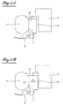
figure 1 est une vue en perspective partiellement coupée d'un réservoir de type bi-fonction, selon l'art antérieur, - la
figure 2 est une vue du réservoir de lafigure 1 , selon un angle de vue différent, - la
figure 3 est une vue de détail du réservoir desfigures 1 et 2 montrant en particulier le tube de régulation pour le pompage du liquide le plus chaud, - les
figures 4A et 4B sont des schémas illustrant une première solution pour accélérer le chauffage du liquide de lavage, selon la présente invention, après le démarrage du moteur (figure 4A ) et pendant le roulage du véhicule (figure 4B ), respectivement, - les
figures 5A et 5B sont des schémas illustrant un mode de réalisation du tube de régulation du réservoir pour la mise en oeuvre de la solution illustrée par lesfigures 4A et 4B , - les
figures 6A et 6B sont des schémas illustrant un mode de réalisation de la chambre de chauffage du réservoir pour la mise en oeuvre d'une deuxième solution pour accélérer le chauffage du liquide lave-glace, selon la présente invention, après le démarrage du moteur (figure 6A ) et pendant le roulage du véhicule (figure 6B ), respectivement, - les
figures 7A et 7B sont des schémas illustrant une variante de réalisation de la solution desfigures 6A et 6B , et - les
figures 8A et 8B sont des schémas illustrant une autre variante de réalisation de la solution desfigures 6A et 6B .
- the
figure 1 is a partially cutaway perspective view of a bi-function type reservoir, according to the prior art, - the
figure 2 is a view of the reservoir of thefigure 1 according to a different angle of view, - the
figure 3 is a detailed view of the reservoir ofFigures 1 and 2 showing in particular the control tube for pumping the hottest liquid, - the
Figures 4A and 4B are diagrams illustrating a first solution for accelerating the heating of the washing liquid, according to the present invention, after starting the engine (Figure 4A ) and while driving the vehicle (Figure 4B ), respectively, - the
Figures 5A and 5B are diagrams illustrating an embodiment of the tank control tube for the implementation of the solution illustrated by theFigures 4A and 4B , - the
Figures 6A and 6B are diagrams illustrating an embodiment of the reservoir heating chamber for the implementation of a second solution for accelerating the heating of the windshield washer fluid, according to the present invention, after starting the engine (Figure 6A ) and while driving the vehicle (Figure 6B ), respectively, - the
Figures 7A and 7B are diagrams illustrating an alternative embodiment of the solution of theFigures 6A and 6B , and - the
Figures 8A and 8B are diagrams illustrating another alternative embodiment of the solution of theFigures 6A and 6B .
En référence aux
Une chambre de chauffage 4, de faible volume, qui est en contact avec la boîte de dégazage 3 relativement chaude, monte rapidement en température, en particulier la zone la plus haute de cette chambre 4 du fait d'un échange de chaleur par convection.A
La chambre de réserve de liquide de lavage 2, qui contient la majeure partie du liquide de lavage des vitres ou des projecteurs, est thermiquement isolée de la boîte de dégazage 3 et de la chambre de chauffage 4 par une lame d'air 6 afin de na pas pomper de calories.The washing
En référence également au dessin de la
La hauteur du tube de régulation 7. conditionne la température du liquide de lavage aspiré par la pompe 8, le liquide chaud se trouvant en haut de la chambre de chauffage 4, tandis que le liquide dans la zone basse de la chambre est plus froid.The height of the
Des orifices calibrés permettent de mettre en relation les différents compartiments du réservoir ; ainsi, un orifice 9 permet le pompage du liquide chaud lorsque le niveau est faible et un orifice 10 permet le remplissage de la chambre de chauffage 4.Calibrated orifices make it possible to connect the different compartments of the tank; thus, an
Selon le principe de la présente invention, il est prévu un moyen permettant d'optimiser le fonctionnement du réservoir, notamment le chauffage du liquide de lavage lorsque le liquide de refroidissement contenu dans la boîte de dégazage 3 n'a pas encore atteint sa température optimale de fonctionnement.According to the principle of the present invention, there is provided a means for optimizing the operation of the reservoir, in particular the heating of the washing liquid when the coolant contained in the
Ce moyen de l'invention permet le chauffage rapide d'une petite partie de liquide de lavage qui sera ensuite pompé.This means of the invention allows the rapid heating of a small portion of washing liquid which will then be pumped.
On a représenté, sur les
On notera qu'il existe un gradient de température dans la chambre de chauffage 4, le liquide de lavage étant plus chaud dans la partie haute et étant plus froid dans la partie basse de ladite chambre 4.Note that there is a temperature gradient in the
Selon le principe de la présente invention, pour accélérer le chauffage du liquide aspiré immédiatement après le démarrage du véhicule, on pompe le liquide le plus chaud de la chambre de chauffage 4, par conséquent le liquide situé dans la partie haute de celle-ci. Une telle action sélective est possible en allongeant le tube de régulation 7 (
Selon un mode de réalisation illustré sur les
Le tube de régulation 17 des
Le fonctionnement du tube de régulation 17 est le suivait :
- La densité du liquide de lavage varie, comme la densité de tout liquide, en fonction de la température : elle diminue lorsque la température augmente et augmente lorsque la température diminue. Lorsque le liquide est relativement froid, le tube supérieur 22 est adapté pour venir flotter en partie haute, comme représenté schématiquement sur la
figure 5A .Le tube supérieur 22 est en extension hors du tube inférieur 21 et l'ensemble forme un tube de régulation de longueur maximale LM.
- The density of the washing liquid varies, like the density of any liquid, as a function of the temperature: it decreases when the temperature increases and increases when the temperature decreases. When the liquid is relatively cold, the
upper tube 22 is adapted to float in the upper part, as shown schematically on theFigure 5A . Theupper tube 22 is extended out of thelower tube 21 and the assembly forms a regulation tube of maximum length L M.
Lorsque la température du liquide augmente, sa densité diminue, et le tube supérieur 22 vient s'enfoncer dans le tube inférieur 21, comme représenté schématiquement sur la
On a réussi, par conséquent, avec le tube de régulation 17 ainsi conçu, à pomper en priorité le liquide le plus chaud de la chambre de chauffage 4 juste après le démarrage du véhicule, et ensuite, lorsque le véhicule roule et le moteur est chaud, à pomper un liquide qui n'est pas le plus chaud de façon à éviter tout risque de brûlure.It has therefore been possible with the
Une autre solution pour accélérer le chauffage du liquide après le démarrage du véhicule consiste à réduire le volume de la chambre de chauffage. Cette solution repose sur le principe qu'en diminuant la quantité de liquide à chauffer, le chauffage est plus rapide. Par contre, une fois la température optimale atteinte, il faut augmenter le volume de la chambre de chauffage de manière à disposer d'une plus grande quantité de liquide chaud.Another solution for accelerating the heating of the liquid after starting the vehicle is to reduce the volume of the heating chamber. This solution is based on the principle that by decreasing the amount of liquid to be heated, heating is faster. On the other hand, once the optimum temperature is reached, it is necessary to increase the volume of the heating chamber so as to have a larger quantity of hot liquid.
Selon un mode de réalisation illustré sur les
Les éléments et composants des
La chambre de chauffage est désignée par la référence 34. Au moins une partie de cette chambre 34 est fabriquée dans un matériau à mémoire de forme et est représentée schématiquement sur les
Selon un autre mode de réalisation illustré sur les
Les éléments et composants des
La chambre de chauffage 44 comprend une cloison 45 qui est déplacée par translation selon la flèche F, de façon à agrandir son volume. Cette translation F s'exerce par l'augmentation de la pression P dans la boîte de dégazage 3 due à l'augmentation de la température dans cette dernière. L'augmentation de la pression P provoque le déplacement du (ou des) piston(s) (non représentés) selon le sens de la flèche F de la
Selon encore un autre mode de réalisation illustré sur les
Comme pour les modes de réalisation précédents, les éléments et composants des
La chambre de chauffage 54 est divisée en deux sous-chambres 56 et 57, qui communiquent entre elles par l'intermédiaire d'une double cloison 55. A l'intérieur de cette double cloison 55 est inséré une plaque 58 en matériau de type paraffine. Ce matériau de type paraffine présente la propriété d'isoler thermiquement lorsqu'il est froid et de conduire la chaleur lorsqu'il est chaud.The
Lorsque la température dans la boîte de dégazage 3 est tiède, juste après le démarrage du véhicule, comme représenté sur le schéma de la
Une fois la boîte de dégazage 3 à bonne température, pendant le roulage du véhicule, comme représenté sur le schéma de la
De cette manière, on obtient une variation du volume de liquide à chauffer, ce volume étant plus petit à froid (démarrage du véhicule) et plus grand à chaud (pendant le roulage).In this way, a change in the volume of liquid to be heated is obtained, this volume being smaller when cold (starting the vehicle) and larger when the vehicle is hot (while driving).
Il importe de noter que, selon d'autres variantes de réalisation de l'invention, le compartiment faisant fonction de réserve de liquide 2 peut être dissocié de l'ensemble constitué par la chambre de chauffage (24 ; 34 ; 44 ou 54 selon les modes de réalisation) et le compartiment de boîte de dégazage 3. Pour des raisons d'encombrement, le compartiment faisant fonction de réserve de liquide 2 pourrait alors se trouver à un autre endroit du compartiment moteur ou dans une autre zone du véhicule.It should be noted that, according to other embodiments of the invention, the compartment serving as
Les différentes solutions, qui sont décrites ci-dessus à titre d'exemples non limitatifs de l'objet et de la portée de l'invention, présentent de nombreux avantages, parmi lesquels les avantages suivants :
- elles apportent au réservoir bi-fonction un fonctionnement optimal, permettant notamment le chauffage rapide de liquide de lavage au démarrage du véhicule lorsque le liquide de refroidissement contenu dans la boîte de dégazage n'a pas encore atteint sa température optimale de fonctionnement,
- elles permettent un fonctionnement du réservoir qui n'occasionne pas de perturbation dans la montée rapide en température de la boîte de dégazage après le démarrage du véhicule, cette montée étant nécessaire au bon fonctionnement du moteur,
- elles sont de conception, de fabrication et de fonctionnement simple et, de plus, elles sont des solutions fiables et économiques.
- they provide the bi-function tank with optimal operation, in particular allowing rapid heating of the washing liquid at the start of the vehicle when the coolant contained in the degassing box has not yet reached its optimum operating temperature,
- they allow operation of the tank which does not cause disturbance in the rapid rise in temperature of the degassing box after starting the vehicle, this rise being necessary for the proper functioning of the engine,
- they are simple in design, manufacture and operation and, moreover, they are reliable and economical solutions.
Bien entendu, la présente invention n'est pas limitée aux modes de réalisation décrits et représentés ci-dessus à titre d'exemples ; d'autres modes de réalisation peuvent être conçus par l'homme de métier sans sortir du cadre et de la portée de la présente invention.Of course, the present invention is not limited to the embodiments described and represented above by way of examples; other embodiments may be devised by those skilled in the art without departing from the scope and scope of the present invention.
Claims (14)
- A washing liquid reservoir, in particular for windows or headlamps of a motor vehicle, the reservoir comprising a compartment having the function of a degassing box (3) of the cooling circuit of the engine, a heating chamber (24; 34; 44; 54) in contact with the said degassing box compartment (3) and a compartment having the function of a washing liquid reserve (2), isolated from the degassing box compartment (3) and from the heating chamber (24; 34; 44; 54), characterized in that the said reservoir comprises, in addition, a means for accelerating the heating of a portion of the washing liquid when the cooling liquid contained in the degassing box (3) has not yet reached its optimum operating temperature, by permitting the rapid heating of a small portion of liquid contained in the heating chamber (24; 34; 44; 54) before being pumped.
- The reservoir according to Claim 1, characterized in that the said means for accelerating the heating of a portion of the washing liquid when the cooling liquid contained in the degassing box (3) has not yet reached its optimum operating temperature is constituted by a regulation tube (17), of variable length ("L"), placed in the heating chamber (24), which regulation tube (17) comes to lengthen and to pump the warmest liquid situated in the upper part of the said heating chamber (24).
- The reservoir according to Claim 2, characterized in that the said regulation tube (17) is formed by at least two parts : a lower tube (21) and an upper tube (22) being able to be displaced by translation inside the lower tube (21), and in that floats (23) are fixed to the upper part of the said upper tube (22), so as to obtain the density which allows the upper tube (22) to be caused to slide inside the lower tube (21) when the temperature of the liquid increases, and to thus obtain a regulation tube (17) of smaller length.
- The reservoir according to Claim 3, characterized in that the said upper tube (22) is itself composed of several sections of tube each having the function of upper tube which is movable under the effect of the change of density of the liquid, so as to adapt to the geometry of the reservoir.
- The reservoir according to Claim 1, characterized in that the said means for accelerating the heating of a portion of the washing liquid when the cooling liquid contained in the degassing box (3) has not yet reached its optimum operating temperature is constituted by a means for reduction of the volume of the heating chamber (34; 44; 54), so as to have less liquid to heat.
- The reservoir according to Claim 5, characterized in that the said means for reduction of the volume of the heating chamber (34) is constituted by at least a portion of the heating chamber, which is manufactured from a shape memory material, the geometry of the said shape memory part varying when the temperature of the liquid exceeds a predetermined threshold.
- The reservoir according to Claim 6, characterized in that the said portion of the heating chamber (34), which is manufactured from a shape memory material, is a partition (35) of the said heating chamber (34), the said partition (35) being of concave shape when the cooling liquid contained in the degassing box (3) has not yet reached its optimum operating temperature, and assuming a convex shape when the said liquid reaches its optimum operating temperature.
- The reservoir according to Claim 5, characterized in that the said means for reduction of the volume of the heating chamber (44) is constituted by a movable partition (45), which is displaced by translation under the effect of the increase in pressure in the degassing box (3) when the latter rises in temperature.
- The reservoir according to Claim 8, characterized in that the said movable partition (45) moves under the action of at least one piston.
- The reservoir according to Claim 5, characterized in that the said means for reduction of the volume of the heating chamber (54) is constituted by the fact that the said heating chamber (54) is divided into two sub-chambers (56, 57) which communicate with each other by means of an intermediate partition (55) comprising a material which thermally insulates the sub-chambers (56, 57) one with respect to the other when the cooling liquid contained in the degassing box (3) has not yet reached its optimum operating temperature and which conducts the heat when the said liquid has reached its optimum operating temperature.
- The reservoir according to Claim 10, characterized in that the said material of the intermediate partition (55) is a material of the paraffin type.
- The reservoir according to Claims 10 and 11, characterized in that the said intermediate partition (55) is a double partition and in that the said material of the intermediate partition (55) is a material in the form of a plate inserted into the interior of the double partition.
- A system for distribution of washing liquid, in particular of windows or headlamps, of a motor vehicle, characterized in that the reservoir compacts the reserve of washing liquid and the degassing box of the cooling circuit of the engine and in that the said reservoir is a reservoir in accordance with any one of Claims 1 to 12.
- A motor vehicle, characterized in that it comprises a system for distribution of washing liquid, in particular for washing windows or headlamps, in accordance with the distribution system of Claim 13.
Applications Claiming Priority (1)
| Application Number | Priority Date | Filing Date | Title |
|---|---|---|---|
| FR0858449A FR2939387B1 (en) | 2008-12-10 | 2008-12-10 | WASTE LIQUID TANK, ESPECIALLY WINDOWS OR HEADLAMPS, FOR A MOTOR VEHICLE |
Publications (2)
| Publication Number | Publication Date |
|---|---|
| EP2196367A1 EP2196367A1 (en) | 2010-06-16 |
| EP2196367B1 true EP2196367B1 (en) | 2012-02-08 |
Family
ID=40800163
Family Applications (1)
| Application Number | Title | Priority Date | Filing Date |
|---|---|---|---|
| EP09178728A Not-in-force EP2196367B1 (en) | 2008-12-10 | 2009-12-10 | Washing liquid tank, in particular for windows or projectors of a vehicle |
Country Status (3)
| Country | Link |
|---|---|
| EP (1) | EP2196367B1 (en) |
| AT (1) | ATE544643T1 (en) |
| FR (1) | FR2939387B1 (en) |
Cited By (1)
| Publication number | Priority date | Publication date | Assignee | Title |
|---|---|---|---|---|
| CN105247182A (en) * | 2012-09-06 | 2016-01-13 | 大陆汽车有限公司 | Plastic tank for an operating fluid |
Families Citing this family (3)
| Publication number | Priority date | Publication date | Assignee | Title |
|---|---|---|---|---|
| FR3002901B1 (en) * | 2013-03-06 | 2015-02-27 | Peugeot Citroen Automobiles Sa | WASHER FLUID LIQUID REFUELING DEVICE OF A VARIABLE VOLUME ADDITIONAL TANK OF A VEHICLE |
| FR3011212B1 (en) * | 2013-09-27 | 2015-10-23 | Peugeot Citroen Automobiles Sa | DEVICE FOR ADJUSTING THE TEMPERATURE OF A WINDSCREEN LIQUID OF AN ADDITIONAL RESEVOIR OF A VEHICLE |
| EP3715192A1 (en) * | 2019-03-26 | 2020-09-30 | Ningbo Geely Automobile Research & Development Co. Ltd. | A washer fluid arrangement |
Family Cites Families (4)
| Publication number | Priority date | Publication date | Assignee | Title |
|---|---|---|---|---|
| US4090668A (en) * | 1976-12-06 | 1978-05-23 | Kochenour Paul R | Windshield washer and deicer |
| GB9221323D0 (en) * | 1992-10-10 | 1992-11-25 | Mackay Robert | Hot screen wash conversion |
| FR2875763B1 (en) * | 2004-09-30 | 2006-12-22 | Peugeot Citroen Automobiles Sa | WATER HEATING DEVICE FOR WINDSCREEN WASHERS IN A MOTOR VEHICLE |
| FR2884477B1 (en) * | 2005-04-14 | 2008-12-19 | Coutier Moulage Gen Ind | RESERVOIR COMPRISING HEATING MEANS FOR A SPRAYING WASHING LIQUID ON GLASSES OR SPOTLIGHTS OF A MOTOR VEHICLE |
-
2008
- 2008-12-10 FR FR0858449A patent/FR2939387B1/en not_active Expired - Fee Related
-
2009
- 2009-12-10 EP EP09178728A patent/EP2196367B1/en not_active Not-in-force
- 2009-12-10 AT AT09178728T patent/ATE544643T1/en active
Cited By (2)
| Publication number | Priority date | Publication date | Assignee | Title |
|---|---|---|---|---|
| CN105247182A (en) * | 2012-09-06 | 2016-01-13 | 大陆汽车有限公司 | Plastic tank for an operating fluid |
| CN105247182B (en) * | 2012-09-06 | 2021-09-24 | 大陆汽车有限公司 | Plastic tank for working fluid |
Also Published As
| Publication number | Publication date |
|---|---|
| EP2196367A1 (en) | 2010-06-16 |
| FR2939387B1 (en) | 2011-01-14 |
| FR2939387A1 (en) | 2010-06-11 |
| ATE544643T1 (en) | 2012-02-15 |
Similar Documents
| Publication | Publication Date | Title |
|---|---|---|
| EP2196367B1 (en) | Washing liquid tank, in particular for windows or projectors of a vehicle | |
| EP2956729B1 (en) | Heat transport device with diphasic fluid | |
| EP2931093B1 (en) | Boiler for a machine for preparing beverages | |
| EP1794041B1 (en) | Device for reheating the water of the windscreen washers of a motor vehicle | |
| FR2893398A1 (en) | COLD STORAGE TANK UNIT AND REFRIGERATION CYCLE DEVICE USING THE SAME | |
| EP2181301B1 (en) | Thermal regulation passive device with fluid micro loop and capillary pumping | |
| EP1164341B1 (en) | Self-cooled beverage packing | |
| FR2905737A1 (en) | Internal combustion engine preheating method for motor vehicle, involves filling coolant in cooling circuit and radiators before cold starting of engine, where coolant from circuit is degassed before being sent to circuit`s remaining parts | |
| EP2164728B1 (en) | Method for producing a container for liquid used to wash the glass surfaces of a motor vehicle and resulting container | |
| FR2913374A1 (en) | COOLING CIRCUIT FOR A MOTOR VEHICLE, DEGASSING TANK AND MOTOR VEHICLE THEREFOR | |
| FR2884477A1 (en) | Cleaning liquid reservoir for e.g. window, of motor vehicle, has baffle to separate reservoir into two compartments and includes double wall, where reservoir surrounds expansion tank majorly and tank is disposed in one compartment | |
| EP1290387B1 (en) | Method for making a self-refrigerating drink package and equipment therefor | |
| EP2162323B1 (en) | Washing liquid tank for automobile | |
| FR2899185A1 (en) | Front windscreen/rear window washer`s water reheating device for motor vehicle, has double-walled sealed hollow body placed under vacuum for constituting closed thermal insulating screen between degassing tank and wall | |
| EP2176101B1 (en) | Set for reheating washing water for glass surfaces of a motor vehicle | |
| FR2923261A1 (en) | Expansion tank for cooling circuit of vehicle's internal combustion engine, has container including chamber provided with parts that contain liquid and air, respectively, and other chamber that receives pressurization unit pressurizing air | |
| EP2219909B1 (en) | Washing liquid tank for motor vehicle | |
| EP1909023B1 (en) | Process and device for storing cryogen fluid | |
| FR2985483A1 (en) | Washing liquid container for use in washing device for washing e.g. glass pane in car, has movable obturation element arranged between open position and partially closed position of channel according to temperature of liquid in channel | |
| FR2947502A1 (en) | Washing liquid tank for washing e.g. window pane in motor vehicle, has mixing chamber in direct communication with hot chamber and cold chamber, and closing device for closing communication of mixing chamber with cold and hot chambers | |
| EP1584876B1 (en) | Food serving trolley carrying a double amount of cooling material | |
| EP2213858B1 (en) | Device for heating the windscreen-washer liquid of an automobile | |
| EP2058612A1 (en) | Water supply to a water dispenser installed in the door of a refrigerator appliance | |
| FR2918624A1 (en) | Washing water reservoir for e.g. head light, of motor vehicle, has main and auxiliary chambers communicated with each other via air passage formed by channel associated to obstruction unit to exhaust air container in auxiliary chamber | |
| FR2971982A1 (en) | Bearing for windscreen wiper mechanism utilized for wiping windscreen of car, has grooves extending longitudinally along entire length of boring and extending to lower face of bearing to form openings for evacuation of water in boring |
Legal Events
| Date | Code | Title | Description |
|---|---|---|---|
| PUAI | Public reference made under article 153(3) epc to a published international application that has entered the european phase |
Free format text: ORIGINAL CODE: 0009012 |
|
| AK | Designated contracting states |
Kind code of ref document: A1 Designated state(s): AT BE BG CH CY CZ DE DK EE ES FI FR GB GR HR HU IE IS IT LI LT LU LV MC MK MT NL NO PL PT RO SE SI SK SM TR |
|
| AX | Request for extension of the european patent |
Extension state: AL BA RS |
|
| 17P | Request for examination filed |
Effective date: 20101210 |
|
| RIC1 | Information provided on ipc code assigned before grant |
Ipc: B60S 1/48 20060101AFI20110630BHEP Ipc: F01P 3/10 20060101ALI20110630BHEP Ipc: B60S 1/50 20060101ALI20110630BHEP |
|
| GRAP | Despatch of communication of intention to grant a patent |
Free format text: ORIGINAL CODE: EPIDOSNIGR1 |
|
| GRAS | Grant fee paid |
Free format text: ORIGINAL CODE: EPIDOSNIGR3 |
|
| GRAA | (expected) grant |
Free format text: ORIGINAL CODE: 0009210 |
|
| AK | Designated contracting states |
Kind code of ref document: B1 Designated state(s): AT BE BG CH CY CZ DE DK EE ES FI FR GB GR HR HU IE IS IT LI LT LU LV MC MK MT NL NO PL PT RO SE SI SK SM TR |
|
| REG | Reference to a national code |
Ref country code: GB Ref legal event code: FG4D Free format text: NOT ENGLISH |
|
| REG | Reference to a national code |
Ref country code: CH Ref legal event code: EP Ref country code: AT Ref legal event code: REF Ref document number: 544643 Country of ref document: AT Kind code of ref document: T Effective date: 20120215 |
|
| REG | Reference to a national code |
Ref country code: DE Ref legal event code: R096 Ref document number: 602009005187 Country of ref document: DE Effective date: 20120405 |
|
| REG | Reference to a national code |
Ref country code: NL Ref legal event code: VDEP Effective date: 20120208 |
|
| LTIE | Lt: invalidation of european patent or patent extension |
Effective date: 20120208 |
|
| REG | Reference to a national code |
Ref country code: GB Ref legal event code: 746 Effective date: 20120702 |
|
| PG25 | Lapsed in a contracting state [announced via postgrant information from national office to epo] |
Ref country code: NL Free format text: LAPSE BECAUSE OF FAILURE TO SUBMIT A TRANSLATION OF THE DESCRIPTION OR TO PAY THE FEE WITHIN THE PRESCRIBED TIME-LIMIT Effective date: 20120208 Ref country code: IS Free format text: LAPSE BECAUSE OF FAILURE TO SUBMIT A TRANSLATION OF THE DESCRIPTION OR TO PAY THE FEE WITHIN THE PRESCRIBED TIME-LIMIT Effective date: 20120608 Ref country code: LT Free format text: LAPSE BECAUSE OF FAILURE TO SUBMIT A TRANSLATION OF THE DESCRIPTION OR TO PAY THE FEE WITHIN THE PRESCRIBED TIME-LIMIT Effective date: 20120208 Ref country code: HR Free format text: LAPSE BECAUSE OF FAILURE TO SUBMIT A TRANSLATION OF THE DESCRIPTION OR TO PAY THE FEE WITHIN THE PRESCRIBED TIME-LIMIT Effective date: 20120208 Ref country code: NO Free format text: LAPSE BECAUSE OF FAILURE TO SUBMIT A TRANSLATION OF THE DESCRIPTION OR TO PAY THE FEE WITHIN THE PRESCRIBED TIME-LIMIT Effective date: 20120508 |
|
| REG | Reference to a national code |
Ref country code: DE Ref legal event code: R084 Ref document number: 602009005187 Country of ref document: DE Effective date: 20120619 |
|
| REG | Reference to a national code |
Ref country code: IE Ref legal event code: FD4D |
|
| PG25 | Lapsed in a contracting state [announced via postgrant information from national office to epo] |
Ref country code: PL Free format text: LAPSE BECAUSE OF FAILURE TO SUBMIT A TRANSLATION OF THE DESCRIPTION OR TO PAY THE FEE WITHIN THE PRESCRIBED TIME-LIMIT Effective date: 20120208 Ref country code: GR Free format text: LAPSE BECAUSE OF FAILURE TO SUBMIT A TRANSLATION OF THE DESCRIPTION OR TO PAY THE FEE WITHIN THE PRESCRIBED TIME-LIMIT Effective date: 20120509 Ref country code: LV Free format text: LAPSE BECAUSE OF FAILURE TO SUBMIT A TRANSLATION OF THE DESCRIPTION OR TO PAY THE FEE WITHIN THE PRESCRIBED TIME-LIMIT Effective date: 20120208 Ref country code: FI Free format text: LAPSE BECAUSE OF FAILURE TO SUBMIT A TRANSLATION OF THE DESCRIPTION OR TO PAY THE FEE WITHIN THE PRESCRIBED TIME-LIMIT Effective date: 20120208 Ref country code: PT Free format text: LAPSE BECAUSE OF FAILURE TO SUBMIT A TRANSLATION OF THE DESCRIPTION OR TO PAY THE FEE WITHIN THE PRESCRIBED TIME-LIMIT Effective date: 20120608 |
|
| REG | Reference to a national code |
Ref country code: AT Ref legal event code: MK05 Ref document number: 544643 Country of ref document: AT Kind code of ref document: T Effective date: 20120208 |
|
| PG25 | Lapsed in a contracting state [announced via postgrant information from national office to epo] |
Ref country code: CY Free format text: LAPSE BECAUSE OF FAILURE TO SUBMIT A TRANSLATION OF THE DESCRIPTION OR TO PAY THE FEE WITHIN THE PRESCRIBED TIME-LIMIT Effective date: 20120208 |
|
| PG25 | Lapsed in a contracting state [announced via postgrant information from national office to epo] |
Ref country code: DK Free format text: LAPSE BECAUSE OF FAILURE TO SUBMIT A TRANSLATION OF THE DESCRIPTION OR TO PAY THE FEE WITHIN THE PRESCRIBED TIME-LIMIT Effective date: 20120208 Ref country code: IE Free format text: LAPSE BECAUSE OF FAILURE TO SUBMIT A TRANSLATION OF THE DESCRIPTION OR TO PAY THE FEE WITHIN THE PRESCRIBED TIME-LIMIT Effective date: 20120208 Ref country code: RO Free format text: LAPSE BECAUSE OF FAILURE TO SUBMIT A TRANSLATION OF THE DESCRIPTION OR TO PAY THE FEE WITHIN THE PRESCRIBED TIME-LIMIT Effective date: 20120208 Ref country code: SI Free format text: LAPSE BECAUSE OF FAILURE TO SUBMIT A TRANSLATION OF THE DESCRIPTION OR TO PAY THE FEE WITHIN THE PRESCRIBED TIME-LIMIT Effective date: 20120208 Ref country code: CZ Free format text: LAPSE BECAUSE OF FAILURE TO SUBMIT A TRANSLATION OF THE DESCRIPTION OR TO PAY THE FEE WITHIN THE PRESCRIBED TIME-LIMIT Effective date: 20120208 Ref country code: SE Free format text: LAPSE BECAUSE OF FAILURE TO SUBMIT A TRANSLATION OF THE DESCRIPTION OR TO PAY THE FEE WITHIN THE PRESCRIBED TIME-LIMIT Effective date: 20120208 Ref country code: EE Free format text: LAPSE BECAUSE OF FAILURE TO SUBMIT A TRANSLATION OF THE DESCRIPTION OR TO PAY THE FEE WITHIN THE PRESCRIBED TIME-LIMIT Effective date: 20120208 |
|
| PG25 | Lapsed in a contracting state [announced via postgrant information from national office to epo] |
Ref country code: IT Free format text: LAPSE BECAUSE OF FAILURE TO SUBMIT A TRANSLATION OF THE DESCRIPTION OR TO PAY THE FEE WITHIN THE PRESCRIBED TIME-LIMIT Effective date: 20120208 Ref country code: SK Free format text: LAPSE BECAUSE OF FAILURE TO SUBMIT A TRANSLATION OF THE DESCRIPTION OR TO PAY THE FEE WITHIN THE PRESCRIBED TIME-LIMIT Effective date: 20120208 |
|
| PLBE | No opposition filed within time limit |
Free format text: ORIGINAL CODE: 0009261 |
|
| STAA | Information on the status of an ep patent application or granted ep patent |
Free format text: STATUS: NO OPPOSITION FILED WITHIN TIME LIMIT |
|
| 26N | No opposition filed |
Effective date: 20121109 |
|
| PG25 | Lapsed in a contracting state [announced via postgrant information from national office to epo] |
Ref country code: AT Free format text: LAPSE BECAUSE OF FAILURE TO SUBMIT A TRANSLATION OF THE DESCRIPTION OR TO PAY THE FEE WITHIN THE PRESCRIBED TIME-LIMIT Effective date: 20120208 |
|
| REG | Reference to a national code |
Ref country code: DE Ref legal event code: R097 Ref document number: 602009005187 Country of ref document: DE Effective date: 20121109 |
|
| PG25 | Lapsed in a contracting state [announced via postgrant information from national office to epo] |
Ref country code: ES Free format text: LAPSE BECAUSE OF FAILURE TO SUBMIT A TRANSLATION OF THE DESCRIPTION OR TO PAY THE FEE WITHIN THE PRESCRIBED TIME-LIMIT Effective date: 20120519 |
|
| BERE | Be: lapsed |
Owner name: PEUGEOT CITROEN AUTOMOBILES SA Effective date: 20121231 |
|
| PG25 | Lapsed in a contracting state [announced via postgrant information from national office to epo] |
Ref country code: MC Free format text: LAPSE BECAUSE OF NON-PAYMENT OF DUE FEES Effective date: 20121231 Ref country code: BG Free format text: LAPSE BECAUSE OF FAILURE TO SUBMIT A TRANSLATION OF THE DESCRIPTION OR TO PAY THE FEE WITHIN THE PRESCRIBED TIME-LIMIT Effective date: 20120508 |
|
| PG25 | Lapsed in a contracting state [announced via postgrant information from national office to epo] |
Ref country code: BE Free format text: LAPSE BECAUSE OF NON-PAYMENT OF DUE FEES Effective date: 20121231 |
|
| PG25 | Lapsed in a contracting state [announced via postgrant information from national office to epo] |
Ref country code: MT Free format text: LAPSE BECAUSE OF FAILURE TO SUBMIT A TRANSLATION OF THE DESCRIPTION OR TO PAY THE FEE WITHIN THE PRESCRIBED TIME-LIMIT Effective date: 20120208 |
|
| PG25 | Lapsed in a contracting state [announced via postgrant information from national office to epo] |
Ref country code: TR Free format text: LAPSE BECAUSE OF FAILURE TO SUBMIT A TRANSLATION OF THE DESCRIPTION OR TO PAY THE FEE WITHIN THE PRESCRIBED TIME-LIMIT Effective date: 20120208 |
|
| PG25 | Lapsed in a contracting state [announced via postgrant information from national office to epo] |
Ref country code: SM Free format text: LAPSE BECAUSE OF FAILURE TO SUBMIT A TRANSLATION OF THE DESCRIPTION OR TO PAY THE FEE WITHIN THE PRESCRIBED TIME-LIMIT Effective date: 20120208 Ref country code: LU Free format text: LAPSE BECAUSE OF NON-PAYMENT OF DUE FEES Effective date: 20121210 |
|
| PG25 | Lapsed in a contracting state [announced via postgrant information from national office to epo] |
Ref country code: HU Free format text: LAPSE BECAUSE OF FAILURE TO SUBMIT A TRANSLATION OF THE DESCRIPTION OR TO PAY THE FEE WITHIN THE PRESCRIBED TIME-LIMIT Effective date: 20091210 |
|
| REG | Reference to a national code |
Ref country code: CH Ref legal event code: PL |
|
| PG25 | Lapsed in a contracting state [announced via postgrant information from national office to epo] |
Ref country code: LI Free format text: LAPSE BECAUSE OF NON-PAYMENT OF DUE FEES Effective date: 20131231 Ref country code: CH Free format text: LAPSE BECAUSE OF NON-PAYMENT OF DUE FEES Effective date: 20131231 |
|
| PGFP | Annual fee paid to national office [announced via postgrant information from national office to epo] |
Ref country code: GB Payment date: 20141126 Year of fee payment: 6 Ref country code: DE Payment date: 20141121 Year of fee payment: 6 |
|
| PG25 | Lapsed in a contracting state [announced via postgrant information from national office to epo] |
Ref country code: MK Free format text: LAPSE BECAUSE OF FAILURE TO SUBMIT A TRANSLATION OF THE DESCRIPTION OR TO PAY THE FEE WITHIN THE PRESCRIBED TIME-LIMIT Effective date: 20120208 |
|
| REG | Reference to a national code |
Ref country code: FR Ref legal event code: PLFP Year of fee payment: 7 |
|
| PGFP | Annual fee paid to national office [announced via postgrant information from national office to epo] |
Ref country code: FR Payment date: 20151123 Year of fee payment: 7 |
|
| REG | Reference to a national code |
Ref country code: DE Ref legal event code: R119 Ref document number: 602009005187 Country of ref document: DE |
|
| GBPC | Gb: european patent ceased through non-payment of renewal fee |
Effective date: 20151210 |
|
| PG25 | Lapsed in a contracting state [announced via postgrant information from national office to epo] |
Ref country code: GB Free format text: LAPSE BECAUSE OF NON-PAYMENT OF DUE FEES Effective date: 20151210 Ref country code: DE Free format text: LAPSE BECAUSE OF NON-PAYMENT OF DUE FEES Effective date: 20160701 |
|
| REG | Reference to a national code |
Ref country code: FR Ref legal event code: ST Effective date: 20170831 |
|
| PG25 | Lapsed in a contracting state [announced via postgrant information from national office to epo] |
Ref country code: FR Free format text: LAPSE BECAUSE OF NON-PAYMENT OF DUE FEES Effective date: 20170102 |