EP2196267A2 - Procédé de laquage de la surface tridimensionnelle d'un composant - Google Patents
Procédé de laquage de la surface tridimensionnelle d'un composant Download PDFInfo
- Publication number
- EP2196267A2 EP2196267A2 EP09013726A EP09013726A EP2196267A2 EP 2196267 A2 EP2196267 A2 EP 2196267A2 EP 09013726 A EP09013726 A EP 09013726A EP 09013726 A EP09013726 A EP 09013726A EP 2196267 A2 EP2196267 A2 EP 2196267A2
- Authority
- EP
- European Patent Office
- Prior art keywords
- component
- paint
- unit
- application
- control unit
- Prior art date
- Legal status (The legal status is an assumption and is not a legal conclusion. Google has not performed a legal analysis and makes no representation as to the accuracy of the status listed.)
- Withdrawn
Links
Images
Classifications
-
- B—PERFORMING OPERATIONS; TRANSPORTING
- B05—SPRAYING OR ATOMISING IN GENERAL; APPLYING FLUENT MATERIALS TO SURFACES, IN GENERAL
- B05B—SPRAYING APPARATUS; ATOMISING APPARATUS; NOZZLES
- B05B13/00—Machines or plants for applying liquids or other fluent materials to surfaces of objects or other work by spraying, not covered by groups B05B1/00 - B05B11/00
- B05B13/02—Means for supporting work; Arrangement or mounting of spray heads; Adaptation or arrangement of means for feeding work
- B05B13/04—Means for supporting work; Arrangement or mounting of spray heads; Adaptation or arrangement of means for feeding work the spray heads being moved during spraying operation
- B05B13/0447—Installation or apparatus for applying liquid or other fluent material to conveyed separate articles
- B05B13/0457—Installation or apparatus for applying liquid or other fluent material to conveyed separate articles specially designed for applying liquid or other fluent material to 3D-surfaces of the articles, e.g. by using several moving spray heads
-
- B—PERFORMING OPERATIONS; TRANSPORTING
- B05—SPRAYING OR ATOMISING IN GENERAL; APPLYING FLUENT MATERIALS TO SURFACES, IN GENERAL
- B05B—SPRAYING APPARATUS; ATOMISING APPARATUS; NOZZLES
- B05B1/00—Nozzles, spray heads or other outlets, with or without auxiliary devices such as valves, heating means
- B05B1/14—Nozzles, spray heads or other outlets, with or without auxiliary devices such as valves, heating means with multiple outlet openings; with strainers in or outside the outlet opening
-
- B—PERFORMING OPERATIONS; TRANSPORTING
- B05—SPRAYING OR ATOMISING IN GENERAL; APPLYING FLUENT MATERIALS TO SURFACES, IN GENERAL
- B05B—SPRAYING APPARATUS; ATOMISING APPARATUS; NOZZLES
- B05B12/00—Arrangements for controlling delivery; Arrangements for controlling the spray area
-
- B—PERFORMING OPERATIONS; TRANSPORTING
- B05—SPRAYING OR ATOMISING IN GENERAL; APPLYING FLUENT MATERIALS TO SURFACES, IN GENERAL
- B05B—SPRAYING APPARATUS; ATOMISING APPARATUS; NOZZLES
- B05B13/00—Machines or plants for applying liquids or other fluent materials to surfaces of objects or other work by spraying, not covered by groups B05B1/00 - B05B11/00
- B05B13/02—Means for supporting work; Arrangement or mounting of spray heads; Adaptation or arrangement of means for feeding work
- B05B13/04—Means for supporting work; Arrangement or mounting of spray heads; Adaptation or arrangement of means for feeding work the spray heads being moved during spraying operation
- B05B13/0431—Means for supporting work; Arrangement or mounting of spray heads; Adaptation or arrangement of means for feeding work the spray heads being moved during spraying operation with spray heads moved by robots or articulated arms, e.g. for applying liquid or other fluent material to 3D-surfaces
-
- B—PERFORMING OPERATIONS; TRANSPORTING
- B05—SPRAYING OR ATOMISING IN GENERAL; APPLYING FLUENT MATERIALS TO SURFACES, IN GENERAL
- B05D—PROCESSES FOR APPLYING FLUENT MATERIALS TO SURFACES, IN GENERAL
- B05D7/00—Processes, other than flocking, specially adapted for applying liquids or other fluent materials to particular surfaces or for applying particular liquids or other fluent materials
- B05D7/02—Processes, other than flocking, specially adapted for applying liquids or other fluent materials to particular surfaces or for applying particular liquids or other fluent materials to macromolecular substances, e.g. rubber
-
- B—PERFORMING OPERATIONS; TRANSPORTING
- B05—SPRAYING OR ATOMISING IN GENERAL; APPLYING FLUENT MATERIALS TO SURFACES, IN GENERAL
- B05D—PROCESSES FOR APPLYING FLUENT MATERIALS TO SURFACES, IN GENERAL
- B05D7/00—Processes, other than flocking, specially adapted for applying liquids or other fluent materials to particular surfaces or for applying particular liquids or other fluent materials
- B05D7/50—Multilayers
- B05D7/56—Three layers or more
- B05D7/57—Three layers or more the last layer being a clear coat
- B05D7/574—Three layers or more the last layer being a clear coat at least some layers being let to dry at least partially before applying the next layer
-
- B—PERFORMING OPERATIONS; TRANSPORTING
- B25—HAND TOOLS; PORTABLE POWER-DRIVEN TOOLS; MANIPULATORS
- B25J—MANIPULATORS; CHAMBERS PROVIDED WITH MANIPULATION DEVICES
- B25J11/00—Manipulators not otherwise provided for
- B25J11/0075—Manipulators for painting or coating
-
- B—PERFORMING OPERATIONS; TRANSPORTING
- B41—PRINTING; LINING MACHINES; TYPEWRITERS; STAMPS
- B41J—TYPEWRITERS; SELECTIVE PRINTING MECHANISMS, i.e. MECHANISMS PRINTING OTHERWISE THAN FROM A FORME; CORRECTION OF TYPOGRAPHICAL ERRORS
- B41J3/00—Typewriters or selective printing or marking mechanisms characterised by the purpose for which they are constructed
- B41J3/407—Typewriters or selective printing or marking mechanisms characterised by the purpose for which they are constructed for marking on special material
- B41J3/4073—Printing on three-dimensional objects not being in sheet or web form, e.g. spherical or cubic objects
-
- B—PERFORMING OPERATIONS; TRANSPORTING
- B05—SPRAYING OR ATOMISING IN GENERAL; APPLYING FLUENT MATERIALS TO SURFACES, IN GENERAL
- B05B—SPRAYING APPARATUS; ATOMISING APPARATUS; NOZZLES
- B05B12/00—Arrangements for controlling delivery; Arrangements for controlling the spray area
- B05B12/08—Arrangements for controlling delivery; Arrangements for controlling the spray area responsive to condition of liquid or other fluent material to be discharged, of ambient medium or of target ; responsive to condition of spray devices or of supply means, e.g. pipes, pumps or their drive means
- B05B12/12—Arrangements for controlling delivery; Arrangements for controlling the spray area responsive to condition of liquid or other fluent material to be discharged, of ambient medium or of target ; responsive to condition of spray devices or of supply means, e.g. pipes, pumps or their drive means responsive to conditions of ambient medium or target, e.g. humidity, temperature position or movement of the target relative to the spray apparatus
- B05B12/122—Arrangements for controlling delivery; Arrangements for controlling the spray area responsive to condition of liquid or other fluent material to be discharged, of ambient medium or of target ; responsive to condition of spray devices or of supply means, e.g. pipes, pumps or their drive means responsive to conditions of ambient medium or target, e.g. humidity, temperature position or movement of the target relative to the spray apparatus responsive to presence or shape of target
-
- B—PERFORMING OPERATIONS; TRANSPORTING
- B05—SPRAYING OR ATOMISING IN GENERAL; APPLYING FLUENT MATERIALS TO SURFACES, IN GENERAL
- B05D—PROCESSES FOR APPLYING FLUENT MATERIALS TO SURFACES, IN GENERAL
- B05D3/00—Pretreatment of surfaces to which liquids or other fluent materials are to be applied; After-treatment of applied coatings, e.g. intermediate treating of an applied coating preparatory to subsequent applications of liquids or other fluent materials
- B05D3/06—Pretreatment of surfaces to which liquids or other fluent materials are to be applied; After-treatment of applied coatings, e.g. intermediate treating of an applied coating preparatory to subsequent applications of liquids or other fluent materials by exposure to radiation
- B05D3/061—Pretreatment of surfaces to which liquids or other fluent materials are to be applied; After-treatment of applied coatings, e.g. intermediate treating of an applied coating preparatory to subsequent applications of liquids or other fluent materials by exposure to radiation using U.V.
- B05D3/065—After-treatment
- B05D3/067—Curing or cross-linking the coating
-
- B—PERFORMING OPERATIONS; TRANSPORTING
- B05—SPRAYING OR ATOMISING IN GENERAL; APPLYING FLUENT MATERIALS TO SURFACES, IN GENERAL
- B05D—PROCESSES FOR APPLYING FLUENT MATERIALS TO SURFACES, IN GENERAL
- B05D3/00—Pretreatment of surfaces to which liquids or other fluent materials are to be applied; After-treatment of applied coatings, e.g. intermediate treating of an applied coating preparatory to subsequent applications of liquids or other fluent materials
- B05D3/08—Pretreatment of surfaces to which liquids or other fluent materials are to be applied; After-treatment of applied coatings, e.g. intermediate treating of an applied coating preparatory to subsequent applications of liquids or other fluent materials by flames
Definitions
- the present invention relates to a method for painting a three-dimensional surface of a component, in particular a vehicle plastic component.
- the painting of the three-dimensional surfaces of components is usually carried out by means of automatic painting guns and / or Hochrotationszerstäubern with and without electrostatics, in which case in particular, for example. also hydro and solvent based paints are applied.
- the applied atomizer technology is based essentially on two principles of action, including air atomization and rotary atomization, wherein by means of air atomization or rotary atomization the paint material to be applied is very finely atomized and not the entire droplets reach the component, along with a corresponding loss of material that is no longer usable is or is expensive to recycle.
- the order efficiency in these known methods is only about 50% to 70%.
- the present invention is therefore based on the object of specifying a method for painting a three-dimensional surface of a component, which can be significantly reduced or almost completely avoided in comparison to known solutions of the resulting during the painting process loss of Lackiermaterial or paint.
- This object is achieved with a method for painting a three-dimensional surface of a component, in particular a vehicle plastic component, wherein on the surface by means of at least one digitally controllable painting a paint is applied, wherein the painting device at least one spaced from the surface application unit, in particular one Printhead, for applying the paint on the surface and at least one metering unit for adjusting the exiting from the applicator unit paint volume flow, and wherein the applicator unit is moved during painting over the surface, and at least temporarily follows a three-dimensional trajectory.
- a movement of an application unit of a digitally controllable coating device, in particular of a print head takes place, whereby the application unit is moved over the surface during painting, and at least temporarily follows a three-dimensional trajectory.
- the trajectory is a function of the geometry of the surface or a function of the shape of the surface, so that the application unit performs a defined during movement in relation to the surface movement, accompanied by a significant reduction or almost complete avoidance of the loss of paint or painting material during painting.
- the costs for paint removal (overspray), the costs for paint disposal, the costs for supply air treatment, the costs for exhaust air treatment and the costs for masking in the case of partial paint coating are thus eliminated or reduced in particular.
- the digitally controllable painting device is preferably designed in the form of a digitally controllable printing device which is set up to apply paint in accordance with a known digital printing method.
- Digital printing is understood to mean a printing process in which the printed image is transferred directly from a computer to a printing press without the use of a static printing form.
- a typical digital printing process is the known inkjet printing process.
- the print head or the application unit is preferably designed in the form of a print head for an inkjet printer or essentially in the form of a print head for an inkjet printer, and therefore has at least one nozzle, preferably a plurality of nozzles in the form of tubes or needles. which spray paint or paint on the surface of the component in a known manner for painting or painting.
- a trained in the form of a printhead for an inkjet printer printhead allows a finely distributed application of the paint on the surface of the component.
- These printheads do not atomize the paint or varnish and thereby have a much higher application efficiency (AWG), which in conjunction with the defined movement along the trajectory according to the invention is accompanied by a very significant reduction in the loss of varnish or varnish during varnishing.
- the variable portioning of the individual drops may e.g. be controlled by heating elements in the pressure nozzles, or over the time of the applied electrical voltage to the piezoelectric crystals.
- the metering unit preferably has controllable gear pumps or diaphragm pumps in order to set the paint volume flow.
- the metering unit may have a metering cylinder with a piston received therein in a longitudinally movable manner in order to adjust the lacquer volume flow, that is to say the quantity of lacquer emerging from the applicator unit per unit time, wherein the metering unit can be actuated by means of a servomotor.
- the application units are preferably supplied individually with paint, wherein the metering and preferably also the material pre-pressure are adapted to the nozzle diameter of the application unit or application units and to the paint volume flow.
- an industrial robot is used to move the application unit, wherein the industrial robot for moving the application unit is controlled by a first control unit on which a robot program associated with the component runs, and wherein the metering unit for setting a predetermined paint volume flow is controlled by a second control unit on which a component associated dosing program runs.
- the first control unit is identical to the second control unit.
- the predetermined paint volume flow may preferably depend on the position of the application unit above the surface.
- an industrial robot which may be designed in particular in the form of a 6-axis industrial robot, according to the invention, the accessibility of difficult areas of the surface to be painted, such. Undercuts, guaranteed.
- a plurality of application units in particular at least two application units are provided according to the invention.
- the number of application units is dependent on the required area performance and in particular on the geometry of the surface to be coated and is selected accordingly.
- the application units are preferably arranged in rows, in particular next to one another or behind one another.
- the paint volume flows of the application units are preferably individually and independently of one another adjustable or controllable by the at least one metering unit.
- About axes of movement of the robot can be approached in all three spatial directions all positions above the surface to be painted by the application unit or theprocessungsin whatsoever.
- the predetermined paint volume flow can be a paint volume flow which is constant in time and therefore depend in particular only on the position of the application unit above the surface.
- the predetermined paint volume flow may also depend on the speed of the application unit moving it over the surface.
- the robot program associated with the component makes it possible to move the application unit or application units over the surface of the component specifically adapted to the component-which may be, in particular, a vehicle-plastic component.
- the entire sequence of movements, which at least at times comprises the movement along a three-dimensional trajectory is in particular a function of paint characteristics and / or a function of brush values and / or a function of paint layer thicknesses or paint layer thickness distributions to be achieved and / or a function the geometry of the surface of the component to be painted or a function of the shape of the surface of the component to be painted.
- the paint volume flow can also be a function of the paint characteristics and / or a function of brush values and / or a function of paint layer thicknesses or paint layer thickness distributions to be achieved and / or a function of the geometry of the surface to be painted of the component or a Function of the shape of the surface to be painted of the component.
- the required parameters are preferably stored via the robot program or the dosing program and preferably also via brush values.
- the distance of the applicator unit to the surface is measured with a distance measuring device, which may preferably be an infrared distance measuring device, wherein the measured distance is preferably used as an actual quantity for a distance-controlled movement of the applicator unit above the surface ,
- the application unit is moved substantially at a constant distance from the surface. This makes it possible to produce a very uniform paint layer thickness distribution over the surface.
- the trajectory is adapted to the geometry of the surface or adapted to the shape of the surface. This also makes it possible to produce a very uniform paint layer thickness distribution over the surface.
- the varnish used is a UV-curable clearcoat or a reactive varnish, such as e.g. a polyurethane or epoxy paint or a physically drying paint such as e.g. a dispersion.
- a reactive varnish such as e.g. a polyurethane or epoxy paint or a physically drying paint such as e.g. a dispersion.
- UV light-curing clearcoat to form a protective layer for the surface, such as in the form of a UV-curing "Clearcoats" is particularly in 3-dimensional vehicle plastic components, such as external attachments (eg plastic bumpers) in particular due to improved properties such as scratch resistance, chemical resistance, etc.
- vehicle plastic components with a UV-curing clearcoat is not yet economical due to the higher cost compared to PU clearcoat factor 2 to 3 costs.
- the paint used preferably has a solids content according to DIN EN ISO 3251 within a range of 20% to 60% for reactive polyurethane systems and 60% to 90% for UV light-curing clearcoats, and a dynamic viscosity at 23 ° C. according to DIN 53019 within a range of 100 to 500 mPas, preferably 100 to 400 mPas, particularly preferably 200 to 350 mPas.
- a varnish formed in accordance with the invention can flow through nozzles of the application unit without interference, along with a trouble-free varnishing process.
- a lacquer whose solids content and viscosity are selected or set in such a way that a lacquer drop emerging from a nozzle of the applicator unit and essentially applied to the surface retains its shape substantially.
- topographical effects in particular in the form of full-area or partial “scarring effects", can be achieved.
- an identification code of the component which is stored on an RFID transponder, which is arranged in the vicinity of the component or attached thereto, read from an RFID reader, and the identification code before applying the paint is supplied to a third control unit, which is set up, upon receipt of the identification code, to start the robot program associated with the component and the dosing program associated with the component.
- the third control unit is preferably identical to the first or the second control unit.
- RFID Radio Frequency Identification
- RFID is a technical system that provides the most convenient way to read data without having to touch or directly see that data because it is transmitted by radio.
- Known RFID systems consist mainly of an RFID transponder (also called RFID tags) and an RFID reader, wherein the RFID transponder contains important data on a chip, which it emits on stimulation from the outside, namely by the reader.
- RFID transponders can have dimensions of the order of a few millimeters, and can be conveniently attached to any objects.
- a robot program and metering program specially assigned to the respective component can be started by the third control unit in a practical manner. This is particularly advantageous in the production of a large number of components in order to avoid painting with a robot program or dosing program that is wrong or not intended for the component in question.
- the at least one application unit is movably held on the industrial robot, and by means of at least one digitally controllable adjustment device coupled to the application unit, the application unit is transferred into a predetermined position assigned to the component prior to application of the coating relative to the industrial robot and in this kept stationary.
- a positioning of the application units or of the application unit required for the respective robot program or metering program can be adjusted relative to the component, which can in particular be adapted to the geometry of the component or the geometry of the surface of the component to be painted.
- the adjustment can also take place via a once-fixed setting, or by exchanging or erecting the entire arrangement, which has at least one application unit.
- an identification code of the component which is stored on an RFID transponder, which is arranged in the vicinity of the component or attached thereto, is read out by an RFID reader, and the identification code is fed to an actuator control unit, which is set up, upon receipt of the identification code, to actuate the adjusting device in such a way that the applicator unit is transferred into the predetermined position assigned to the component and held stationary therein.
- the adjusting device control unit is preferably identical to the first or second control unit.
- the invention further relates to a system for painting a three-dimensional surface of a component, in particular a vehicle plastic component, with at least one digitally controllable painting device for applying paint to the surface of the component, wherein the painting device at least one application unit, in particular a print head for applying the Lacks on the surface and at least one metering unit for adjusting the exiting from the applicator unit paint volume flow, and at least one industrial robot on which the applicator unit is mounted, wherein the industrial robot is arranged, the applicator unit during the application of the paint, at least temporarily along a three-dimensional trajectory to move over the surface to be painted.
- the trajectory is arranged at a distance from the surface in order to avoid contact of the application unit with the surface.
- the system according to the invention is provided in particular for carrying out the method according to the invention for coating a three-dimensional surface of a component, in particular of a vehicle plastic component.
- the system comprises a first control unit, wherein the industrial robot for moving the applicator unit is controllable by the first control unit via a runnable on this robot program, which is a component associated robot program, and the system has a second control unit, wherein the metering unit for setting a predetermined paint volume flow of the second control unit via a drained on this dosing program is controlled, which is a component associated dosing program.
- the first control unit is identical to the second control unit.
- the predetermined paint volume flow preferably depends on the position of the application unit above the surface.
- the system has at least one RFID reader and one third control unit, wherein the RFID reader is provided for, before the application of the paint, an identification code of the component which is stored on an RFID transponder, which is in the vicinity the component is arranged or attached to the read, and to the third control unit, which is adapted to start on receipt of the identification code, the robot associated with the component program and the component associated dosing program.
- the third control unit is preferably identical to the first or the second control unit.
- the at least one application unit is movably held on the industrial robot, and the system has a digitally controllable adjustment device coupled to the application unit, which is set up to transfer the application unit into a predetermined position relative to the industrial robot and in this position to hold stationary relative to the industrial robot.
- the system preferably has at least one RFID reading device and one positioning device control unit, wherein the RFID reading device is provided for, before the application of the paint, an identification code of the component which is stored on an RFID transponder arranged in the vicinity of the component or attached thereto, read and supply to the adjusting device control unit, which is configured, upon receipt of the identification code, to control the adjusting device such that the applicator unit is transferred to a predetermined position assigned to the component and held stationary therein ,
- the actuator control unit is identical to the first or second control unit.
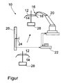
- FIGURE shows a system 10 according to the invention for painting a three-dimensional surface 12 of a vehicle plastic component 14 in the form of a bumper 14.
- the system 10 has a digitally controllable painting device 16 for applying paint to the surface 12 of the bumper 14.
- the painting device 16 has an application unit in the form of a digitally controllable print head 18 for applying the paint to the surface 12, and a metering unit (not shown) for adjusting the paint volume flow emerging from the print head 18.
- the system 10 further includes an industrial robot 20 to which the printhead 18 is mounted and a control unit 22 in the form of a computer.
- the system 12 may also include a plurality of digitally controllable painting devices 16 having a corresponding plurality of metering units and a plurality of print heads 18 mounted on the industrial robot 20, e.g. are arranged in series one behind the other or side by side.
- the industrial robot 20 can be controlled to move the print head 18 by the control unit 22 via a robot program that can be run on it, which is a robot program associated with the bumper 14.
- the metering unit is for setting a predetermined paint volume flow, which depends on the position of the print head 18 above the surface, controllable by the control unit 22 via a run on this metering program, which is a bumper 14 associated metering program.
- the system also includes an RFID reader 24 attached to a support frame 26.
- the RFID reader 24 is provided to read an identification code of the bumper 14 prior to applying the paint to the surface 12, which is stored on an RFID transponder, not shown, which is attached to the bumper 14, and the identification code of the control unit 22, which is configured, upon receipt of the identification code, to start the robot program and dosing program associated with the bumper 14.
- the bumper 14 is located on a goods carrier 28, which is movable by means of a conveying device, not shown, wherein the goods carrier 28 according to the invention is first passed past the RFID reader 24 to read the identification code. Subsequently, the movement (shown schematically by an arrow) of the goods carrier 28 with the arranged thereon bumper 14 in a painting position in the vicinity of the industrial robot 20, which performs the painting of the surface 12 of the bumper 14 according to the associated robot program and the associated dosing, wherein
- the identification code of the control unit 22 is supplied delayed to provide process time for the painting preceding the painting movement of the goods carrier 28 to the painting position.
- the cleaning of the printhead 18 and the printheads 18, respectively takes place via a separately stored rinse program initiated as required (e.g., production stoppages, end of production, contamination of the nozzles of the printhead 18 and the printheads 18, respectively) between the painting operations.
- a rinsing agent is supplied to the printheads 18 via paint-carrying channels.
- the industrial robot 20 moves to a preselected flushing position, where the discharged flushing residue is collected in containers and can be disposed of in a targeted manner.
- the lacquer to be applied to the surface can be, in particular, a clear lacquer curing by UV light (as ultraviolet light), which is applied to an already pretreated surface of the bumper during a partial process of a lacquering process described below in brief for painting a bumper (sub-process no ), wherein the bumper is a manufactured by an injection molding bumper.
- UV light as ultraviolet light
Applications Claiming Priority (1)
| Application Number | Priority Date | Filing Date | Title |
|---|---|---|---|
| DE102008061203A DE102008061203A1 (de) | 2008-12-09 | 2008-12-09 | Verfahren zum Lackieren einer dreidimensionalen Oberfläche eines Bauteils |
Publications (1)
| Publication Number | Publication Date |
|---|---|
| EP2196267A2 true EP2196267A2 (fr) | 2010-06-16 |
Family
ID=42026239
Family Applications (1)
| Application Number | Title | Priority Date | Filing Date |
|---|---|---|---|
| EP09013726A Withdrawn EP2196267A2 (fr) | 2008-12-09 | 2009-10-31 | Procédé de laquage de la surface tridimensionnelle d'un composant |
Country Status (2)
| Country | Link |
|---|---|
| EP (1) | EP2196267A2 (fr) |
| DE (1) | DE102008061203A1 (fr) |
Cited By (21)
| Publication number | Priority date | Publication date | Assignee | Title |
|---|---|---|---|---|
| TWI406775B (zh) * | 2011-09-30 | 2013-09-01 | Using UV Digital Inkjet Method to Make Stereo Image Method | |
| ITPI20120062A1 (it) * | 2012-05-21 | 2013-11-22 | Cmo Di Sodini Dino & C S N C | Metodo per la verniciatura di oggetti e apparecchiatura che attua tale metodo |
| FR3010918A1 (fr) * | 2013-09-23 | 2015-03-27 | Eads Europ Aeronautic Defence | Dispositif pour l'application de revetements projetes sur des pieces et procede associe |
| DE102014206697A1 (de) * | 2014-04-07 | 2015-10-08 | Homag Holzbearbeitungssysteme Gmbh | Vorrichtung sowie Verfahren zum Erstellen von Volumenkörpern |
| CN105793050A (zh) * | 2013-11-29 | 2016-07-20 | 株式会社日立产机系统 | 补给容器和包括该补给容器的喷墨记录装置 |
| WO2016142510A1 (fr) | 2015-03-11 | 2016-09-15 | Reydel Automotive B.V. | Procede et installation de revetement d'un corps avec formation d'une surface structuree |
| DE102015109420A1 (de) * | 2015-06-12 | 2016-12-15 | Special Coatings Gmbh & Co. Kg | Beschichtungsvorrichtung mit Zahnradpumpenförderung |
| CN107442318A (zh) * | 2017-07-30 | 2017-12-08 | 深圳市华成工业控制有限公司 | 一种基于rfid的自动喷涂系统及其喷涂方法 |
| DE102016014952A1 (de) * | 2016-12-14 | 2018-06-14 | Dürr Systems Ag | Beschichtungseinrichtung zur Beschichtung von Bauteilen |
| DE102016014944A1 (de) * | 2016-12-14 | 2018-06-14 | Dürr Systems Ag | Beschichtungsverfahren und entsprechende Beschichtungseinrichtung |
| WO2018108562A1 (fr) * | 2016-12-14 | 2018-06-21 | Dürr Systems Ag | Dispositif de revêtement et procédé de fonctionnement associé |
| RU2659039C1 (ru) * | 2015-07-01 | 2018-06-27 | Фольксваген Де Мехико, С.А. Де К.В. | Способ цифровой печати на кузове транспортного средства |
| WO2018142012A1 (fr) * | 2017-02-06 | 2018-08-09 | Maier, S. Coop. | Procédé de fabrication d'un enjoliveur à partie décorative imprimée pour véhicule, enjoliveur à partie décorative imprimée et système d'exécution dudit procédé |
| US11167308B2 (en) | 2016-12-14 | 2021-11-09 | Dürr Systems Ag | Print head for the application of a coating agent on a component |
| US11167302B2 (en) | 2016-12-14 | 2021-11-09 | Dürr Systems Ag | Coating device and associated operating method |
| US11167297B2 (en) | 2016-12-14 | 2021-11-09 | Dürr Systems Ag | Print head for the application of a coating agent |
| US11298717B2 (en) | 2016-12-14 | 2022-04-12 | Dürr Systems Ag | Print head having a temperature-control device |
| US11338312B2 (en) | 2016-12-14 | 2022-05-24 | Dürr Systems Ag | Print head and associated operating method |
| US11440035B2 (en) | 2016-12-14 | 2022-09-13 | Dürr Systems Ag | Application device and method for applying a multicomponent coating medium |
| US11504735B2 (en) | 2016-12-14 | 2022-11-22 | Dürr Systems Ag | Coating device having first and second printheads and corresponding coating process |
| US11975345B2 (en) | 2016-12-14 | 2024-05-07 | Dürr Systems Ag | Coating installation and corresponding coating method |
Families Citing this family (4)
| Publication number | Priority date | Publication date | Assignee | Title |
|---|---|---|---|---|
| DE102010004496B4 (de) | 2010-01-12 | 2020-06-18 | Hermann Müller | Verfahren zum Betrieb einer Vorrichtung zum Beschichten und/oder Bedrucken eines Werkstückes |
| DE102010038332B4 (de) | 2010-07-23 | 2018-03-08 | Kba-Metalprint Gmbh | Beschichtungsverfahren zumindest einer Seitenfläche eines tafelförmigen Gutes |
| DE102011120581A1 (de) * | 2011-12-07 | 2013-06-13 | Leopold Kostal Gmbh & Co. Kg | Verfahren zur Herstellung eines vorderseitig galvanisch beschichteten Bedien-, Dekor- oder Anzeigeelements mit nicht beschichteten Bereichen |
| DE102018202857A1 (de) * | 2018-02-26 | 2019-08-29 | MTU Aero Engines AG | Beschichtungsvorrichtung für Turbinen- oder Verdichterscheiben mit integral ausgebildeten Schaufeln |
Family Cites Families (5)
| Publication number | Priority date | Publication date | Assignee | Title |
|---|---|---|---|---|
| DE3737455A1 (de) * | 1986-11-06 | 1988-05-19 | Westinghouse Electric Corp | Einrichtung und verfahren zum erzeugen von farbmustern |
| DE102004044655B4 (de) * | 2004-09-15 | 2009-06-10 | Airbus Deutschland Gmbh | Lackier-Vorrichtung, Lackier-Anordnung, Verfahren zum Lackieren einer gekrümmten Oberfläche eines Flugzeugs und Verwendung einer Inkjet-Einrichtung zum Lackieren eines Flugzeugs |
| EP1954411B1 (fr) * | 2005-11-15 | 2013-02-20 | Akzo Nobel Coatings International BV | Procede de preparation destine a une feuille de revetement multicouche |
| EP1884365A1 (fr) * | 2006-07-28 | 2008-02-06 | Abb Research Ltd. | Applicateur de peinture et procédé de revêtement |
| DE112007003545A5 (de) * | 2007-04-16 | 2010-04-01 | Siemens Aktiengesellschaft | Datenübertragungssystem mit mobilen Funkteilnehmern, Verwendung eines derartigen Systems sowie Automatisierungssystem |
-
2008
- 2008-12-09 DE DE102008061203A patent/DE102008061203A1/de not_active Withdrawn
-
2009
- 2009-10-31 EP EP09013726A patent/EP2196267A2/fr not_active Withdrawn
Cited By (39)
| Publication number | Priority date | Publication date | Assignee | Title |
|---|---|---|---|---|
| TWI406775B (zh) * | 2011-09-30 | 2013-09-01 | Using UV Digital Inkjet Method to Make Stereo Image Method | |
| ITPI20120062A1 (it) * | 2012-05-21 | 2013-11-22 | Cmo Di Sodini Dino & C S N C | Metodo per la verniciatura di oggetti e apparecchiatura che attua tale metodo |
| WO2013175392A1 (fr) | 2012-05-21 | 2013-11-28 | Cmo Di Sodini Dino & C. S.N.C. | Procédé et appareil pour peindre des objets |
| CN104487174A (zh) * | 2012-05-21 | 2015-04-01 | Cmo索迪尼蒂诺和C.S.N.C.公司 | 将对象涂漆的方法和仪器 |
| US9827583B2 (en) | 2012-05-21 | 2017-11-28 | Cmo Di Sodini Dino & C. S.N.C. | Method and apparatus for painting objects |
| FR3010918A1 (fr) * | 2013-09-23 | 2015-03-27 | Eads Europ Aeronautic Defence | Dispositif pour l'application de revetements projetes sur des pieces et procede associe |
| CN105793050A (zh) * | 2013-11-29 | 2016-07-20 | 株式会社日立产机系统 | 补给容器和包括该补给容器的喷墨记录装置 |
| DE102014206697A1 (de) * | 2014-04-07 | 2015-10-08 | Homag Holzbearbeitungssysteme Gmbh | Vorrichtung sowie Verfahren zum Erstellen von Volumenkörpern |
| US10576729B2 (en) | 2014-04-07 | 2020-03-03 | Homag Gmbh | Device and method for producing three-dimensional objects |
| WO2016142510A1 (fr) | 2015-03-11 | 2016-09-15 | Reydel Automotive B.V. | Procede et installation de revetement d'un corps avec formation d'une surface structuree |
| US10857812B2 (en) | 2015-03-11 | 2020-12-08 | Reydel Automotive B.V. | Method and installation for coating a body with formation of a structured surface |
| DE102015109420A1 (de) * | 2015-06-12 | 2016-12-15 | Special Coatings Gmbh & Co. Kg | Beschichtungsvorrichtung mit Zahnradpumpenförderung |
| US10232636B2 (en) | 2015-07-01 | 2019-03-19 | Volkswagen De Mexico S.A. De C.V. | Digital printing process of a vehicle body |
| RU2659039C1 (ru) * | 2015-07-01 | 2018-06-27 | Фольксваген Де Мехико, С.А. Де К.В. | Способ цифровой печати на кузове транспортного средства |
| EP3718643B1 (fr) | 2016-12-14 | 2021-09-01 | Dürr Systems AG | Dispositif de revêtement destiné au revêtement de composants |
| DE102016014944A1 (de) * | 2016-12-14 | 2018-06-14 | Dürr Systems Ag | Beschichtungsverfahren und entsprechende Beschichtungseinrichtung |
| US11154892B2 (en) | 2016-12-14 | 2021-10-26 | Dürr Systems Ag | Coating device for applying coating agent in a controlled manner |
| US11975345B2 (en) | 2016-12-14 | 2024-05-07 | Dürr Systems Ag | Coating installation and corresponding coating method |
| US11167308B2 (en) | 2016-12-14 | 2021-11-09 | Dürr Systems Ag | Print head for the application of a coating agent on a component |
| DE102016014952A1 (de) * | 2016-12-14 | 2018-06-14 | Dürr Systems Ag | Beschichtungseinrichtung zur Beschichtung von Bauteilen |
| EP3525938B1 (fr) | 2016-12-14 | 2020-04-29 | Dürr Systems AG | Dispositif de revêtement pour revetir des pièces |
| US11167302B2 (en) | 2016-12-14 | 2021-11-09 | Dürr Systems Ag | Coating device and associated operating method |
| EP3718643A1 (fr) | 2016-12-14 | 2020-10-07 | Dürr Systems AG | Dispositif de revêtement destiné au revêtement de composants |
| EP3718639A1 (fr) * | 2016-12-14 | 2020-10-07 | Dürr Systems AG | Dispositif de revêtement et procédé de fonctionnement associé |
| US11944990B2 (en) | 2016-12-14 | 2024-04-02 | Dürr Systems Ag | Coating device for coating components |
| WO2018108562A1 (fr) * | 2016-12-14 | 2018-06-21 | Dürr Systems Ag | Dispositif de revêtement et procédé de fonctionnement associé |
| WO2018108565A1 (fr) | 2016-12-14 | 2018-06-21 | Dürr Systems Ag | Dispositif d'application d'un revêtement sur des pièces |
| WO2018108570A1 (fr) | 2016-12-14 | 2018-06-21 | Dürr Systems Ag | Procédé de revêtement et dispositif de revêtement correspondant |
| EP3698881A1 (fr) | 2016-12-14 | 2020-08-26 | Dürr Systems AG | Procédé de revêtement et dispositif de revêtement correspondant |
| US11167297B2 (en) | 2016-12-14 | 2021-11-09 | Dürr Systems Ag | Print head for the application of a coating agent |
| US11203030B2 (en) | 2016-12-14 | 2021-12-21 | Dürr Systems Ag | Coating method and corresponding coating device |
| US11298717B2 (en) | 2016-12-14 | 2022-04-12 | Dürr Systems Ag | Print head having a temperature-control device |
| US11338312B2 (en) | 2016-12-14 | 2022-05-24 | Dürr Systems Ag | Print head and associated operating method |
| US11440035B2 (en) | 2016-12-14 | 2022-09-13 | Dürr Systems Ag | Application device and method for applying a multicomponent coating medium |
| US11504735B2 (en) | 2016-12-14 | 2022-11-22 | Dürr Systems Ag | Coating device having first and second printheads and corresponding coating process |
| US11813630B2 (en) | 2016-12-14 | 2023-11-14 | Dürr Systems Ag | Coating method and corresponding coating device |
| US11878317B2 (en) | 2016-12-14 | 2024-01-23 | Dürr Systems Ag | Coating device with printhead storage |
| WO2018142012A1 (fr) * | 2017-02-06 | 2018-08-09 | Maier, S. Coop. | Procédé de fabrication d'un enjoliveur à partie décorative imprimée pour véhicule, enjoliveur à partie décorative imprimée et système d'exécution dudit procédé |
| CN107442318A (zh) * | 2017-07-30 | 2017-12-08 | 深圳市华成工业控制有限公司 | 一种基于rfid的自动喷涂系统及其喷涂方法 |
Also Published As
| Publication number | Publication date |
|---|---|
| DE102008061203A1 (de) | 2010-06-10 |
Similar Documents
| Publication | Publication Date | Title |
|---|---|---|
| EP2196267A2 (fr) | Procédé de laquage de la surface tridimensionnelle d'un composant | |
| EP1733799B1 (fr) | Robot équipé de plusieurs appareils de pulvérisation | |
| EP2705905B1 (fr) | Procédé et dispositif d'illustration et/ou de peinture de la surface d'objets | |
| EP3804863B1 (fr) | Procédé d'application et système d'application | |
| EP3525938B1 (fr) | Dispositif de revêtement pour revetir des pièces | |
| EP3064281B1 (fr) | Procédé de revêtement d'une surface ainsi de système de revêtement numérique | |
| EP3698881A1 (fr) | Procédé de revêtement et dispositif de revêtement correspondant | |
| EP2208541A2 (fr) | Procédé de revêtement, notamment laquage, d'une surface ainsi que système de revêtement numérique | |
| EP1507597A1 (fr) | Procede d'application de revetement sur des surfaces | |
| WO2018108573A1 (fr) | Dispositif d'application et procédé d'application d'un agent de revêtement | |
| EP0919015B1 (fr) | Procede et dispositif pour l'application de photoresist sur des surfaces de substrat non planes | |
| EP3088090B1 (fr) | Dispositif de laquage et procédé de laquage d'une surface extérieure d'un objet laqué | |
| EP3696875B1 (fr) | Procédé d'application d'une couche d'isolation sur un élément de batterie d'un véhicule et une station de revêtement ainsi qu'installation de revêtement destinée à la mise en uvre dudit procédé | |
| WO2014121927A1 (fr) | Procédé de peinture et installation de peinture pour ruban décoratif | |
| DE102010038332A1 (de) | Beschichtungsvorrichtung und ein Beschichtungsverfahren | |
| DE102016115031A1 (de) | Verfahren zum Etikettieren von Behältern wie Flaschen | |
| DE102010010053A1 (de) | Zerstäuber und Verfahren zum Applizieren von Ein- und Mehr-Komponenten-Beschichtungsmitteln | |
| EP2153910B1 (fr) | Procédé et système de peinture de pièces | |
| CH663363A5 (de) | Verfahren zur herstellung eines trockenen und/oder ausgehaerteten ueberzuges auf einem substrat. | |
| DE202019005563U1 (de) | Beschichtungsstation sowie Beschichtungsanlage zur Durchführung eines Verfahrens zur Aufbringung einer Isolationsschicht auf einer Kfz-Batteriezelle | |
| WO2013139811A1 (fr) | Procédé de pulvérisation sans air, dispositif de pulvérisation sans air, système de revêtement et capuchon de buse | |
| WO2020225174A1 (fr) | Procédé de revêtement et installation de revêtement correspondante | |
| DE3214964C2 (de) | Verfahren zum Ausbessern des Überzuges eines Gegenstandes | |
| WO2021013449A1 (fr) | Procédé et dispositif de mise en peinture | |
| DE102022114673A1 (de) | Verfahren und Vorrichtung zur prozessoptimierten Beschichtung dreidimensionaler Oberflächen mittels aushärtenden Flüssigkeiten |
Legal Events
| Date | Code | Title | Description |
|---|---|---|---|
| PUAI | Public reference made under article 153(3) epc to a published international application that has entered the european phase |
Free format text: ORIGINAL CODE: 0009012 |
|
| AK | Designated contracting states |
Kind code of ref document: A2 Designated state(s): AT BE BG CH CY CZ DE DK EE ES FI FR GB GR HR HU IE IS IT LI LT LU LV MC MK MT NL NO PL PT RO SE SI SK SM TR |
|
| AX | Request for extension of the european patent |
Extension state: AL BA RS |
|
| STAA | Information on the status of an ep patent application or granted ep patent |
Free format text: STATUS: THE APPLICATION IS DEEMED TO BE WITHDRAWN |
|
| 18D | Application deemed to be withdrawn |
Effective date: 20150501 |