EP2195265B1 - Appareil de mesure de dispositif de transfert et procédés - Google Patents
Appareil de mesure de dispositif de transfert et procédés Download PDFInfo
- Publication number
- EP2195265B1 EP2195265B1 EP08828489A EP08828489A EP2195265B1 EP 2195265 B1 EP2195265 B1 EP 2195265B1 EP 08828489 A EP08828489 A EP 08828489A EP 08828489 A EP08828489 A EP 08828489A EP 2195265 B1 EP2195265 B1 EP 2195265B1
- Authority
- EP
- European Patent Office
- Prior art keywords
- product
- platform
- moving
- continuous stream
- conveyance mechanism
- Prior art date
- Legal status (The legal status is an assumption and is not a legal conclusion. Google has not performed a legal analysis and makes no representation as to the accuracy of the status listed.)
- Not-in-force
Links
Images


Classifications
-
- B—PERFORMING OPERATIONS; TRANSPORTING
- B65—CONVEYING; PACKING; STORING; HANDLING THIN OR FILAMENTARY MATERIAL
- B65G—TRANSPORT OR STORAGE DEVICES, e.g. CONVEYORS FOR LOADING OR TIPPING, SHOP CONVEYOR SYSTEMS OR PNEUMATIC TUBE CONVEYORS
- B65G47/00—Article or material-handling devices associated with conveyors; Methods employing such devices
- B65G47/02—Devices for feeding articles or materials to conveyors
- B65G47/04—Devices for feeding articles or materials to conveyors for feeding articles
- B65G47/06—Devices for feeding articles or materials to conveyors for feeding articles from a single group of articles arranged in orderly pattern, e.g. workpieces in magazines
- B65G47/08—Devices for feeding articles or materials to conveyors for feeding articles from a single group of articles arranged in orderly pattern, e.g. workpieces in magazines spacing or grouping the articles during feeding
- B65G47/084—Devices for feeding articles or materials to conveyors for feeding articles from a single group of articles arranged in orderly pattern, e.g. workpieces in magazines spacing or grouping the articles during feeding grouping articles in a predetermined 2-dimensional pattern
- B65G47/088—Devices for feeding articles or materials to conveyors for feeding articles from a single group of articles arranged in orderly pattern, e.g. workpieces in magazines spacing or grouping the articles during feeding grouping articles in a predetermined 2-dimensional pattern cylindrical articles
-
- B—PERFORMING OPERATIONS; TRANSPORTING
- B65—CONVEYING; PACKING; STORING; HANDLING THIN OR FILAMENTARY MATERIAL
- B65G—TRANSPORT OR STORAGE DEVICES, e.g. CONVEYORS FOR LOADING OR TIPPING, SHOP CONVEYOR SYSTEMS OR PNEUMATIC TUBE CONVEYORS
- B65G47/00—Article or material-handling devices associated with conveyors; Methods employing such devices
- B65G47/22—Devices influencing the relative position or the attitude of articles during transit by conveyors
- B65G47/26—Devices influencing the relative position or the attitude of articles during transit by conveyors arranging the articles, e.g. varying spacing between individual articles
- B65G47/30—Devices influencing the relative position or the attitude of articles during transit by conveyors arranging the articles, e.g. varying spacing between individual articles during transit by a series of conveyors
- B65G47/31—Devices influencing the relative position or the attitude of articles during transit by conveyors arranging the articles, e.g. varying spacing between individual articles during transit by a series of conveyors by varying the relative speeds of the conveyors forming the series
-
- B—PERFORMING OPERATIONS; TRANSPORTING
- B65—CONVEYING; PACKING; STORING; HANDLING THIN OR FILAMENTARY MATERIAL
- B65G—TRANSPORT OR STORAGE DEVICES, e.g. CONVEYORS FOR LOADING OR TIPPING, SHOP CONVEYOR SYSTEMS OR PNEUMATIC TUBE CONVEYORS
- B65G2203/00—Indexing code relating to control or detection of the articles or the load carriers during conveying
- B65G2203/02—Control or detection
- B65G2203/0208—Control or detection relating to the transported articles
- B65G2203/025—Speed of the article
Definitions
- the present invention generally relates to apparatus and methods for metering products.
- the present invention provides apparatus and methods for metering products as claimed in the appended claims.
- apparatus 10 includes first and second product conveyance mechanisms which are independently driven for moving product in a conveying direction.
- the conveying direction of the first and second product conveyance mechanisms are collinear to each other, with the product being transferred from the first product conveyance mechanism where they are bunched together unto a metering mechanism where they are separated, typically into groups. Separated groups of products are transferred from the metering mechanism unto the second product conveyance mechanism.
- the first and second product conveyance mechanisms could have other arrangements including linearly parallel, perpendicular or at a nesting angle of nested product.
- the first product conveyance mechanism is shown as an infeed conveyor 12 which is driven at variable speeds such as by a servo motor.
- conveyor 12 includes an endless belt 14 including an upper run extending between an upstream roller and a downstream roller.
- conveyor 12 can include one or more additional rollers, with one or more of the rollers being rotated such as by a servo motor to cause movement of belt 14.
- belt 14 is driven to move continuously so that product is conveyed on infeed conveyor 12 in a continuous stream at a constant speed.
- the second product conveyance mechanism is shown as a receiving conveyor 22 which is separately driven from conveyor 12 and typically in a continuous manner such as by a servo motor.
- conveyor 22 includes an endless belt 24 including an upper run extending between an upstream roller and a downstream roller. It should be realized that conveyor 22 can include one or more additional rollers, with one or more of the rollers being rotated such as by a servo motor to cause movement of belt 24.
- the upper runs of belts 14 and 24 are in the same plane.
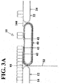
- metering mechanism 40 includes multiple, overlapping flexible platforms or flexible transfer devices 42 supported by a bearing surface.
- the platforms 42 move from upstream to downstream in a closed loop or path having arcuate portions. Specifically, each platform 42 moves from a loading position adjacent to the infeed conveyor 12 and a transfer position adjacent to the receiving conveyor 22. In the loading position, product on the infeed conveyor 12 is moved onto the platform 42. In the transfer position, product supported on platform 42 is transferred onto the receiving conveyor 22.
- the platforms 42 are formed of material with a flexibility to conform to and follow the arcuate portions of the closed path. The leading edge of each platform 42 is attached to one of multiple pairs of a drive mechanism.
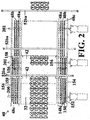
- the drive mechanism includes first, second, and third shafts 200, 201, 202 which are in a spaced, parallel relation and individually driven such as by servo motors.
- First, second and third pairs of roller chains 48a, 48b and 48c extend around sprockets on shafts 200 and 202.
- the sprockets 148a of the inner pair of chains 48a are rotatably fixed to shaft 202 and are rotatable on shaft 200.
- the sprockets 148b of the second pair of chains 48b are rotatably fixed to shaft 200 and are rotatable on shaft 202.
- the sprockets 148c of the outer pairs of chain 48c are rotatable on shafts 200 and 202, with the sprocket 148c on shaft 200 being suitably driven such as by being interconnected to a hub 150 rotatable on shaft 200 and interconnected to a drive sprocket 152 rotatable upon shaft 200.
- Sprocket 152 is suitably driven such as by a roller chain 154 extending around sprocket 156 fixed to shaft 201.
- a bracket 158 extends from adjacent each side of the leading edge of the platform 42 to one of the roller chains 48a, 48b, and 48c.
- each platform 42 is such that it is always overlapped by the leading edge of the trailing platform 42.
- Each platform 42 initially moves downstream at the speed of the infeed conveyor 12.
- Product is conveyed onto the platform 42 in the loading position over a transfer plate 44 from the infeed conveyor 12.
- An adjustable length transfer device 32 controls the point where the product comes in contact with a platform 42.
- the transfer device 32 is in the form of a flexible sheet extending around the upstream portion of the closed loop of the movement path of the platforms 42.
- the platform 42 accelerates in the conveying direction, separating the pack pattern from the continuous stream of product. Namely, a gap is created between the product on the platform 42 and the product remaining in the continuous stream of product on the infeed conveyor 12.
- a sweep bar 52ba moves down from an overhead path to enter the space created and abuts with the product on the platform 42 to push the product from the platform 42 and over a transfer plate 144 unto the receiving conveyor 22.
- the mechanism for inserting, moving and removing the sweep bars 52ba is not shown in the drawings for ease of illustration and can take a variety of forms as desired.
- the downstream movement is approximately equal to the receiving conveyor 22.
- Product on the platform 42 in the transfer position is conveyed across the transfer plate 144, assisted by the sweep bar 52ba, and onto the receiving conveyor 22 moving at a speed generally equal to the speed of the sweep bar 52ba.
- the platform 42 continues around the closed loop to the loading position of the metering mechanism 40 where the leading edge of the platform 42 is introduced into the product stream at the correct interval to support and form the next product group.
- Change over from one pack pattern to another and/or product dimension is accomplished by moving the downstream end of the adjustable length transfer device 32 either up or downstream and changing the dimension between the leading edges of the platforms 42.
- a first platform 42 is moving at a speed equal to the speed of the first product conveyance mechanism until a desired product group is moved over the transfer plate 44 and the transfer device 32 onto the first platform 42. Then, a second platform 42 is moved into the loading position and moves as fast as the first product conveyance mechanism to receive a second product group. The first platform 42 is accelerated relative to the product remaining in the continuous stream and to the product on the second platform 42. This allows continuous conveying of product at a constant speed and obtains a higher metering rate.
- overlap between the platforms 42 is greater when the length of product grouping is less and shorter when the length of product grouping is more. Changeover can occur without changing parts but by simply adjusting when the second platform 42 starts receiving product or by adjusting the amount that the first platform 42 is exposed (or the overlap). Although overlapping platforms 42 is believed to produce synergistic results, the platforms 42 can be arranged with the leading edge of the second platform 42 abutting or closely adjacent to the trailing edge of the first platform 42 to allow continuous conveyance such as in applications where changeover is not needed.
- three platforms 42 are shown in the preferred form, two or more than three platforms 42 can be utilized and still obtain the advantage of continuous motion. Advantages of utilizing three or more platforms 42 of the preferred form shown are that the length of the closed path can be longer and that the platforms 42 do not have to travel at a high rate of speed from the transfer position back to the loading position.
- an apparatus and methods utilizing a single platform can be constructed whereby a gap is created by relative acceleration of the platform 42 by stopping of the first product conveyance mechanism.
- the advantage of the closed path of the preferred form shown is that the platform 42 always travels in the same direction and never in the opposite direction so that vibration, shock, etc. are avoided.
- an apparatus could be constructed where the platform 42 accelerates product when traveling between the loading and transfer positions but does not travel along a closed path between the loading and transfer positions such as by reciprocation or other types of movements.
- each platform 42 is in motion at the same rate as the incoming product in the preferred form shown, there is less chance of tipping of product as the result of product being moved onto the platform 42. Furthermore, there is minimal scuffing of product as product does not slide onto or off the platform 42 in the preferred form shown. Furthermore, higher metering speeds are attainable, since product does not have to accelerate after contact with a conveying surface and since product is conveyed onto each platform 42. Further, product patterns are accelerated as a group, within the stability "envelope" of the product. This gives a consistent gap for introduction of the sweep bar 52ba. Further, apparatus 10 is open and, thus, allows easy access to the product from the top and side and to the bottom of apparatus 10 for maintenance and cleaning as well as jam clearance. Furthermore, apparatus 10 has no pins, etc. to puncture or deform product. Thus, waste and clean up are reduced.
- Apparatus 10 and methods for metering products do not need the presentation of windows between abutting product required in conventional designs. Furthermore, apparatus 10 and methods for metering products are versatile enough to meter product of different sizes and shapes including but not limited to cans, bottles, jars, cartons, bundles and trays. Furthermore, apparatus 10 and methods for metering products can be easily changed over between different product and/or different product group sizes. Furthermore, apparatus 10 and methods for metering products allow nesting of products in the continuous stream of product to minimize product surge. Further, apparatus 10 and methods for metering products minimize the number and complexity of components, with few high wear components. Further, apparatus 10 and methods for metering products eliminate or control physical registration forces during the metering operation.
- the product group does not have to directly engage the platform 42.
- a carton blank or the like can be placed on the platform 42 before it reaches its loading position so that product is pushed onto the carton blank located on the platform 42.
- the product group leaves the metering mechanism 40 on the carton blank.
- the output of apparatus 10 can be a stacker or a platform for pushing the product group onto or into a carton blank, a container, a package, or the like.
- the product group can be in the desired pack pattern as shown so that the product group is directly sent to the next station for packaging.
- the product group may not be in the desired pack pattern.
- the product group could be sent by the second product conveyance mechanism to a station or device for arranging the product group in the desired pack pattern before packaging.
Landscapes
- Engineering & Computer Science (AREA)
- Mechanical Engineering (AREA)
- Attitude Control For Articles On Conveyors (AREA)
- A Measuring Device Byusing Mechanical Method (AREA)
- Intermediate Stations On Conveyors (AREA)
- Maintenance And Management Of Digital Transmission (AREA)
- Radar Systems Or Details Thereof (AREA)
- Specific Conveyance Elements (AREA)
Claims (15)
- Procédé servant à mesurer des produits comprenant le fait de :déplacer un produit dans un flux continu dans une direction de transport sur une première plateforme (42) ;accélérer la première plateforme (42) portant sur elle le produit dans la direction de transport par rapport au produit restant dans le flux continu en créant un intervalle entre le produit sur la première plateforme et le produit restant dans le flux continu de produit ; ettransférer le produit de la première plateforme (42) vers une sortie après avoir créé l'intervalle entre le produit présent sur la première plateforme et le produit restant dans le flux continu de produit.
- Procédé selon la revendication 1, l'accélération de la première plateforme comportant le fait de déplacer la première plateforme dans un parcours fermé.
- Procédé selon la revendication 2, le déplacement de la première plateforme comprenant le fait de déplacer la première plateforme dans le parcours fermé qui comporte des parties courbées en arc, le déplacement de la première plateforme comprenant le fait de déplacer la première plateforme constituée de matériau doté de souplesse afin de se conformer aux, et de suivre les, parties courbées en arc du parcours fermé.
- Procédé selon l'une quelconque des revendications précédentes, le déplacement du produit dans le flux continu comprenant le fait de déplacer le produit dans le flux continu à une première vitesse sur la première plateforme se déplaçant initialement à la première vitesse dans la direction de transport.
- Procédé selon l'une quelconque des revendications précédentes, comprenant, de plus :le fait de déplacer le produit restant dans le flux continu à la première vitesse dans la direction de transport sur une seconde plateforme se déplaçant initialement à la première vitesse dans la direction de transport lorsque la première plateforme portant sur elle le produit est accélérée, le déplacement de produit dans le flux continu comprenant le fait de déplacer en continu le produit dans le flux continu à la première vitesse.
- Procédé selon la revendication 5, le déplacement du produit restant dans le flux continu comprenant le fait de déplacer le produit restant dans le flux continu sur la seconde plateforme qui se superpose à la première plateforme.
- Procédé selon l'une quelconque des revendications précédentes comprenant, de plus, le fait d'insérer une barre de balayage dans l'intervalle entre le produit se trouvant sur la première plateforme et le produit restant dans le flux continu et d'amener en butée contre la barre de balayage le produit se trouvant sur la première plateforme avant de transférer le produit à partir de la première plateforme et en vue d'aider au transfert du produit présent sur la première plateforme vers la sortie, le transfert du produit à partir de la première plateforme vers la sortie comprenant le fait de déplacer un mécanisme de transport de produit en aval de la première plateforme à une seconde vitesse généralement égale à une vitesse de la barre de balayage, le déplacement du mécanisme de transport du produit comportant le fait de placer le mécanisme de transport du produit dans une direction colinéaire à la direction de transport.
- Appareil de mesure de produits comprenant, en combinaison :un premier mécanisme de transport de produit (12) transportant le produit dans un flux continu dans une direction de transport ;une sortie (22) distante du premier mécanisme de transport de produit dans la direction de transport ;une première plateforme (42) pour supporter un produit, la première plateforme étant mobile entre une position de chargement adjacente au premier mécanisme de transport de produit et une position de transfert adjacente à la sortie (22), la première plateforme dans la position de chargement recevant le produit dans le flux continu à partir du premier mécanisme de transport, caractérisé en ce que la première plateforme se déplace de la positon de chargement à la position de transfert à une vitesse supérieure à celle du premier mécanisme de transport de produit après que le produit du flux continu a été déplacé sur la première plateforme créant un intervalle entre le produit supporté sur la première plateforme et le produit restant dans le flux continu sur le premier mécanisme de transport de produit , le produit supporté sur la première plateforme dans la position de transfert étant transféré vers la sortie.
- Appareil de mesure de produit selon la revendication 8 comprenant, de plus, en combinaison : une surface de support se déplaçant suivant un parcours fermé, la première plateforme étant supportée par, et se déplaçant avec, la surface de support suivant le parcours fermé.
- Appareil de mesure de produit selon la revendication 9, le parcours fermé comportant des parties courbées en arc et la première plateforme étant constituée d'un matériau doté de souplesse afin de se conformer aux, et de suivre les, parties courbées en arc du parcours fermé.
- Appareil de mesure de produit selon la revendication 9 ou 10 comprenant, de plus, en combinaison :une plaque souple de longueur réglable (32) ayant une extrémité s'étendant autour d'une partie amont du parcours fermé, la plaque souple de longueur réglable commandant le point au niveau duquel le flux continu de produit provenant du premier mécanisme de transport de produit vient en contact avec la première plateforme ; etune plaque de transfert (44) s'étendant entre la partie amont du parcours fermé et une partie aval du premier mécanisme de transport de produit et le premier mécanisme de transport de produit déplaçant le produit dans le flux continu à travers la plaque de transfert et l'extrémité de la plaque souple de longueur réglable sur la première plateforme.
- Appareil de mesure de produit selon l'une quelconque des revendications 8 à 11, la première plateforme se déplaçant initialement à une première vitesse dans la direction de transport égale à une vitesse du produit du flux continu sur le premier mécanisme de transport de produit.
- Appareil de mesure de produit selon l'une quelconque des revendications 8 à 12 comprenant, de plus, en combinaison : une seconde plateforme mobile suivant le parcours fermé entre la position de chargement et la position de transfert, la seconde plateforme se déplaçant initialement à la première vitesse dans la direction de transport lorsque la première plateforme portant sur elle le produit est accélérée, la seconde plateforme dans la position de chargement recevant le produit restant dans le flux continu après que la première plateforme portant sur elle le produit est accélérée, la seconde plateforme se déplaçant de la position de chargement à la position de transfert à une vitesse plus grande que celle du premier mécanisme de transport de produit après que le produit du flux continu se soit déplacé sur la seconde plateforme créant un intervalle entre le produit supporté sur la seconde plateforme et le produit restant dans le flux continu sur le premier mécanisme de transport de produit, le produit supporté sur la seconde plateforme dans la position de transfert étant transféré vers la sortie, et le premier mécanisme de transport de produit se déplaçant en continu à la première vitesse.
- Appareil de mesure de produit selon la revendication 13, la seconde plateforme dans la position de chargement étant en superposition avec la première plateforme, l'appareil de mesure de produit comprenant, de plus, en combinaison : un mécanisme d'entraînement comportant :une première et une seconde paires d'arbres (200, 201) placées suivant une relation parallèle et à distance et entraînée individuellement, chacune des première et seconde paires d'arbres s'étendant dans une direction perpendiculaire à la direction de transport et incluant des premières et secondes extrémités sur les deux côtés du parcours fermé ;des pignons à dents (18a, 18b) montés sur les premières extrémités et les secondes extrémités de la première et de la seconde paires d'arbres ; etdes premières et secondes chaînes (48a, 48b) montées, chacune, autour des pignons à dents de la première et de la seconde paires d'arbres et raccordées à un bord de guidage de l'une de la première et de la seconde plateformes.
- Appareil de mesure de produit selon l'une quelconque des revendications 8 à 14 comprenant, de plus, en combinaison :une barre de balayage (52ba) insérée dans l'intervalle formé entre le produit situé sur la première plateforme et le produit restant dans le flux continu de produit, entre la position de chargement et la position de transfert, la barre de balayage venant en butée contre le produit se trouvant sur la première plateforme et aidant au transfert du produit sur la première plateforme vers la sortie, la sortie comprenant un second mécanisme de transport de produit en aval de la première plateforme, le second mécanisme de transport de produit se déplaçant à une vitesse généralement égale à une vitesse de la barre de balayage, le second mécanisme de transport de produit se déplaçant dans une direction colinéaire à la direction de transport.
Applications Claiming Priority (2)
| Application Number | Priority Date | Filing Date | Title |
|---|---|---|---|
| US96826807P | 2007-08-27 | 2007-08-27 | |
| PCT/US2008/074424 WO2009029646A1 (fr) | 2007-08-27 | 2008-08-27 | Appareil de mesure de dispositif de transfert et procédés |
Publications (2)
| Publication Number | Publication Date |
|---|---|
| EP2195265A1 EP2195265A1 (fr) | 2010-06-16 |
| EP2195265B1 true EP2195265B1 (fr) | 2011-03-02 |
Family
ID=39817157
Family Applications (1)
| Application Number | Title | Priority Date | Filing Date |
|---|---|---|---|
| EP08828489A Not-in-force EP2195265B1 (fr) | 2007-08-27 | 2008-08-27 | Appareil de mesure de dispositif de transfert et procédés |
Country Status (5)
| Country | Link |
|---|---|
| US (1) | US8011495B2 (fr) |
| EP (1) | EP2195265B1 (fr) |
| AT (1) | ATE500173T1 (fr) |
| DE (1) | DE602008005334D1 (fr) |
| WO (1) | WO2009029646A1 (fr) |
Families Citing this family (12)
| Publication number | Priority date | Publication date | Assignee | Title |
|---|---|---|---|---|
| EP2293997B1 (fr) * | 2008-05-19 | 2012-02-29 | Douglas Machine, Inc. | Procédés et appareils de comptage de palettes souples pour un produit d'indexation |
| DE202008011454U1 (de) * | 2008-08-28 | 2008-10-30 | Khs Ag | Vorrichtung zur Abteilung von Produktgruppen |
| FR2966806B1 (fr) * | 2010-10-28 | 2014-01-17 | Sidel Participations | Installation pour la preparation de lots de produits, du genre flacons, bouteilles ou autres |
| MX350114B (es) | 2012-01-18 | 2017-08-28 | Douglas Machine Inc | Aparato, sistema y métodos para dosificar artículos. |
| DE102012003500C5 (de) | 2012-02-22 | 2017-12-21 | Multivac Sepp Haggenmüller Se & Co. Kg | Zuführvorrichtung mit Steuereinheit zur Anpassung der Geschwindigkeit der Förderbänder |
| US9073703B2 (en) * | 2013-05-20 | 2015-07-07 | Laitram, L.L.C. | Apparatus and methods for dynamically controlling the spacing of conveyed objects |
| US9205995B2 (en) | 2013-10-21 | 2015-12-08 | International Business Machines Corporation | Sorting, swapping, and organizing objects on transfer ball grids |
| EP3053443B1 (fr) * | 2015-02-03 | 2018-04-11 | Albert Handtmann Maschinenfabrik GmbH & Co. KG | Dispositif de regroupement de saucisses et procédé destiné à regrouper des saucisses dans des groupes de saucisses |
| US9688473B2 (en) * | 2015-03-02 | 2017-06-27 | Lorin Reed | Conveying systems and methods of use |
| CN104973407B (zh) * | 2015-06-08 | 2017-06-09 | 温州职业技术学院 | 玻璃瓶罐自动排列输送系统 |
| US10618740B2 (en) | 2017-11-22 | 2020-04-14 | Lorin Reed | Produce conveying and sizing equipment |
| US10549924B2 (en) | 2018-06-22 | 2020-02-04 | Douglas Machine Inc. | Robotic article collation and metering assembly |
Family Cites Families (8)
| Publication number | Priority date | Publication date | Assignee | Title |
|---|---|---|---|---|
| US3403772A (en) * | 1967-01-05 | 1968-10-01 | Fmc Corp | Container feed mechanism |
| US3938650A (en) * | 1975-02-27 | 1976-02-17 | Franklin Electric Subsidiaries, Inc. | Indexing article separating and feeding conveyor |
| IT1097322B (it) * | 1978-07-25 | 1985-08-31 | Ocme Spa | Dispositivo di alimentazione ad intermittenza di oggetti da confezionare in macchine confezionatrici |
| US4771877A (en) * | 1987-05-05 | 1988-09-20 | H. J. Langen & Sons Limited | Load spacing conveyor system |
| DE3819348C1 (fr) * | 1988-06-07 | 1989-09-07 | Otto Haensel Gmbh, 3000 Hannover, De | |
| US5012916A (en) * | 1988-10-13 | 1991-05-07 | Formost Packaging Machines, Inc. | Article group-segregating apparatus and method |
| ITBO940215A1 (it) * | 1994-05-16 | 1995-11-16 | Baumer Srl | Sistema per disporre in passo e/o distanziare e compattare longitudinalmente file di oggetti allineati trasversalmente |
| US6843360B2 (en) | 2002-03-27 | 2005-01-18 | Douglas Machine, Inc. | Retractable transfer device metering apparatus and methods |
-
2008
- 2008-08-27 US US12/675,451 patent/US8011495B2/en not_active Expired - Fee Related
- 2008-08-27 WO PCT/US2008/074424 patent/WO2009029646A1/fr active Application Filing
- 2008-08-27 AT AT08828489T patent/ATE500173T1/de not_active IP Right Cessation
- 2008-08-27 EP EP08828489A patent/EP2195265B1/fr not_active Not-in-force
- 2008-08-27 DE DE602008005334T patent/DE602008005334D1/de active Active
Also Published As
| Publication number | Publication date |
|---|---|
| US20100243407A1 (en) | 2010-09-30 |
| WO2009029646A1 (fr) | 2009-03-05 |
| US8011495B2 (en) | 2011-09-06 |
| EP2195265A1 (fr) | 2010-06-16 |
| DE602008005334D1 (de) | 2011-04-14 |
| ATE500173T1 (de) | 2011-03-15 |
Similar Documents
| Publication | Publication Date | Title |
|---|---|---|
| EP2195265B1 (fr) | Appareil de mesure de dispositif de transfert et procédés | |
| EP2293997B1 (fr) | Procédés et appareils de comptage de palettes souples pour un produit d'indexation | |
| EP1490280B1 (fr) | Dispositif de transfert retractable pour un appareil de comptage | |
| US8584828B2 (en) | Flexible retractable transfer device metering apparatus and methods | |
| US6793064B2 (en) | Retractable transfer device metering and product arranging and loading apparatus and methods | |
| FI90751B (fi) | Artikkeleidenerottelu ja -pakkauslaite | |
| US7533768B2 (en) | Retractable transfer device metering apparatus and methods | |
| AU685325B2 (en) | Apparatus and method for pushing articles into receptacle | |
| CN111655585B (zh) | 具有纸箱翻转站的连续运动包装机 | |
| KR19980703513A (ko) | 멀티 팩 포장 장치 | |
| WO2010096111A1 (fr) | Procédés et appareil pour créer des motifs d’emballage décalés | |
| US4759433A (en) | Continuous motion, in-line product stacking apparatus | |
| EP0673342B1 (fr) | Procede et appareil d'empilage reorientant des articles le long d'une ligne generalement helicoidale tout en les transportant d'une station de chargement a une station de dechargement | |
| US6837360B2 (en) | Retractable transfer device metering and product arranging apparatus and methods | |
| EP0711719A1 (fr) | Méthode pour transférer à distances égales des produits et liquide de transport à cet effet | |
| EP0608103B1 (fr) | Système de transport à poussoirs pour cartons en machines d'emballage |
Legal Events
| Date | Code | Title | Description |
|---|---|---|---|
| PUAI | Public reference made under article 153(3) epc to a published international application that has entered the european phase |
Free format text: ORIGINAL CODE: 0009012 |
|
| 17P | Request for examination filed |
Effective date: 20100318 |
|
| AK | Designated contracting states |
Kind code of ref document: A1 Designated state(s): AT BE BG CH CY CZ DE DK EE ES FI FR GB GR HR HU IE IS IT LI LT LU LV MC MT NL NO PL PT RO SE SI SK TR |
|
| AX | Request for extension of the european patent |
Extension state: AL BA MK RS |
|
| GRAP | Despatch of communication of intention to grant a patent |
Free format text: ORIGINAL CODE: EPIDOSNIGR1 |
|
| DAX | Request for extension of the european patent (deleted) | ||
| GRAS | Grant fee paid |
Free format text: ORIGINAL CODE: EPIDOSNIGR3 |
|
| GRAA | (expected) grant |
Free format text: ORIGINAL CODE: 0009210 |
|
| AK | Designated contracting states |
Kind code of ref document: B1 Designated state(s): AT BE BG CH CY CZ DE DK EE ES FI FR GB GR HR HU IE IS IT LI LT LU LV MC MT NL NO PL PT RO SE SI SK TR |
|
| REG | Reference to a national code |
Ref country code: GB Ref legal event code: FG4D |
|
| REG | Reference to a national code |
Ref country code: CH Ref legal event code: EP |
|
| REG | Reference to a national code |
Ref country code: IE Ref legal event code: FG4D |
|
| REF | Corresponds to: |
Ref document number: 602008005334 Country of ref document: DE Date of ref document: 20110414 Kind code of ref document: P |
|
| REG | Reference to a national code |
Ref country code: DE Ref legal event code: R096 Ref document number: 602008005334 Country of ref document: DE Effective date: 20110414 |
|
| REG | Reference to a national code |
Ref country code: NL Ref legal event code: VDEP Effective date: 20110302 |
|
| PG25 | Lapsed in a contracting state [announced via postgrant information from national office to epo] |
Ref country code: GR Free format text: LAPSE BECAUSE OF FAILURE TO SUBMIT A TRANSLATION OF THE DESCRIPTION OR TO PAY THE FEE WITHIN THE PRESCRIBED TIME-LIMIT Effective date: 20110603 Ref country code: SE Free format text: LAPSE BECAUSE OF FAILURE TO SUBMIT A TRANSLATION OF THE DESCRIPTION OR TO PAY THE FEE WITHIN THE PRESCRIBED TIME-LIMIT Effective date: 20110302 Ref country code: HR Free format text: LAPSE BECAUSE OF FAILURE TO SUBMIT A TRANSLATION OF THE DESCRIPTION OR TO PAY THE FEE WITHIN THE PRESCRIBED TIME-LIMIT Effective date: 20110302 Ref country code: LV Free format text: LAPSE BECAUSE OF FAILURE TO SUBMIT A TRANSLATION OF THE DESCRIPTION OR TO PAY THE FEE WITHIN THE PRESCRIBED TIME-LIMIT Effective date: 20110302 Ref country code: NO Free format text: LAPSE BECAUSE OF FAILURE TO SUBMIT A TRANSLATION OF THE DESCRIPTION OR TO PAY THE FEE WITHIN THE PRESCRIBED TIME-LIMIT Effective date: 20110602 Ref country code: ES Free format text: LAPSE BECAUSE OF FAILURE TO SUBMIT A TRANSLATION OF THE DESCRIPTION OR TO PAY THE FEE WITHIN THE PRESCRIBED TIME-LIMIT Effective date: 20110613 Ref country code: LT Free format text: LAPSE BECAUSE OF FAILURE TO SUBMIT A TRANSLATION OF THE DESCRIPTION OR TO PAY THE FEE WITHIN THE PRESCRIBED TIME-LIMIT Effective date: 20110302 |
|
| LTIE | Lt: invalidation of european patent or patent extension |
Effective date: 20110302 |
|
| PG25 | Lapsed in a contracting state [announced via postgrant information from national office to epo] |
Ref country code: CY Free format text: LAPSE BECAUSE OF FAILURE TO SUBMIT A TRANSLATION OF THE DESCRIPTION OR TO PAY THE FEE WITHIN THE PRESCRIBED TIME-LIMIT Effective date: 20110302 Ref country code: NL Free format text: LAPSE BECAUSE OF FAILURE TO SUBMIT A TRANSLATION OF THE DESCRIPTION OR TO PAY THE FEE WITHIN THE PRESCRIBED TIME-LIMIT Effective date: 20110302 Ref country code: FI Free format text: LAPSE BECAUSE OF FAILURE TO SUBMIT A TRANSLATION OF THE DESCRIPTION OR TO PAY THE FEE WITHIN THE PRESCRIBED TIME-LIMIT Effective date: 20110302 Ref country code: BG Free format text: LAPSE BECAUSE OF FAILURE TO SUBMIT A TRANSLATION OF THE DESCRIPTION OR TO PAY THE FEE WITHIN THE PRESCRIBED TIME-LIMIT Effective date: 20110602 Ref country code: SI Free format text: LAPSE BECAUSE OF FAILURE TO SUBMIT A TRANSLATION OF THE DESCRIPTION OR TO PAY THE FEE WITHIN THE PRESCRIBED TIME-LIMIT Effective date: 20110302 Ref country code: AT Free format text: LAPSE BECAUSE OF FAILURE TO SUBMIT A TRANSLATION OF THE DESCRIPTION OR TO PAY THE FEE WITHIN THE PRESCRIBED TIME-LIMIT Effective date: 20110302 |
|
| PG25 | Lapsed in a contracting state [announced via postgrant information from national office to epo] |
Ref country code: BE Free format text: LAPSE BECAUSE OF FAILURE TO SUBMIT A TRANSLATION OF THE DESCRIPTION OR TO PAY THE FEE WITHIN THE PRESCRIBED TIME-LIMIT Effective date: 20110302 |
|
| PG25 | Lapsed in a contracting state [announced via postgrant information from national office to epo] |
Ref country code: PT Free format text: LAPSE BECAUSE OF FAILURE TO SUBMIT A TRANSLATION OF THE DESCRIPTION OR TO PAY THE FEE WITHIN THE PRESCRIBED TIME-LIMIT Effective date: 20110704 Ref country code: EE Free format text: LAPSE BECAUSE OF FAILURE TO SUBMIT A TRANSLATION OF THE DESCRIPTION OR TO PAY THE FEE WITHIN THE PRESCRIBED TIME-LIMIT Effective date: 20110302 |
|
| PG25 | Lapsed in a contracting state [announced via postgrant information from national office to epo] |
Ref country code: SK Free format text: LAPSE BECAUSE OF FAILURE TO SUBMIT A TRANSLATION OF THE DESCRIPTION OR TO PAY THE FEE WITHIN THE PRESCRIBED TIME-LIMIT Effective date: 20110302 Ref country code: IS Free format text: LAPSE BECAUSE OF FAILURE TO SUBMIT A TRANSLATION OF THE DESCRIPTION OR TO PAY THE FEE WITHIN THE PRESCRIBED TIME-LIMIT Effective date: 20110702 Ref country code: RO Free format text: LAPSE BECAUSE OF FAILURE TO SUBMIT A TRANSLATION OF THE DESCRIPTION OR TO PAY THE FEE WITHIN THE PRESCRIBED TIME-LIMIT Effective date: 20110302 Ref country code: CZ Free format text: LAPSE BECAUSE OF FAILURE TO SUBMIT A TRANSLATION OF THE DESCRIPTION OR TO PAY THE FEE WITHIN THE PRESCRIBED TIME-LIMIT Effective date: 20110302 |
|
| PG25 | Lapsed in a contracting state [announced via postgrant information from national office to epo] |
Ref country code: MT Free format text: LAPSE BECAUSE OF FAILURE TO SUBMIT A TRANSLATION OF THE DESCRIPTION OR TO PAY THE FEE WITHIN THE PRESCRIBED TIME-LIMIT Effective date: 20110302 |
|
| PLBE | No opposition filed within time limit |
Free format text: ORIGINAL CODE: 0009261 |
|
| STAA | Information on the status of an ep patent application or granted ep patent |
Free format text: STATUS: NO OPPOSITION FILED WITHIN TIME LIMIT |
|
| 26N | No opposition filed |
Effective date: 20111205 |
|
| PG25 | Lapsed in a contracting state [announced via postgrant information from national office to epo] |
Ref country code: PL Free format text: LAPSE BECAUSE OF FAILURE TO SUBMIT A TRANSLATION OF THE DESCRIPTION OR TO PAY THE FEE WITHIN THE PRESCRIBED TIME-LIMIT Effective date: 20110302 Ref country code: DK Free format text: LAPSE BECAUSE OF FAILURE TO SUBMIT A TRANSLATION OF THE DESCRIPTION OR TO PAY THE FEE WITHIN THE PRESCRIBED TIME-LIMIT Effective date: 20110302 |
|
| REG | Reference to a national code |
Ref country code: DE Ref legal event code: R097 Ref document number: 602008005334 Country of ref document: DE Effective date: 20111205 |
|
| PG25 | Lapsed in a contracting state [announced via postgrant information from national office to epo] |
Ref country code: MC Free format text: LAPSE BECAUSE OF NON-PAYMENT OF DUE FEES Effective date: 20110831 |
|
| REG | Reference to a national code |
Ref country code: FR Ref legal event code: ST Effective date: 20120430 |
|
| REG | Reference to a national code |
Ref country code: IE Ref legal event code: MM4A |
|
| PG25 | Lapsed in a contracting state [announced via postgrant information from national office to epo] |
Ref country code: IE Free format text: LAPSE BECAUSE OF NON-PAYMENT OF DUE FEES Effective date: 20110827 |
|
| PG25 | Lapsed in a contracting state [announced via postgrant information from national office to epo] |
Ref country code: FR Free format text: LAPSE BECAUSE OF NON-PAYMENT OF DUE FEES Effective date: 20110831 |
|
| REG | Reference to a national code |
Ref country code: CH Ref legal event code: PL |
|
| GBPC | Gb: european patent ceased through non-payment of renewal fee |
Effective date: 20120827 |
|
| PG25 | Lapsed in a contracting state [announced via postgrant information from national office to epo] |
Ref country code: CH Free format text: LAPSE BECAUSE OF NON-PAYMENT OF DUE FEES Effective date: 20120831 Ref country code: LI Free format text: LAPSE BECAUSE OF NON-PAYMENT OF DUE FEES Effective date: 20120831 |
|
| PG25 | Lapsed in a contracting state [announced via postgrant information from national office to epo] |
Ref country code: LU Free format text: LAPSE BECAUSE OF NON-PAYMENT OF DUE FEES Effective date: 20110827 |
|
| PG25 | Lapsed in a contracting state [announced via postgrant information from national office to epo] |
Ref country code: GB Free format text: LAPSE BECAUSE OF NON-PAYMENT OF DUE FEES Effective date: 20120827 |
|
| PG25 | Lapsed in a contracting state [announced via postgrant information from national office to epo] |
Ref country code: TR Free format text: LAPSE BECAUSE OF FAILURE TO SUBMIT A TRANSLATION OF THE DESCRIPTION OR TO PAY THE FEE WITHIN THE PRESCRIBED TIME-LIMIT Effective date: 20110302 |
|
| PG25 | Lapsed in a contracting state [announced via postgrant information from national office to epo] |
Ref country code: HU Free format text: LAPSE BECAUSE OF FAILURE TO SUBMIT A TRANSLATION OF THE DESCRIPTION OR TO PAY THE FEE WITHIN THE PRESCRIBED TIME-LIMIT Effective date: 20110302 |
|
| REG | Reference to a national code |
Ref country code: DE Ref legal event code: R082 Ref document number: 602008005334 Country of ref document: DE Representative=s name: FRIESE GOEDEN PATENTANWAELTE PARTGMBB, DE Ref country code: DE Ref legal event code: R082 Ref document number: 602008005334 Country of ref document: DE Representative=s name: FRIESE GOEDEN, DE Ref country code: DE Ref legal event code: R082 Ref document number: 602008005334 Country of ref document: DE Representative=s name: FRIESE GOEDEN PATENTANWAELTE, DE Ref country code: DE Ref legal event code: R082 Ref document number: 602008005334 Country of ref document: DE Representative=s name: ANDRAE WESTENDORP PATENTANWAELTE PARTNERSCHAFT, DE |
|
| PGFP | Annual fee paid to national office [announced via postgrant information from national office to epo] |
Ref country code: DE Payment date: 20150821 Year of fee payment: 8 |
|
| PGFP | Annual fee paid to national office [announced via postgrant information from national office to epo] |
Ref country code: IT Payment date: 20150821 Year of fee payment: 8 |
|
| REG | Reference to a national code |
Ref country code: DE Ref legal event code: R082 Ref document number: 602008005334 Country of ref document: DE Representative=s name: FRIESE GOEDEN PATENTANWAELTE PARTGMBB, DE Ref country code: DE Ref legal event code: R082 Ref document number: 602008005334 Country of ref document: DE Representative=s name: FRIESE GOEDEN, DE Ref country code: DE Ref legal event code: R082 Ref document number: 602008005334 Country of ref document: DE Representative=s name: FRIESE GOEDEN PATENTANWAELTE, DE |
|
| REG | Reference to a national code |
Ref country code: DE Ref legal event code: R119 Ref document number: 602008005334 Country of ref document: DE |
|
| PG25 | Lapsed in a contracting state [announced via postgrant information from national office to epo] |
Ref country code: DE Free format text: LAPSE BECAUSE OF NON-PAYMENT OF DUE FEES Effective date: 20170301 |
|
| PG25 | Lapsed in a contracting state [announced via postgrant information from national office to epo] |
Ref country code: IT Free format text: LAPSE BECAUSE OF NON-PAYMENT OF DUE FEES Effective date: 20160827 |