EP2194701A2 - Modul zur dynamischen Anpassung der Länge einer optischen Weglänge, optischer Sensor und digitales Multifunktions-Gerät mit mindestens einem solchen Modul - Google Patents
Modul zur dynamischen Anpassung der Länge einer optischen Weglänge, optischer Sensor und digitales Multifunktions-Gerät mit mindestens einem solchen Modul Download PDFInfo
- Publication number
- EP2194701A2 EP2194701A2 EP09290873A EP09290873A EP2194701A2 EP 2194701 A2 EP2194701 A2 EP 2194701A2 EP 09290873 A EP09290873 A EP 09290873A EP 09290873 A EP09290873 A EP 09290873A EP 2194701 A2 EP2194701 A2 EP 2194701A2
- Authority
- EP
- European Patent Office
- Prior art keywords
- mirrors
- carriage
- series
- module
- optical path
- Prior art date
- Legal status (The legal status is an assumption and is not a legal conclusion. Google has not performed a legal analysis and makes no representation as to the accuracy of the status listed.)
- Withdrawn
Links
Images


Classifications
-
- H—ELECTRICITY
- H04—ELECTRIC COMMUNICATION TECHNIQUE
- H04N—PICTORIAL COMMUNICATION, e.g. TELEVISION
- H04N1/00—Scanning, transmission or reproduction of documents or the like, e.g. facsimile transmission; Details thereof
- H04N1/04—Scanning arrangements, i.e. arrangements for the displacement of active reading or reproducing elements relative to the original or reproducing medium, or vice versa
- H04N1/0402—Scanning different formats; Scanning with different densities of dots per unit length, e.g. different numbers of dots per inch (dpi); Conversion of scanning standards
-
- H—ELECTRICITY
- H04—ELECTRIC COMMUNICATION TECHNIQUE
- H04N—PICTORIAL COMMUNICATION, e.g. TELEVISION
- H04N1/00—Scanning, transmission or reproduction of documents or the like, e.g. facsimile transmission; Details thereof
- H04N1/024—Details of scanning heads ; Means for illuminating the original
- H04N1/028—Details of scanning heads ; Means for illuminating the original for picture information pick-up
- H04N1/03—Details of scanning heads ; Means for illuminating the original for picture information pick-up with photodetectors arranged in a substantially linear array
- H04N1/0301—Details of scanning heads ; Means for illuminating the original for picture information pick-up with photodetectors arranged in a substantially linear array using a bent optical path between the scanned line and the photodetector array, e.g. a folded optical path
- H04N1/0305—Details of scanning heads ; Means for illuminating the original for picture information pick-up with photodetectors arranged in a substantially linear array using a bent optical path between the scanned line and the photodetector array, e.g. a folded optical path with multiple folds of the optical path
-
- H—ELECTRICITY
- H04—ELECTRIC COMMUNICATION TECHNIQUE
- H04N—PICTORIAL COMMUNICATION, e.g. TELEVISION
- H04N1/00—Scanning, transmission or reproduction of documents or the like, e.g. facsimile transmission; Details thereof
- H04N1/024—Details of scanning heads ; Means for illuminating the original
- H04N1/028—Details of scanning heads ; Means for illuminating the original for picture information pick-up
- H04N1/03—Details of scanning heads ; Means for illuminating the original for picture information pick-up with photodetectors arranged in a substantially linear array
- H04N1/0308—Details of scanning heads ; Means for illuminating the original for picture information pick-up with photodetectors arranged in a substantially linear array characterised by the design of the photodetectors, e.g. shape
-
- H—ELECTRICITY
- H04—ELECTRIC COMMUNICATION TECHNIQUE
- H04N—PICTORIAL COMMUNICATION, e.g. TELEVISION
- H04N1/00—Scanning, transmission or reproduction of documents or the like, e.g. facsimile transmission; Details thereof
- H04N1/04—Scanning arrangements, i.e. arrangements for the displacement of active reading or reproducing elements relative to the original or reproducing medium, or vice versa
- H04N1/0402—Scanning different formats; Scanning with different densities of dots per unit length, e.g. different numbers of dots per inch (dpi); Conversion of scanning standards
- H04N1/042—Details of the method used
- H04N1/0423—Switching between or selecting from a plurality of optical paths
-
- H—ELECTRICITY
- H04—ELECTRIC COMMUNICATION TECHNIQUE
- H04N—PICTORIAL COMMUNICATION, e.g. TELEVISION
- H04N1/00—Scanning, transmission or reproduction of documents or the like, e.g. facsimile transmission; Details thereof
- H04N1/04—Scanning arrangements, i.e. arrangements for the displacement of active reading or reproducing elements relative to the original or reproducing medium, or vice versa
- H04N1/0402—Scanning different formats; Scanning with different densities of dots per unit length, e.g. different numbers of dots per inch (dpi); Conversion of scanning standards
- H04N1/042—Details of the method used
- H04N1/044—Tilting an optical element, e.g. a refractive plate
-
- H—ELECTRICITY
- H04—ELECTRIC COMMUNICATION TECHNIQUE
- H04N—PICTORIAL COMMUNICATION, e.g. TELEVISION
- H04N1/00—Scanning, transmission or reproduction of documents or the like, e.g. facsimile transmission; Details thereof
- H04N1/04—Scanning arrangements, i.e. arrangements for the displacement of active reading or reproducing elements relative to the original or reproducing medium, or vice versa
- H04N1/113—Scanning arrangements, i.e. arrangements for the displacement of active reading or reproducing elements relative to the original or reproducing medium, or vice versa using oscillating or rotating mirrors
-
- H—ELECTRICITY
- H04—ELECTRIC COMMUNICATION TECHNIQUE
- H04N—PICTORIAL COMMUNICATION, e.g. TELEVISION
- H04N2201/00—Indexing scheme relating to scanning, transmission or reproduction of documents or the like, and to details thereof
- H04N2201/04—Scanning arrangements
- H04N2201/0402—Arrangements not specific to a particular one of the scanning methods covered by groups H04N1/04 - H04N1/207
- H04N2201/0418—Arrangements not specific to a particular one of the scanning methods covered by groups H04N1/04 - H04N1/207 capable of scanning transmissive and reflective originals at a single scanning station
-
- H—ELECTRICITY
- H04—ELECTRIC COMMUNICATION TECHNIQUE
- H04N—PICTORIAL COMMUNICATION, e.g. TELEVISION
- H04N2201/00—Indexing scheme relating to scanning, transmission or reproduction of documents or the like, and to details thereof
- H04N2201/04—Scanning arrangements
- H04N2201/047—Detection, control or error compensation of scanning velocity or position
- H04N2201/04701—Detection of scanning velocity or position
- H04N2201/04748—Detection of scanning velocity or position by detecting synchronisation signals or driving signals, e.g. page sync
-
- H—ELECTRICITY
- H04—ELECTRIC COMMUNICATION TECHNIQUE
- H04N—PICTORIAL COMMUNICATION, e.g. TELEVISION
- H04N2201/00—Indexing scheme relating to scanning, transmission or reproduction of documents or the like, and to details thereof
- H04N2201/04—Scanning arrangements
- H04N2201/047—Detection, control or error compensation of scanning velocity or position
- H04N2201/04753—Control or error compensation of scanning position or velocity
- H04N2201/04755—Control or error compensation of scanning position or velocity by controlling the position or movement of a scanning element or carriage, e.g. of a polygonal mirror, of a drive motor
-
- H—ELECTRICITY
- H04—ELECTRIC COMMUNICATION TECHNIQUE
- H04N—PICTORIAL COMMUNICATION, e.g. TELEVISION
- H04N2201/00—Indexing scheme relating to scanning, transmission or reproduction of documents or the like, and to details thereof
- H04N2201/04—Scanning arrangements
- H04N2201/047—Detection, control or error compensation of scanning velocity or position
- H04N2201/04753—Control or error compensation of scanning position or velocity
- H04N2201/04794—Varying the control or compensation during the scan, e.g. using continuous feedback or from line to line
Definitions
- the present invention relates to a module for dynamically adjusting the length of an optical path, a trolley or an optical sensor equipped with such a module as well as a multifunction scanning device equipped with at least one dynamic adjustment module in order to digitize successively different sources.
- the dynamic length adjustment module of an optical path of the present invention will be particularly intended to equip multi-function scanning devices that can perform various tasks such as printing, scans or transmissions of documents, the loading of documents. performing by placing the documents in one or more chargers or by placing them on a window allowing the optical reading of the document flat.
- an optical sensor for the optical reading of documents it is either an optical sensor disposed in a mobile carriage, said carriage scanning the surface to be digitized, or a separate fixed optical sensor mobile cart.
- One of the disadvantages of the optical sensor disposed in the carriage is that it is necessary to multiply the number of optical modules in multifunction devices that have several paper path circuits with for example a path for performing an optical reading of the front of a document from the charger or disposed on the scanning glass, another path for the back of such documents and a last path for scanning the output of the printer.
- the multifunction scanning devices comprises an optical sensor 3 placed in a carriage 2 which makes it possible to translate it horizontally by means of a belt 5, in order to be able to digitize, as desired, a document from the scanner loading through the window 51 or a document 60 disposed on the window of the scrolling scanner 52.
- the optical sensor is fixed under the window of the loading scanner 51.
- the user uses the scrolling scanner, he deposits his document to be scanned 60 on the scrolling scanner glass 52, and the carriage then translates the sensor using the belt 5 along the document in order to digitize its face. lower.
- the two panes 51 and 52 are advantageously of identical thickness.
- the optical carriage is then systematically attached to the document to be digitized behind a glass of known thickness in order to have an optical path separating the document from the constant optical sensor and corresponding to the focusing of the sensor, whatever the position of the carriage.
- This architecture prevents the realization of certain functions that would improve the scanning device. Indeed, access to the output of the printer and the back side of a scanner scrolling by the same sensor that already performs the scans of the loading scanner part and the front part of the document would be particularly interesting. In particular, this access would make it possible to add a duplex scan function of the scrolling scanner and would make it possible to obtain interesting information on the quality of the printer part of this device.
- the acquisition of the scanning scroll scanner induces in all existing systems a round trip of a carriage. It is therefore advisable to plan to scan the front side of the cart while scanning, and to scan the back during the carriage return. The same sensor can therefore perform this task without doubling the time of the flat scan which remains unchanged for the vast majority of users who do not recover their original before the complete end of a document scanning flat.
- the scanning of the output of the printer is intended to periodically check the quality and can therefore operate by sampling.
- the scanning part, then unused can be used at these times to make these periodic scans without penalizing the user who will not visit. account of the operation.
- user-printed documents can themselves be used as printer test patterns by means of an appropriate algorithm.
- the system can delay the date of the sample so as not to penalize the user. 'user. In the case of a delay in picking that is considered "excessive" for the copy verification procedure, the system then picks up the hand and blocks the user's time to digitize the prints needed for the quality check.
- the device takes the necessary measures to correct the quality (head cleaning, ink supply %) and can also warn the user an impression of mediocre quality to propose to start again after correcting the quality.
- the device can also be able to check the quality of the document expressly at the request of the user on his document if he wants to ensure the best possible quality.
- a first solution proposed by the applicant and illustrated by the Figures 2a , 2b, 2c, 2d , 2 e , consists of using a carriage 2 with a pivoting sensor 3 for reading documents using different paths by returning the sensor.
- the focus of the optical sensor 3 is then identical when the carriage 2 is aimed towards the paper path of the scanner through the window 51 or paper path of the printer through the window 33. There is then no further development necessary.
- the paper path of the printer is arranged to pass in front of the lower window of the carriage 33.
- a turnaround area 30 is also arranged to allow the tilting of the optical block which is generally relatively flat and wide.
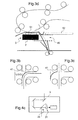
- a second solution, proposed by the applicant, and illustrated to figures 3a , 3b, 3c and 3d consists, not to move the optical module in front of the paper path, but to bring the printed sheet in front of the optical module.
- the solution is to deviate from the direct path 43 the printed sheet to pass in a path bis 42 passing in front of the optical sensor.
- the direct path of the printer 43 does not pass in front of the scanner to allow the possibility of using both devices simultaneously as described above.
- a mechanical switching system 40 makes it possible to take a path which then passes through the scanner.
- the switch is advantageously made by a piece of paper path retractable 41 in translation or in rotation by a micro actuator.
- the junction between the paper path of the printer and the scanner does not require any dynamic device given the direction of movement of the sheet.
- the sheet thus engaged in the scanner portion is digitized before being ejected optionally into the output receptacle of the scanner 54, or to be reintroduced into a return path in the printer to be ejected into the output receptacle of the scanner.
- an additional switch 40 illustrated in FIG. figure 3d is provided and a guide device allowing the sheet to pass through the area 45 in which must be able to freely translate the carriage 2.
- the present invention aims to overcome the aforementioned drawbacks and to propose a solution in which the optical sensor is fixed and shared between several mobile carriages or fixed points.
- the present invention proposes a dynamic optical length adjustment module as well as a carriage equipped with this module and a scanning device.
- multifunctional device equipped with at least one module intended to cooperate with an optical sensor of said device.
- the dynamic adjustment module comprises a first and a second series of mirrors (M1, M2) allowing the realization of an optical path between the object to be digitized and the optical sensor and adjustment means making it possible to reduce or to increase the optical path in the module.
- the structure of the carriage therefore makes it possible to maintain in real time a constant optical path length during its displacement and consequently allows the use of an optical sensor without a device for correcting the length of the optical path.
- the scanning carriage comprises n mirrors for each series of mirrors allowing the realization of N allers return of the optical path in the carriage 2.
- the choice of the number of mirrors constitutes a compromise, it must not be too much low that would require too much race of the two sets of mirrors, nor too big what would multiply a possible inaccuracy at the level of the spacing between the two sets of mirrors.
- the synchronization means comprise a coupling between the displacement means and the spacing means allowing a constant speed ratio N between the spacing speeds of the two series of mirrors and the displacement of the carriage.
- Another object of the present invention is to provide a multi-function scanning device with a fixed optical sensor, two scanning carriages and a mirror for scanning a document lying flat on both sides of the paper, a document coming from a document feeder. front and a document from a simplex printer.
- This architecture makes it possible in particular to compare for the same document, the document scanned from the original with a scanning of the printed document so as to automatically check for possible printing errors.
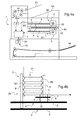
- a digitizing device 1 with two carriages 2, an optical sensor 3 is shown.
- Each carriage 2 comprises motorized displacement means 4 allowing the carriages 2 to move.
- the motorized displacement means 4 will comprise at least one toothed belt 5, a motor (not shown in the appended drawings) for driving said belt 5 and a fixed link between the belt 5 and the carriage 2.
- the carriage 2 comprises a dynamic adjustment module 20 with a first and a second series of mirrors respectively M1 and M2 and adjustment means 21.
- the optical path may also comprise one or more additional mirrors M3 as represented in the example of FIG. figure 4a to define an optical path to the optical sensor 3.
- n mirrors of the same series are arranged between them at a 45 ° angle.
- the mirrors of the same series being held by support elements 6.
- the adjustment means 21 comprise spacing means 7 for varying the distance between the two sets of mirrors M1 and M2. These spacing means 7 are advantageously connected to the support elements 6 and allow the displacement of a series of mirrors relative to each other in parallel planes. In the example of figures 1 and 2 the series of mirrors M1 is fixed with respect to the carriage 2 and only the series of mirrors M2 is mobile, driven by the spacer means 7.
- the modification of the spacing between the series of mirrors of M1 and M2 by a given distance 1 makes it possible to increase or decrease according to whether respectively the series of mirrors M1 and M2 deviate or are close to one another.
- the other the length of the optical path in the carriage 2 of a length proportional to 1 and the number of back and forth N between the two sets of mirrors M1 and M2.
- the number of round trips N will be between 5 and 15.
- the carriage 2 also comprises synchronization means 8 between the motorized displacement means 4 and the spacer means 7 making it possible to maintain a substantially constant optical path length regardless of the position of the carriage 2 on its path.
- the synchronization means 8 allow an action of the spacing means 7 generating a spacing between the two sets of mirrors M1 and M2 of length l / N so that the total length of the optical path remains constant.
- the synchronization means 8 allow an action of the spacing means 7 causing a reconciliation between the two series. mirrors M1 and M2 of a length 1 / N so that again the total length of the optical path remains constant.
- the synchronization means 8 comprise a coupling 9 between the displacement means 4 and the spacing means 7 allowing a constant speed ratio N between the spacing speeds of the two sets of mirrors. M1 and M2 and moving the carriage 2.
- the displacement means 4 and spacing 7 share a same engine
- the coupling 9 for synchronization comprising at least one pinion 10 connecting the drive belt 11 of the series of mirrors M2 to that of the carriage 2.
- the structure of the carriage 2 therefore makes it possible to maintain in real time a constant optical path length during its displacement and consequently allows the use of an optical sensor 3 without internal device for correcting the length of the optical path.
- the structure of the carriage 2 therefore makes it possible to imagine novel architectures at the level of the device digitization since it is possible to adjust all the carriages 2 on the same optical path length and thus to share an optical sensor 3 on all of the carriages 2 of the scanning device 1.
- the multi-input optical sensor is then simply a conventional optical sensor to which is added a conventional optical sextant type optical device for selecting the desired optical source; all the sources described in the device 1 already have the appropriate optical path length thanks to the adjustment devices described.
- this architecture allows new features and in particular allows for the same document to automatically perform a scanning of the original document, printing and scanning of the printed document so as to automatically check for any printing errors.
- the dynamic adjustment module 20 will not be integrated with the various carriages but with the optical sensor 3 as represented in FIG. figure 4c .
- adjustment means 21 are provided at the optical sensor 3, comprising bypass means 22 making it possible to reduce or increase the length of the optical path in the sensor to obtain a constant total optical path length. .
- This solution is particularly suitable in the case where the different sources to be aimed are already at the focusing distance of the fixed optical sensor.
Landscapes
- Engineering & Computer Science (AREA)
- Multimedia (AREA)
- Signal Processing (AREA)
- Facsimile Scanning Arrangements (AREA)
Applications Claiming Priority (1)
| Application Number | Priority Date | Filing Date | Title |
|---|---|---|---|
| FR0806773A FR2939210B1 (fr) | 2008-12-03 | 2008-12-03 | Module de reglage dynamique de la longueur d'un chemin optique, chariot, capteur optique et dispositif de numerisation multifonctions equipes d'au moins un module tel que precite |
Publications (2)
| Publication Number | Publication Date |
|---|---|
| EP2194701A2 true EP2194701A2 (de) | 2010-06-09 |
| EP2194701A3 EP2194701A3 (de) | 2011-12-21 |
Family
ID=40848040
Family Applications (1)
| Application Number | Title | Priority Date | Filing Date |
|---|---|---|---|
| EP09290873A Withdrawn EP2194701A3 (de) | 2008-12-03 | 2009-11-19 | Modul zur dynamischen Anpassung der Länge einer optischen Weglänge, optischer Sensor und digitales Multifunktions-Gerät mit mindestens einem solchen Modul |
Country Status (2)
| Country | Link |
|---|---|
| EP (1) | EP2194701A3 (de) |
| FR (1) | FR2939210B1 (de) |
Family Cites Families (6)
| Publication number | Priority date | Publication date | Assignee | Title |
|---|---|---|---|---|
| US5140443A (en) * | 1989-07-25 | 1992-08-18 | Victor Company Of Japan, Ltd. | Image scanning apparatus |
| JP3118016B2 (ja) * | 1990-07-06 | 2000-12-18 | 株式会社リコー | 画像読み取り装置 |
| DE69525715T2 (de) * | 1994-11-17 | 2002-08-22 | Nikon Corp., Tokio/Tokyo | Bildeingabevorrichtung |
| US5966221A (en) * | 1995-06-29 | 1999-10-12 | Agfa Corporation | Single lamp illumination system for a dual plane flat-bed scanner |
| JP4395951B2 (ja) * | 2000-01-13 | 2010-01-13 | コニカミノルタホールディングス株式会社 | 画像読取装置、およびそれを用いた画像形成装置 |
| JP2006115137A (ja) * | 2004-10-13 | 2006-04-27 | Nec Access Technica Ltd | 画像読取装置及び該画像読取装置における変倍方法 |
-
2008
- 2008-12-03 FR FR0806773A patent/FR2939210B1/fr not_active Expired - Fee Related
-
2009
- 2009-11-19 EP EP09290873A patent/EP2194701A3/de not_active Withdrawn
Also Published As
| Publication number | Publication date |
|---|---|
| FR2939210A1 (fr) | 2010-06-04 |
| EP2194701A3 (de) | 2011-12-21 |
| FR2939210B1 (fr) | 2011-04-22 |
Similar Documents
| Publication | Publication Date | Title |
|---|---|---|
| EP0006482B1 (de) | Schaltung zur Erkennung der Maxima und Minima eines elektrischen Signals variabler Amplitude und niedriger Frequenz sowie Verwendung dieser Schaltung, um bei zwei sich zueinander bewegenden Objekten Ausmass und Richtung der Bewegung zu bestimmen | |
| FR2706049A1 (fr) | Appareil d'enregistrement d'image. | |
| FR2536551A1 (fr) | Dispositif de balayage d'entree/sortie recurrent | |
| CH669271A5 (fr) | Procede pour stabiliser une image focalisee par un objectif photographique et dispositif pour la mise en oeuvre de ce procede. | |
| FR2728356A1 (fr) | Dispositif d'impression d'un reseau de bragg dans une fibre optique | |
| EP0616886A1 (de) | Vorrichtung zum nacheinander Bedrucken von Bogen und die korrespondierende Druckstrasse | |
| FR2589021A1 (fr) | Lecteur-enregistreur integre | |
| FR2647913A1 (fr) | Dispositif optique a reseau et element separateur pour le controle, par detection de phase, d'un quelconque systeme optique, en particulier d'une lentille ophtalmique | |
| FR2458824A1 (fr) | Mecanisme de reglage de l'ecartement interoculaire de jumelles | |
| FR2707768A1 (fr) | Appareil de formation d'image. | |
| BE1000092A7 (fr) | Analyse des particularites physiques d'objets de verre. | |
| EP4309074A1 (de) | Verfahren zur erfassung eines auf einer glasscheibe oder glaskeramik markierten codes und entsprechendes system | |
| FR3070635B1 (fr) | Palette tactile a effet optique sur volant de conduite pour detection de doigt | |
| EP2194701A2 (de) | Modul zur dynamischen Anpassung der Länge einer optischen Weglänge, optischer Sensor und digitales Multifunktions-Gerät mit mindestens einem solchen Modul | |
| EP3658869A2 (de) | Temperaturkompensationsvorrichtung und elektrooptischer transponder mit einer solchen vorrichtung | |
| EP3926416B1 (de) | Vorrichtung zur messung einer uhrwerkskomponente | |
| CH665722A5 (fr) | Appareil pour repositionner la lentille d'un copieur a grossissement variable. | |
| FR2496918A1 (fr) | Appareil de reprographie electrostatique | |
| FR2567286A1 (fr) | Dispositif d'analyse optique pour une machine de reprographie | |
| FR2786758A1 (fr) | Procede de mesure de l'epaisseur d'une feuille ou pile de feuilles et machine de traitement de feuilles mettant en oeuvre ce procede | |
| FR2558959A1 (fr) | Appareil de controle de surfaces d'objets | |
| EP2090398B1 (de) | Gerät zum Polieren von Glasfasern, die in einem Stecker angebracht sind | |
| EP0523305B1 (de) | Vorrichtung mit Planetrollen zum Behandeln von Wertpapieren wie Banknoten | |
| FR2548397A1 (fr) | Dispositif de changement d'agrandissement pour machine a copier | |
| FR2610421A1 (fr) | Dispositif de deflexion de faisceau et imprimante a faisceau laser l'utilisant |
Legal Events
| Date | Code | Title | Description |
|---|---|---|---|
| PUAI | Public reference made under article 153(3) epc to a published international application that has entered the european phase |
Free format text: ORIGINAL CODE: 0009012 |
|
| AK | Designated contracting states |
Kind code of ref document: A2 Designated state(s): AT BE BG CH CY CZ DE DK EE ES FI FR GB GR HR HU IE IS IT LI LT LU LV MC MK MT NL NO PL PT RO SE SI SK SM TR |
|
| AX | Request for extension of the european patent |
Extension state: AL BA RS |
|
| RAP1 | Party data changed (applicant data changed or rights of an application transferred) |
Owner name: SAGECOM DOCUMENTS SAS |
|
| RAP1 | Party data changed (applicant data changed or rights of an application transferred) |
Owner name: SAGEMCOM DOCUMENTS SAS |
|
| PUAL | Search report despatched |
Free format text: ORIGINAL CODE: 0009013 |
|
| AK | Designated contracting states |
Kind code of ref document: A3 Designated state(s): AT BE BG CH CY CZ DE DK EE ES FI FR GB GR HR HU IE IS IT LI LT LU LV MC MK MT NL NO PL PT RO SE SI SK SM TR |
|
| AX | Request for extension of the european patent |
Extension state: AL BA RS |
|
| RIC1 | Information provided on ipc code assigned before grant |
Ipc: H04N 1/04 20060101AFI20111111BHEP |
|
| 17P | Request for examination filed |
Effective date: 20120425 |
|
| 17Q | First examination report despatched |
Effective date: 20120704 |
|
| STAA | Information on the status of an ep patent application or granted ep patent |
Free format text: STATUS: THE APPLICATION IS DEEMED TO BE WITHDRAWN |
|
| 18D | Application deemed to be withdrawn |
Effective date: 20140821 |