EP2194693B1 - Dispositif électronique portable - Google Patents
Dispositif électronique portable Download PDFInfo
- Publication number
- EP2194693B1 EP2194693B1 EP09004834A EP09004834A EP2194693B1 EP 2194693 B1 EP2194693 B1 EP 2194693B1 EP 09004834 A EP09004834 A EP 09004834A EP 09004834 A EP09004834 A EP 09004834A EP 2194693 B1 EP2194693 B1 EP 2194693B1
- Authority
- EP
- European Patent Office
- Prior art keywords
- electronic device
- handheld electronic
- sliding block
- spread
- disposed
- Prior art date
- Legal status (The legal status is an assumption and is not a legal conclusion. Google has not performed a legal analysis and makes no representation as to the accuracy of the status listed.)
- Active
Links
- 230000007246 mechanism Effects 0.000 claims abstract description 76
- 238000010586 diagram Methods 0.000 description 18
- 238000000034 method Methods 0.000 description 18
- 238000005381 potential energy Methods 0.000 description 9
- 230000000694 effects Effects 0.000 description 2
- 238000004880 explosion Methods 0.000 description 2
- 230000003247 decreasing effect Effects 0.000 description 1
- 238000005516 engineering process Methods 0.000 description 1
- 238000011010 flushing procedure Methods 0.000 description 1
- 238000012905 input function Methods 0.000 description 1
- 230000002452 interceptive effect Effects 0.000 description 1
- 238000010327 methods by industry Methods 0.000 description 1
Images


Classifications
-
- H—ELECTRICITY
- H04—ELECTRIC COMMUNICATION TECHNIQUE
- H04M—TELEPHONIC COMMUNICATION
- H04M1/00—Substation equipment, e.g. for use by subscribers
- H04M1/02—Constructional features of telephone sets
- H04M1/0202—Portable telephone sets, e.g. cordless phones, mobile phones or bar type handsets
- H04M1/0206—Portable telephones comprising a plurality of mechanically joined movable body parts, e.g. hinged housings
- H04M1/0208—Portable telephones comprising a plurality of mechanically joined movable body parts, e.g. hinged housings characterized by the relative motions of the body parts
- H04M1/0235—Slidable or telescopic telephones, i.e. with a relative translation movement of the body parts; Telephones using a combination of translation and other relative motions of the body parts
- H04M1/0237—Sliding mechanism with one degree of freedom
-
- H—ELECTRICITY
- H04—ELECTRIC COMMUNICATION TECHNIQUE
- H04M—TELEPHONIC COMMUNICATION
- H04M1/00—Substation equipment, e.g. for use by subscribers
- H04M1/02—Constructional features of telephone sets
- H04M1/0202—Portable telephone sets, e.g. cordless phones, mobile phones or bar type handsets
- H04M1/0206—Portable telephones comprising a plurality of mechanically joined movable body parts, e.g. hinged housings
- H04M1/0208—Portable telephones comprising a plurality of mechanically joined movable body parts, e.g. hinged housings characterized by the relative motions of the body parts
- H04M1/0214—Foldable telephones, i.e. with body parts pivoting to an open position around an axis parallel to the plane they define in closed position
- H04M1/0216—Foldable in one direction, i.e. using a one degree of freedom hinge
- H04M1/022—The hinge comprising two parallel pivoting axes
Definitions
- the present application relates to a handheld electronic device. More particularly, the present application relates to a sliding handheld electronic device.
- the mobile phones can be generally classified into flip phones, twist phones and slide phones, etc.
- the slide phone an upper body and lower body thereof are stacked and are slidable relative to one another, so as to achieve different operation modes such as open and close, etc. Stacking of the two bodies avails miniaturizing a whole size of the slide phone, and the upper and lower bodies can be spread under a specific operation mode.
- the height step not only influences a whole appearance of the mobile phone, but also influences an operation convenience of a user. For example, to avoid an interference caused by the height step in use, a certain distance has to be kept between first row keys and the height step, so that maximization of a keyboard design cannot be achieved.
- US 2007/0243896 discloses an extendible mobile electronic device with a housing having a first housing element comprising a first front surface and a first rear surface and a second housing element, comprising a second front surface and a second rear surface. Said first housing element, and said second housing element are extensibly supported to each other, such that said first and second housing elements can adopt a retracted position and an extended position with respect to each other. In said retracted position said first housing element and said second housing element are located substantially on top of each other, said first rear surface conformingly adjoining said second front surface. In said extended position said first housing element is displaced with respect to said second housing element and at least a section of said second front surface is adjoining said and flushing with said first front surface.
- EP 1 796 351 A1 discloses a mobile terminal having a first body, a second body slidably attached to the first body, and means for connecting the first body to the second body and allowing the second body to be moved between a closed position and an open position such that an overall thickness of the mobile terminal in the open position is thinner than an overall thickness of the mobile terminal in the closed position.
- the means includes a slide mechanism having at least one rail mechanism attached to the first body; and at least one slider mechanism attached to the second body and slidably engaged with the at least one rail mechanism.
- the present application is directed to a handheld electronic device having two stacked bodies, in which upper surfaces of the two bodies can be spread to be coplanar.
- the present application provides a handheld electronic device including a first body, a second body, a sliding block and a linkage mechanism.
- the first body is stacked on the second body.
- the sliding block is located between the first body and the second body, and is slidably coupled to the first body.
- the linkage mechanism is connected between the sliding block and the second body to drive the sliding block moving relative to the second body, so that after the first body and the second body are spread along a direction, the first body and the second body are approximately coplanar.
- the sliding handheld electronic device may have a levelled appearance under a spread state, but also an operation convenience of a user can be improved.
- Fig. 1 is an explosion diagram illustrating a handheld electronic device according to an embodiment of the present invention.
- Figs. 2A-2E are diagrams illustrating a spread process of a handheld electronic device according to the embodiment of the present invention.
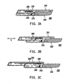
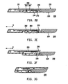
- Figs. 3A-3G are diagrams illustrating a spread and a close process of a handheld electronic device according to another embodiment of the present invention.
- Fig. 4 is a schematic diagram illustrating a handheld electronic device applying a lock mechanism of the present application.
- Fig. 5A and Fig. 5B are schematic diagrams illustrating operations of a lock mechanism of Fig. 4 .
- Fig. 6 is a schematic diagram illustrating a handheld electronic device applying a rotatable member of the present application.
- Fig. 7A and Fig. 7B are schematic diagrams illustrating operations of a rotatable member of Fig. 6 .
- Fig. 8 is a schematic diagram illustrating a spread vertical sliding handheld electronic device and a spread lateral sliding handheld electronic device of the present application.
- Fig. 9 is a schematic diagram illustrating a dual-screen sliding handheld electronic device of the present application.
- Fig. 1 is an explosion diagram illustrating a handheld electronic device according to an embodiment of the present invention.
- the handheld electronic device 100 includes a first body 110, a second body 120, a sliding block 130, a linkage mechanism 140 and a first elastic member 150.
- the first body 110 is stacked on the second body 120.
- the sliding block 130, the linkage mechanism 140 and the first elastic member 150 are disposed between the first body 110 and the second body 120, so that the first body 110 and the second body 120 can be relatively slid along a direction H to switch operation modes of spread state and close state.
- the first body 110 includes a first main body 112 and a first plate 114.
- the first main body 112 is disposed on the first plate 114, and the first plate 114 is slidably coupled to the sliding block 130, so that the first main body 112 can be moved along the direction H relative to the second body 120 through the sliding block 130.
- the first plate 114 can also be omitted, so that the sliding block 130 is directly combined to the first main body 112.
- the second body 120 includes a second main body 122 and a second plate 124.
- the linkage mechanism 140 is connected between the sliding block 130 and the second main body 122.
- the first body 110 and the second body 120 are spread along the direction H, the first body 110 is further moved relative to the second body 120 through the linkage mechanism 140, so that the first body 110 and the second body 120 can be coplanar (shown as Fig. 2E and Fig. 3D in the followings), and the first body 110 and the second body 120 are partially stacked.
- the linkage mechanism 140 of the present embodiment is a parallel four-bar mechanism including four mutually parallel rods 142. Two ends of each of the rod 142 are pivotally connected to the sliding block 130 and the second main body 122, respectively.
- the linkage mechanism 142 is rotated while taking a pivot between the rod 142 and the second main body 122 as a shaft, and accordingly drives the sliding block 130 moving relative to the second main body 122, so that the first body 110 and the second body 120 are coplanar after being spread.
- Figs. 2A-2E are diagrams sequentially illustrating an operation process of the handheld electronic device 100 from a close state to a spread state.
- Fig. 2A is a schematic diagram illustrating the handheld electronic device in the close state.
- the first elastic member 150 is disposed between the first body 110 and the sliding block 130 for providing energy to move the first body 110 during a spread or a close process of the handheld electronic device 100.
- the handheld electronic device 100 has a semi-auto sliding function.
- the opposite sides of the first body 110 and the second body 120 respectively have a mutually-matched concave, so that when the handheld electronic device 100 is in a totally close state, the first body 110 and the second body 120 can be mutually stacked and may have an integral appearance.
- the sliding block 130, the linkage mechanism 140 and the first elastic member 150 are in an initial state.
- the first elastic member 150 can be a torsion spring, a coil spring or other elastic members that can achieve the semi-auto sliding.
- the first elastic member 150 is a pair of torsion spring.
- the first body 110 when a user pushes the first body 110, the first body 110 is slid relative to the second body 120 along the direction H, and the first elastic member 150 starts to store an elastic potential energy.
- the first elastic member 150 releases the stored elastic potential energy and automatically drives the first body 110 towards a force-applying direction of the user.
- the handheld electronic device 100 is totally spread, and the first body 110 enters the lower place of the concave of the second body 120.
- a first upper plane 111 of the first body 110 and a second upper plane 121 of the second body 120 are in a coplanar state.
- a side edge where the first body 110 leans against the second body 120 in the concave has a tilt angle.
- the tilt angle is, for example, between 55 degrees to 75 degrees.
- the tilt angle is, for example, 65 degrees.
- the linkage mechanism 140 drives the block 130, so that the first body 110 is rotated relative to the second body 120.
- the first body 110 is slid relative to the sliding block 130.
- the first elastic member 150 stores an elastic potential energy.
- the user pushes the first body 110 to the threshold position, the first elastic member 150 releases the stored elastic potential energy to accomplish the remained operation process, so that the first body 110 and the second body 120 are recovered to a stacked state shown as Fig. 2A . Therefore, the handheld electronic device 100 can provide the semi-auto sliding function.
- torsion spring is applied to serve as the first elastic member 150
- other types of the spring such as a coil spring or other types of the elastic member can also be applied to achieve the semi-auto sliding function.
- a positioning mechanism such as a magnet, a latch mechanism or a hook, etc. (which are described later) can also be applied to limit relative positions of the first body 110 and the second body 120 under the spread state.
- Figs. 3A-3D are diagrams illustrating an operation process of a handheld electronic device from a close state to a spread state according to another embodiment of the present invention
- Figs. 3E-3G are diagrams illustrating an operation process of the handheld electronic device from the spread state to the close state.
- a second elastic member 270 is further configured between a second body 220 and a linkage mechanism 240 to provide energy required for rotating the linkage mechanism 142 during the spread and the close process of the handheld electronic device 200.
- a positioning mechanism 260 is further disposed between a first body 210 and the second body 220 to limit the relative positions of the first body 210 and the second body 220 after the first body 210 and the second body 220 are spread.
- the linkage mechanism 240 cannot be self-rotated to elevate the first body 210.
- the handheld electronic device 200 is changed to a bar-type handheld electronic device, and the user can directly perform the phone call, input data or watch multimedia information, etc. through the spread state handheld electronic device.
- the positioning mechanism 260 for example includes a first magnetic member 262 and a second magnetic member 264.
- the first magnetic member 262 is disposed on the first body 210
- the second magnetic member 264 is disposed on the second body 220.
- the first magnetic member 262 and the second magnetic member 264 are mutually magnetic attracted after the first body 210 and the second body 220 are spread, so as to limit the relative positions of the first body 210 and the second body 220.
- the positioning mechanism 260 can also be substituted by mechanisms such as the latch mechanism, the hook, etc., so as to limit the relative positions of the first body 210 and the second body 220 under the spread state.
- a detailed operation flow of the handheld electronic device 200 is as follows.
- Fig. 3A is a schematic diagram illustrating the handheld electronic device 200 in the close state.
- a first elastic member 250 is configured between the first body 210 and a sliding block 230 for providing energy to move the first body 210 during the close process of the handheld electronic device 200.
- the first elastic member 250 is a coil spring.
- the opposite sides of the first body 210 and the second body 220 respectively have a mutually-matched concave, so that when the handheld electronic device 200 is in a totally close state, the first body 210 and the second body 220 can be mutually stacked and may have an integral appearance.
- the sliding block 230, the linkage mechanism 240 and the first elastic member 250 are in the initial state.
- the first body 210 when the user pushes the first body 210, the first body 210 is slid relative to the second body 220 along the direction H, and the first elastic member 250 is drove by the first body 210 and is extended to store an elastic potential energy.
- the linkage mechanism 240 drives the block 230, so that the first body 210 is moved into a lower place of the concave on the second body 220.
- the handheld electronic device 200 may include the positioning mechanism 260 to fix the relative positions of the first body 210 and the second body 220.
- the linkage mechanism 240 cannot be self-rotated to elevate the first body 210. For example, when the user uses the first body 210 and the second body 220 in the spread state to perform the phone call, and if the first body 210 is touched to the user's ear, a relative movement between the first body 210 and the second body 220 is prevented.
- the positioning mechanism 260 includes the first magnetic member 262 and the second magnetic member 264 respectively disposed in the first body 210 and the second body 220.
- the first magnetic member 262 and the second magnetic member 264 are mutually magnetic attracted to fix the relative positions of the first body 210 and the second body 220.
- the positioning mechanism 260 can also be substituted by mechanisms such as the latch mechanism, the hook, etc., so as to limit the relative positions of the first body 210 and the second body 220 under the spread state of the handheld electronic device.
- the second elastic member 270 is configured between the linkage mechanism 240 and the second body 220. After the first body enters the lower place of the concave of the second body 220, the second elastic member 270 is compressed to store an elastic potential energy.
- Figs. 3E-3G are diagrams illustrating an operation process of the handheld electronic device 200 from the spread state to the close state.
- the user spreads the first body 210 and the second body 220 along the direction H to stagger the relative positions of the first magnetic member 262 and the second magnetic member 264, so as to release a position-limiting effect of the first magnetic member 262 and the second magnetic member 264 to the first body 210 and the second body 220.
- the positioning mechanism 260 is the latch mechanism, or the hook, etc., the position-limiting effect of the latch mechanism or the hook can also be released when the user spreads the first body 210 and the second body 220 along the direction H.
- the side edge where the first body 210 leans against the second body 120 in the concave doesn't have any limitations due to the first body 210 can be put out.
- the tilt angle as described in the previous embodiment is not limited between 55 degrees to 75 degrees, and the side edge of the first body 210 can be any shape since the first body 210 can be put out.
- the second elastic member 270 releases the stored elastic potential energy to rotate the linkage mechanism 240, so that the bottom surface of the first body 210 is higher than the second body 220.
- the stored elastic potential energy released by the first elastic member 250 drives the first body 210 to move along the direction H, so as to achieve the close state of the handheld electronic device 200 shown in Fig. 3G .
- the handheld electronic device 100 may include a lock mechanism 144 disposed on the linkage mechanism 140.
- the lock mechanism 144 can drive a rotation of the linkage mechanism 140 to elevate the sliding block 130, so that a position of the sliding block 130 can be higher than that of the lock mechanism 144. Then, the first body 110 is moved along the direction H and passes over the lock mechanism to achieve the close state.
- Fig. 5A and Fig. 5B are schematic diagrams illustrating operations of the lock mechanism 144.
- the user pushes the first body 110 to move along the direction H.
- the position of the sliding block 130 is higher that of the lock mechanism 144.
- the first body 110 can be moved by the elastic potential energy stored in the first elastic member 150, so as to achieve the close state of the first body 110 and the second body 120.
- a rotatable member 126 is further configured between the first body 110 and the second body 120.
- the first body 110 is omitted in Fig. 6 .
- Fig. 7A and Fig. 7B are diagrams illustrating operations of the rotatable member.
- Fig. 7A after the handheld electronic device 100 is spread, a short edge of the first body 110 is leaned against the rotatable member 126, and the rotatable member 126 is pivotally disposed on the second body 120 along a rotation shaft 126a.
- Fig. 7B during the close process of the handheld electronic device 100, the rotatable member 126 rotates along the rotation shaft 126a, so that the first body 110 can smoothly overpass the concave of the second body 120, so as to avoid the interference between the first body 110 and the second body 120 that influences an operation feeling of the user.
- the rotatable member 126, the lock mechanism 144, the second elastic member 270 and the positioning mechanism 260 are not limited to the aforementioned embodiments, and combinations and variations of the devices can be made within reasonable range and design, so as to match actual requirements.
- the positioning mechanism 260 can be used for fixing the relative positions of the first body 110 and the second body 120, and application of the lock mechanism 144, the rotatable member 126 and the second elastic member 270 can smooth the close process of the first body 110.
- the relative movement direction of the first body 110 and the second body 120 is not limited to be along the direction of a long-axis A-A' of the handheld electronic device.
- the relative movement direction of the first body 110 and the second body 120 can be changed to be perpendicular to the direction of the long-axis A-A' of the handheld electronic device, so that the present invention can not only be applied to vertical sliding handheld electronic devices, but can also be applied to lateral sliding handheld electronic devices.
- the first body 110 has a first display interface 113, and the first display interface 113 can be a display or a touch screen.
- the second body 120 has an input interface 125, and the input interface 125 can be a keyboard, a touch keyboard or a touch screen.
- the first body 110 has the first display interface 113
- the second body 120 has a second display interface 123
- the first display interface 113 can be a display or a touch screen
- the second display interface 123 can be a touch screen.
- a control key 160 can be formed there between.
- the first body 110 and the second body 120 respectively comprise a part of the control key.
- a touch screen can be formed between the first body 110 and the second body 120. Therefore, patterns of the first body 110 and the second body 120 are not limited to the aforementioned descriptions, and combinations and variations thereof can be made within reasonable range, so as to match the actual requirements.
- the first body 110 or the second body 120 can respectively comprise the display interface and the input interface, or a touch panel can be applied to simultaneously provide a display function and an information input function.
- the sliding block and linkage mechanism are applied to meliorate a conventional sliding handheld electronic device having a concave in the spread state.
- the first and the second bodies are meliorated to be coplanar after being spread, and are partially stacked to contain the sliding block and the linkage mechanism, so as to improve a usage area of the sliding handheld electronic device.
- the present invention can further be applied to the vertical sliding handheld electronic devices and the lateral sliding handheld electronic device.
- the elastic member, the positioning mechanism, the lock mechanism and the rotatable member, etc. can be applied to improve a design flexibility, so as to match different design requirements.
- the first body may include the display interface
- the second body may include the keyboard.
- the first body and the second body man all include the touch screen, so that the first display interface 113 and the second display interface 123 may have an interactive function.
- application of the present invention is not limited to the vertical sliding handheld electronic devices, but is also adapted to the lateral sliding handheld electronic devices, so that the application and usage convenience of the present invention can be expended.
Claims (11)
- Dispositif électronique portatif, comprenant:un premier corps (110, 210) ;un deuxième corps (120, 220), dans lequel le premier corps (110, 210) est empilé sur le deuxième corps (120, 220), et un côté du deuxième corps (120, 220) faisant face au premier corps (110, 210) a un palier ;un bloc coulissant (130, 230), situé entre le premier corps (110, 210) et le deuxième corps (120, 220), et couplé de manière à pouvoir coulisser au premier corps (110, 210) ; etun mécanisme de liaison (140, 240), relié entre le bloc coulissant (130, 230) et le deuxième corps (120, 220) pour entraîner le bloc coulissant (130, 230) se déplaçant par rapport au deuxième corps (120, 220), dans lequel le dispositif électronique portatif est caractérisé en ce qu'il comprend en outre:un premier élément élastique (150, 250), disposé entre le premier corps (110, 210) et le bloc coulissant (130, 230),un deuxième élément élastique (270), disposé entre le deuxième corps (120, 220) et le mécanisme de liaison (140, 240) ;un mécanisme de positionnement (260), disposé entre le premier corps (110, 210) et le deuxième corps (120, 220) ;dans lequel pour recevoir un état déployé du dispositif électronique portatif, le premier corps (110, 210) et le deuxième corps (120, 220) sont aptes à se déployer dans une direction, le premier corps (110, 210) est apte à entrer dans un emplacement inférieur du palier, afin qu'une surface supérieure du premier corps (110, 210) et une surface supérieure du deuxième corps (120, 220) soient approximativement coplanaires, et les premier et deuxième éléments élastiques (150, 250, 270) sont aptes à stocker une énergie élastique,et pour recevoir un état fermé du dispositif électronique portatif, le premier corps (110, 210) etle deuxième corps (120, 220) sont aptes à se déployer dans la même direction sur une distance supplémentaire, dans lequel le premier élément élastique (150, 250) libère l'énergie élastique stockée pour rétracter le premier corps (110, 210) etle deuxième corps (120, 220) et le deuxième élément élastique (270) libère l'énergie élastique stockée pour faire tourner le mécanisme de liaison (140, 240).
- Dispositif électronique portatif selon la revendication 1, dans lequel le mécanisme de liaison (140, 240) est un mécanisme à quatre barres parallèles comprenant quatre tiges parallèles, et deux extrémités de chaque tige sont reliées de manière à pouvoir pivoter respectivement au bloc coulissant (130, 230) et au deuxième corps (120, 220).
- Dispositif électronique portatif selon la revendication 1, dans lequel le premier élément élastique (150, 250) comprend un ressort de torsion ou un ressort hélicoïdal.
- Dispositif électronique portatif selon la revendication 1, dans lequel le mécanisme de positionnement comprend un premier élément magnétique et un deuxième élément magnétique disposés respectivement sur le premier corps (110, 210) et le deuxième corps (120, 220), dans lequel le premier élément magnétique et le deuxième élément magnétique sont mutuellement attirés magnétiquement après le déploiement du premier corps (110, 210) et du deuxième corps (120, 220).
- Dispositif électronique portatif selon la revendication 1, comprenant en outre un mécanisme de verrouillage disposé sur le mécanisme de liaison (140, 240), et le mécanisme de verrouillage s'appuyant contre le bloc coulissant (130, 230) après le déploiement du premier corps (110, 210) et du deuxième corps (120, 220).
- Dispositif électronique portatif selon la revendication 1, comprenant en outre un élément rotatif disposé à une jonction du premier corps (110, 210) et du deuxième corps (120, 220), dans lequel l'élément rotatif est disposé de manière à pouvoir pivoter sur le deuxième corps (120, 220) et s'appuie contre le premier corps (110, 210), et il est tourné avec un mouvement relatif du premier corps (110, 210) et du deuxième corps (120, 220).
- Dispositif électronique portatif selon la revendication 1, dans lequel le premier corps (110, 210) et le deuxième corps (120, 220) ont respectivement une direction d'axe long, et les directions d'axe long du premier corps (110, 210) et du deuxième corps (120, 220) sont respectivement parallèles à la direction.
- Dispositif électronique portatif selon la revendication 1, dans lequel le premier corps (110, 210) et le deuxième corps (120, 220) ont respectivement une direction d'axe long, et les directions d'axe long du premier corps (110, 210) et du deuxième corps (120, 220) sont respectivement perpendiculaires à la direction.
- Dispositif électronique portatif selon la revendication 1, dans lequel un côté du premier corps (110, 210) à l'opposé du bloc coulissant (130, 230) a une première interface d'affichage.
- Dispositif électronique portatif selon la revendication 9, dans lequel un côté du deuxième corps (120, 220) face au bloc coulissant (130, 230) a une interface d'entrée, et l'interface d'entrée est exposée lorsque le premier corps (110, 210) et le deuxième corps (120, 220) sont déployés.
- Dispositif électronique portatif selon la revendication 9, dans lequel un côté du deuxième corps (120, 220) face au bloc coulissant (130, 230) a une deuxième interface d'affichage, et la deuxième interface d'affichage est exposée lorsque le premier corps (110, 210) et le deuxième corps (120, 220) sont déployés.
Applications Claiming Priority (1)
| Application Number | Priority Date | Filing Date | Title |
|---|---|---|---|
| TW097147399A TWI372552B (en) | 2008-12-05 | 2008-12-05 | Handheld electronic device |
Publications (2)
| Publication Number | Publication Date |
|---|---|
| EP2194693A1 EP2194693A1 (fr) | 2010-06-09 |
| EP2194693B1 true EP2194693B1 (fr) | 2011-11-16 |
Family
ID=40756298
Family Applications (1)
| Application Number | Title | Priority Date | Filing Date |
|---|---|---|---|
| EP09004834A Active EP2194693B1 (fr) | 2008-12-05 | 2009-04-01 | Dispositif électronique portable |
Country Status (4)
| Country | Link |
|---|---|
| US (1) | US8140135B2 (fr) |
| EP (1) | EP2194693B1 (fr) |
| AT (1) | ATE534230T1 (fr) |
| TW (1) | TWI372552B (fr) |
Families Citing this family (17)
| Publication number | Priority date | Publication date | Assignee | Title |
|---|---|---|---|---|
| TWI362209B (en) * | 2008-10-08 | 2012-04-11 | Htc Corp | Portable electronic device |
| US9052874B2 (en) * | 2008-11-14 | 2015-06-09 | Nokia Technologies Oy | Handheld device with a user interface |
| CN101753647A (zh) * | 2008-12-22 | 2010-06-23 | 鸿富锦精密工业(深圳)有限公司 | 分体式手机 |
| US8121661B2 (en) * | 2009-03-03 | 2012-02-21 | Sony Ericsson Mobile Communications Ab | Mechanism for radio communication terminal |
| US8948824B2 (en) * | 2009-08-05 | 2015-02-03 | Apple Inc. | Electronic devices with clips |
| CN102123568A (zh) * | 2010-01-07 | 2011-07-13 | 深圳富泰宏精密工业有限公司 | 滑动机构及应用该滑动机构的便携式电子装置 |
| US8374658B2 (en) | 2010-04-26 | 2013-02-12 | Nokia Corporation | Method and apparatus for flat and tilt slide mechanism |
| TWI376928B (en) | 2010-07-29 | 2012-11-11 | Htc Corp | Handheld electronic device |
| TWI426766B (zh) * | 2010-07-30 | 2014-02-11 | Htc Corp | 手持電子裝置 |
| KR101792502B1 (ko) * | 2010-08-12 | 2017-11-02 | 엘지전자 주식회사 | 이동 단말기 |
| TWI423186B (zh) * | 2010-12-31 | 2014-01-11 | Giga Byte Tech Co Ltd | 卸換裝置 |
| US8611973B2 (en) * | 2011-03-07 | 2013-12-17 | Blackberry Limited | Slidable portable electronic device with keypad portion adapted for covering display |
| CN102892262B (zh) * | 2011-07-21 | 2015-03-11 | 鸿富锦精密工业(深圳)有限公司 | 便携式电子装置 |
| TWI488571B (zh) | 2011-08-19 | 2015-06-11 | Au Optronics Corp | 手持電子裝置 |
| TWI511643B (zh) * | 2012-08-07 | 2015-12-01 | Wistron Corp | 可攜式電腦 |
| JP2015180113A (ja) * | 2015-06-30 | 2015-10-08 | 三菱製鋼株式会社 | 開閉装置 |
| TWI612412B (zh) * | 2017-02-22 | 2018-01-21 | 啓碁科技股份有限公司 | 免持電子裝置 |
Family Cites Families (4)
| Publication number | Priority date | Publication date | Assignee | Title |
|---|---|---|---|---|
| KR100631897B1 (ko) * | 2005-01-19 | 2006-10-11 | 삼성전기주식회사 | 경사 개폐 방식 이동통신단말기 |
| US9203938B2 (en) * | 2005-04-06 | 2015-12-01 | Nokia Technologies Oy | Extensible mobile electronic device |
| EP1796351B1 (fr) | 2005-12-12 | 2016-10-19 | LG Electronics Inc. | Terminal mobile de télécommunication de type coulissant |
| US7627337B2 (en) * | 2006-04-17 | 2009-12-01 | Nokia Corporation | Dual lever slide mechanism for extendible device housings |
-
2008
- 2008-12-05 TW TW097147399A patent/TWI372552B/zh active
-
2009
- 2009-03-18 US US12/406,126 patent/US8140135B2/en active Active
- 2009-04-01 EP EP09004834A patent/EP2194693B1/fr active Active
- 2009-04-01 AT AT09004834T patent/ATE534230T1/de active
Also Published As
| Publication number | Publication date |
|---|---|
| TWI372552B (en) | 2012-09-11 |
| TW201023594A (en) | 2010-06-16 |
| US20100144408A1 (en) | 2010-06-10 |
| US8140135B2 (en) | 2012-03-20 |
| ATE534230T1 (de) | 2011-12-15 |
| EP2194693A1 (fr) | 2010-06-09 |
Similar Documents
| Publication | Publication Date | Title |
|---|---|---|
| EP2194693B1 (fr) | Dispositif électronique portable | |
| EP3206379B1 (fr) | Dispositif électronique portatif | |
| EP1867143B1 (fr) | Dispositif electronique mobile extensible | |
| US7197346B2 (en) | Mobile electronic device having pivotable display element | |
| US7653422B2 (en) | Method and apparatus for a sliding hinge | |
| US8200300B2 (en) | Sliding electronic device | |
| US8180417B2 (en) | Portable terminal | |
| US20140049888A1 (en) | Portable communication device and cradle apparatus thereof | |
| KR101048031B1 (ko) | 휴대 전자기기 | |
| EP2285074B1 (fr) | Dispositif électronique portable et mécanisme montant | |
| JP2011515929A (ja) | スライダ兼フリップヒンジ組み立て体を有する携帯通信装置 | |
| US8797730B2 (en) | Sliding module for electronic device | |
| KR20090129647A (ko) | 슬라이딩 장치 및 이를 갖는 슬라이드형 휴대용 정보기기 | |
| JP5733311B2 (ja) | スライド機構、及び携帯機器 | |
| KR101000000B1 (ko) | 힌지장치 및 이를 이용한 휴대 단말기 | |
| JP4667622B2 (ja) | 移送機構および表示装置 | |
| KR101144133B1 (ko) | 스플릿 키패드가 구비된 휴대단말기 | |
| KR101264732B1 (ko) | 다중 개폐 가능한 개인휴대단말기 | |
| KR101310211B1 (ko) | 틸팅 가능한 개인휴대단말기 | |
| KR101351488B1 (ko) | 이동통신단말기 | |
| KR101007846B1 (ko) | 힌지 모듈 및 이를 이용한 이동통신 단말기 | |
| KR20120047504A (ko) | 이동통신 단말기용 힌지장치 | |
| KR100874765B1 (ko) | 회전과 슬라이딩이 가능한 일체형 휴대폰의 결합장치 | |
| KR20120136616A (ko) | 다중 개폐 가능한 개인휴대단말기 | |
| KR20070002727A (ko) | 2-방향 반자동 슬라이드 모듈 및 개인휴대단말기 |
Legal Events
| Date | Code | Title | Description |
|---|---|---|---|
| PUAI | Public reference made under article 153(3) epc to a published international application that has entered the european phase |
Free format text: ORIGINAL CODE: 0009012 |
|
| 17P | Request for examination filed |
Effective date: 20090402 |
|
| AK | Designated contracting states |
Kind code of ref document: A1 Designated state(s): AT BE BG CH CY CZ DE DK EE ES FI FR GB GR HR HU IE IS IT LI LT LU LV MC MK MT NL NO PL PT RO SE SI SK TR |
|
| AX | Request for extension of the european patent |
Extension state: AL BA RS |
|
| 17Q | First examination report despatched |
Effective date: 20100915 |
|
| RIC1 | Information provided on ipc code assigned before grant |
Ipc: H04M 1/02 20060101AFI20110606BHEP |
|
| GRAP | Despatch of communication of intention to grant a patent |
Free format text: ORIGINAL CODE: EPIDOSNIGR1 |
|
| GRAS | Grant fee paid |
Free format text: ORIGINAL CODE: EPIDOSNIGR3 |
|
| GRAA | (expected) grant |
Free format text: ORIGINAL CODE: 0009210 |
|
| AK | Designated contracting states |
Kind code of ref document: B1 Designated state(s): AT BE BG CH CY CZ DE DK EE ES FI FR GB GR HR HU IE IS IT LI LT LU LV MC MK MT NL NO PL PT RO SE SI SK TR |
|
| REG | Reference to a national code |
Ref country code: GB Ref legal event code: FG4D |
|
| REG | Reference to a national code |
Ref country code: CH Ref legal event code: EP |
|
| REG | Reference to a national code |
Ref country code: IE Ref legal event code: FG4D |
|
| REG | Reference to a national code |
Ref country code: DE Ref legal event code: R096 Ref document number: 602009003661 Country of ref document: DE Effective date: 20120112 |
|
| REG | Reference to a national code |
Ref country code: NL Ref legal event code: T3 |
|
| LTIE | Lt: invalidation of european patent or patent extension |
Effective date: 20111116 |
|
| PG25 | Lapsed in a contracting state [announced via postgrant information from national office to epo] |
Ref country code: LT Free format text: LAPSE BECAUSE OF FAILURE TO SUBMIT A TRANSLATION OF THE DESCRIPTION OR TO PAY THE FEE WITHIN THE PRESCRIBED TIME-LIMIT Effective date: 20111116 Ref country code: NO Free format text: LAPSE BECAUSE OF FAILURE TO SUBMIT A TRANSLATION OF THE DESCRIPTION OR TO PAY THE FEE WITHIN THE PRESCRIBED TIME-LIMIT Effective date: 20120216 Ref country code: IS Free format text: LAPSE BECAUSE OF FAILURE TO SUBMIT A TRANSLATION OF THE DESCRIPTION OR TO PAY THE FEE WITHIN THE PRESCRIBED TIME-LIMIT Effective date: 20120316 |
|
| PG25 | Lapsed in a contracting state [announced via postgrant information from national office to epo] |
Ref country code: LV Free format text: LAPSE BECAUSE OF FAILURE TO SUBMIT A TRANSLATION OF THE DESCRIPTION OR TO PAY THE FEE WITHIN THE PRESCRIBED TIME-LIMIT Effective date: 20111116 Ref country code: SE Free format text: LAPSE BECAUSE OF FAILURE TO SUBMIT A TRANSLATION OF THE DESCRIPTION OR TO PAY THE FEE WITHIN THE PRESCRIBED TIME-LIMIT Effective date: 20111116 Ref country code: PL Free format text: LAPSE BECAUSE OF FAILURE TO SUBMIT A TRANSLATION OF THE DESCRIPTION OR TO PAY THE FEE WITHIN THE PRESCRIBED TIME-LIMIT Effective date: 20111116 Ref country code: BE Free format text: LAPSE BECAUSE OF FAILURE TO SUBMIT A TRANSLATION OF THE DESCRIPTION OR TO PAY THE FEE WITHIN THE PRESCRIBED TIME-LIMIT Effective date: 20111116 Ref country code: PT Free format text: LAPSE BECAUSE OF FAILURE TO SUBMIT A TRANSLATION OF THE DESCRIPTION OR TO PAY THE FEE WITHIN THE PRESCRIBED TIME-LIMIT Effective date: 20120316 Ref country code: GR Free format text: LAPSE BECAUSE OF FAILURE TO SUBMIT A TRANSLATION OF THE DESCRIPTION OR TO PAY THE FEE WITHIN THE PRESCRIBED TIME-LIMIT Effective date: 20120217 Ref country code: HR Free format text: LAPSE BECAUSE OF FAILURE TO SUBMIT A TRANSLATION OF THE DESCRIPTION OR TO PAY THE FEE WITHIN THE PRESCRIBED TIME-LIMIT Effective date: 20111116 Ref country code: SI Free format text: LAPSE BECAUSE OF FAILURE TO SUBMIT A TRANSLATION OF THE DESCRIPTION OR TO PAY THE FEE WITHIN THE PRESCRIBED TIME-LIMIT Effective date: 20111116 |
|
| PG25 | Lapsed in a contracting state [announced via postgrant information from national office to epo] |
Ref country code: CY Free format text: LAPSE BECAUSE OF FAILURE TO SUBMIT A TRANSLATION OF THE DESCRIPTION OR TO PAY THE FEE WITHIN THE PRESCRIBED TIME-LIMIT Effective date: 20111116 |
|
| PG25 | Lapsed in a contracting state [announced via postgrant information from national office to epo] |
Ref country code: BG Free format text: LAPSE BECAUSE OF FAILURE TO SUBMIT A TRANSLATION OF THE DESCRIPTION OR TO PAY THE FEE WITHIN THE PRESCRIBED TIME-LIMIT Effective date: 20120216 Ref country code: CZ Free format text: LAPSE BECAUSE OF FAILURE TO SUBMIT A TRANSLATION OF THE DESCRIPTION OR TO PAY THE FEE WITHIN THE PRESCRIBED TIME-LIMIT Effective date: 20111116 Ref country code: DK Free format text: LAPSE BECAUSE OF FAILURE TO SUBMIT A TRANSLATION OF THE DESCRIPTION OR TO PAY THE FEE WITHIN THE PRESCRIBED TIME-LIMIT Effective date: 20111116 Ref country code: SK Free format text: LAPSE BECAUSE OF FAILURE TO SUBMIT A TRANSLATION OF THE DESCRIPTION OR TO PAY THE FEE WITHIN THE PRESCRIBED TIME-LIMIT Effective date: 20111116 Ref country code: EE Free format text: LAPSE BECAUSE OF FAILURE TO SUBMIT A TRANSLATION OF THE DESCRIPTION OR TO PAY THE FEE WITHIN THE PRESCRIBED TIME-LIMIT Effective date: 20111116 |
|
| PG25 | Lapsed in a contracting state [announced via postgrant information from national office to epo] |
Ref country code: IT Free format text: LAPSE BECAUSE OF FAILURE TO SUBMIT A TRANSLATION OF THE DESCRIPTION OR TO PAY THE FEE WITHIN THE PRESCRIBED TIME-LIMIT Effective date: 20111116 Ref country code: RO Free format text: LAPSE BECAUSE OF FAILURE TO SUBMIT A TRANSLATION OF THE DESCRIPTION OR TO PAY THE FEE WITHIN THE PRESCRIBED TIME-LIMIT Effective date: 20111116 |
|
| REG | Reference to a national code |
Ref country code: AT Ref legal event code: MK05 Ref document number: 534230 Country of ref document: AT Kind code of ref document: T Effective date: 20111116 |
|
| PLBE | No opposition filed within time limit |
Free format text: ORIGINAL CODE: 0009261 |
|
| STAA | Information on the status of an ep patent application or granted ep patent |
Free format text: STATUS: NO OPPOSITION FILED WITHIN TIME LIMIT |
|
| 26N | No opposition filed |
Effective date: 20120817 |
|
| PG25 | Lapsed in a contracting state [announced via postgrant information from national office to epo] |
Ref country code: MC Free format text: LAPSE BECAUSE OF NON-PAYMENT OF DUE FEES Effective date: 20120430 |
|
| REG | Reference to a national code |
Ref country code: DE Ref legal event code: R097 Ref document number: 602009003661 Country of ref document: DE Effective date: 20120817 |
|
| REG | Reference to a national code |
Ref country code: IE Ref legal event code: MM4A |
|
| PG25 | Lapsed in a contracting state [announced via postgrant information from national office to epo] |
Ref country code: IE Free format text: LAPSE BECAUSE OF NON-PAYMENT OF DUE FEES Effective date: 20120401 Ref country code: AT Free format text: LAPSE BECAUSE OF FAILURE TO SUBMIT A TRANSLATION OF THE DESCRIPTION OR TO PAY THE FEE WITHIN THE PRESCRIBED TIME-LIMIT Effective date: 20111116 |
|
| PG25 | Lapsed in a contracting state [announced via postgrant information from national office to epo] |
Ref country code: MK Free format text: LAPSE BECAUSE OF FAILURE TO SUBMIT A TRANSLATION OF THE DESCRIPTION OR TO PAY THE FEE WITHIN THE PRESCRIBED TIME-LIMIT Effective date: 20111116 |
|
| PG25 | Lapsed in a contracting state [announced via postgrant information from national office to epo] |
Ref country code: ES Free format text: LAPSE BECAUSE OF FAILURE TO SUBMIT A TRANSLATION OF THE DESCRIPTION OR TO PAY THE FEE WITHIN THE PRESCRIBED TIME-LIMIT Effective date: 20120227 |
|
| PG25 | Lapsed in a contracting state [announced via postgrant information from national office to epo] |
Ref country code: FI Free format text: LAPSE BECAUSE OF FAILURE TO SUBMIT A TRANSLATION OF THE DESCRIPTION OR TO PAY THE FEE WITHIN THE PRESCRIBED TIME-LIMIT Effective date: 20111116 |
|
| PG25 | Lapsed in a contracting state [announced via postgrant information from national office to epo] |
Ref country code: MT Free format text: LAPSE BECAUSE OF FAILURE TO SUBMIT A TRANSLATION OF THE DESCRIPTION OR TO PAY THE FEE WITHIN THE PRESCRIBED TIME-LIMIT Effective date: 20111116 |
|
| REG | Reference to a national code |
Ref country code: CH Ref legal event code: PL |
|
| PG25 | Lapsed in a contracting state [announced via postgrant information from national office to epo] |
Ref country code: LI Free format text: LAPSE BECAUSE OF NON-PAYMENT OF DUE FEES Effective date: 20130430 Ref country code: CH Free format text: LAPSE BECAUSE OF NON-PAYMENT OF DUE FEES Effective date: 20130430 |
|
| PG25 | Lapsed in a contracting state [announced via postgrant information from national office to epo] |
Ref country code: TR Free format text: LAPSE BECAUSE OF FAILURE TO SUBMIT A TRANSLATION OF THE DESCRIPTION OR TO PAY THE FEE WITHIN THE PRESCRIBED TIME-LIMIT Effective date: 20111116 |
|
| PG25 | Lapsed in a contracting state [announced via postgrant information from national office to epo] |
Ref country code: LU Free format text: LAPSE BECAUSE OF NON-PAYMENT OF DUE FEES Effective date: 20120401 |
|
| PG25 | Lapsed in a contracting state [announced via postgrant information from national office to epo] |
Ref country code: HU Free format text: LAPSE BECAUSE OF FAILURE TO SUBMIT A TRANSLATION OF THE DESCRIPTION OR TO PAY THE FEE WITHIN THE PRESCRIBED TIME-LIMIT Effective date: 20090401 |
|
| REG | Reference to a national code |
Ref country code: FR Ref legal event code: PLFP Year of fee payment: 7 |
|
| REG | Reference to a national code |
Ref country code: FR Ref legal event code: PLFP Year of fee payment: 8 |
|
| REG | Reference to a national code |
Ref country code: FR Ref legal event code: PLFP Year of fee payment: 9 |
|
| REG | Reference to a national code |
Ref country code: FR Ref legal event code: PLFP Year of fee payment: 10 |
|
| PGFP | Annual fee paid to national office [announced via postgrant information from national office to epo] |
Ref country code: FR Payment date: 20230309 Year of fee payment: 15 |
|
| PGFP | Annual fee paid to national office [announced via postgrant information from national office to epo] |
Ref country code: GB Payment date: 20230302 Year of fee payment: 15 |
|
| PGFP | Annual fee paid to national office [announced via postgrant information from national office to epo] |
Ref country code: NL Payment date: 20230314 Year of fee payment: 15 |
|
| P01 | Opt-out of the competence of the unified patent court (upc) registered |
Effective date: 20230602 |
|
| PGFP | Annual fee paid to national office [announced via postgrant information from national office to epo] |
Ref country code: DE Payment date: 20230307 Year of fee payment: 15 |
|
| PGFP | Annual fee paid to national office [announced via postgrant information from national office to epo] |
Ref country code: NL Payment date: 20240315 Year of fee payment: 16 |