EP2194693B1 - Handheld electronic device - Google Patents
Handheld electronic device Download PDFInfo
- Publication number
- EP2194693B1 EP2194693B1 EP09004834A EP09004834A EP2194693B1 EP 2194693 B1 EP2194693 B1 EP 2194693B1 EP 09004834 A EP09004834 A EP 09004834A EP 09004834 A EP09004834 A EP 09004834A EP 2194693 B1 EP2194693 B1 EP 2194693B1
- Authority
- EP
- European Patent Office
- Prior art keywords
- electronic device
- handheld electronic
- sliding block
- spread
- disposed
- Prior art date
- Legal status (The legal status is an assumption and is not a legal conclusion. Google has not performed a legal analysis and makes no representation as to the accuracy of the status listed.)
- Active
Links
Images


Classifications
-
- H—ELECTRICITY
- H04—ELECTRIC COMMUNICATION TECHNIQUE
- H04M—TELEPHONIC COMMUNICATION
- H04M1/00—Substation equipment, e.g. for use by subscribers
- H04M1/02—Constructional features of telephone sets
- H04M1/0202—Portable telephone sets, e.g. cordless phones, mobile phones or bar type handsets
- H04M1/0206—Portable telephones comprising a plurality of mechanically joined movable body parts, e.g. hinged housings
- H04M1/0208—Portable telephones comprising a plurality of mechanically joined movable body parts, e.g. hinged housings characterized by the relative motions of the body parts
- H04M1/0235—Slidable or telescopic telephones, i.e. with a relative translation movement of the body parts; Telephones using a combination of translation and other relative motions of the body parts
- H04M1/0237—Sliding mechanism with one degree of freedom
-
- H—ELECTRICITY
- H04—ELECTRIC COMMUNICATION TECHNIQUE
- H04M—TELEPHONIC COMMUNICATION
- H04M1/00—Substation equipment, e.g. for use by subscribers
- H04M1/02—Constructional features of telephone sets
- H04M1/0202—Portable telephone sets, e.g. cordless phones, mobile phones or bar type handsets
- H04M1/0206—Portable telephones comprising a plurality of mechanically joined movable body parts, e.g. hinged housings
- H04M1/0208—Portable telephones comprising a plurality of mechanically joined movable body parts, e.g. hinged housings characterized by the relative motions of the body parts
- H04M1/0214—Foldable telephones, i.e. with body parts pivoting to an open position around an axis parallel to the plane they define in closed position
- H04M1/0216—Foldable in one direction, i.e. using a one degree of freedom hinge
- H04M1/022—The hinge comprising two parallel pivoting axes
Definitions
- the present application relates to a handheld electronic device. More particularly, the present application relates to a sliding handheld electronic device.
- the mobile phones can be generally classified into flip phones, twist phones and slide phones, etc.
- the slide phone an upper body and lower body thereof are stacked and are slidable relative to one another, so as to achieve different operation modes such as open and close, etc. Stacking of the two bodies avails miniaturizing a whole size of the slide phone, and the upper and lower bodies can be spread under a specific operation mode.
- the height step not only influences a whole appearance of the mobile phone, but also influences an operation convenience of a user. For example, to avoid an interference caused by the height step in use, a certain distance has to be kept between first row keys and the height step, so that maximization of a keyboard design cannot be achieved.
- US 2007/0243896 discloses an extendible mobile electronic device with a housing having a first housing element comprising a first front surface and a first rear surface and a second housing element, comprising a second front surface and a second rear surface. Said first housing element, and said second housing element are extensibly supported to each other, such that said first and second housing elements can adopt a retracted position and an extended position with respect to each other. In said retracted position said first housing element and said second housing element are located substantially on top of each other, said first rear surface conformingly adjoining said second front surface. In said extended position said first housing element is displaced with respect to said second housing element and at least a section of said second front surface is adjoining said and flushing with said first front surface.
- EP 1 796 351 A1 discloses a mobile terminal having a first body, a second body slidably attached to the first body, and means for connecting the first body to the second body and allowing the second body to be moved between a closed position and an open position such that an overall thickness of the mobile terminal in the open position is thinner than an overall thickness of the mobile terminal in the closed position.
- the means includes a slide mechanism having at least one rail mechanism attached to the first body; and at least one slider mechanism attached to the second body and slidably engaged with the at least one rail mechanism.
- the present application is directed to a handheld electronic device having two stacked bodies, in which upper surfaces of the two bodies can be spread to be coplanar.
- the present application provides a handheld electronic device including a first body, a second body, a sliding block and a linkage mechanism.
- the first body is stacked on the second body.
- the sliding block is located between the first body and the second body, and is slidably coupled to the first body.
- the linkage mechanism is connected between the sliding block and the second body to drive the sliding block moving relative to the second body, so that after the first body and the second body are spread along a direction, the first body and the second body are approximately coplanar.
- the sliding handheld electronic device may have a levelled appearance under a spread state, but also an operation convenience of a user can be improved.
- Fig. 1 is an explosion diagram illustrating a handheld electronic device according to an embodiment of the present invention.
- Figs. 2A-2E are diagrams illustrating a spread process of a handheld electronic device according to the embodiment of the present invention.
- Figs. 3A-3G are diagrams illustrating a spread and a close process of a handheld electronic device according to another embodiment of the present invention.
- Fig. 4 is a schematic diagram illustrating a handheld electronic device applying a lock mechanism of the present application.
- Fig. 5A and Fig. 5B are schematic diagrams illustrating operations of a lock mechanism of Fig. 4 .
- Fig. 6 is a schematic diagram illustrating a handheld electronic device applying a rotatable member of the present application.
- Fig. 7A and Fig. 7B are schematic diagrams illustrating operations of a rotatable member of Fig. 6 .
- Fig. 8 is a schematic diagram illustrating a spread vertical sliding handheld electronic device and a spread lateral sliding handheld electronic device of the present application.
- Fig. 9 is a schematic diagram illustrating a dual-screen sliding handheld electronic device of the present application.
- Fig. 1 is an explosion diagram illustrating a handheld electronic device according to an embodiment of the present invention.
- the handheld electronic device 100 includes a first body 110, a second body 120, a sliding block 130, a linkage mechanism 140 and a first elastic member 150.
- the first body 110 is stacked on the second body 120.
- the sliding block 130, the linkage mechanism 140 and the first elastic member 150 are disposed between the first body 110 and the second body 120, so that the first body 110 and the second body 120 can be relatively slid along a direction H to switch operation modes of spread state and close state.
- the first body 110 includes a first main body 112 and a first plate 114.
- the first main body 112 is disposed on the first plate 114, and the first plate 114 is slidably coupled to the sliding block 130, so that the first main body 112 can be moved along the direction H relative to the second body 120 through the sliding block 130.
- the first plate 114 can also be omitted, so that the sliding block 130 is directly combined to the first main body 112.
- the second body 120 includes a second main body 122 and a second plate 124.
- the linkage mechanism 140 is connected between the sliding block 130 and the second main body 122.
- the first body 110 and the second body 120 are spread along the direction H, the first body 110 is further moved relative to the second body 120 through the linkage mechanism 140, so that the first body 110 and the second body 120 can be coplanar (shown as Fig. 2E and Fig. 3D in the followings), and the first body 110 and the second body 120 are partially stacked.
- the linkage mechanism 140 of the present embodiment is a parallel four-bar mechanism including four mutually parallel rods 142. Two ends of each of the rod 142 are pivotally connected to the sliding block 130 and the second main body 122, respectively.
- the linkage mechanism 142 is rotated while taking a pivot between the rod 142 and the second main body 122 as a shaft, and accordingly drives the sliding block 130 moving relative to the second main body 122, so that the first body 110 and the second body 120 are coplanar after being spread.
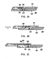
- Figs. 2A-2E are diagrams sequentially illustrating an operation process of the handheld electronic device 100 from a close state to a spread state.
- Fig. 2A is a schematic diagram illustrating the handheld electronic device in the close state.
- the first elastic member 150 is disposed between the first body 110 and the sliding block 130 for providing energy to move the first body 110 during a spread or a close process of the handheld electronic device 100.
- the handheld electronic device 100 has a semi-auto sliding function.
- the opposite sides of the first body 110 and the second body 120 respectively have a mutually-matched concave, so that when the handheld electronic device 100 is in a totally close state, the first body 110 and the second body 120 can be mutually stacked and may have an integral appearance.
- the sliding block 130, the linkage mechanism 140 and the first elastic member 150 are in an initial state.
- the first elastic member 150 can be a torsion spring, a coil spring or other elastic members that can achieve the semi-auto sliding.
- the first elastic member 150 is a pair of torsion spring.
- the first body 110 when a user pushes the first body 110, the first body 110 is slid relative to the second body 120 along the direction H, and the first elastic member 150 starts to store an elastic potential energy.
- the first elastic member 150 releases the stored elastic potential energy and automatically drives the first body 110 towards a force-applying direction of the user.
- the handheld electronic device 100 is totally spread, and the first body 110 enters the lower place of the concave of the second body 120.
- a first upper plane 111 of the first body 110 and a second upper plane 121 of the second body 120 are in a coplanar state.
- a side edge where the first body 110 leans against the second body 120 in the concave has a tilt angle.
- the tilt angle is, for example, between 55 degrees to 75 degrees.
- the tilt angle is, for example, 65 degrees.
- the linkage mechanism 140 drives the block 130, so that the first body 110 is rotated relative to the second body 120.
- the first body 110 is slid relative to the sliding block 130.
- the first elastic member 150 stores an elastic potential energy.
- the user pushes the first body 110 to the threshold position, the first elastic member 150 releases the stored elastic potential energy to accomplish the remained operation process, so that the first body 110 and the second body 120 are recovered to a stacked state shown as Fig. 2A . Therefore, the handheld electronic device 100 can provide the semi-auto sliding function.
- torsion spring is applied to serve as the first elastic member 150
- other types of the spring such as a coil spring or other types of the elastic member can also be applied to achieve the semi-auto sliding function.
- a positioning mechanism such as a magnet, a latch mechanism or a hook, etc. (which are described later) can also be applied to limit relative positions of the first body 110 and the second body 120 under the spread state.
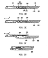
- Figs. 3A-3D are diagrams illustrating an operation process of a handheld electronic device from a close state to a spread state according to another embodiment of the present invention
- Figs. 3E-3G are diagrams illustrating an operation process of the handheld electronic device from the spread state to the close state.
- a second elastic member 270 is further configured between a second body 220 and a linkage mechanism 240 to provide energy required for rotating the linkage mechanism 142 during the spread and the close process of the handheld electronic device 200.
- a positioning mechanism 260 is further disposed between a first body 210 and the second body 220 to limit the relative positions of the first body 210 and the second body 220 after the first body 210 and the second body 220 are spread.
- the linkage mechanism 240 cannot be self-rotated to elevate the first body 210.
- the handheld electronic device 200 is changed to a bar-type handheld electronic device, and the user can directly perform the phone call, input data or watch multimedia information, etc. through the spread state handheld electronic device.
- the positioning mechanism 260 for example includes a first magnetic member 262 and a second magnetic member 264.
- the first magnetic member 262 is disposed on the first body 210
- the second magnetic member 264 is disposed on the second body 220.
- the first magnetic member 262 and the second magnetic member 264 are mutually magnetic attracted after the first body 210 and the second body 220 are spread, so as to limit the relative positions of the first body 210 and the second body 220.
- the positioning mechanism 260 can also be substituted by mechanisms such as the latch mechanism, the hook, etc., so as to limit the relative positions of the first body 210 and the second body 220 under the spread state.
- a detailed operation flow of the handheld electronic device 200 is as follows.
- Fig. 3A is a schematic diagram illustrating the handheld electronic device 200 in the close state.
- a first elastic member 250 is configured between the first body 210 and a sliding block 230 for providing energy to move the first body 210 during the close process of the handheld electronic device 200.
- the first elastic member 250 is a coil spring.
- the opposite sides of the first body 210 and the second body 220 respectively have a mutually-matched concave, so that when the handheld electronic device 200 is in a totally close state, the first body 210 and the second body 220 can be mutually stacked and may have an integral appearance.
- the sliding block 230, the linkage mechanism 240 and the first elastic member 250 are in the initial state.
- the first body 210 when the user pushes the first body 210, the first body 210 is slid relative to the second body 220 along the direction H, and the first elastic member 250 is drove by the first body 210 and is extended to store an elastic potential energy.
- the linkage mechanism 240 drives the block 230, so that the first body 210 is moved into a lower place of the concave on the second body 220.
- the handheld electronic device 200 may include the positioning mechanism 260 to fix the relative positions of the first body 210 and the second body 220.
- the linkage mechanism 240 cannot be self-rotated to elevate the first body 210. For example, when the user uses the first body 210 and the second body 220 in the spread state to perform the phone call, and if the first body 210 is touched to the user's ear, a relative movement between the first body 210 and the second body 220 is prevented.
- the positioning mechanism 260 includes the first magnetic member 262 and the second magnetic member 264 respectively disposed in the first body 210 and the second body 220.
- the first magnetic member 262 and the second magnetic member 264 are mutually magnetic attracted to fix the relative positions of the first body 210 and the second body 220.
- the positioning mechanism 260 can also be substituted by mechanisms such as the latch mechanism, the hook, etc., so as to limit the relative positions of the first body 210 and the second body 220 under the spread state of the handheld electronic device.
- the second elastic member 270 is configured between the linkage mechanism 240 and the second body 220. After the first body enters the lower place of the concave of the second body 220, the second elastic member 270 is compressed to store an elastic potential energy.
- Figs. 3E-3G are diagrams illustrating an operation process of the handheld electronic device 200 from the spread state to the close state.
- the user spreads the first body 210 and the second body 220 along the direction H to stagger the relative positions of the first magnetic member 262 and the second magnetic member 264, so as to release a position-limiting effect of the first magnetic member 262 and the second magnetic member 264 to the first body 210 and the second body 220.
- the positioning mechanism 260 is the latch mechanism, or the hook, etc., the position-limiting effect of the latch mechanism or the hook can also be released when the user spreads the first body 210 and the second body 220 along the direction H.
- the side edge where the first body 210 leans against the second body 120 in the concave doesn't have any limitations due to the first body 210 can be put out.
- the tilt angle as described in the previous embodiment is not limited between 55 degrees to 75 degrees, and the side edge of the first body 210 can be any shape since the first body 210 can be put out.
- the second elastic member 270 releases the stored elastic potential energy to rotate the linkage mechanism 240, so that the bottom surface of the first body 210 is higher than the second body 220.
- the stored elastic potential energy released by the first elastic member 250 drives the first body 210 to move along the direction H, so as to achieve the close state of the handheld electronic device 200 shown in Fig. 3G .
- the handheld electronic device 100 may include a lock mechanism 144 disposed on the linkage mechanism 140.
- the lock mechanism 144 can drive a rotation of the linkage mechanism 140 to elevate the sliding block 130, so that a position of the sliding block 130 can be higher than that of the lock mechanism 144. Then, the first body 110 is moved along the direction H and passes over the lock mechanism to achieve the close state.
- Fig. 5A and Fig. 5B are schematic diagrams illustrating operations of the lock mechanism 144.
- the user pushes the first body 110 to move along the direction H.
- the position of the sliding block 130 is higher that of the lock mechanism 144.
- the first body 110 can be moved by the elastic potential energy stored in the first elastic member 150, so as to achieve the close state of the first body 110 and the second body 120.
- a rotatable member 126 is further configured between the first body 110 and the second body 120.
- the first body 110 is omitted in Fig. 6 .
- Fig. 7A and Fig. 7B are diagrams illustrating operations of the rotatable member.
- Fig. 7A after the handheld electronic device 100 is spread, a short edge of the first body 110 is leaned against the rotatable member 126, and the rotatable member 126 is pivotally disposed on the second body 120 along a rotation shaft 126a.
- Fig. 7B during the close process of the handheld electronic device 100, the rotatable member 126 rotates along the rotation shaft 126a, so that the first body 110 can smoothly overpass the concave of the second body 120, so as to avoid the interference between the first body 110 and the second body 120 that influences an operation feeling of the user.
- the rotatable member 126, the lock mechanism 144, the second elastic member 270 and the positioning mechanism 260 are not limited to the aforementioned embodiments, and combinations and variations of the devices can be made within reasonable range and design, so as to match actual requirements.
- the positioning mechanism 260 can be used for fixing the relative positions of the first body 110 and the second body 120, and application of the lock mechanism 144, the rotatable member 126 and the second elastic member 270 can smooth the close process of the first body 110.
- the relative movement direction of the first body 110 and the second body 120 is not limited to be along the direction of a long-axis A-A' of the handheld electronic device.
- the relative movement direction of the first body 110 and the second body 120 can be changed to be perpendicular to the direction of the long-axis A-A' of the handheld electronic device, so that the present invention can not only be applied to vertical sliding handheld electronic devices, but can also be applied to lateral sliding handheld electronic devices.
- the first body 110 has a first display interface 113, and the first display interface 113 can be a display or a touch screen.
- the second body 120 has an input interface 125, and the input interface 125 can be a keyboard, a touch keyboard or a touch screen.
- the first body 110 has the first display interface 113
- the second body 120 has a second display interface 123
- the first display interface 113 can be a display or a touch screen
- the second display interface 123 can be a touch screen.
- a control key 160 can be formed there between.
- the first body 110 and the second body 120 respectively comprise a part of the control key.
- a touch screen can be formed between the first body 110 and the second body 120. Therefore, patterns of the first body 110 and the second body 120 are not limited to the aforementioned descriptions, and combinations and variations thereof can be made within reasonable range, so as to match the actual requirements.
- the first body 110 or the second body 120 can respectively comprise the display interface and the input interface, or a touch panel can be applied to simultaneously provide a display function and an information input function.
- the sliding block and linkage mechanism are applied to meliorate a conventional sliding handheld electronic device having a concave in the spread state.
- the first and the second bodies are meliorated to be coplanar after being spread, and are partially stacked to contain the sliding block and the linkage mechanism, so as to improve a usage area of the sliding handheld electronic device.
- the present invention can further be applied to the vertical sliding handheld electronic devices and the lateral sliding handheld electronic device.
- the elastic member, the positioning mechanism, the lock mechanism and the rotatable member, etc. can be applied to improve a design flexibility, so as to match different design requirements.
- the first body may include the display interface
- the second body may include the keyboard.
- the first body and the second body man all include the touch screen, so that the first display interface 113 and the second display interface 123 may have an interactive function.
- application of the present invention is not limited to the vertical sliding handheld electronic devices, but is also adapted to the lateral sliding handheld electronic devices, so that the application and usage convenience of the present invention can be expended.
Abstract
Description
- The present application relates to a handheld electronic device. More particularly, the present application relates to a sliding handheld electronic device.
- With development of information technology, information is more easily obtained form electronic devices in daily life. On the other hand, as techniques for process engineering are improved, various handheld electronic devices have a development trend of lightness, slimness, shortness and smallness, and since the handheld electronic device are easy to be carried, it is generally accepted by people and utilized in people's daily life.
- Taking a mobile phone as an example, to easily carry the mobile phone around and to match different preferences and requirements, besides conventional bar-type phones, the mobile phones can be generally classified into flip phones, twist phones and slide phones, etc. Regarding the slide phone, an upper body and lower body thereof are stacked and are slidable relative to one another, so as to achieve different operation modes such as open and close, etc. Stacking of the two bodies avails miniaturizing a whole size of the slide phone, and the upper and lower bodies can be spread under a specific operation mode. However, limited to a mechanism design, when the current slide phone is spread, a part of stacked regions is still existed between the upper and lower bodies, so that an area usage rate of the upper and lower bodies is decreased, which is of no avail to a further miniaturization of the slide phone.
- On the other hand, when the upper and lower bodies of the slide phone are relatively slid, a certain height step is formed there between. The height step not only influences a whole appearance of the mobile phone, but also influences an operation convenience of a user. For example, to avoid an interference caused by the height step in use, a certain distance has to be kept between first row keys and the height step, so that maximization of a keyboard design cannot be achieved.
-
US 2007/0243896 discloses an extendible mobile electronic device with a housing having a first housing element comprising a first front surface and a first rear surface and a second housing element, comprising a second front surface and a second rear surface. Said first housing element, and said second housing element are extensibly supported to each other, such that said first and second housing elements can adopt a retracted position and an extended position with respect to each other. In said retracted position said first housing element and said second housing element are located substantially on top of each other, said first rear surface conformingly adjoining said second front surface. In said extended position said first housing element is displaced with respect to said second housing element and at least a section of said second front surface is adjoining said and flushing with said first front surface. -
EP 1 796 351 A1 discloses a mobile terminal having a first body, a second body slidably attached to the first body, and means for connecting the first body to the second body and allowing the second body to be moved between a closed position and an open position such that an overall thickness of the mobile terminal in the open position is thinner than an overall thickness of the mobile terminal in the closed position. The means includes a slide mechanism having at least one rail mechanism attached to the first body; and at least one slider mechanism attached to the second body and slidably engaged with the at least one rail mechanism. - The present application is directed to a handheld electronic device having two stacked bodies, in which upper surfaces of the two bodies can be spread to be coplanar.
- The present application provides a handheld electronic device including a first body, a second body, a sliding block and a linkage mechanism. The first body is stacked on the second body. The sliding block is located between the first body and the second body, and is slidably coupled to the first body. The linkage mechanism is connected between the sliding block and the second body to drive the sliding block moving relative to the second body, so that after the first body and the second body are spread along a direction, the first body and the second body are approximately coplanar.
- According to the above description, different from a conventional design that a height step is formed when the two bodies of the sliding handheld electronic device are spread, in the present application, by using the sliding block and the linkage mechanism, the two bodies are spread to be coplanar. Therefore, not only the sliding handheld electronic device may have a levelled appearance under a spread state, but also an operation convenience of a user can be improved.
- In order to make the aforementioned and other objects, features and advantages of the present invention comprehensible, a preferred embodiment accompanied with figures is described in detail below.
- The accompanying drawings are included to provide a further understanding of the invention, and are incorporated in and constitute a part of this specification. The drawings illustrate embodiments of the invention and, together with the description, serve to explain the principles of the invention.
-
Fig. 1 is an explosion diagram illustrating a handheld electronic device according to an embodiment of the present invention. -
Figs. 2A-2E are diagrams illustrating a spread process of a handheld electronic device according to the embodiment of the present invention. -
Figs. 3A-3G are diagrams illustrating a spread and a close process of a handheld electronic device according to another embodiment of the present invention. -
Fig. 4 is a schematic diagram illustrating a handheld electronic device applying a lock mechanism of the present application. -
Fig. 5A and Fig. 5B are schematic diagrams illustrating operations of a lock mechanism ofFig. 4 . -
Fig. 6 is a schematic diagram illustrating a handheld electronic device applying a rotatable member of the present application. -
Fig. 7A and Fig. 7B are schematic diagrams illustrating operations of a rotatable member ofFig. 6 . -
Fig. 8 is a schematic diagram illustrating a spread vertical sliding handheld electronic device and a spread lateral sliding handheld electronic device of the present application. -
Fig. 9 is a schematic diagram illustrating a dual-screen sliding handheld electronic device of the present application. - In the following embodiments, detailed parts therein can be combined, substituted or omitted to cope with actual requirements. Those with ordinary skill in the art should understand the spirit and technique features of the present invention with reference of the following embodiments, and reasonable variations and applications can be made to the structure of the present invention without departing from the scope or spirit of the invention. Moreover, for simplicity's sake, and to make the descriptions comprehensive, like reference numerals refer to the like elements and repeated descriptions can be omitted.
-
Fig. 1 is an explosion diagram illustrating a handheld electronic device according to an embodiment of the present invention. Referring toFig. 1 , the handheldelectronic device 100 includes afirst body 110, asecond body 120, asliding block 130, alinkage mechanism 140 and a firstelastic member 150. Thefirst body 110 is stacked on thesecond body 120. The slidingblock 130, thelinkage mechanism 140 and the firstelastic member 150 are disposed between thefirst body 110 and thesecond body 120, so that thefirst body 110 and thesecond body 120 can be relatively slid along a direction H to switch operation modes of spread state and close state. - In the present embodiment, the
first body 110 includes a firstmain body 112 and afirst plate 114. The firstmain body 112 is disposed on thefirst plate 114, and thefirst plate 114 is slidably coupled to the slidingblock 130, so that the firstmain body 112 can be moved along the direction H relative to thesecond body 120 through thesliding block 130. Certainly, in the other embodiments of the present invention, thefirst plate 114 can also be omitted, so that thesliding block 130 is directly combined to the firstmain body 112. Thesecond body 120 includes a secondmain body 122 and asecond plate 124. Thelinkage mechanism 140 is connected between thesliding block 130 and the secondmain body 122. When thefirst body 110 and thesecond body 120 are spread along the direction H, thefirst body 110 is further moved relative to thesecond body 120 through thelinkage mechanism 140, so that thefirst body 110 and thesecond body 120 can be coplanar (shown asFig. 2E andFig. 3D in the followings), and thefirst body 110 and thesecond body 120 are partially stacked. - In detail, the
linkage mechanism 140 of the present embodiment is a parallel four-bar mechanism including four mutuallyparallel rods 142. Two ends of each of therod 142 are pivotally connected to the slidingblock 130 and the secondmain body 122, respectively. When thefirst body 110 and thesecond body 120 are spread along the direction H, thefirst body 110 is slid relative to the slidingblock 130, and when thefirst body 110 and the slidingblock 130 reach a limited position, thelinkage mechanism 142 is rotated while taking a pivot between therod 142 and the secondmain body 122 as a shaft, and accordingly drives the slidingblock 130 moving relative to the secondmain body 122, so that thefirst body 110 and thesecond body 120 are coplanar after being spread. -
Figs. 2A-2E are diagrams sequentially illustrating an operation process of the handheldelectronic device 100 from a close state to a spread state. - First,
Fig. 2A is a schematic diagram illustrating the handheld electronic device in the close state. The firstelastic member 150 is disposed between thefirst body 110 and the slidingblock 130 for providing energy to move thefirst body 110 during a spread or a close process of the handheldelectronic device 100. In other words, the handheldelectronic device 100 has a semi-auto sliding function. The opposite sides of thefirst body 110 and thesecond body 120 respectively have a mutually-matched concave, so that when the handheldelectronic device 100 is in a totally close state, thefirst body 110 and thesecond body 120 can be mutually stacked and may have an integral appearance. Now, the slidingblock 130, thelinkage mechanism 140 and the firstelastic member 150 are in an initial state. In the present embodiment, the firstelastic member 150 can be a torsion spring, a coil spring or other elastic members that can achieve the semi-auto sliding. In the present embodiment, the firstelastic member 150 is a pair of torsion spring. - Next, as shown in
Fig. 2B , when a user pushes thefirst body 110, thefirst body 110 is slid relative to thesecond body 120 along the direction H, and the firstelastic member 150 starts to store an elastic potential energy. - Next, as shown in
Fig. 2C , when thefirst body 110 is moved and reaches a threshold position, the firstelastic member 150 releases the stored elastic potential energy and automatically drives thefirst body 110 towards a force-applying direction of the user. - Meanwhile, as shown in
Fig. 2D , when thefirst body 110 is slid to a limited position elative to the slidingblock 130, thelinkage mechanism 140 is rotated and drives the slidingblock 130, so that thefirst body 110 is moved into a lower place of the concave on thesecond body 120. - Finally, as shown in
Fig. 2E , the handheldelectronic device 100 is totally spread, and thefirst body 110 enters the lower place of the concave of thesecond body 120. Now, a firstupper plane 111 of thefirst body 110 and a secondupper plane 121 of thesecond body 120 are in a coplanar state. - On the other hand, when the user wants to close the handheld
electronic device 100, the steps shown inFigs. 2A-2E are reversely performed to switch the handheldelectronic device 100 from the spread state ofFig. 2E to the close state ofFig. 2A . It should be noted that to smooth and facilitate the user pushing thefirst body 110 relative to thesecond body 120 along the direction H, a side edge where thefirst body 110 leans against thesecond body 120 in the concave has a tilt angle. Considering an easy slide during the close operation, the appearance and the operation convenience of the handheldelectronic device 100, the tilt angle is, for example, between 55 degrees to 75 degrees. Preferably, the tilt angle is, for example, 65 degrees. When thefirst body 110 is pushed, thelinkage mechanism 140 drives theblock 130, so that thefirst body 110 is rotated relative to thesecond body 120. When a bottom surface of thefirst body 110 is higher than the concave of thesecond body 120, thefirst body 110 is slid relative to the slidingblock 130. Now, the firstelastic member 150 stores an elastic potential energy. When the user pushes thefirst body 110 to the threshold position, the firstelastic member 150 releases the stored elastic potential energy to accomplish the remained operation process, so that thefirst body 110 and thesecond body 120 are recovered to a stacked state shown asFig. 2A . Therefore, the handheldelectronic device 100 can provide the semi-auto sliding function. - Though a pair of torsion spring is applied to serve as the first
elastic member 150, actually, in the other embodiments of the present invention, other types of the spring such as a coil spring or other types of the elastic member can also be applied to achieve the semi-auto sliding function. Moreover, in the present embodiment, a positioning mechanism such as a magnet, a latch mechanism or a hook, etc. (which are described later) can also be applied to limit relative positions of thefirst body 110 and thesecond body 120 under the spread state. By such means, the handheldelectronic device 100 is changed to a bar-type handheld electronic device, so that the user can directly perform a phone call, input data or watch multimedia information, etc. through the spread state handheld electronic device. -
Figs. 3A-3D are diagrams illustrating an operation process of a handheld electronic device from a close state to a spread state according to another embodiment of the present invention, andFigs. 3E-3G are diagrams illustrating an operation process of the handheld electronic device from the spread state to the close state. Compared to the aforementioned embodiment, a secondelastic member 270 is further configured between asecond body 220 and alinkage mechanism 240 to provide energy required for rotating thelinkage mechanism 142 during the spread and the close process of the handheldelectronic device 200. Moreover, in the present embodiment, apositioning mechanism 260 is further disposed between afirst body 210 and thesecond body 220 to limit the relative positions of thefirst body 210 and thesecond body 220 after thefirst body 210 and thesecond body 220 are spread. In other words, due to thepositioning mechanism 260, thelinkage mechanism 240 cannot be self-rotated to elevate thefirst body 210. For example, when the user uses thefirst body 210 and thesecond body 220 in the spread state to perform the phone call, and if thefirst body 210 is touched to the user's ear, a relative movement between thefirst body 210 and thesecond body 220 is prevented. By such means, the handheldelectronic device 200 is changed to a bar-type handheld electronic device, and the user can directly perform the phone call, input data or watch multimedia information, etc. through the spread state handheld electronic device. - In detail, the
positioning mechanism 260 for example includes a firstmagnetic member 262 and a secondmagnetic member 264. The firstmagnetic member 262 is disposed on thefirst body 210, and the secondmagnetic member 264 is disposed on thesecond body 220. The firstmagnetic member 262 and the secondmagnetic member 264 are mutually magnetic attracted after thefirst body 210 and thesecond body 220 are spread, so as to limit the relative positions of thefirst body 210 and thesecond body 220. However, thepositioning mechanism 260 can also be substituted by mechanisms such as the latch mechanism, the hook, etc., so as to limit the relative positions of thefirst body 210 and thesecond body 220 under the spread state. A detailed operation flow of the handheldelectronic device 200 is as follows. - First,
Fig. 3A is a schematic diagram illustrating the handheldelectronic device 200 in the close state. A firstelastic member 250 is configured between thefirst body 210 and a slidingblock 230 for providing energy to move thefirst body 210 during the close process of the handheldelectronic device 200. In the present embodiment, the firstelastic member 250 is a coil spring. The opposite sides of thefirst body 210 and thesecond body 220 respectively have a mutually-matched concave, so that when the handheldelectronic device 200 is in a totally close state, thefirst body 210 and thesecond body 220 can be mutually stacked and may have an integral appearance. Now, the slidingblock 230, thelinkage mechanism 240 and the firstelastic member 250 are in the initial state. - Next, as shown in
Fig. 3B , when the user pushes thefirst body 210, thefirst body 210 is slid relative to thesecond body 220 along the direction H, and the firstelastic member 250 is drove by thefirst body 210 and is extended to store an elastic potential energy. - Next, as shown in
Fig. 3C , when thefirst body 210 is slid to a limited position relative to the slidingblock 230, thelinkage mechanism 240 drives theblock 230, so that thefirst body 210 is moved into a lower place of the concave on thesecond body 220. - Finally, as shown in
Fig. 3D , thefirst body 210 enters the lower place of the concave of thesecond body 220, and now a firstupper plane 211 and a secondupper plane 221 are in the coplanar state. The handheldelectronic device 200 may include thepositioning mechanism 260 to fix the relative positions of thefirst body 210 and thesecond body 220. As described above, due to thepositioning mechanism 260, thelinkage mechanism 240 cannot be self-rotated to elevate thefirst body 210. For example, when the user uses thefirst body 210 and thesecond body 220 in the spread state to perform the phone call, and if thefirst body 210 is touched to the user's ear, a relative movement between thefirst body 210 and thesecond body 220 is prevented. - In the present embodiment, the
positioning mechanism 260 includes the firstmagnetic member 262 and the secondmagnetic member 264 respectively disposed in thefirst body 210 and thesecond body 220. The firstmagnetic member 262 and the secondmagnetic member 264 are mutually magnetic attracted to fix the relative positions of thefirst body 210 and thesecond body 220. However, thepositioning mechanism 260 can also be substituted by mechanisms such as the latch mechanism, the hook, etc., so as to limit the relative positions of thefirst body 210 and thesecond body 220 under the spread state of the handheld electronic device. Meanwhile, the secondelastic member 270 is configured between thelinkage mechanism 240 and thesecond body 220. After the first body enters the lower place of the concave of thesecond body 220, the secondelastic member 270 is compressed to store an elastic potential energy. -
Figs. 3E-3G are diagrams illustrating an operation process of the handheldelectronic device 200 from the spread state to the close state. - As shown in
Fig. 3E , during the close process of the handheldelectronic device 200 of the present embodiment, the user spreads thefirst body 210 and thesecond body 220 along the direction H to stagger the relative positions of the firstmagnetic member 262 and the secondmagnetic member 264, so as to release a position-limiting effect of the firstmagnetic member 262 and the secondmagnetic member 264 to thefirst body 210 and thesecond body 220. If thepositioning mechanism 260 is the latch mechanism, or the hook, etc., the position-limiting effect of the latch mechanism or the hook can also be released when the user spreads thefirst body 210 and thesecond body 220 along the direction H. Meanwhile, it should be noted that the side edge where thefirst body 210 leans against thesecond body 120 in the concave doesn't have any limitations due to thefirst body 210 can be put out. In other words, the tilt angle as described in the previous embodiment is not limited between 55 degrees to 75 degrees, and the side edge of thefirst body 210 can be any shape since thefirst body 210 can be put out. - As shown in
Fig. 3F , when the user releases thefirst body 210, the secondelastic member 270 releases the stored elastic potential energy to rotate thelinkage mechanism 240, so that the bottom surface of thefirst body 210 is higher than thesecond body 220. Now, the stored elastic potential energy released by the firstelastic member 250 drives thefirst body 210 to move along the direction H, so as to achieve the close state of the handheldelectronic device 200 shown inFig. 3G . - Moreover, as shown in
Fig. 4 , during the close process, when thefirst body 110 contacts thesecond body 120, it may not be easy to elevate thefirst body 110 to be higher than thesecond body 120 to achieve the close state. Therefore, to smoothly achieve the close state of thefirst body 110 and thesecond body 120, the handheldelectronic device 100 may include alock mechanism 144 disposed on thelinkage mechanism 140. During the close process, when thefirst body 110 touches thelock mechanism 144, thelock mechanism 144 can drive a rotation of thelinkage mechanism 140 to elevate the slidingblock 130, so that a position of the slidingblock 130 can be higher than that of thelock mechanism 144. Then, thefirst body 110 is moved along the direction H and passes over the lock mechanism to achieve the close state. -
Fig. 5A and Fig. 5B are schematic diagrams illustrating operations of thelock mechanism 144. When the handheldelectronic device 100 is about to be closed, the user pushes thefirst body 110 to move along the direction H. Next, as shown inFig. 5B , when thefirs body 110 pushes thelock mechanism 144 to rotate thelinkage mechanism 140, the position of the slidingblock 130 is higher that of thelock mechanism 144. Now, thefirst body 110 can be moved by the elastic potential energy stored in the firstelastic member 150, so as to achieve the close state of thefirst body 110 and thesecond body 120. - Moreover, as shown in
Fig. 6 , as described above, to resolve a problem of un-smooth sliding between thefirst body 110 and thesecond body 120 caused by interference between thefirst body 110 and thesecond body 120 during the close process, arotatable member 126 is further configured between thefirst body 110 and thesecond body 120. To clearly illustrate a design of the rotatable member, thefirst body 110 is omitted inFig. 6 . -
Fig. 7A and Fig. 7B are diagrams illustrating operations of the rotatable member. As shown inFig. 7A , after the handheldelectronic device 100 is spread, a short edge of thefirst body 110 is leaned against therotatable member 126, and therotatable member 126 is pivotally disposed on thesecond body 120 along a rotation shaft 126a. As shown inFig. 7B , during the close process of the handheldelectronic device 100, therotatable member 126 rotates along the rotation shaft 126a, so that thefirst body 110 can smoothly overpass the concave of thesecond body 120, so as to avoid the interference between thefirst body 110 and thesecond body 120 that influences an operation feeling of the user. - It should be noted that the
rotatable member 126, thelock mechanism 144, the secondelastic member 270 and thepositioning mechanism 260 are not limited to the aforementioned embodiments, and combinations and variations of the devices can be made within reasonable range and design, so as to match actual requirements. For example, thepositioning mechanism 260 can be used for fixing the relative positions of thefirst body 110 and thesecond body 120, and application of thelock mechanism 144, therotatable member 126 and the secondelastic member 270 can smooth the close process of thefirst body 110. - As shown in
Fig. 8 , the relative movement direction of thefirst body 110 and thesecond body 120 is not limited to be along the direction of a long-axis A-A' of the handheld electronic device. To match other applications, the relative movement direction of thefirst body 110 and thesecond body 120 can be changed to be perpendicular to the direction of the long-axis A-A' of the handheld electronic device, so that the present invention can not only be applied to vertical sliding handheld electronic devices, but can also be applied to lateral sliding handheld electronic devices. In detail, thefirst body 110 has afirst display interface 113, and thefirst display interface 113 can be a display or a touch screen. Thesecond body 120 has aninput interface 125, and theinput interface 125 can be a keyboard, a touch keyboard or a touch screen. - Moreover, as shown in
Fig. 9 , thefirst body 110 has thefirst display interface 113, and thesecond body 120 has asecond display interface 123, wherein thefirst display interface 113 can be a display or a touch screen, and thesecond display interface 123 can be a touch screen. In addition, when thefirst body 110 and thesecond body 120 are in the spread state, acontrol key 160 can be formed there between. In other words, thefirst body 110 and thesecond body 120 respectively comprise a part of the control key. Similarly, a touch screen can be formed between thefirst body 110 and thesecond body 120. Therefore, patterns of thefirst body 110 and thesecond body 120 are not limited to the aforementioned descriptions, and combinations and variations thereof can be made within reasonable range, so as to match the actual requirements. For example, thefirst body 110 or thesecond body 120 can respectively comprise the display interface and the input interface, or a touch panel can be applied to simultaneously provide a display function and an information input function. - In summary, in the present invention, the sliding block and linkage mechanism are applied to meliorate a conventional sliding handheld electronic device having a concave in the spread state. According to the present application, the first and the second bodies are meliorated to be coplanar after being spread, and are partially stacked to contain the sliding block and the linkage mechanism, so as to improve a usage area of the sliding handheld electronic device. Besides, the present invention can further be applied to the vertical sliding handheld electronic devices and the lateral sliding handheld electronic device. Moreover, in design of the sliding handheld electronic device, the elastic member, the positioning mechanism, the lock mechanism and the rotatable member, etc. can be applied to improve a design flexibility, so as to match different design requirements. For example, the first body may include the display interface, and the second body may include the keyboard. Alternatively, the first body and the second body man all include the touch screen, so that the
first display interface 113 and thesecond display interface 123 may have an interactive function. Moreover, application of the present invention is not limited to the vertical sliding handheld electronic devices, but is also adapted to the lateral sliding handheld electronic devices, so that the application and usage convenience of the present invention can be expended.
Claims (11)
- A handheld electronic device, comprising:a first body (110, 210);a second body (120, 220), wherein the first body (110, 210) is stacked on the second body (120, 220), and a side of the second body (120, 220) facing the first body (110, 210) has a step;a sliding block (130, 230), located between the first body (110, 210) and the second body (120, 220), and slidably coupled to the first body (110, 210); anda linkage mechanism (140, 240), connected between the sliding block (130, 230) andthe second body (120, 220) to drive the sliding block (130, 230) moving relative to the second body (120, 220), wherein the handheld electronic device is characterized in further comprising:a first elastic member (150, 250), disposed between the first body (110, 210) and the sliding block (130, 230),a second elastic member (270), disposed between the second body (120, 220) and the linkage mechanism (140, 240);a positioning mechanism (260), disposed between the first body (110, 210) and the second body (120, 220);wherein for receiving a spread state of the handheld electronic device, the first body (110, 210) and the second body (120,220) are adapted to spread along a direction, the first body (110, 210) is adapted to enter a lower place of the step, such that a top surface of the first body (110, 210) and a top surface of the second body (120, 220) are approximately coplanar, and the first and the second elastic members (150, 250, 270) are adapted to store an elastic energy,and for receiving a closed state of the handheld electronic device , the first body (110, 210) and the second body (120, 220) are adapted to spread along the same direction for a further distance, wherein the first elastic member (150, 250) releases the stored elastic energy for retracting the first body (110, 210) and the second body (120, 220) and the second elastic member (270) releases the stored elastic energy for rotating the linkage mechanism (140, 240).
- The handheld electronic device as claimed in claim 1, wherein the linkage mechanism (140,240) is a parallel four-bar mechanism comprising four parallel rod, and two ends of each rod are pivotally connected to the sliding block (130, 230) and the second body (120, 220), respectively.
- The handheld electronic device as claimed in claim 1, wherein the first elastic member (150, 250) comprises a torsion spring or a coil spring.
- The handheld electronic device as claimed in claim 1, wherein the positioning mechanism comprises a first magnetic member and a second magnetic member respectively disposed on the first body (110, 210) and the second body (120, 220), wherein the first magnetic member and the second magnetic member are mutually magnetic attracted after the first body (110, 210) and the second body (120, 220) are spread.
- The handheld electronic device as claimed in claim 1 further comprising a lock mechanism disposed on the linkage mechanism (140, 240), and the lock mechanism leaning against the sliding block (130, 230) after the first body (110, 210) and the second body (120, 220) are spread.
- The handheld electronic device as claimed in claim 1 further comprising a rotatable member disposed at a junction of the first body (110, 210) and the second body (120, 220), wherein the rotatable member is pivotally disposed on the second body (120, 220) and leans against the first body (110, 210), and is rotated along with a relative movement of the first body (110, 210) and the second body (120, 220).
- The handheld electronic device as claimed in claim 1, wherein the first body (110, 210) and the second body (120, 220) respectively have a long-axis direction, and the long-axis directions of the first body (110, 210) and the second body (120, 220) are respectively parallel to the direction.
- The handheld electronic device as claimed in claim 1, wherein the first body (110, 210) and the second body (120, 220) respectively have a long-axis direction, and the long-axis directions of the first body (110, 210) and the second body (120, 220) are respectively perpendicular to the direction.
- The handheld electronic device as claimed in claim 1, wherein a side of the first body (110, 210) departing from the sliding block (130, 230) has a first display interface.
- The handheld electronic device as claimed in claim 9, wherein a side of the second body (120, 220) facing the sliding block (130, 230) has an input interface, and the input interface is exposed when the first body (110, 210) and the second body (120, 220) are spread.
- The handheld electronic device as claimed in claim 9, wherein a side of the second body (120, 220) facing the sliding block (130,230) has a second display interface, and the second display interface is exposed when the first body (110, 210) and the second body (120, 220) are spread.
Applications Claiming Priority (1)
| Application Number | Priority Date | Filing Date | Title |
|---|---|---|---|
| TW097147399A TWI372552B (en) | 2008-12-05 | 2008-12-05 | Handheld electronic device |
Publications (2)
| Publication Number | Publication Date |
|---|---|
| EP2194693A1 EP2194693A1 (en) | 2010-06-09 |
| EP2194693B1 true EP2194693B1 (en) | 2011-11-16 |
Family
ID=40756298
Family Applications (1)
| Application Number | Title | Priority Date | Filing Date |
|---|---|---|---|
| EP09004834A Active EP2194693B1 (en) | 2008-12-05 | 2009-04-01 | Handheld electronic device |
Country Status (4)
| Country | Link |
|---|---|
| US (1) | US8140135B2 (en) |
| EP (1) | EP2194693B1 (en) |
| AT (1) | ATE534230T1 (en) |
| TW (1) | TWI372552B (en) |
Families Citing this family (17)
| Publication number | Priority date | Publication date | Assignee | Title |
|---|---|---|---|---|
| TWI362209B (en) * | 2008-10-08 | 2012-04-11 | Htc Corp | Portable electronic device |
| US9052874B2 (en) * | 2008-11-14 | 2015-06-09 | Nokia Technologies Oy | Handheld device with a user interface |
| CN101753647A (en) * | 2008-12-22 | 2010-06-23 | 鸿富锦精密工业(深圳)有限公司 | Divide-body mobile phone |
| US8121661B2 (en) * | 2009-03-03 | 2012-02-21 | Sony Ericsson Mobile Communications Ab | Mechanism for radio communication terminal |
| US8948824B2 (en) | 2009-08-05 | 2015-02-03 | Apple Inc. | Electronic devices with clips |
| CN102123568A (en) * | 2010-01-07 | 2011-07-13 | 深圳富泰宏精密工业有限公司 | Sliding mechanism and portable electronic device applying same |
| US8374658B2 (en) * | 2010-04-26 | 2013-02-12 | Nokia Corporation | Method and apparatus for flat and tilt slide mechanism |
| TWI376928B (en) * | 2010-07-29 | 2012-11-11 | Htc Corp | Handheld electronic device |
| TWI426766B (en) * | 2010-07-30 | 2014-02-11 | Htc Corp | Handheld electronic device |
| KR101792502B1 (en) * | 2010-08-12 | 2017-11-02 | 엘지전자 주식회사 | Mobile terminal |
| TWI423186B (en) * | 2010-12-31 | 2014-01-11 | Giga Byte Tech Co Ltd | Replaceable apparatus |
| US8611973B2 (en) * | 2011-03-07 | 2013-12-17 | Blackberry Limited | Slidable portable electronic device with keypad portion adapted for covering display |
| CN102892262B (en) * | 2011-07-21 | 2015-03-11 | 鸿富锦精密工业(深圳)有限公司 | Portable electronic device |
| TWI488571B (en) | 2011-08-19 | 2015-06-11 | Au Optronics Corp | Portable electronic device |
| TWI511643B (en) * | 2012-08-07 | 2015-12-01 | Wistron Corp | Portable computer |
| JP2015180113A (en) * | 2015-06-30 | 2015-10-08 | 三菱製鋼株式会社 | Opening/closing device |
| TWI612412B (en) * | 2017-02-22 | 2018-01-21 | 啓碁科技股份有限公司 | Handfree electric device |
Family Cites Families (4)
| Publication number | Priority date | Publication date | Assignee | Title |
|---|---|---|---|---|
| KR100631897B1 (en) * | 2005-01-19 | 2006-10-11 | 삼성전기주식회사 | Tilt open / close mobile communication terminal |
| ATE532317T1 (en) * | 2005-04-06 | 2011-11-15 | Nokia Corp | EXPANDABLE MOBILE ELECTRONIC DEVICE |
| EP1796351B1 (en) | 2005-12-12 | 2016-10-19 | LG Electronics Inc. | Sliding type mobile communication terminal |
| US7627337B2 (en) | 2006-04-17 | 2009-12-01 | Nokia Corporation | Dual lever slide mechanism for extendible device housings |
-
2008
- 2008-12-05 TW TW097147399A patent/TWI372552B/en active
-
2009
- 2009-03-18 US US12/406,126 patent/US8140135B2/en active Active
- 2009-04-01 EP EP09004834A patent/EP2194693B1/en active Active
- 2009-04-01 AT AT09004834T patent/ATE534230T1/en active
Also Published As
| Publication number | Publication date |
|---|---|
| US8140135B2 (en) | 2012-03-20 |
| ATE534230T1 (en) | 2011-12-15 |
| EP2194693A1 (en) | 2010-06-09 |
| TW201023594A (en) | 2010-06-16 |
| US20100144408A1 (en) | 2010-06-10 |
| TWI372552B (en) | 2012-09-11 |
Similar Documents
| Publication | Publication Date | Title |
|---|---|---|
| EP2194693B1 (en) | Handheld electronic device | |
| EP3206379B1 (en) | Handheld electronic device | |
| EP1867143B1 (en) | Extensible mobile electronic device | |
| US7197346B2 (en) | Mobile electronic device having pivotable display element | |
| US8200300B2 (en) | Sliding electronic device | |
| US8180417B2 (en) | Portable terminal | |
| US20140049888A1 (en) | Portable communication device and cradle apparatus thereof | |
| KR101048031B1 (en) | Mobile device | |
| EP2285074B1 (en) | Handheld electronic device and rising mechanism | |
| JP2011515929A (en) | Mobile communication device having slider and flip hinge assembly | |
| US8797730B2 (en) | Sliding module for electronic device | |
| KR20090129647A (en) | Sliding device and slide type portable information device having the same | |
| JP5733311B2 (en) | Slide mechanism and portable device | |
| KR101000000B1 (en) | Hinge apparatus and portable terminal using the same | |
| JP4667622B2 (en) | Transfer mechanism and display device | |
| KR101144133B1 (en) | Portable device with split keypad | |
| KR101264732B1 (en) | Personal portable device capable of multiple opening and closing | |
| KR101310211B1 (en) | Personal portable device capable of tilting | |
| KR101351488B1 (en) | Mobile Communication Terminal | |
| KR101007846B1 (en) | hinge module and mobile communication terminal using hinge module | |
| KR20120047504A (en) | Hinge apparatus for mobile phone | |
| KR100874765B1 (en) | Coupling apparatus of mobile phone in capable of rotating and sliding | |
| KR20120136616A (en) | Personal portable device capable of multiple opening and closing | |
| KR20070002727A (en) | 2-way semiautomatic sliding module and personal portable device having the sliding module | |
| KR20120026268A (en) | Slide-tilt hinge device for mobile phone |
Legal Events
| Date | Code | Title | Description |
|---|---|---|---|
| PUAI | Public reference made under article 153(3) epc to a published international application that has entered the european phase |
Free format text: ORIGINAL CODE: 0009012 |
|
| 17P | Request for examination filed |
Effective date: 20090402 |
|
| AK | Designated contracting states |
Kind code of ref document: A1 Designated state(s): AT BE BG CH CY CZ DE DK EE ES FI FR GB GR HR HU IE IS IT LI LT LU LV MC MK MT NL NO PL PT RO SE SI SK TR |
|
| AX | Request for extension of the european patent |
Extension state: AL BA RS |
|
| 17Q | First examination report despatched |
Effective date: 20100915 |
|
| RIC1 | Information provided on ipc code assigned before grant |
Ipc: H04M 1/02 20060101AFI20110606BHEP |
|
| GRAP | Despatch of communication of intention to grant a patent |
Free format text: ORIGINAL CODE: EPIDOSNIGR1 |
|
| GRAS | Grant fee paid |
Free format text: ORIGINAL CODE: EPIDOSNIGR3 |
|
| GRAA | (expected) grant |
Free format text: ORIGINAL CODE: 0009210 |
|
| AK | Designated contracting states |
Kind code of ref document: B1 Designated state(s): AT BE BG CH CY CZ DE DK EE ES FI FR GB GR HR HU IE IS IT LI LT LU LV MC MK MT NL NO PL PT RO SE SI SK TR |
|
| REG | Reference to a national code |
Ref country code: GB Ref legal event code: FG4D |
|
| REG | Reference to a national code |
Ref country code: CH Ref legal event code: EP |
|
| REG | Reference to a national code |
Ref country code: IE Ref legal event code: FG4D |
|
| REG | Reference to a national code |
Ref country code: DE Ref legal event code: R096 Ref document number: 602009003661 Country of ref document: DE Effective date: 20120112 |
|
| REG | Reference to a national code |
Ref country code: NL Ref legal event code: T3 |
|
| LTIE | Lt: invalidation of european patent or patent extension |
Effective date: 20111116 |
|
| PG25 | Lapsed in a contracting state [announced via postgrant information from national office to epo] |
Ref country code: LT Free format text: LAPSE BECAUSE OF FAILURE TO SUBMIT A TRANSLATION OF THE DESCRIPTION OR TO PAY THE FEE WITHIN THE PRESCRIBED TIME-LIMIT Effective date: 20111116 Ref country code: NO Free format text: LAPSE BECAUSE OF FAILURE TO SUBMIT A TRANSLATION OF THE DESCRIPTION OR TO PAY THE FEE WITHIN THE PRESCRIBED TIME-LIMIT Effective date: 20120216 Ref country code: IS Free format text: LAPSE BECAUSE OF FAILURE TO SUBMIT A TRANSLATION OF THE DESCRIPTION OR TO PAY THE FEE WITHIN THE PRESCRIBED TIME-LIMIT Effective date: 20120316 |
|
| PG25 | Lapsed in a contracting state [announced via postgrant information from national office to epo] |
Ref country code: LV Free format text: LAPSE BECAUSE OF FAILURE TO SUBMIT A TRANSLATION OF THE DESCRIPTION OR TO PAY THE FEE WITHIN THE PRESCRIBED TIME-LIMIT Effective date: 20111116 Ref country code: SE Free format text: LAPSE BECAUSE OF FAILURE TO SUBMIT A TRANSLATION OF THE DESCRIPTION OR TO PAY THE FEE WITHIN THE PRESCRIBED TIME-LIMIT Effective date: 20111116 Ref country code: PL Free format text: LAPSE BECAUSE OF FAILURE TO SUBMIT A TRANSLATION OF THE DESCRIPTION OR TO PAY THE FEE WITHIN THE PRESCRIBED TIME-LIMIT Effective date: 20111116 Ref country code: BE Free format text: LAPSE BECAUSE OF FAILURE TO SUBMIT A TRANSLATION OF THE DESCRIPTION OR TO PAY THE FEE WITHIN THE PRESCRIBED TIME-LIMIT Effective date: 20111116 Ref country code: PT Free format text: LAPSE BECAUSE OF FAILURE TO SUBMIT A TRANSLATION OF THE DESCRIPTION OR TO PAY THE FEE WITHIN THE PRESCRIBED TIME-LIMIT Effective date: 20120316 Ref country code: GR Free format text: LAPSE BECAUSE OF FAILURE TO SUBMIT A TRANSLATION OF THE DESCRIPTION OR TO PAY THE FEE WITHIN THE PRESCRIBED TIME-LIMIT Effective date: 20120217 Ref country code: HR Free format text: LAPSE BECAUSE OF FAILURE TO SUBMIT A TRANSLATION OF THE DESCRIPTION OR TO PAY THE FEE WITHIN THE PRESCRIBED TIME-LIMIT Effective date: 20111116 Ref country code: SI Free format text: LAPSE BECAUSE OF FAILURE TO SUBMIT A TRANSLATION OF THE DESCRIPTION OR TO PAY THE FEE WITHIN THE PRESCRIBED TIME-LIMIT Effective date: 20111116 |
|
| PG25 | Lapsed in a contracting state [announced via postgrant information from national office to epo] |
Ref country code: CY Free format text: LAPSE BECAUSE OF FAILURE TO SUBMIT A TRANSLATION OF THE DESCRIPTION OR TO PAY THE FEE WITHIN THE PRESCRIBED TIME-LIMIT Effective date: 20111116 |
|
| PG25 | Lapsed in a contracting state [announced via postgrant information from national office to epo] |
Ref country code: BG Free format text: LAPSE BECAUSE OF FAILURE TO SUBMIT A TRANSLATION OF THE DESCRIPTION OR TO PAY THE FEE WITHIN THE PRESCRIBED TIME-LIMIT Effective date: 20120216 Ref country code: CZ Free format text: LAPSE BECAUSE OF FAILURE TO SUBMIT A TRANSLATION OF THE DESCRIPTION OR TO PAY THE FEE WITHIN THE PRESCRIBED TIME-LIMIT Effective date: 20111116 Ref country code: DK Free format text: LAPSE BECAUSE OF FAILURE TO SUBMIT A TRANSLATION OF THE DESCRIPTION OR TO PAY THE FEE WITHIN THE PRESCRIBED TIME-LIMIT Effective date: 20111116 Ref country code: SK Free format text: LAPSE BECAUSE OF FAILURE TO SUBMIT A TRANSLATION OF THE DESCRIPTION OR TO PAY THE FEE WITHIN THE PRESCRIBED TIME-LIMIT Effective date: 20111116 Ref country code: EE Free format text: LAPSE BECAUSE OF FAILURE TO SUBMIT A TRANSLATION OF THE DESCRIPTION OR TO PAY THE FEE WITHIN THE PRESCRIBED TIME-LIMIT Effective date: 20111116 |
|
| PG25 | Lapsed in a contracting state [announced via postgrant information from national office to epo] |
Ref country code: IT Free format text: LAPSE BECAUSE OF FAILURE TO SUBMIT A TRANSLATION OF THE DESCRIPTION OR TO PAY THE FEE WITHIN THE PRESCRIBED TIME-LIMIT Effective date: 20111116 Ref country code: RO Free format text: LAPSE BECAUSE OF FAILURE TO SUBMIT A TRANSLATION OF THE DESCRIPTION OR TO PAY THE FEE WITHIN THE PRESCRIBED TIME-LIMIT Effective date: 20111116 |
|
| REG | Reference to a national code |
Ref country code: AT Ref legal event code: MK05 Ref document number: 534230 Country of ref document: AT Kind code of ref document: T Effective date: 20111116 |
|
| PLBE | No opposition filed within time limit |
Free format text: ORIGINAL CODE: 0009261 |
|
| STAA | Information on the status of an ep patent application or granted ep patent |
Free format text: STATUS: NO OPPOSITION FILED WITHIN TIME LIMIT |
|
| 26N | No opposition filed |
Effective date: 20120817 |
|
| PG25 | Lapsed in a contracting state [announced via postgrant information from national office to epo] |
Ref country code: MC Free format text: LAPSE BECAUSE OF NON-PAYMENT OF DUE FEES Effective date: 20120430 |
|
| REG | Reference to a national code |
Ref country code: DE Ref legal event code: R097 Ref document number: 602009003661 Country of ref document: DE Effective date: 20120817 |
|
| REG | Reference to a national code |
Ref country code: IE Ref legal event code: MM4A |
|
| PG25 | Lapsed in a contracting state [announced via postgrant information from national office to epo] |
Ref country code: IE Free format text: LAPSE BECAUSE OF NON-PAYMENT OF DUE FEES Effective date: 20120401 Ref country code: AT Free format text: LAPSE BECAUSE OF FAILURE TO SUBMIT A TRANSLATION OF THE DESCRIPTION OR TO PAY THE FEE WITHIN THE PRESCRIBED TIME-LIMIT Effective date: 20111116 |
|
| PG25 | Lapsed in a contracting state [announced via postgrant information from national office to epo] |
Ref country code: MK Free format text: LAPSE BECAUSE OF FAILURE TO SUBMIT A TRANSLATION OF THE DESCRIPTION OR TO PAY THE FEE WITHIN THE PRESCRIBED TIME-LIMIT Effective date: 20111116 |
|
| PG25 | Lapsed in a contracting state [announced via postgrant information from national office to epo] |
Ref country code: ES Free format text: LAPSE BECAUSE OF FAILURE TO SUBMIT A TRANSLATION OF THE DESCRIPTION OR TO PAY THE FEE WITHIN THE PRESCRIBED TIME-LIMIT Effective date: 20120227 |
|
| PG25 | Lapsed in a contracting state [announced via postgrant information from national office to epo] |
Ref country code: FI Free format text: LAPSE BECAUSE OF FAILURE TO SUBMIT A TRANSLATION OF THE DESCRIPTION OR TO PAY THE FEE WITHIN THE PRESCRIBED TIME-LIMIT Effective date: 20111116 |
|
| PG25 | Lapsed in a contracting state [announced via postgrant information from national office to epo] |
Ref country code: MT Free format text: LAPSE BECAUSE OF FAILURE TO SUBMIT A TRANSLATION OF THE DESCRIPTION OR TO PAY THE FEE WITHIN THE PRESCRIBED TIME-LIMIT Effective date: 20111116 |
|
| REG | Reference to a national code |
Ref country code: CH Ref legal event code: PL |
|
| PG25 | Lapsed in a contracting state [announced via postgrant information from national office to epo] |
Ref country code: LI Free format text: LAPSE BECAUSE OF NON-PAYMENT OF DUE FEES Effective date: 20130430 Ref country code: CH Free format text: LAPSE BECAUSE OF NON-PAYMENT OF DUE FEES Effective date: 20130430 |
|
| PG25 | Lapsed in a contracting state [announced via postgrant information from national office to epo] |
Ref country code: TR Free format text: LAPSE BECAUSE OF FAILURE TO SUBMIT A TRANSLATION OF THE DESCRIPTION OR TO PAY THE FEE WITHIN THE PRESCRIBED TIME-LIMIT Effective date: 20111116 |
|
| PG25 | Lapsed in a contracting state [announced via postgrant information from national office to epo] |
Ref country code: LU Free format text: LAPSE BECAUSE OF NON-PAYMENT OF DUE FEES Effective date: 20120401 |
|
| PG25 | Lapsed in a contracting state [announced via postgrant information from national office to epo] |
Ref country code: HU Free format text: LAPSE BECAUSE OF FAILURE TO SUBMIT A TRANSLATION OF THE DESCRIPTION OR TO PAY THE FEE WITHIN THE PRESCRIBED TIME-LIMIT Effective date: 20090401 |
|
| REG | Reference to a national code |
Ref country code: FR Ref legal event code: PLFP Year of fee payment: 7 |
|
| REG | Reference to a national code |
Ref country code: FR Ref legal event code: PLFP Year of fee payment: 8 |
|
| REG | Reference to a national code |
Ref country code: FR Ref legal event code: PLFP Year of fee payment: 9 |
|
| REG | Reference to a national code |
Ref country code: FR Ref legal event code: PLFP Year of fee payment: 10 |
|
| PGFP | Annual fee paid to national office [announced via postgrant information from national office to epo] |
Ref country code: FR Payment date: 20230309 Year of fee payment: 15 |
|
| PGFP | Annual fee paid to national office [announced via postgrant information from national office to epo] |
Ref country code: GB Payment date: 20230302 Year of fee payment: 15 |
|
| PGFP | Annual fee paid to national office [announced via postgrant information from national office to epo] |
Ref country code: NL Payment date: 20230314 Year of fee payment: 15 |
|
| P01 | Opt-out of the competence of the unified patent court (upc) registered |
Effective date: 20230602 |
|
| PGFP | Annual fee paid to national office [announced via postgrant information from national office to epo] |
Ref country code: DE Payment date: 20230307 Year of fee payment: 15 |