EP2194608A1 - Steckverbindungsvorrichtung - Google Patents
Steckverbindungsvorrichtung Download PDFInfo
- Publication number
- EP2194608A1 EP2194608A1 EP09014669A EP09014669A EP2194608A1 EP 2194608 A1 EP2194608 A1 EP 2194608A1 EP 09014669 A EP09014669 A EP 09014669A EP 09014669 A EP09014669 A EP 09014669A EP 2194608 A1 EP2194608 A1 EP 2194608A1
- Authority
- EP
- European Patent Office
- Prior art keywords
- plug
- connection device
- plug element
- components
- plug connection
- Prior art date
- Legal status (The legal status is an assumption and is not a legal conclusion. Google has not performed a legal analysis and makes no representation as to the accuracy of the status listed.)
- Granted
Links
Images
Classifications
-
- H—ELECTRICITY
- H01—ELECTRIC ELEMENTS
- H01R—ELECTRICALLY-CONDUCTIVE CONNECTIONS; STRUCTURAL ASSOCIATIONS OF A PLURALITY OF MUTUALLY-INSULATED ELECTRICAL CONNECTING ELEMENTS; COUPLING DEVICES; CURRENT COLLECTORS
- H01R13/00—Details of coupling devices of the kinds covered by groups H01R12/70 or H01R24/00 - H01R33/00
- H01R13/02—Contact members
- H01R13/15—Pins, blades or sockets having separate spring member for producing or increasing contact pressure
- H01R13/17—Pins, blades or sockets having separate spring member for producing or increasing contact pressure with spring member on the pin
Definitions
- the invention relates to a plug connection device, in particular for an electronic assembly of a commercial vehicle, with at least one plug element and a mating connector element, via which in the assembled state, an electrical connection can be established.
- the invention relates to an assembly, in particular an electronic assembly of a commercial vehicle, with at least one such connector device.
- the invention relates to a method for mounting a plug connection device in an assembly, in particular an electronic assembly of a commercial vehicle, wherein the plug connection device comprises at least one plug element and a mating connector element, on the mated state, an electrical connection is made.
- Such electronic assemblies are for example part of mechatronic assemblies and are preferably on housings or other components of mechanical assemblies, such as a gearbox mounted.
- the complete electronic assembly is attached, for example, to an inner side of a housing cover or of an upper housing part by means of a screw connection.
- the housing cover is in turn attached to a lower housing part or other component of the mechanical assembly.
- the electronic assembly comprises one or more of the generic connector devices.
- a plug element of the plug connection device is usually fixed to the upper housing part and coupled to the electronic module.
- a corresponding mating connector element of the connector device for mating with the male member is usually attached to the lower housing part and coupled for example with sensors or valves of the mechanical assembly.
- the assembling or assembly of the corresponding housing parts of the electronic and mechanical assembly is carried out conventionally by aligning the upper and lower housing part, wherein the plug and the mating connector element of the connector device, for example, via dowel pins and insertion be led together.
- the juxtaposition of the connector elements for the preparation of the electrical connection is therefore due to this covering housing parts exclusively on the aforementioned dowel pins and insertion bevels and no visual contact with the connector, so to speak, "blind".
- both the upper housing part and the lower housing part usually manufacturing and / or construction-related Dimensional deviations or high tolerances in all three dimensions or spatial directions on, whereby the juxtaposition of the connector elements is difficult. Therefore, there is a danger that contacts of the connector elements will be damaged during assembly of the modules, if their contacts are not accurately guided into position. Furthermore, the upper housing part and the lower housing part are to be sealed during assembly via a seal, while the connector elements must be performed simultaneously to each other, whereby the assembly is further complicated. It is particularly important to ensure that the connector elements are fastened as close as possible to each other, for example because of high vibration stresses of the mechanical assembly, to prevent contact friction between each plug element contacts as far as possible.
- the screw in the case of screwing the connector elements, it is also necessary to seal the screwed done from the outside.
- the disassembly effort of the connector device is also greatly increased.
- the screw in a service case, the screw must be solved, which includes relatively many small screws. Otherwise, the connector would be damaged during disassembly. When reassembling following disassembly, the screwing must be done again, with each screw to be resealed.
- Another possibility is to maintain the plug connection device via forces of plug contact springs of the respective plug elements, for example by a corresponding clamping.
- this results in the disadvantage that micro-movements can occur in contact zones of the plug contact springs of the respective plug elements, which can damage the plug contact springs in the contact zone.
- the electrical connection can be interrupted.
- the plug elements have not been "blinded" to one another in certain cases, but the coupling elements have to be coupled together before the housing parts or other components are assembled.
- the one plug element is pre-assembled to the upper housing part.
- the other connector element or the mating connector element is coupled directly under visual contact with the preassembled connector element.
- the mating connector element in this case is a loose mating connector element coupled to a cable or to flex lines. Only after the male member and the mating male member are coupled together to allow an electrical connection, the corresponding housing parts are coupled together.
- the cables or flex cables used for the loose mating connector element can be uncontrollably arranged inside the assembly by the assembly of the housing parts and thereby possibly be jammed. This can cause damage to the cables or flex cables used, causing a break in the electrical connection in the worst case.
- the invention is therefore the object of developing the generic connector devices and methods for mounting such connector devices such that the assembly cost can be reduced.
- the plug connection device builds on the generic state of the art in that at least one of the plug elements comprises at least two plug element components movable relative to one another within a play.
- the two plug element components can already be biased against one another with a certain spring force in the uninstalled state, wherein the two plug element components are then moved further relative to one another in the installed state, for example in the electronic module.
- this is done by abutment with a housing part, whereby the bias voltage between the connector element components increases at least temporarily.
- the corresponding housing part is screwed in the further assembly with a further housing part
- the corresponding plug member component is supported on the housing and urges on the spring element, the other connector element component in the direction of the plug element for producing the electrical connection.
- oscillations occurring in the assembly vibrations acting at least in the plug-in direction or z-direction, can be compensated.
- the force which acts through the spring element on the plug element component of the mating connector element electrically coupled to the corresponding plug element can thus be known to the game on the basis of a suitable design of the spring element, the spring constant, etc., prior to assembly be set. As soon as the plug rests against the corresponding housing part and the housing parts are installed together, the preset spring force comes into effect.
- the spring element is fixed with a correspondingly formed holding element in the desired position in the connector device;
- the plug element components of the corresponding plug element can completely absorb the spring element and fix it via corresponding holders.
- an extremely compact plug connection device can be provided, which also allows a space saving in the plug-in direction or in the z-direction by appropriate design of the plug element components of the corresponding plug element.
- the tolerances can be compensated during assembly of the connector device at least in the z-direction.
- a soft spring element with a large initial length is used, which can be compressed up to a certain length. Accordingly, causes an additional Pressweg, which is due to tolerances, only a very small spring force.
- the plug connection device according to the invention can be further developed in an advantageous manner such that the plug element components are movable in a plugging direction relative to each other within the game.
- the plug element components are movable in a plugging direction relative to each other within the game.
- the plug connection device according to the invention can be formed so that the other of the plug elements is made in one piece.
- the integrally produced male element to be mounted on a line carrier, while the compensation of tolerances and the compensation of vibrations occurring by the other plug element is made possible.
- both the plug element and the mating plug element comprise corresponding plug element components which are movable relative to each other within a game.
- the plug-in connection device can be realized such that one of the plug element components can be prestressed via a spring element against the other of the plug element components.
- the spring element is formed by a helical spring which is at least partially, preferably completely, accommodated in the plug element components of the corresponding plug element.
- the plug connection device according to the invention is preferably designed so that the plug connection device forms a flat plug connection or round plug connection.
- This flat plug connection or round plug connection is characterized by its robustness and is therefore particularly advantageous in connection with the assembly of the electronic and mechanical assembly.
- the plug element is electrically connected to the at least two plug element components with a flexible conductor carrier, for example with a flex circuit board, a punched grid, a ribbon cable, cables, etc.
- the assembly according to the invention which is in particular an electronic assembly of a commercial vehicle, comprises the plug connection device according to the invention.
- one of the plug elements is connected to electronics of the electronic module, for example a printed circuit board.
- the electronics can furthermore be connected to an upper housing part or an upper housing part.
- the other of the plug elements is electrically coupled to a conductor carrier or a flexible printed circuit board or a stamped grid, which is incorporated, for example, in a plastic holder.
- one of the plug elements can be coupled to a line carrier, which in turn is attached to a lower housing part or a lower housing part or to another component.
- the inventive method for mounting a plug connection device in an assembly, in particular an electronic assembly of a commercial vehicle is based on the generic state of the art in that during assembly of the plug element device, a first plug element component of one of the plug elements within a game relative to a second plug element component of a Plug element is moved.
- the method according to the invention can also be carried out with a plurality of plug connections, which respectively comprise plug elements and mating plug elements and are arranged at different positions within the module. Also in this case, only a corresponding joining or assembly process is carried out.
- the connector elements and mating connector elements of the connector devices according to the invention may be provided in each case on connector strips.
- the method according to the invention provides the features and advantages explained in connection with the plug-in connection device according to the invention in the same or similar manner, so reference is made to the corresponding statements in connection with the plug connection device according to the invention in order to avoid repetition.
- the inventive method can be developed in an advantageous manner such that the two connector element components are moved in a direction of insertion relative to each other within the game.
- the method according to the invention can be designed such that the other of the plug elements is mounted as a plug element produced in one piece.
- the method according to the invention can be implemented in such a way that one of the plug element components is biased against the other of the plug element components via a spring element.
- one of the plug element components comprises a contact surface for engagement with a housing component and is brought into abutment with the housing component and the other of the plug element components is coupled to the mating connector element.
- components of the plug connection device such as plug element and mating plug element, and in particular the plug element components, may be made of non-conductive material.
- a plastic has the advantage that it is inexpensive to manufacture and can be easily brought into the desired shape.
- conductive contact elements which are able to produce an electrical connection via plug element and mating connector element.
- These contact elements are expediently supported or supported by plug element and mating plug element, which thus serve as carrier elements for the contact elements. This makes it possible to firmly connect the contact elements with their support elements.
- the contact elements themselves do not have to be movably mounted and the electrical connection is made by each fixed elements. It can be provided that, for example, a spring used in the plug connection device also contributes to the electrical connection.
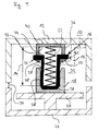
- FIG. 1 shows a schematic representation of a plug connection device 32 according to the invention according to an embodiment in cross section, which is suitable for carrying out the method according to the invention.
- the plug connection device 32 according to the invention is designed as a flat plug connection or round plug connection and in an electronic assembly 10 of a commercial vehicle intended.
- the assembly 10 may receive one or more of the connector devices 32 according to the invention, wherein for the sake of simplicity only a connector device 32 in FIG. 1 is shown.
- the plug connection device 32 has an integrally produced plug element 18 and a mating plug element 16, via which an electrical connection can be established in the assembled state.
- the mating connector element 16 in this case comprises two plug element components 36 and 38 which are movable relative to one another within a play, namely a first plug element component 36 and a second plug element component 38.
- the plug element components 36, 38 are relative to the plug connection device 32 in a plugging direction, ie z direction to each other within the game movable.
- the plug element components 36, 38 are equipped with a guide device 42.
- the guide device 42 is embodied such that the first plug element component 36 can be moved with a stop face 44 of the first plug element component 36 around the play up to a stop face 46 of the second plug element component 38 in the direction of the second plug element component 38.
- the guide device 42 is configured such that the first plug element component 36 can be moved away from the second plug element component 38 by a clearance until a stop 48 of the first plug element component 36 comes into contact with a further stop surface 50 of the second plug element component 38. In this case, the first and second connector element components 36, 38 have moved apart to a maximum extent.
- the plug element 18 comprises plug cavity contact elements, not shown in detail, in which plug pin contact elements of the mating plug element 16 can be plugged in a plugging direction (z direction) in order to produce the electrical connection.
- the first plug element component 36 comprises a contact surface 40 for engagement with an upper housing component 12, the contact surface 40 being provided on a side of the plug element component 36 facing away from the stop surface 44.
- the plug element 18 is immovably coupled via a corresponding attachment with a line carrier 20 or another part of the assembly 10.
- the plug element 18 is connected to on or in the line carrier 20 extending lines via corresponding plug contact elements; in particular, electrically conductive connections are provided between the conductor carrier 20 and the plug cavity contact elements.
- the conductor carrier 20 is further immovably coupled to a lower housing part or a lower housing part 26 or other component.
- the mating connector element 16 is preferably electrically coupled to a printed circuit board, not shown, wherein the printed circuit board in turn may be coupled to the upper housing part or the upper housing part 12 or any other component. Furthermore, each plug contact elements of the Mating connector element 16 is electrically coupled to lines of the printed circuit board, not shown.
- the plug contact elements of the mating connector element 16 may, for example, be attached to the second plug element component 38 in such a way that an electrical connection to the spring 22 exists. In particular, the electrical contact can be guided through the wall of the second connector element component 38.
- On the first plug element component 36 may be provided an electrical contact, which produces an electrically conductive contact with the spring 22 and lines of the printed circuit boards. This contact can be guided through the wall of the first connector component 36.
- first plug element component 36 and the second plug element component 38 are electrically connected directly to one another.
- conductor tracks may be provided which are guided on the walls of the connector element components 36, 38, and provide an electrical connection. Conveniently, such conductor tracks are configured to be in electrical contact even when they are moved against each other. How out FIG. 1 it can be seen, the male member 18 and the mating connector member 16 each insertion bevels 28 in the form of sliding surfaces or chamfers, whereby a mating of the connector elements 16, 18 is facilitated.
- the housing parts 12, 26 may be provided in the installed state, a seal, not shown, which prevents ingress of moisture into the housing interior.
- a seal not shown, which prevents ingress of moisture into the housing interior.
- the components of the connector device described here made of non-conductive material, in particular a plastic manufactured be. It is particularly expedient to form the plug member components 36, 38 and the plug member 18 made of plastic.
- the inventive method for mounting the connector device 32 according to the invention in the assembly 10 is designed as follows. First, for example, the printed circuit board, not shown, attached to the upper housing part 12 and brought into electrical connection with the mating connector element 16. Furthermore, the plug element 18 is attached to the cable carrier 20. The conductor carrier 20 is fixed to the lower housing part 26. Thus, the plug member 18 is pre-fixed to the lower housing part 26, while no fixed coupling between the mating connector element 16 and the upper housing part 12 is made. The mating connector element 16 is now at least partially inserted into the plug element 18 for producing the electrical connection, with the upper housing part 12 subsequently being guided on the lower housing part 26 or being installed with the lower housing part 26.
- the upper housing part 12 comes into contact with the contact surface 40 of the first connector element component 36 of the mating connector element 16, as shown in FIG FIG. 1 is shown.
- the upper housing part 12 is moved further in the direction of the lower housing part 26 and installed with this.
- the first plug element component 36 of the mating plug element 16 is moved against the bias of the spring element 22 in the direction of the plug element 18.
- the spring force of the spring element 22 is increased by the change in length 34, whereby the second male member member 38 is fully pushed into the male member 18 and is further pressed into the male member 18 due to the bias of the spring member 22.
Landscapes
- Details Of Connecting Devices For Male And Female Coupling (AREA)
Abstract
Description
- Die Erfindung betrifft eine Steckverbindungsvorrichtung, insbesondere für eine elektronische Baugruppe eines Nutzfahrzeugs, mit zumindest einem Steckerelement und einem Gegensteckerelement, über die im zusammengesteckten Zustand eine elektrische Verbindung herstellbar ist.
- Darüber hinaus betrifft die Erfindung eine Baugruppe, insbesondere eine elektronische Baugruppe eines Nutzfahrzeugs, mit zumindest einer solchen Steckverbindungsvorrichtung.
- Weiterhin bezieht sich die Erfindung auf ein Verfahren zur Montage einer Steckverbindungsvorrichtung in einer Baugruppe, insbesondere einer elektronischen Baugruppe eines Nutzfahrzeugs, wobei die Steckverbindungsvorrichtung zumindest ein Steckerelement und ein Gegensteckerelement umfasst, über die im zusammengesteckten Zustand eine elektrische Verbindung hergestellt wird.
- Insbesondere im Zusammenhang mit Nutzfahrzeugen finden gattungsgemäße Steckverbindungsvorrichtungen für elektronische Baugruppen Anwendung. Derartige elektronische Baugruppen sind beispielsweise Bestandteil von mechatronischen Baugruppen und werden vorzugsweise an Gehäusen oder sonstigen Bauteilen von mechanischen Baugruppen, wie das eines Getriebes, montiert. So kann vorgesehen sein, dass die komplette elektronische Baugruppe beispielsweise an einer Innenseite eines Gehäusedeckels beziehungsweise eines oberen Gehäuseteils mittels einer Verschraubung befestigt ist. Der Gehäusedeckel ist wiederum an einem unteren Gehäuseteil oder sonstigem Bauteil der mechanischen Baugruppe befestigt. Um eine elektrische Verbindung zwischen Komponenten der elektronischen Baugruppe und Komponenten der mechanischen Baugruppe, beispielsweise Sensoren und Ventilen, herzustellen, umfasst die elektronische Baugruppe eine oder mehrere der gattungsgemäßen Steckverbindungsvorrichtungen. Dabei ist üblicherweise ein Steckerelement der Steckverbindungsvorrichtung an das obere Gehäuseteil fixiert und mit der elektronischen Baugruppe gekoppelt. Ein entsprechendes Gegensteckerelement der Steckverbindungsvorrichtung zum Zusammenstecken mit dem Steckerelement ist üblicherweise an dem unteren Gehäuseteil befestigt und beispielsweise mit Sensoren oder Ventilen der mechanischen Baugruppe gekoppelt. Das Zusammenbauen beziehungsweise Zusammenfügen der entsprechenden Gehäuseteile der elektronischen und mechanischen Baugruppe erfolgt herkömmlicher Weise durch Ausrichten des oberen und unteren Gehäuseteils, wobei das Steckersowie das Gegensteckerelement der Steckverbindungsvorrichtung beispielsweise über Passstifte und Einführschrägen aneinander geführt werden. Das Aneinanderführen der Steckerelemente zur Herstellung der elektrischen Verbindung erfolgt daher aufgrund der diese abdeckenden Gehäuseteile ausschließlich über die vorgenannten Passstifte und Einführschrägen und ohne Sichtkontakt zur Steckverbindung, also quasi "blind". Jedoch weisen sowohl das obere Gehäuseteil als auch das untere Gehäuseteil meist fertigungs- und/oder konstruktionsbedingte Abmaßabweichungen beziehungsweise hohe Toleranzen in allen drei Dimensionen beziehungsweise Raumrichtungen auf, wodurch das Aneinanderführen der Steckerelemente erschwert wird. Daher besteht die Gefahr, dass Kontakte der Steckerelemente beim Zusammenfügen der Baugruppen beschädigt werden, wenn deren Kontakte nicht exakt in Position geführt werden. Weiterhin sind das obere Gehäuseteil und das untere Gehäuseteil beim Zusammenbau über eine Dichtung abzudichten, während die Steckerelemente gleichzeitig aneinander geführt werden müssen, wodurch die Montage zusätzlich erschwert wird. Dabei ist insbesondere darauf zu achten, dass die Steckerelemente beispielsweise wegen hoher Schwingungsbeanspruchungen der mechanischen Baugruppe möglichst ortsnah miteinander befestigt sind, um eine Kontaktreibung zwischen jeweiligen Steckerelementkontakten weitestgehend zu unterbinden. Ein Weg, um diesen Anforderungen zu genügen, ist die entsprechenden Steckerelemente jeweils miteinander von außen, das heißt gehäuseaußenseitig, zu verschrauben oder diese starr aneinander zu befestigen, beispielsweise über eine Verriegelung, um eine entsprechende Schwingungsfestigkeit der Steckverbindungsvorrichtung zu erzielen. Insbesondere im Falle der Verschraubung der Steckerelemente ist es zusätzlich erforderlich, die von außen bewerkstelligte Verschraubung abzudichten. Dadurch wird ebenso der Demontageaufwand der Steckverbindungsvorrichtung stark erhöht. Beispielsweise muss in einem Servicefall die Verschraubung gelöst werden, welche relativ viele kleine Schrauben umfasst. Anderenfalls würde die Steckverbindungsvorrichtung bei der Demontage beschädigt. Beim erneuten Zusammenbau im Anschluss an die Demontage muss die Verschraubung wieder erneut bewerkstelligt werden, wobei die einzelnen Schrauben jeweils wieder abzudichten sind. Eine weitere Möglichkeit besteht darin, die Steckverbindungsvorrichtung über Kräfte von Steckerkontaktfedem der jeweiligen Steckerelemente aufrechtzuerhalten, beispielsweise durch eine entsprechende Klemmung. Hierdurch ergibt sich jedoch der Nachteil, dass in Kontaktzonen der Steckerkontaktfedem der jeweiligen Steckerelemente Mikrobewegungen auftreten können, die die Steckerkontaktfedem in der Kontaktzone beschädigen können. Dadurch kann im schlimmsten Fall die elektrische Verbindung unterbrochen werden. Aufgrund der vorgenannten Probleme wurde in gewissen Fällen dazu übergegangen, die Steckerelemente nicht "blind" aneinanderzuführen, sondern die Steckerelemente bereits vor der Montage der Gehäuseteile oder der sonstigen Bauteile miteinander zu koppeln. Beispielsweise wird in diesem Fall das eine Steckerelement an das obere Gehäuseteil vormontiert. Hingegen wird das andere Steckerelement beziehungsweise das Gegensteckerelement direkt unter Sichtkontakt mit dem vormontierten Steckerelement gekoppelt. Bei dem Gegensteckerelement handelt es sich in diesem Fall um ein loses, mit einem Kabel oder mit Flexleitungen gekoppeltes Gegensteckerelement. Erst nachdem das Steckerelement und das Gegensteckerelement miteinander gekoppelt sind, um eine elektrische Verbindung zu ermöglichen, werden die entsprechenden Gehäuseteile miteinander gekoppelt. Jedoch besteht in diesem Fall das Problem, dass sich die für das lose Gegensteckerelement verwendeten Kabel oder Flexleitungen durch Zusammenfügen der Gehäuseteile unkontrolliert innerhalb der Baugruppe anordnen und dadurch möglicherweise eingeklemmt werden können. Dadurch können Beschädigungen an den verwendeten Kabeln oder Flexleitungen verursacht werden, wodurch im schlimmsten Fall eine Unterbrechung der elektrischen Verbindung hervorgerufen wird.
- Der Erfindung liegt daher die Aufgabe zugrunde, die gattungsgemäßen Steckverbindungsvorrichtungen und Verfahren zur Montage solcher Steckverbindungsvorrichtungen derart weiterzubilden, dass der Montageaufwand verringert werden kann.
- Diese Aufgabe wird durch die Merkmale der unabhängigen Ansprüche gelöst.
- Vorteilhafte Ausgestaltungen und Weiterbildungen der Erfindung ergeben sich aus den abhängigen Ansprüchen.
- Die erfindungsgemäße Steckverbindungsvorrichtung baut auf dem gattungsgemäßen Stand der Technik dadurch auf, dass zumindest eines der Steckerelemente zumindest zwei relativ zueinander innerhalb eines Spiels bewegbare Steckerelementbauteile umfasst. Beispielsweise können die beiden Steckerelementbauteile durch Verwendung eines Federelements bereits im unverbauten Zustand mit einer bestimmten Federkraft gegeneinander vorgespannt werden, wobei die beiden Steckerelementbauteile dann im verbauten Zustand, beispielsweise in der elektronischen Baugruppe, weiter relativ zueinander bewegt werden. Vorzugsweise wird dies durch Anlage mit einem Gehäuseteil vorgenommen, wodurch sich die Vorspannung zwischen den Steckerelementbauteilen zumindest zeitweise erhöht. Dadurch, dass das entsprechende Gehäuseteil bei der weiteren Montage mit einem weiteren Gehäuseteil verschraubt wird, stützt sich das entsprechende Steckerelementbauteil an dem Gehäuse ab und drängt über das Federelement das andere Steckerelementbauteil in Richtung des Steckerelements zur Herstellung der elektrischen Verbindung. Weiterhin können dadurch in der Baugruppe auftretende Schwingungen, zumindest in Steckrichtung beziehungsweise z-Richtung wirkende Schwingungen, kompensiert werden. Die Kraft, welche durch das Federelement auf das mit dem entsprechenden Steckerelement elektrisch gekoppelte Steckerelementbauteil des Gegensteckerelements wirkt, kann somit in Kenntnis des Spiels anhand einer geeigneten Auslegung des Federelements, der Federkonstante etc. vor der Montage eingestellt werden. Sobald der Stecker an dem entsprechenden Gehäuseteil anliegt und die Gehäuseteile miteinander verbaut sind, kommt die voreingestellte Federkraft zur Wirkung. Vorzugsweise wird das Federelement mit einem entsprechend ausgebildeten Halteelement in der gewünschten Stellung in der Steckverbindungsvorrichtung fixiert; insbesondere können die Steckerelementbauteile des entsprechenden Steckerelements das Federelement vollständig aufnehmen und über entsprechende Halterungen fixieren. Somit kann eine äußerst kompakte Steckverbindungsvorrichtung zur Verfügung gestellt werden, die zudem eine Bauraumeinsparung in der Steckrichtung beziehungsweise in der z-Richtung durch entsprechende Auslegung der Steckerelementbauteile des entsprechenden Steckerelements ermöglicht. Weiterhin können die Toleranzen während der Montage der Steckverbindungsvorrichtung zumindest in z-Richtung kompensiert werden. Vorzugsweise wird ein weiches Federelement mit großer Ausgangslänge verwendet, das bis zu einer bestimmten Länge zusammengepresst werden kann. Demnach verursacht ein zusätzlicher Pressweg, der durch Toleranzen bedingt ist, nur noch eine sehr geringe Federkraft.
- Die erfindungsgemäße Steckverbindungsvorrichtung kann in vorteilhafter Weise derart weitergebildet werden, dass die Steckerelementbauteile in einer Steckrichtung relativ zueinander innerhalb des Spiels bewegbar sind. Somit können zumindest in Steckrichtung der Steckverbindungsvorrichtung beziehungsweise in z-Richtung Toleranzen sowie auftretende Schwingungen kompensiert werden.
- Weiterhin kann die erfindungsgemäße Steckverbindungsvorrichtung so ausgebildet werden, dass das andere der Steckerelemente einstückig hergestellt ist. Beispielsweise kann das einstückig hergestellte Steckerelement an einem Leitungsträger angebracht sein, während der Ausgleich von Toleranzen sowie die Kompensation von auftretenden Schwingungen durch das andere Steckerelement ermöglicht wird. Alternativ kann jedoch auch vorgesehen sein, dass sowohl das Steckerelement als auch das Gegensteckerelement entsprechende Steckerelementbauteile umfassen, die relativ zueinander innerhalb eines Spiels bewegbar sind.
- Darüber hinaus kann die erfindungsgemäße Steckverbindungsvorrichtung derart verwirklicht werden, dass das eine der Steckerelementbauteile über ein Federelement gegen das andere der Steckerelementbauteile vorspannbar ist. Vorzugsweise wird das Federelement durch eine Schraubenfeder ausgebildet, die in den Steckerelementbauteilen des entsprechenden Steckerelements zumindest teilweise, vorzugsweise vollständig, aufgenommen wird.
- Ferner kann die erfindungsgemäße Steckverbindungsvorrichtung so umgesetzt werden, dass das eine der Steckerelementbauteile eine Anlagefläche zur Anlage an einem Gehäusebauteil umfasst und das andere der Steckerelementbauteile mit dem Gegensteckerelement koppelbar ist. Dadurch wird ermöglicht, dass das Steckerelement und das Gegensteckerelement zunächst zusammengesteckt werden können, ohne darauf zu achten, ob die elektrische Verbindung bereits hergestellt ist. Zumindest dann, wenn das Gehäusebauteil an die Anlagefläche geführt und mit dem weiteren Gehäuseteil verbaut wird, wird die elektrische Verbindung hergestellt, da über das Gehäusebauteil die Steckerelementbauteile des entsprechenden Steckerelements relativ zueinander bewegt werden, wodurch die Vorspannung erhöht wird und das entsprechenden Steckerelementbauteil in Richtung des entsprechenden Steckerelements gedrängt wird; insbesondere dadurch, dass sich das mit der Anlagefläche ausgebildete Steckerelementbauteil an dem Gehäusebauteil abstützt.
- Des Weiteren wird die erfindungsgemäße Steckverbindungsvorrichtung bevorzugt so ausgeführt, dass die Steckverbindungsvorrichtung eine Flachsteckerverbindung oder Rundsteckerverbindung ausbildet. Diese Flachsteckerverbindung oder Rundsteckerverbindung zeichnet sich durch ihre Robustheit besonders aus und ist im Zusammenhang mit der Montage der elektronischen und mechanischen Baugruppe daher besonders vorteilhaft. Vorzugsweise ist das Steckerelement mit den zumindest zwei Steckerelementbauteilen mit einem flexiblen Leitungsträger elektrisch verbunden, beispielsweise mit einer Flexleiterplatte, einem Stanzgitter, einem Flachbandkabel, Kabeln etc.
- Die erfindungsgemäße Baugruppe, die insbesondere eine elektronische Baugruppe eines Nutzfahrzeugs ist, umfasst die erfindungsgemäße Steckverbindungsvorrichtung. Beispielsweise wird eines der Steckerelemente mit einer Elektronik der elektronischen Baugruppe, zum Beispiel einer Leiterplatte, verbunden. Die Elektronik kann weiterhin mit einem oberen Gehäuseteil beziehungsweise einem Gehäuseoberteil verbunden sein. Hingegen wird das andere der Steckerelemente mit einem Leitungsträger oder einer flexiblen Leiterplatte oder einem Stanzgitter, das beispielsweise in einem Kunststoffhalter eingelagert ist, elektrisch gekoppelt. Beispielsweise kann eines der Steckerelemente mit einem Leitungsträger gekoppelt sein, der wiederum an einem unteren Gehäuseteil beziehungsweise einem Gehäuseunterteil oder an einem sonstigen Bauteil angebracht ist.
- Das erfindungsgemäße Verfahren zur Montage einer Steckverbindungsvorrichtung in einer Baugruppe, insbesondere einer elektronischen Baugruppe eines Nutzfahrzeugs baut auf dem gattungsgemäßen Stand der Technik dadurch auf, dass bei der Montage der Steckerelementvorrichtung ein erstes Steckerelementbauteil von einem der Steckerelemente innerhalb eines Spiels relativ zu einem zweiten Steckerelementbauteil des einen Steckerelements bewegt wird. Vorzugsweise lässt sich das erfindungsgemäße Verfahren auch mit mehreren Steckverbindungen durchführen, die jeweils Steckerelemente und Gegensteckerelemente umfassen und an unterschiedlichen Positionen innerhalb der Baugruppe angeordnet sind. Auch in diesem Fall ist lediglich ein entsprechender Füge- oder Montagevorgang durchzuführen. Beispielsweise können die Steckerelemente und Gegensteckerelemente der erfindungsgemäßen Steckverbindungsvorrichtungen jeweils an Steckerleisten vorgesehen sein. Weiterhin ergeben sich durch das erfindungsgemäße Verfahren die im Zusammenhang mit der erfindungsgemäßen Steckverbindungsvorrichtung erläuterten Eigenschaften und Vorteile in gleicher oder ähnlicher Weise, weshalb zur Vermeidung von Wiederholungen auf die entsprechenden Ausführungen im Zusammenhang mit der erfindungsgemäßen Steckverbindungsvorrichtung verwiesen wird.
- Gleiches gilt sinngemäß für die folgenden bevorzugten Ausführungsformen des erfindungsgemäßen Verfahrens, wobei zur Vermeidung von Wiederholungen auch diesbezüglich auf die entsprechenden Ausführungen im Zusammenhang mit der erfindungsgemäßen Steckverbindungsvorrichtung verwiesen wird.
- Das erfindungsgemäße Verfahren kann in vorteilhafter Weise derart weitergebildet werden, dass die beiden Steckerelementbauteile in einer Steckrichtung relativ zueinander innerhalb des Spiels bewegt werden.
- Weiterhin kann das erfindungsgemäße Verfahren so ausgebildet werden, dass das andere der Steckerelemente als einstückig hergestelltes Steckerelement montiert wird.
- Darüber hinaus kann das erfindungsgemäße Verfahren derart umgesetzt werden, dass das eine der Steckerelementbauteile über ein Federelement gegen das andere der Steckerelementbauteile vorgespannt wird.
- Ferner kann das erfindungsgemäße Verfahren so ausgeführt werden, dass das eine der Steckerelementbauteile eine Anlagefläche zur Anlage an einem Gehäusebauteil umfasst und mit dem Gehäusebauteil in Anlage gebracht wird und das andere der Steckerelementbauteile mit dem Gegensteckerelement gekoppelt wird.
- Des Weiteren kann das erfindungsgemäße Verfahren so verwirklicht werden, dass die als Flachsteckerverbindung oder Rundsteckerverbindung ausgebildete Steckverbindungsvorrichtung in der Baugruppe montiert wird.
- Im Rahmen dieser Erfindung können Komponenten der Steckverbindungsvorrichtung wie Steckerelement und Gegensteckerelement, und insbesondere die Steckerelementbauteile, aus nichtleitendem Material hergestellt sein. Als Material kommt hierbei insbesondere Kunststoff in Betracht. Ein Kunststoff hat den Vorteil, dass er preisgünstig herzustellen ist und sich leicht in die gewünschte Form bringen lässt. Auf geeignete Weise können dann leitende Kontaktelemente vorgesehen sein, welche eine elektrische Verbindung über Steckerelement und Gegensteckerelement herzustellen vermögen. Diese Kontaktelemente sind zweckmäßigerweise von Steckerelement und Gegensteckerelement gelagert beziehungsweise getragen, die somit als Trägerelemente für die Kontaktelemente dienen. Dies ermöglicht es, die Kontaktelemente jeweils fest mit ihren Trägerelementen zu verbinden. Somit müssen die Kontaktelemente selbst nicht beweglich gelagert werden und die elektrische Verbindung wird durch jeweils feststehende Elemente hergestellt. Dabei kann vorgesehen sein, dass beispielsweise eine in der Steckverbindungsvorrichtung verwendete Feder auch zur elektrischen Verbindung beiträgt.
- Die Erfindung wird nun mit Bezug auf die begleitende Zeichnung anhand einer bevorzugten Ausführungsform beispielhaft erläutert.
- Es zeigt:
- Figur 1
- eine schematische Darstellung einer erfindungsgemäßen Steckverbindungsvorrichtung gemäß einem Ausführungsbeispiel im Querschnitt, die zur Durchführung des erfindungsgemäßen Verfahrens geeignet ist.
-
Figur 1 zeigt eine schematische Darstellung einer erfindungsgemäßen Steckverbindungsvorrichtung 32 gemäß einem Ausführungsbeispiel im Querschnitt, die zur Durchführung des erfindungsgemäßen Verfahrens geeignet ist. In diesem Fall ist die erfindungsgemäße Steckverbindungsvorrichtung 32 als eine Flachsteckerverbindung oder Rundsteckerverbindung ausbildet und in einer elektronischen Baugruppe 10 eines Nutzfahrzeugs vorgesehen. Die Baugruppe 10 kann ein oder mehrere der erfindungsgemäßen Steckverbindungsvorrichtungen 32 aufnehmen, wobei der Einfachheit halber lediglich eine Steckverbindungsvorrichtung 32 inFigur 1 dargestellt ist. Die Steckverbindungsvorrichtung 32 weist ein einstückig hergestelltes Steckerelement 18 und ein Gegensteckerelement 16 auf, über die im zusammengesteckten Zustand eine elektrische Verbindung herstellbar ist. Das Gegensteckerelement 16 umfasst in diesem Fall zwei relativ zueinander innerhalb eines Spiels bewegbare Steckerelementbauteile 36 und 38, nämlich ein erstes Steckerelementbauteil 36 und ein zweites Steckerelementbauteil 38. Vorzugsweise sind die Steckerelementbauteile 36, 38 in einer Steckrichtung, d.h. z-Richtung, der Steckverbindungsvorrichtung 32 relativ zueinander innerhalb des Spiels bewegbar. Um die relative Beweglichkeit beider Steckerelementbauteile 36, 38 zu ermöglichen, sind die Steckerelementbauteile 36, 38 mit einer Führungseinrichtung 42 ausgestattet. Insbesondere ist die Führungseinrichtung 42 so ausgebildet, dass das erste Steckerelementbauteil 36 mit einer Anschlagfläche 44 des ersten Steckerelementbauteils 36 um das Spiel bis zu einer Anschlagfläche 46 des zweiten Steckerelementbauteils 38 in Richtung des zweiten Steckerelementbauteils 38 bewegbar ist. Stehen die Anschlagfläche 44 des ersten Steckerelementbauteils 36 und die Anschlagfläche 46 des zweiten Steckerelementbauteils 38 miteinander in Berührung, so sind das erste und zweite Steckerelementbauteil 36, 38 maximal ineinander gefahren beziehungsweise geschoben. Ferner ist die Führungseinrichtung 42 so ausgebildet, dass das erste Steckerelementbauteil 36 um das Spiel von dem zweiten Steckerelementbauteil 38 wegbewegbar ist, bis ein Anschlag 48 des ersten Steckerelementbauteils 36 mit einer weiteren Anschlagfläche 50 des zweiten Steckerelementbauteils 38 in Anlage gebracht ist. In diesem Fall sind das erste und zweite Steckerelementbauteil 36, 38 maximal auseinander gefahren. Weiterhin nehmen das erste und zweite Steckerelementbauteil 36, 38 ein Federelement 22, insbesondere eine Schraubenfeder, auf, die das erste und zweite Steckerelementbauteil 36, 38 im noch nicht Montierten Zustand gegeneinander vorspannt, d.h. den Anschlag 48 des ersten Steckerelementbauteils 36 mit der Anschlagfläche des zweiten Steckerelementbauteils 38 in Berührung bringt. In diesem Zustand weist das Federelement 22 eine bestimmte Federlänge 14 auf, die sich aus der konstruktiven Ausgestaltung des ersten und zweiten Steckerelementbauteils 36, 38, insbesondere der Anschlagfläche 50 und des Anschlags 48, ergibt. Das Steckerelement 18 umfasst nicht näher dargestellte Steckerhöhlenkontaktelemente, in die entsprechend Steckerstiftkontaktelemente des Gegensteckerelements 16 in einer Steckrichtung (z-Richtung) einsteckbar sind, um die elektrische Verbindung herzustellen. Darüber hinaus umfasst das erste Steckerelementbauteil 36 eine Anlagefläche 40 zur Anlage an einem oberen Gehäusebauteil 12, wobei die Anlagefläche 40 an einer der Anschlagfläche 44 abgewandten Seite des Steckerelementbauteils 36 vorgesehen ist. Weiterhin ist das Steckerelement 18 über eine entsprechende Befestigung mit einem Leitungsträger 20 oder einem anderen Teil der Baugruppe 10 unbeweglich gekoppelt. Darüber hinaus ist das Steckerelement 18 mit an oder in dem Leitungsträger 20 verlaufenden Leitungen über entsprechende Steckerkontaktelemente verbunden; insbesondere sind elektrisch leitende Verbindungen zwischen dem Leitungsträger 20 und den Steckerhöhlenkontaktelementen vorgesehen. Der Leitungsträger 20 ist weiterhin mit einem unteren Gehäuseteil beziehungsweise einem Gehäuseunterteil 26 oder einem sonstigen Bauteil unbeweglich gekoppelt. Das Gegensteckerelement 16 ist vorzugsweise mit einer nicht dargestellten Leiterplatte elektrisch gekoppelt, wobei die Leiterplatte wiederum mit dem oberen Gehäuseteil beziehungsweise dem Gehäuseoberteil 12 oder einem sonstigen Bauteil gekoppelt sein kann. Weiterhin sind jeweils Steckerkontaktelemente des Gegensteckerelements 16 mit nicht dargestellten Leitungen der Leiterplatte elektrisch gekoppelt. Die Steckerkontaktelemente des Gegensteckerelements 16 können beispielsweise am zweiten Steckerelementbauteil 38 derart angebracht sein, dass eine elektrische Verbindung zur Feder 22 besteht. Insbesondere kann die elektrische Kontaktierung durch die Wandung des zweiten Steckerelementbauteils 38 geführt sein. Am ersten Steckerelementbauteil 36 kann eine elektrische Kontaktierung vorgesehen sein, welche einen elektrisch leitenden Kontakt mit der Feder 22 und Leitungen der Leiterplatten herstellt. Diese Kontaktierung kann durch die Wandung des ersten Steckerbauteils 36 geführt sein. Alternativ kann vorgesehen sein, dass das erste Steckerelementbauteil 36 und das zweite Steckerelementbauteil 38 direkt miteinander elektrisch verbunden sind. Dazu können beispielsweise Leiterbahnen vorgesehen sein, die an den Wänden der Steckerelementbauteile 36, 38 geführt werden, und eine elektrische Verbindung vermitteln. Zweckmäßigerweise sind derartige Leiterbahnen dazu ausgestaltet, auch dann in elektrischem Kontakt zu stehen, wenn sie gegeneinander bewegt werden. Wie ausFigur 1 ersichtlich ist, weisen das Steckerelement 18 und das Gegensteckerelement 16 jeweils Einführschrägen 28 in der Form von Gleitflächen oder Anfasungen auf, wodurch ein Zusammenstecken der Steckerelemente 16, 18 erleichtert wird. Darüber hinaus sind das obere und untere Gehäuseteil 12, 26 im Verbauten Zustand miteinander gekoppelt, wobei im dargestellten Fall diese Kopplung noch nicht vorgenommen ist. Zwischen den Gehäuseteilen 12, 26 kann im verbauten Zustand eine nicht dargestellte Dichtung vorgesehen sein, die ein Eindringen von Feuchtigkeit in das Gehäuseinnere verhindert. Bis auf die Kontaktelemente und die Feder 22 können die hier beschriebenen Komponenten der Steckverbindungsvorrichtung aus nichtleitendem Material, insbesondere einem Kunststoff, hergestellt sein. Dabei ist es besonders zweckmässig, die Steckerelementbauteile 36, 38 und das Steckerelement 18 aus Kunststoff auszubilden. - Das erfindungsgemäße Verfahren zur Montage der erfindungsgemäßen Steckverbindungsvorrichtung 32 in die Baugruppe 10 gestaltet sich wie folgt. Zunächst wird beispielsweise die nicht dargestellte Leiterplatte an dem oberen Gehäuseteil 12 befestigt und in elektrische Verbindung mit dem Gegensteckerelement 16 gebracht. Weiterhin wird das Steckerelement 18 an dem Leitungsträger 20 angebracht. Der Leitungsträger 20 wird an dem unteren Gehäuseteil 26 fixiert. Somit ist das Steckerelement 18 an dem unteren Gehäuseteil 26 vorfixiert, während keine feste Kopplung zwischen dem Gegensteckerelement 16 und dem oberen Gehäuseteil 12 besteht. Das Gegensteckerelement 16 wird nun in das Steckerelement 18 zur Herstellung der elektrischen Verbindung zumindest teilweise gesteckt, wobei im Anschluss daran das obere Gehäuseteil 12 an das untere Gehäuseteil 26 geführt beziehungsweise mit dem unteren Gehäuseteil 26 verbaut wird. Dadurch gelangt das obere Gehäuseteil 12 mit der Anlagefläche 40 des ersten Steckerelementbauteils 36 des Gegensteckerelements 16 in Berührung, wie dies in
Figur 1 dargestellt ist. Das obere Gehäuseteil 12 wird weiter in Richtung des unteren Gehäuseteils 26 bewegt und mit diesem verbaut. Dadurch wird das erste Steckerelementbauteil 36 des Gegensteckerelements 16 gegen die Vorspannung des Federelements 22 in Richtung des Steckerelements 18 bewegt. Die Federkraft des Federelements 22 wird durch deren Längenänderung 34 erhöht, wodurch das zweite Steckerelementbauteil 38 vollständig in das Steckerelement 18 geschoben wird und aufgrund der Vorspannung des Federelements 22 weiterhin in das Steckerelement 18 gedrückt wird. Dadurch wird die elektrische Verbindung zwischen den Steckerelementen 16, 18 durch die Vorspannung des Federelements 22 sichergestellt, da dieses die Steckerelemente 16, 18 durch die Abstützung am oberen Gehäuseteil 12 permanent zusammendrückt.
In einer alternativen Ausführungsform der erfindungsgemäßen Steckverbindungsvorrichtung kann zusätzlich ein gestrichelt inFigur 1 dargestellter Halter 52 vorgesehen sein, der einerseits mit dem oberen Gehäuseteil 12, beispielsweise durch Verschraubung, und andererseits mit dem Gegensteckerelement 16, vorzugsweise mit einem Steckerelementbauteil 36, 38, insbesondere dem ersten Steckerelementbauteil 36, des Gegensteckerelements 16, gekoppelt ist. Vorzugsweise hält der Halter 52 den Anschlag 48 des ersten Steckerelementbauteils 36, wobei ebenso andere Kopplungen zwischen dem Halter 52 und dem ersten Steckerelementbauteil 36 denkbar sind. Dieser Halter 52 dient als ein "Steckerelementverlierschutz" des Gegensteckerelements 16 und ist über die Verschraubung demontierbar. - Die in der vorstehenden Beschreibung, in den Zeichnungen sowie in den Ansprüchen offenbarten Merkmale der Erfindung können sowohl einzeln als auch in beliebiger Kombination für die Verwirklichung der Erfindung wesentlich sein.
-
- 10
- elektronische Baugruppe
- 12
- oberes Gehäuseteil
- 14
- Federlänge
- 16
- Gegensteckerelement
- 18
- Steckerelement
- 20
- Leitungsträger
- 22
- Federelement
- 24
- Befestigungseinrichtung
- 26
- unteres Gehäuseteil
- 28
- Einführschrägen
- 32
- Steckverbindungsvorrichtung
- 34
- Längenänderung des Federelements
- 36
- erstes Steckerelementbauteil
- 38
- zweites Steckerelementbauteil
- 40
- Anlagefläche
- 42
- Führungseinrichtung
- 44
- Anschlagfläche des ersten Steckerelementbauteils
- 46
- Anschlagfläche des zweiten Steckerelementbauteils
- 48
- Anschlag des ersten Steckerelementbauteils
- 50
- Anschlagfläche des zweiten Steckerelementbauteils
- 52
- Halter
Claims (13)
- Steckverbindungsvorrichtung (32), insbesondere für eine elektronische Baugruppe (10) eines Nutzfahrzeugs, mit zumindest einem Steckerelement (18) und einem Gegensteckerelement (16), über die im zusammengesteckten Zustand eine elektrische Verbindung herstellbar ist, dadurch gekennzeichnet, dass zumindest eines der Steckerelemente (16, 18) zumindest zwei relativ zueinander innerhalb eines Spiels bewegbare Steckerelementbauteile (36, 38) umfasst.
- Steckverbindungsvorrichtung (32) nach Anspruch 1, dadurch gekennzeichnet, dass die Steckerelementbauteile (36, 38) in einer Steckrichtung relativ zueinander innerhalb des Spiels bewegbar sind.
- Steckverbindungsvorrichtung (32) nach Anspruch 1 oder 2, dadurch gekennzeichnet, dass das andere der Steckerelemente (16, 18) einstückig hergestellt ist.
- Steckverbindungsvorrichtung (32) nach einem der Ansprüche 1 bis 3, dadurch gekennzeichnet, dass das eine der Steckerelementbauteile (36, 38) über ein Federelement (22) gegen das andere der Steckerelementbauteile (36, 38) vorspannbar ist.
- Steckverbindungsvorrichtung (32) nach einem der Ansprüche 1 bis 4, dadurch gekennzeichnet, dass das eine der Steckerelementbauteile (36) eine Anlagefläche (40) zur Anlage an einem Gehäusebauteil (12) umfasst und das andere der Steckerelementbauteile (38) mit dem Gegensteckerelement (18) koppelbar ist.
- Steckverbindungsvorrichtung (32) nach einem der vorangehenden Ansprüche, dadurch gekennzeichnet, dass die Steckverbindungsvorrichtung (32) eine Flachsteckerverbindung oder Rundsteckerverbindung ausbildet.
- Baugruppe (10), insbesondere elektronische Baugruppe (10) eines Nutzfahrzeugs, mit zumindest einer Steckverbindungsvorrichtung (32) nach einem der Ansprüche 1 bis 6.
- Verfahren zur Montage einer Steckverbindungsvorrichtung (32) in einer Baugruppe (10), insbesondere einer elektronischen Baugruppe (10) eines Nutzfahrzeugs, wobei die Steckverbindungsvorrichtung (32) zumindest ein Steckerelement (18) und ein Gegensteckerelement (16) umfasst, über die im zusammengesteckten Zustand eine elektrische Verbindung hergestellt wird, dadurch gekennzeichnet, dass bei der Montage der Steckverbindungsvorrichtung (32) ein erstes Steckerelementbauteil (36) von einem der Steckerelemente (16, 18) innerhalb eines Spiels relativ zu einem zweiten Steckerelementbauteil (38) des einen Steckerelements bewegt wird.
- Verfahren nach Anspruch 8, dadurch gekennzeichnet, dass die beiden Steckerelementbauteile (36, 38) in einer Steckrichtung relativ zueinander innerhalb des Spiels bewegt werden.
- Verfahren nach Anspruch 8 oder 9, dadurch gekennzeichnet, dass das andere der Steckerelemente (18) als einstückig hergestelltes Steckerelement (18) montiert wird.
- Verfahren nach einem der Ansprüche 8 bis 10, dadurch gekennzeichnet, dass das eine der Steckerelementbauteile (36, 38) über ein Federelement (22) gegen das andere der Steckerelementbauteile (36, 38) vorgespannt wird.
- Verfahren nach einem der Ansprüche 8 bis 11, dadurch gekennzeichnet, dass das eine der Steckerelementbauteile (36) eine Anlagefläche (40) zur Anlage an einem Gehäusebauteil (12) umfasst und mit dem Gehäusebauteil (12) in Anlage gebracht wird und das andere der Steckerelementbauteile (38) mit dem Gegensteckerelement (18) gekoppelt wird.
- Verfahren nach einem der Ansprüche 8 bis 12, dadurch gekennzeichnet, dass die als Flachsteckerverbindung oder Rundsteckerverbindung ausgebildete Steckverbindungsvorrichtung (32) in der Baugruppe montiert wird.
Applications Claiming Priority (1)
| Application Number | Priority Date | Filing Date | Title |
|---|---|---|---|
| DE200810060733 DE102008060733B4 (de) | 2008-12-05 | 2008-12-05 | Steckverbindungsvorrichtung |
Publications (2)
| Publication Number | Publication Date |
|---|---|
| EP2194608A1 true EP2194608A1 (de) | 2010-06-09 |
| EP2194608B1 EP2194608B1 (de) | 2012-11-21 |
Family
ID=41728429
Family Applications (1)
| Application Number | Title | Priority Date | Filing Date |
|---|---|---|---|
| EP20090014669 Active EP2194608B1 (de) | 2008-12-05 | 2009-11-25 | Steckverbindungsvorrichtung |
Country Status (2)
| Country | Link |
|---|---|
| EP (1) | EP2194608B1 (de) |
| DE (1) | DE102008060733B4 (de) |
Citations (4)
| Publication number | Priority date | Publication date | Assignee | Title |
|---|---|---|---|---|
| US4105280A (en) * | 1976-04-26 | 1978-08-08 | Thompson Jr Lloyd E | High current density electrical contact |
| GB2398436A (en) * | 2003-02-13 | 2004-08-18 | Ito Seisakusho | Press fitting type spring connector |
| WO2005053369A1 (en) * | 2003-11-20 | 2005-06-09 | Molex Incorporated | Electrical terminal |
| WO2006025510A1 (en) * | 2004-08-30 | 2006-03-09 | Yokowo Co., Ltd. | Spring connector |
Family Cites Families (5)
| Publication number | Priority date | Publication date | Assignee | Title |
|---|---|---|---|---|
| SE462936B (sv) * | 1988-08-08 | 1990-09-17 | Hasselblad Ab Victor | Elektriskt kontaktblock |
| US5509813A (en) * | 1994-05-20 | 1996-04-23 | Lu; Sheng N. | Joint assembly for electrically engaging a portable computer with a battery |
| DE10140177B4 (de) * | 2001-08-22 | 2006-03-09 | Ballard Power Systems Ag | Verbindungsvorrichtung |
| US6846185B1 (en) * | 2003-08-14 | 2005-01-25 | Lite-On Technology Corporation | Blind mating apparatus |
| DE202004015503U1 (de) * | 2004-10-06 | 2004-12-09 | Rosenberger Hochfrequenztechnik Gmbh & Co. Kg | Steckanordnung für HF-Signalweg |
-
2008
- 2008-12-05 DE DE200810060733 patent/DE102008060733B4/de not_active Expired - Fee Related
-
2009
- 2009-11-25 EP EP20090014669 patent/EP2194608B1/de active Active
Patent Citations (4)
| Publication number | Priority date | Publication date | Assignee | Title |
|---|---|---|---|---|
| US4105280A (en) * | 1976-04-26 | 1978-08-08 | Thompson Jr Lloyd E | High current density electrical contact |
| GB2398436A (en) * | 2003-02-13 | 2004-08-18 | Ito Seisakusho | Press fitting type spring connector |
| WO2005053369A1 (en) * | 2003-11-20 | 2005-06-09 | Molex Incorporated | Electrical terminal |
| WO2006025510A1 (en) * | 2004-08-30 | 2006-03-09 | Yokowo Co., Ltd. | Spring connector |
Also Published As
| Publication number | Publication date |
|---|---|
| EP2194608B1 (de) | 2012-11-21 |
| DE102008060733A1 (de) | 2010-06-17 |
| DE102008060733B4 (de) | 2010-10-14 |
Similar Documents
| Publication | Publication Date | Title |
|---|---|---|
| EP2084787B1 (de) | Gesicherte steckverbindung und verfahren zu ihrer herstellung | |
| DE102007009644B4 (de) | Mechatronische Baugruppe mit Steckverbindung | |
| DE102009056517B4 (de) | Steckverbinderanordnung mit erstem und zweitem Stecker und Gegenstecker | |
| DE102017123080A1 (de) | Elektrischer Steckverbinder und Verfahren zur Montage eines elektrischen Steckverbinders | |
| EP3552463B1 (de) | Leiterplattenverbund und verfahren zu dessen herstellung | |
| EP3472902A1 (de) | Elektrische steckverbindung | |
| DE102007018762A1 (de) | Elektrische Kontaktstruktur in isolierenden Gehäusen | |
| WO2007082647A2 (de) | Anschlussadapter für sensoren oder aktuatoren | |
| EP2374338A1 (de) | Elektrische schaltungsanordnung, steuergerät und verfahren zum herstellen einer elektrischen schaltungsanordnung | |
| EP2689496B1 (de) | Direktsteckelement, insbesondere für fahrzeugsteuergeräte | |
| DE102005041472A1 (de) | Stecker oder Kuppler einer Steckverbindung für die Anwendung im Fahrzeugbereich mit einer Kurzschlussbrücke | |
| EP2609656A1 (de) | Kontaktelement zur kontaktierung eines verbrauchers mit einem steuergerät, anordnung aus einem verbraucher und einem steuergerät, sowie verfahren zur montage einer solchen anordnung | |
| EP2194608B1 (de) | Steckverbindungsvorrichtung | |
| DE102019111847A1 (de) | Weiblicher Einpress-Steckverbinder, Verfahren zur Herstellung eines solchen Steckverbinders, Einpress-Steckverbinder-System und Baugruppe mit einem solchen Einpress-Steckverbinder | |
| EP2219271B1 (de) | Steckverbindungsvorrichtung für eine elektronische Baugruppe | |
| EP2460235B1 (de) | Steckverbindung einer mechatronischen baugruppe eines kraftfahrzeuges | |
| DE102006009582B4 (de) | Elektronisches Gerät eines Fahrzeuges, insbesondere ein Antennenverstärker oder ein TV-Tuner, mit einem Aufnahmeraum für einen Steckverbinder | |
| DE202018107302U1 (de) | LED-Leiterplattenmodul und Leuchtensystem | |
| EP1372365B1 (de) | Anschlussverbinder | |
| DE102009023292A1 (de) | Elektrischer Verbinder mit Kontaktbrücke und Verfahren zum Montieren der Kontaktbrücke | |
| DE102023125287A1 (de) | Steckverbindungseinrichtung und elektrische Antriebseinheit | |
| WO2023208439A1 (de) | Massekontaktmodul für ein steuergerät sowie steuergerät und montageverfahren | |
| DE202006020411U1 (de) | Vorrichtung zur elektrischen Kontaktierung von Leiterplatinen | |
| DE102016121010A1 (de) | Steckeradapter | |
| DE102011006335A1 (de) | Elektrische Anordnung zur Herstellung elektrischer Kontakte |
Legal Events
| Date | Code | Title | Description |
|---|---|---|---|
| PUAI | Public reference made under article 153(3) epc to a published international application that has entered the european phase |
Free format text: ORIGINAL CODE: 0009012 |
|
| AK | Designated contracting states |
Kind code of ref document: A1 Designated state(s): AT BE BG CH CY CZ DE DK EE ES FI FR GB GR HR HU IE IS IT LI LT LU LV MC MK MT NL NO PL PT RO SE SI SK SM TR |
|
| AX | Request for extension of the european patent |
Extension state: AL BA RS |
|
| 17P | Request for examination filed |
Effective date: 20101209 |
|
| 17Q | First examination report despatched |
Effective date: 20110117 |
|
| GRAJ | Information related to disapproval of communication of intention to grant by the applicant or resumption of examination proceedings by the epo deleted |
Free format text: ORIGINAL CODE: EPIDOSDIGR1 |
|
| GRAP | Despatch of communication of intention to grant a patent |
Free format text: ORIGINAL CODE: EPIDOSNIGR1 |
|
| REG | Reference to a national code |
Ref country code: DE Ref legal event code: R079 Ref document number: 502009005426 Country of ref document: DE Free format text: PREVIOUS MAIN CLASS: H01R0013170000 Ipc: B60Q0001260000 |
|
| GRAP | Despatch of communication of intention to grant a patent |
Free format text: ORIGINAL CODE: EPIDOSNIGR1 |
|
| RIC1 | Information provided on ipc code assigned before grant |
Ipc: B60Q 1/26 20060101AFI20120704BHEP |
|
| GRAS | Grant fee paid |
Free format text: ORIGINAL CODE: EPIDOSNIGR3 |
|
| GRAA | (expected) grant |
Free format text: ORIGINAL CODE: 0009210 |
|
| AK | Designated contracting states |
Kind code of ref document: B1 Designated state(s): AT BE BG CH CY CZ DE DK EE ES FI FR GB GR HR HU IE IS IT LI LT LU LV MC MK MT NL NO PL PT RO SE SI SK SM TR |
|
| REG | Reference to a national code |
Ref country code: GB Ref legal event code: FG4D Free format text: NOT ENGLISH |
|
| REG | Reference to a national code |
Ref country code: CH Ref legal event code: EP |
|
| REG | Reference to a national code |
Ref country code: AT Ref legal event code: REF Ref document number: 584892 Country of ref document: AT Kind code of ref document: T Effective date: 20121215 |
|
| REG | Reference to a national code |
Ref country code: IE Ref legal event code: FG4D Free format text: LANGUAGE OF EP DOCUMENT: GERMAN |
|
| REG | Reference to a national code |
Ref country code: DE Ref legal event code: R096 Ref document number: 502009005426 Country of ref document: DE Effective date: 20130117 |
|
| REG | Reference to a national code |
Ref country code: SE Ref legal event code: TRGR |
|
| REG | Reference to a national code |
Ref country code: NL Ref legal event code: VDEP Effective date: 20121121 |
|
| REG | Reference to a national code |
Ref country code: LT Ref legal event code: MG4D |
|
| PG25 | Lapsed in a contracting state [announced via postgrant information from national office to epo] |
Ref country code: LT Free format text: LAPSE BECAUSE OF FAILURE TO SUBMIT A TRANSLATION OF THE DESCRIPTION OR TO PAY THE FEE WITHIN THE PRESCRIBED TIME-LIMIT Effective date: 20121121 Ref country code: ES Free format text: LAPSE BECAUSE OF FAILURE TO SUBMIT A TRANSLATION OF THE DESCRIPTION OR TO PAY THE FEE WITHIN THE PRESCRIBED TIME-LIMIT Effective date: 20130304 Ref country code: NO Free format text: LAPSE BECAUSE OF FAILURE TO SUBMIT A TRANSLATION OF THE DESCRIPTION OR TO PAY THE FEE WITHIN THE PRESCRIBED TIME-LIMIT Effective date: 20130221 Ref country code: FI Free format text: LAPSE BECAUSE OF FAILURE TO SUBMIT A TRANSLATION OF THE DESCRIPTION OR TO PAY THE FEE WITHIN THE PRESCRIBED TIME-LIMIT Effective date: 20121121 |
|
| BERE | Be: lapsed |
Owner name: KNORR-BREMSE SYSTEME FUR NUTZFAHRZEUGE G.M.B.H. Effective date: 20121130 |
|
| PG25 | Lapsed in a contracting state [announced via postgrant information from national office to epo] |
Ref country code: SI Free format text: LAPSE BECAUSE OF FAILURE TO SUBMIT A TRANSLATION OF THE DESCRIPTION OR TO PAY THE FEE WITHIN THE PRESCRIBED TIME-LIMIT Effective date: 20121121 Ref country code: PT Free format text: LAPSE BECAUSE OF FAILURE TO SUBMIT A TRANSLATION OF THE DESCRIPTION OR TO PAY THE FEE WITHIN THE PRESCRIBED TIME-LIMIT Effective date: 20130321 Ref country code: PL Free format text: LAPSE BECAUSE OF FAILURE TO SUBMIT A TRANSLATION OF THE DESCRIPTION OR TO PAY THE FEE WITHIN THE PRESCRIBED TIME-LIMIT Effective date: 20121121 Ref country code: LV Free format text: LAPSE BECAUSE OF FAILURE TO SUBMIT A TRANSLATION OF THE DESCRIPTION OR TO PAY THE FEE WITHIN THE PRESCRIBED TIME-LIMIT Effective date: 20121121 Ref country code: GR Free format text: LAPSE BECAUSE OF FAILURE TO SUBMIT A TRANSLATION OF THE DESCRIPTION OR TO PAY THE FEE WITHIN THE PRESCRIBED TIME-LIMIT Effective date: 20130222 |
|
| PG25 | Lapsed in a contracting state [announced via postgrant information from national office to epo] |
Ref country code: CZ Free format text: LAPSE BECAUSE OF FAILURE TO SUBMIT A TRANSLATION OF THE DESCRIPTION OR TO PAY THE FEE WITHIN THE PRESCRIBED TIME-LIMIT Effective date: 20121121 Ref country code: DK Free format text: LAPSE BECAUSE OF FAILURE TO SUBMIT A TRANSLATION OF THE DESCRIPTION OR TO PAY THE FEE WITHIN THE PRESCRIBED TIME-LIMIT Effective date: 20121121 Ref country code: BG Free format text: LAPSE BECAUSE OF FAILURE TO SUBMIT A TRANSLATION OF THE DESCRIPTION OR TO PAY THE FEE WITHIN THE PRESCRIBED TIME-LIMIT Effective date: 20130221 Ref country code: SK Free format text: LAPSE BECAUSE OF FAILURE TO SUBMIT A TRANSLATION OF THE DESCRIPTION OR TO PAY THE FEE WITHIN THE PRESCRIBED TIME-LIMIT Effective date: 20121121 Ref country code: EE Free format text: LAPSE BECAUSE OF FAILURE TO SUBMIT A TRANSLATION OF THE DESCRIPTION OR TO PAY THE FEE WITHIN THE PRESCRIBED TIME-LIMIT Effective date: 20121121 |
|
| REG | Reference to a national code |
Ref country code: IE Ref legal event code: MM4A |
|
| PG25 | Lapsed in a contracting state [announced via postgrant information from national office to epo] |
Ref country code: NL Free format text: LAPSE BECAUSE OF FAILURE TO SUBMIT A TRANSLATION OF THE DESCRIPTION OR TO PAY THE FEE WITHIN THE PRESCRIBED TIME-LIMIT Effective date: 20121121 Ref country code: BE Free format text: LAPSE BECAUSE OF NON-PAYMENT OF DUE FEES Effective date: 20121130 Ref country code: RO Free format text: LAPSE BECAUSE OF FAILURE TO SUBMIT A TRANSLATION OF THE DESCRIPTION OR TO PAY THE FEE WITHIN THE PRESCRIBED TIME-LIMIT Effective date: 20121121 |
|
| PLBE | No opposition filed within time limit |
Free format text: ORIGINAL CODE: 0009261 |
|
| STAA | Information on the status of an ep patent application or granted ep patent |
Free format text: STATUS: NO OPPOSITION FILED WITHIN TIME LIMIT |
|
| 26N | No opposition filed |
Effective date: 20130822 |
|
| PG25 | Lapsed in a contracting state [announced via postgrant information from national office to epo] |
Ref country code: IE Free format text: LAPSE BECAUSE OF NON-PAYMENT OF DUE FEES Effective date: 20121125 |
|
| PG25 | Lapsed in a contracting state [announced via postgrant information from national office to epo] |
Ref country code: HR Free format text: LAPSE BECAUSE OF FAILURE TO SUBMIT A TRANSLATION OF THE DESCRIPTION OR TO PAY THE FEE WITHIN THE PRESCRIBED TIME-LIMIT Effective date: 20121121 Ref country code: MT Free format text: LAPSE BECAUSE OF FAILURE TO SUBMIT A TRANSLATION OF THE DESCRIPTION OR TO PAY THE FEE WITHIN THE PRESCRIBED TIME-LIMIT Effective date: 20121121 |
|
| REG | Reference to a national code |
Ref country code: DE Ref legal event code: R097 Ref document number: 502009005426 Country of ref document: DE Effective date: 20130822 |
|
| PGFP | Annual fee paid to national office [announced via postgrant information from national office to epo] |
Ref country code: FR Payment date: 20131119 Year of fee payment: 5 |
|
| PGFP | Annual fee paid to national office [announced via postgrant information from national office to epo] |
Ref country code: IT Payment date: 20131122 Year of fee payment: 5 |
|
| PG25 | Lapsed in a contracting state [announced via postgrant information from national office to epo] |
Ref country code: TR Free format text: LAPSE BECAUSE OF FAILURE TO SUBMIT A TRANSLATION OF THE DESCRIPTION OR TO PAY THE FEE WITHIN THE PRESCRIBED TIME-LIMIT Effective date: 20121121 Ref country code: MC Free format text: LAPSE BECAUSE OF NON-PAYMENT OF DUE FEES Effective date: 20121130 |
|
| PG25 | Lapsed in a contracting state [announced via postgrant information from national office to epo] |
Ref country code: SM Free format text: LAPSE BECAUSE OF FAILURE TO SUBMIT A TRANSLATION OF THE DESCRIPTION OR TO PAY THE FEE WITHIN THE PRESCRIBED TIME-LIMIT Effective date: 20121121 Ref country code: LU Free format text: LAPSE BECAUSE OF NON-PAYMENT OF DUE FEES Effective date: 20121125 Ref country code: CY Free format text: LAPSE BECAUSE OF FAILURE TO SUBMIT A TRANSLATION OF THE DESCRIPTION OR TO PAY THE FEE WITHIN THE PRESCRIBED TIME-LIMIT Effective date: 20121121 |
|
| REG | Reference to a national code |
Ref country code: CH Ref legal event code: PL |
|
| GBPC | Gb: european patent ceased through non-payment of renewal fee |
Effective date: 20131125 |
|
| PG25 | Lapsed in a contracting state [announced via postgrant information from national office to epo] |
Ref country code: LI Free format text: LAPSE BECAUSE OF NON-PAYMENT OF DUE FEES Effective date: 20131130 Ref country code: CH Free format text: LAPSE BECAUSE OF NON-PAYMENT OF DUE FEES Effective date: 20131130 Ref country code: HU Free format text: LAPSE BECAUSE OF FAILURE TO SUBMIT A TRANSLATION OF THE DESCRIPTION OR TO PAY THE FEE WITHIN THE PRESCRIBED TIME-LIMIT Effective date: 20091125 |
|
| PG25 | Lapsed in a contracting state [announced via postgrant information from national office to epo] |
Ref country code: GB Free format text: LAPSE BECAUSE OF NON-PAYMENT OF DUE FEES Effective date: 20131125 |
|
| PG25 | Lapsed in a contracting state [announced via postgrant information from national office to epo] |
Ref country code: MK Free format text: LAPSE BECAUSE OF FAILURE TO SUBMIT A TRANSLATION OF THE DESCRIPTION OR TO PAY THE FEE WITHIN THE PRESCRIBED TIME-LIMIT Effective date: 20121121 |
|
| REG | Reference to a national code |
Ref country code: FR Ref legal event code: ST Effective date: 20150731 |
|
| PG25 | Lapsed in a contracting state [announced via postgrant information from national office to epo] |
Ref country code: FR Free format text: LAPSE BECAUSE OF NON-PAYMENT OF DUE FEES Effective date: 20141201 |
|
| PG25 | Lapsed in a contracting state [announced via postgrant information from national office to epo] |
Ref country code: IT Free format text: LAPSE BECAUSE OF NON-PAYMENT OF DUE FEES Effective date: 20141125 |
|
| REG | Reference to a national code |
Ref country code: AT Ref legal event code: MM01 Ref document number: 584892 Country of ref document: AT Kind code of ref document: T Effective date: 20141125 |
|
| PG25 | Lapsed in a contracting state [announced via postgrant information from national office to epo] |
Ref country code: AT Free format text: LAPSE BECAUSE OF NON-PAYMENT OF DUE FEES Effective date: 20141125 |
|
| PG25 | Lapsed in a contracting state [announced via postgrant information from national office to epo] |
Ref country code: IS Free format text: LAPSE BECAUSE OF FAILURE TO SUBMIT A TRANSLATION OF THE DESCRIPTION OR TO PAY THE FEE WITHIN THE PRESCRIBED TIME-LIMIT Effective date: 20121121 |
|
| PGFP | Annual fee paid to national office [announced via postgrant information from national office to epo] |
Ref country code: SE Payment date: 20181126 Year of fee payment: 10 |
|
| REG | Reference to a national code |
Ref country code: SE Ref legal event code: EUG |
|
| PG25 | Lapsed in a contracting state [announced via postgrant information from national office to epo] |
Ref country code: SE Free format text: LAPSE BECAUSE OF NON-PAYMENT OF DUE FEES Effective date: 20191126 |
|
| P01 | Opt-out of the competence of the unified patent court (upc) registered |
Effective date: 20230523 |
|
| PGFP | Annual fee paid to national office [announced via postgrant information from national office to epo] |
Ref country code: DE Payment date: 20251126 Year of fee payment: 17 |