EP2194418B1 - Head-Up-Anzeige für Nachtsichtbrillen - Google Patents
Head-Up-Anzeige für Nachtsichtbrillen Download PDFInfo
- Publication number
- EP2194418B1 EP2194418B1 EP08170492.6A EP08170492A EP2194418B1 EP 2194418 B1 EP2194418 B1 EP 2194418B1 EP 08170492 A EP08170492 A EP 08170492A EP 2194418 B1 EP2194418 B1 EP 2194418B1
- Authority
- EP
- European Patent Office
- Prior art keywords
- semi
- light
- head
- mirror
- image
- Prior art date
- Legal status (The legal status is an assumption and is not a legal conclusion. Google has not performed a legal analysis and makes no representation as to the accuracy of the status listed.)
- Not-in-force
Links
Images

Classifications
-
- G—PHYSICS
- G02—OPTICS
- G02B—OPTICAL ELEMENTS, SYSTEMS OR APPARATUS
- G02B27/00—Optical systems or apparatus not provided for by any of the groups G02B1/00 - G02B26/00, G02B30/00
- G02B27/10—Beam splitting or combining systems
- G02B27/1006—Beam splitting or combining systems for splitting or combining different wavelengths
-
- G—PHYSICS
- G02—OPTICS
- G02B—OPTICAL ELEMENTS, SYSTEMS OR APPARATUS
- G02B27/00—Optical systems or apparatus not provided for by any of the groups G02B1/00 - G02B26/00, G02B30/00
- G02B27/01—Head-up displays
- G02B27/017—Head mounted
- G02B27/0172—Head mounted characterised by optical features
-
- G—PHYSICS
- G02—OPTICS
- G02B—OPTICAL ELEMENTS, SYSTEMS OR APPARATUS
- G02B27/00—Optical systems or apparatus not provided for by any of the groups G02B1/00 - G02B26/00, G02B30/00
- G02B27/01—Head-up displays
- G02B27/0101—Head-up displays characterised by optical features
-
- G—PHYSICS
- G02—OPTICS
- G02B—OPTICAL ELEMENTS, SYSTEMS OR APPARATUS
- G02B27/00—Optical systems or apparatus not provided for by any of the groups G02B1/00 - G02B26/00, G02B30/00
- G02B27/01—Head-up displays
- G02B27/0101—Head-up displays characterised by optical features
- G02B2027/0118—Head-up displays characterised by optical features comprising devices for improving the contrast of the display / brillance control visibility
-
- G—PHYSICS
- G02—OPTICS
- G02B—OPTICAL ELEMENTS, SYSTEMS OR APPARATUS
- G02B27/00—Optical systems or apparatus not provided for by any of the groups G02B1/00 - G02B26/00, G02B30/00
- G02B27/01—Head-up displays
- G02B27/0101—Head-up displays characterised by optical features
- G02B2027/0138—Head-up displays characterised by optical features comprising image capture systems, e.g. camera
-
- G—PHYSICS
- G02—OPTICS
- G02B—OPTICAL ELEMENTS, SYSTEMS OR APPARATUS
- G02B5/00—Optical elements other than lenses
- G02B5/20—Filters
Definitions
- the present invention relates to optical presentation devices for vehicles. More particularly it relates to devices for combining an observer's view in front of a vehicle with a synthetic image by superimposing the latter on the former, so called head-up displays. Even more particularly it relates to head-up displays suitable for use together with night vision goggles.
- an observer which usually is the pilot, observes the outside world through a windscreen of the vehicle, and a semi-transparent combiner mirror of the head-up display arranged in his forward line of sight such that a light ray from a distant object passes through the windscreen and then through the semi-transparent combiner mirror before it reaches an eye of the observer.
- Flight information symbols of an image source are reflected to the semi-transparent combiner mirror of the head up display, and appear for the observer to be superimposed on the perceived image of the outside world. This has the advantage that the observer does not have to shift his eyesight for gathering flight information. He also avoids having to refocus eyesight, since optical elements usually are arranged to provide a so called collimated image.
- Head-up display system are known for use in e.g. military fighter aircraft. These displays presents flight information using a certain colour, in this case green, and the combiner mirror is provided with certain layers of optical coating to reflect light of that certain colour better than light of other colours. This also means that light of other colours are not reflected as much and therefore are transmitted better through the semi-transparent combiner mirror.
- a different aspect of flying an aircraft is that during night vision conditions it is very hard to precisely manoeuvre the aircraft in relation to the environment, since the pilot has to rely on instrument readings in stead of eyesight of the environment. It is therefore an advantage to use night vision goggles, i.e., goggles that amplify the light captured by them such that it is possible for a pilot wearing the goggles to observe the ground and the environment in front of and around the vehicle in spite of the darkness. It has become particularly popular to use these night vision goggles in helicopters.
- a further aspect of flying such a helicopter is that it would be advantageous if the pilot, equipped with night vision goggles, also could take advantage of the benefits of a head up display.
- the pilot equipped with night vision goggles
- a main object of the present invention is to provide a head-up display system that can be fitted into a small aircraft, and whose pilot already is equipped with a pair of night vision goggles.
- the inventor has realised that a problem encountered when using night vision goggles together with a head up display system is that the light amplification tubes of the night vision goggles get saturated, "blinded" when the pilot look at the head-up display because of the flight information shown on the display is of a much higher intensity than the intensity of the light from the dark environment.
- Certain types of night vision goggles are provided with automatic gain control that automatically down-regulates the light amplification, such that the user does not get blinded.
- the view of the environment becomes correspondingly less amplified and therefore gets difficult or even impossible to observe.
- An object of the present invention is therefore to provide a head-up display that can be used together with night vision goggles without the disadvantages mentioned above. Additionally, a further object is to provide a head up display is suitable for fitting into existing small aircraft such as small non-military helicopters, and at the same time suitable to use together with low cost night vision goggles.
- the inventor has thus devised a head-up display for use together with low cost night vision goggles during nocturnal missions.
- One of these low cost types is called NVIS class B night vision goggles.
- the invention provides a head up display system that comprises two separate light sources for rendering the flight information symbols on the head up display.
- One advantage of the head up display system is that it works both during daylight vision conditions and night vision conditions without being forced to use expensive so called NVIS class C night vision goggles. More precisely, the head up display system works during night vision conditions together with NVIS class B goggles.
- a head-up display system suitable for a vehicle having a pilot or observer liable to use night vision goggles of NVIS class B.
- the head-up display system comprises an illumination unit comprising an image source and a semi-transparent combiner mirror.
- the illumination unit further comprises a first light source for providing light to the image source.
- the image source is arranged to project an image on the semi-transparent combiner mirror via a projection lens, a diffuser having a matt surface and a semi-transparent flat folding mirror. The latter is arranged between the intended position of the eyes of the observer and the semi-transparent combiner mirror for reflecting the image from the image source towards the semi-transparent combiner mirror.
- the semi-transparent combiner mirror has a coating 72 arranged to superimpose the projected image onto a view of the environment in front of the vehicle by transmitting light rays 90 from the environment and at the same time reflecting the projected image towards the eyes (100) of an observer.
- the image source is arranged to reflect light from the light source towards the combiner mirror.
- the illumination unit further comprises a second light source.
- the light sources are realised as a first and a second type of light emitting diode (LED) respectively.
- the first type is intended to be used during daylight conditions and the second type intended to be used during night vision conditions.
- the first type, the "daylight" diode is arranged to have a dominating wavelength of the emitted light of 625 nanometres and a half intensity bandwidth of 20 nanometres.
- the second type, the "nightlight" diode is arranged to have a dominating wavelength of the emitted light of 590 nanometres and a half intensity bandwidth of 18 nanometres.
- the coating of the semi-transparent combiner mirror is arranged to be centred at 625 nanometres and being provided with a half intensity bandwidth of 38 nanometres of the reflection.
- a luminance control unit is arranged to adjust the brightness of the image generating display and/or the light source currently in operation.
- the system further is provided with a sharp filter at approximately 610-620 nanometres in the ray path after the second diode.
- a semi-transparent flat folding mirror has a coating centred at the same wavelength as the coating of the semi-transparent combiner mirror is arranged between the intended position of the eyes of the observer and the semi-transparent combiner mirror for reflecting the image from the image source towards the semi-transparent combiner mirror.
- the filter is arranged to powerfully reduce wavelengths of the nightlight diode corresponding to the centred wavelength of the coating of the combiner mirror, and also being arranged to reduce the transmission of light of longer wavelengths with a factor of 1000.
- the daylight diode has a luminance of 1300 Im.
- the nightlight diode has a luminance of 60 Im.
- one or more diodes of each type may be employed to help achieve enough intensity.
- the second light source and the combiner coating are arranged to provide an intensity of light from the second light source, when reaching the pilots night vision goggles or unaided eye, after having travelled from the second light source via the semi-transparent combiner mirror, have an intensity of about 10.000 times the intensity of light of 670-930 nanometre (red and infrared) wavelength from the environment.
- the second light source is arranged to emit light having a dominating wavelength in the range of 570-600 nanometres.
- the coating of the semi-transparent combiner mirror is centred at a wavelength within the range of 610-650 nanometres.
- the first colour is mainly red. As a comment, this is opposed to state of the art military fighter aircraft, where green is used both during daylight and night vision conditions.
- the first light source emits light having a dominating wavelength corresponding to the centred wavelength of the coating of the semi-transparent combiner mirror.
- the second light source emits light having a dominating wavelength of 590 nanometres.
- the first light source emits light having a dominating wavelength of 625 nanometres.
- the semi-transparent combiner mirror is provided with a coating centred at a wavelength of 630 nanometres.
- a semi-transparent flat folding mirror is arranged between the eyes of the observer and the semi-transparent combiner mirror for reflecting the image from the image source towards the semi-transparent combiner mirror.
- the semi-transparent combiner mirror is spherical or asperical.
- the semi-transparent combiner mirror is spherical.
- the semi-transparent flat folding mirror is provided with a coating centred at the same wavelength as the coating of the semi-transparent combiner mirror.
- the head-up display system is for use together with night vision goggles.
- the head-up display system wherein the night vision goggles are night vision goggles of NVIS class B.
- a third light source may also be arranged a third light source to enable the presentation of symbols of two different colours simultaneously during daylight conditions.
- the coating(s) of the semi-transparent combiner mirror, and the semi-transparent flat folding mirror, if present, is adapted to also reflect effectively light from this third light source.
- Figure 1 shows a head-up display system for a vehicle permitting an observer in the vehicle to use night vision goggles 92 during night vision conditions, the system comprising two light sources 10, 12 for providing light to an image source 20, which image source is arranged to project an image on a semi-transparent combiner mirror 70.
- the combiner mirror 70 being arranged to superimpose the projected image onto a view of the environment in front of the vehicle by transmitting light rays 90 from the environment and at the same time reflecting the projected image towards the eyes (100) of an observer wherein the two light sources are arranged for alternatively providing light to the image source.
- first light source 12 able to emit light of a first colour to be used during daylight conditions
- second light source 10 able to emit light of a second colour to be used during night vision conditions, wherein the first colour may is red and the second colour is chosen among dominating wavelengths between 570 and 600 nanometres, and including yellow and orange.
- a second light source of approximately 600 nanometre wavelength (orange), and corresponding dimming means such that light from this second light source, when reaching the pilots night vision goggles or unaided eye, after having travelled from the second light source via a semi-transparent combiner mirror 70, have an intensity of about 10.000 times the intensity of light of 670-930 nanometre (red and infrared) wavelength from the environment.
- the semi-transparent combiner mirror 70 is provided with a coating 72 that is adjusted to the wavelength of the first light source 12, such that during daylight conditions light from the first light source 12 are transmitted and reflected efficiently to provide good contrast to a pilot's eye also without any vision aids.
- head-up displays either use a flat mirror or an off-axis spherical (or aspherical or holographic) mirror as a combiner to combine an image with the background.
- a combiner In order to achieve high image quality and small outer dimensions, a combiner is provided that comprises a spherical, or slightly aspherical, semi-transparent mirror 70 arranged relatively to a diffuser 50 such that a centre of an intermediate display image on said diffuser 50 comes on the optical axis (on-axis configuration) of the mirror 70.
- the optical axis is folded between the intermediate display image on the diffuser matt surface 51 and the collimating mirror 70 by a semi-transparent folding flat mirror 60.
- the collimated rays from the collimating mirror 70 and rays from the background 90 are transmitted through this semi-transparent mirror 60 to the eyes 100 or to a pair of night vision goggles 92. This means that some of the volume is passed twice or even three times by rays on their way from the display image to the eyes. This is a key feature for achieving small outer dimensions of the head up display system.
- the folding flat mirror 60 is provided with a coating 62, and the semi-transparent collimating mirror 70 is provided with a coating 72.
- An image projected on the diffuser matt surface 51 is arranged in the focal plane of the collimating mirror 70.
- the diffuser lens 50 is arranged such that an image appears on one of its surfaces, preferably the surface closest to the flat mirror 60. That image is an intermediate image of the display surface 20. It is projected on the diffuser matt surface 51, the purpose of which is to spread the light from the image towards a sufficient large area of the collimating mirror 70 to allow for the pilot to move his head and still get collimated images of acceptable luminosity to both eyes 100. This is equal to say that the exit aperture is widened.
- the collimating mirror 70 is in a preferred embodiment spherical but could be slightly aspherical, to improve the image quality further.
- the quality of the collimated image will be high within a rather large eye position envelope and within a rather large field of view.
- the diffuser matt surface 51 is arranged to be curved and the radius of curvature to be approximately half the (main) radius of curvature of the collimating mirror 70.
- the diffuser matt surface 51 may comprise a ground or sand blasted surface or a surface having a diffraction pattern or a holographic layer.
- the diffuser lens 50 is directing the light from the centre of the projection lens 30 towards the exit aperture centre 80, thereby acting as a field lens making the whole collimated image equally illuminated.
- the semi-transparent collimating mirror 70 and the semi-transparent flat mirror 60 can be designed to reflect the main part of one (or a few) colour(s) while transmitting the main part of all other colours by applying alternative coating 62.
- the head up display may further comprise a luminance control unit (not shown).
- the luminance of the background 90 is measured by a background luminance sensor (not shown) and the luminance of the intermediate image on the diffuser matt surface 51 is adjusted accordingly by adjusting the brightness of the image generating display 20 and/or the light source currently in operation 10, 12.
- the diameter of an aperture stop in the projection lens 30 may be varied and/or a variable attenuation filter may be used.
- the light sources 10, 12 may be one or several light emitting diodes (LED), and the average brightness of the light sources 10, 12 may be controlled by the luminance control unit by pulsing the current, i.e. by applying different rations between on- and off-periods.
- the image on the diffuser surface 51 becomes automatically adjusted in brightness such that it becomes clearly visible relative to the background, including bright sky or sunny snow.
- the brightness is also adjusted such that the pilot does not become blind or dazzled or otherwise influenced such that he becomes impaired in vision regarding e.g. his ability to perceive details on a runway during bad light conditions.
- the system may include a unit for automatically switching from one light source to the other depending on ambient light conditions.
- the switching may as an alternative be accomplished manually.
- the coating 62 of the folding flat mirror 60 may preferably be centred at the same wavelength as the coating 72 of the semi-transparent collimating mirror 70.
- centred and centred wavelength is here understood the wavelength at which best optical reflexion is achieved.
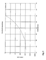
- a Night Vision Imaging system is defined as a system that uses image intensifier tubes to produce an enhanced image of a scene in light conditions too low for normal navigation and pilotage.
- Class B NVIS is any NVIS with spectral response characteristics as shown by the curve in figure 2 .
- an illumination unit 10,12,14 may comprise two types of light emitting diodes (LEDs); a first type intended to be used during daylight conditions and a second type intended to be used during night vision conditions.
- the first type the "daylight” diode has a dominating wavelength of the emitted light of 625 nanometres and a half intensity bandwidth of 20 nanometres. A maximum luminance is 1300 1m.
- the second type the "nightlight” diode has a dominating wavelength of the emitted light of 590 nanometres and a half intensity bandwidth of 18 nanometres.
- a maximum luminance is 60 1m.
- One or more diodes of each type may be employed to help achieve enough intensity, in particular for the daylight conditions case.
- the head-up system is provided with a semi-transparent combiner mirror 70, arranged in the field of view of the pilot and that combines light from the environment in front of the pilot with symbolic information generated by an image generating devise using the light of the illumination unit with the diodes of above.
- the combiner is provided with a coating 72.
- the coating of the combiner may advantageously be centred at 625 nanometres and be provided with a half intensity bandwidth of 38 nanometres of the reflection. Experiments have shown that this results in good photopic transmission through the combiner.
- the head up display system works as follows: The coating of the combiner is adjusted to the wavelength of the daylight diode, i.e., light from the daylight diode is reflected at a high percentage and reaches the unaided eye of the pilot at intensity suitable to comfortably read the symbols discernable in the environmental light during daylight conditions.
- the coating 72 of the semi-transparent combiner mirror 70 is arranged to, as described above, only reflect enough light to meet NVIS class B standards and such that enough light, i.e., light of an intensity that makes symbols clearly visible to the pilot when using NVIS class B goggles, is reflected.
- the system may also be provided with a sharp filter at approximately 610-620 nanometres in the ray path after the second diode.
- the filter may preferably be such that it powerfully reduces wavelengths of the nightlight diode corresponding to the centred wavelength of the coating 72 of the combiner mirror 70.
- Such a filter is devised to reduce the transmission of light of longer wavelengths with a factor 1000. The effect is that light of wavelengths risking saturating the image intensifier tubes of the night vision goggles 92 is heavily reduced.
- the daylight diode i.e., the diode for use during daylight conditions, may preferably be a diode with a dominating wavelength of its emitted light of around 610-650 nanometres.
- the dominating wavelength of the daylight diode may be around 625 nanometres.
- the nightlight diode may be a diode with a dominating wavelength of its emitted light of around 570-600 nanometres.
- the dominating wavelength of the nightlight diode may be around 590 nanometres.
- the function of shifting from using the light from daylight diode to using light from the nightlight diode may be achieved by arranging the diodes such that they can be shifted from a first position where the first diode (12) is close to the image generator, to a second position where the second diode (10) is close to the image generator (20).
- the diodes may be arranged opposite each other and with a pivotal mirror arranged between them to mirror light 90 degrees to the side. When shifting, the pivotal mirror is turned 90 degrees to reflect light from the other diode. Corresponding diodes are turned on and off respectively.
- a third way to achieve the shifting may be to let the night time diode light to be injected via an optical fibre into the permanent light path and switch off the daylight diode and turn on the nightlight diode.
- the nightlight diode is chosen with a wavelength that gives enough light through the combiner and does not affect the NVIS capability. Using lower wavelength would not give enough light and a higher wavelength would impair the NVIS capability.
- the red daylight diode is chosen with a wavelength that gives optimum contrast for the eye when used towards most background colours encountered by a pilot and the coating of the combiner is preferably optimized for the daylight diode dominating wavelength to give maximum performance during bright day conditions.
- the image generator display 20 may be of a transmitting type, for example a Liquid Crystal Display (LCD) as shown in fig. 1 , or may be of a reflecting type, for example a Digital Micro-mirror Device (DMD), with corresponding change of the light sources 10, 12 position.
- LCD Liquid Crystal Display
- DMD Digital Micro-mirror Device
- the head-up display optics may comprise optical elements 30-70 in a compact way to combine light rays of the image from the image source with light rays 90 representing the outside terrain such that a combined image reaches an observer's eyes 100.
- the optics may as an alternative be of some other arrangement as known by a person skilled in the art of head up displays.
Landscapes
- Physics & Mathematics (AREA)
- General Physics & Mathematics (AREA)
- Optics & Photonics (AREA)
- Instrument Panels (AREA)
Claims (9)
- Head-Up-Anzeigesystem, das für ein Fahrzeug mit einem Piloten oder Beobachter geeignet ist, der zur Verwendung einer Nachtsichtbrille der NVIS-Klasse B verpflichtet ist, wobei das Head-Up-Anzeigesystem umfasst:eine Beleuchtungseinheit (12, 14), umfassend eine Bildquelle (20),einen haltransparenten Kombinator-Spiegel (70),wobei die Beleuchtungseinheit (12, 14) des Weiteren eine erste Lichtquelle (12) zum Bereitstellen von Licht für die Bildquelle (20) umfasst, diese Bildquelle (20) so angeordnet ist, dass sie ein Bild über eine Projektionslinse (30), einen Diffusor (50) mit einer matten Oberfläche (51) und einen halbtransparenten flachen Klappspiegel (60) auf den halbtransparenten Kombinator-Spiegel (70) projizieren kann, wobei der flache Klappspiegel zwischen einer beabsichtigten Position (100) der Augen des Beobachters und dem halbtransparenten Kombinator-Spiegel (70) angeordnet ist, um das Bild von der Bildquelle (20) in Richtung des halbtransparenten Kombinator-Spiegels (70) zu reflektieren, der halbtransparente Kombinator-Spiegel (70) eine Beschichtung (72) aufweist, die dazu eingerichtet ist, eine Sicht auf die Umgebung vor dem Fahrzeug mit dem projizierten Bild zu überlagern, indem die Lichtstrahlen (90) von der Umgebung durchgelassen werden und gleichzeitig das projizierte Bild in Richtung der Augen (100) eines Beobachters reflektiert wird,dadurch gekennzeichnet, dassdie Bildquelle (20) so angeordnet ist, dass sie Licht von der ersten Lichtquelle (12) in Richtung des Kombinator-Spiegels (70) reflektiert und dadurch, dass die Beleuchtungseinheit (10, 12, 14) des Weiteren eine zweite Lichtquelle (10) umfasst, wobei die Lichtquellen (10, 12) als ein erster bzw. zweiter Typ von Leuchtdiodeneinheiten (LED) ausgeführt sind; wobei der erste Typ zur Verwendung bei Tageslichtbedingungen vorgesehen ist und der zweite Typ zur Verwendung bei Nachtsichtbedingungen vorgesehen ist, der erste Typ, die "Tageslicht-Diode", so eingerichtet ist, dass sie eine dominierende Wellenlänge des emittierten Lichts von 625 Nanometern und eine Halbwertsbreite von 20 Nanometern aufweist, der zweite Typ, die "Nachtlicht-Diode", so eingerichtet ist, dass sie eine dominierende Wellenlänge des emittierten Lichts von 590 Nanometern und eine Halbwertsbreite von 18 Nanometern aufweist, und wobei die Beschichtung (72) des halbtransparenten Kombinator-Spiegels (70) bei 625 Nanometern zentriert ist und über eine Halbwertsbreite der Reflexion von 38 Nanometern verfügt, und wobei eine Luminanzsteuerungseinheit dazu eingerichtet ist, die Helligkeit der bilderzeugenden Anzeige (20) und/oder der aktuell verwendeten Lichtquelle (10, 12) anzupassen, und wobei das System des Weiteren mit einem Schärfefilter bei etwa 610 - 620 Nanometern im Strahlenverlauf nach der zweiten Diode versehen ist, und wobei ein halbtransparenter, flacher Klappspiegel (60) mit einer Beschichtung (62), die auf derselben Wellenlänge wie die Beschichtung (72) des halbtransparenten Kombinator-Spiegels (70) zentriert ist, zwischen der beabsichtigten Position (100) der Augen des Beobachters und dem halbtransparenten Kombinator-Spiegel (70) angeordnet ist, um das Bild von der Bildquelle (20) in Richtung des halbtransparenten Kombinator-Spiegels (70) zu reflektieren,wobei der Filter dazu eingerichtet ist, Wellenlängen der Nachtlicht-Diode, die der zentrierten Wellenlänge der Beschichtung 72 des Kombinator-Spiegels 70 entsprechen, sehr stark zu reduzieren, und außerdem dazu eingerichtet ist, die Durchlässigkeit für Licht mit längeren Wellenlängen mit einem Faktor von 1000 zu reduzieren.
- Head-Up-Anzeigesystem nach Anspruch 1, wobei der halbtransparente Kombinator-Spiegel (70) sphärisch oder asphärisch ist.
- Head-Up-Anzeigesystem nach Anspruch 2, wobei der halbtransparente Kombinator-Spiegel (70) sphärisch ist.
- Head-Up-Anzeigesystem nach Anspruch 1, wobei der halbtransparente, flache Klappspiegel (60) mit einer Beschichtung (62) versehen ist, die auf derselben Wellenlänge wie die Beschichtung (72) des halbtransparenten Kombinator-Spiegels (70) zentriert ist.
- Head-Up-Anzeigesystem nach einem der Ansprüche 1 bis 4, wobei die Tageslicht-Diode eine Luminanz von 1300 Im aufweist.
- Head-Up-Anzeigesystem nach einem der Ansprüche 1 bis 5, wobei die Nachtlicht-Diode eine Luminanz von 60 Im aufweist.
- Head-Up-Anzeigesystem nach einem der Ansprüche 1 bis 6, wobei eine oder mehrere Dioden jedes Typs eingesetzt werden können, damit eine ausreichende Intensität erreicht werden kann.
- Head-Up-Anzeigesystem nach einem der Ansprüche 1 bis 7, wobei die zweite Lichtquelle (10) und die Kombinator-Beschichtung (72) so eingerichtet sind, dass sie eine Lichtintensität der zweiten Lichtquelle (10) beim Erreichen der Nachsichtbrille oder des bloßen Auges des Piloten bereitstellen, die, nachdem das Licht von der zweiten Lichtquelle den hablbtransparenten Kombinator-Spiegel (70) passiert hat, etwa 10.000 Mal die Intensität der Lichtwellenlänge von 670 - 930 Nanometern (rot und infrarot) von der Umgebung aufweist.
- Verwendung des Head-Up-Anzeigesystems nach einem der vorhergehenden Ansprüche in Verbindung mit einer Nachtsichtbrille (92) der NVIS-Klasse B.
Priority Applications (3)
| Application Number | Priority Date | Filing Date | Title |
|---|---|---|---|
| ES08170492.6T ES2498671T3 (es) | 2008-12-02 | 2008-12-02 | Dispositivo de visualización "de cabeza alta" para gafas de visión nocturna |
| EP08170492.6A EP2194418B1 (de) | 2008-12-02 | 2008-12-02 | Head-Up-Anzeige für Nachtsichtbrillen |
| US12/629,193 US8730581B2 (en) | 2008-12-02 | 2009-12-02 | Head-up display for night vision goggles |
Applications Claiming Priority (1)
| Application Number | Priority Date | Filing Date | Title |
|---|---|---|---|
| EP08170492.6A EP2194418B1 (de) | 2008-12-02 | 2008-12-02 | Head-Up-Anzeige für Nachtsichtbrillen |
Publications (2)
| Publication Number | Publication Date |
|---|---|
| EP2194418A1 EP2194418A1 (de) | 2010-06-09 |
| EP2194418B1 true EP2194418B1 (de) | 2014-07-02 |
Family
ID=40499451
Family Applications (1)
| Application Number | Title | Priority Date | Filing Date |
|---|---|---|---|
| EP08170492.6A Not-in-force EP2194418B1 (de) | 2008-12-02 | 2008-12-02 | Head-Up-Anzeige für Nachtsichtbrillen |
Country Status (3)
| Country | Link |
|---|---|
| US (1) | US8730581B2 (de) |
| EP (1) | EP2194418B1 (de) |
| ES (1) | ES2498671T3 (de) |
Families Citing this family (28)
| Publication number | Priority date | Publication date | Assignee | Title |
|---|---|---|---|---|
| AU2011220382A1 (en) | 2010-02-28 | 2012-10-18 | Microsoft Corporation | Local advertising content on an interactive head-mounted eyepiece |
| US9229227B2 (en) | 2010-02-28 | 2016-01-05 | Microsoft Technology Licensing, Llc | See-through near-eye display glasses with a light transmissive wedge shaped illumination system |
| US9182596B2 (en) | 2010-02-28 | 2015-11-10 | Microsoft Technology Licensing, Llc | See-through near-eye display glasses with the optical assembly including absorptive polarizers or anti-reflective coatings to reduce stray light |
| US9366862B2 (en) | 2010-02-28 | 2016-06-14 | Microsoft Technology Licensing, Llc | System and method for delivering content to a group of see-through near eye display eyepieces |
| US9341843B2 (en) | 2010-02-28 | 2016-05-17 | Microsoft Technology Licensing, Llc | See-through near-eye display glasses with a small scale image source |
| US9285589B2 (en) | 2010-02-28 | 2016-03-15 | Microsoft Technology Licensing, Llc | AR glasses with event and sensor triggered control of AR eyepiece applications |
| US10180572B2 (en) | 2010-02-28 | 2019-01-15 | Microsoft Technology Licensing, Llc | AR glasses with event and user action control of external applications |
| US9759917B2 (en) | 2010-02-28 | 2017-09-12 | Microsoft Technology Licensing, Llc | AR glasses with event and sensor triggered AR eyepiece interface to external devices |
| US20120249797A1 (en) | 2010-02-28 | 2012-10-04 | Osterhout Group, Inc. | Head-worn adaptive display |
| US20150309316A1 (en) | 2011-04-06 | 2015-10-29 | Microsoft Technology Licensing, Llc | Ar glasses with predictive control of external device based on event input |
| WO2013074684A1 (en) * | 2011-11-15 | 2013-05-23 | Elbit Systems Of America, Llc | System and method for streaming multiple images from a single projector |
| US9671566B2 (en) | 2012-06-11 | 2017-06-06 | Magic Leap, Inc. | Planar waveguide apparatus with diffraction element(s) and system employing same |
| JP5813243B2 (ja) * | 2012-09-27 | 2015-11-17 | パイオニア株式会社 | 表示装置 |
| US20140253605A1 (en) * | 2013-03-05 | 2014-09-11 | John N. Border | Controlling brightness of a displayed image |
| KR102270699B1 (ko) * | 2013-03-11 | 2021-06-28 | 매직 립, 인코포레이티드 | 증강 및 가상 현실을 위한 시스템 및 방법 |
| NZ735751A (en) | 2013-03-15 | 2019-10-25 | Magic Leap Inc | Display system and method |
| CN105247861B (zh) | 2013-03-22 | 2017-11-10 | 精工爱普生株式会社 | 红外视频显示眼镜 |
| WO2014204361A1 (en) * | 2013-06-17 | 2014-12-24 | Saab Ab | Head-up display for night vision goggles |
| CN107111142B (zh) | 2015-01-06 | 2021-04-27 | 伊奎蒂公司 | 具有弯曲的微透镜阵列的头戴式成像装置 |
| EP3405828A1 (de) | 2016-01-22 | 2018-11-28 | Corning Incorporated | Persönliche anzeige mit breitem feld |
| US10317674B2 (en) | 2017-01-31 | 2019-06-11 | City University Of Hong Kong | Augmented reality systems and methods |
| US10976551B2 (en) | 2017-08-30 | 2021-04-13 | Corning Incorporated | Wide field personal display device |
| EP3807702B1 (de) * | 2018-06-15 | 2023-09-13 | Continental Automotive Technologies GmbH | Gerät zum generieren eines virtuellen bildes mit störlichtunterdrückung |
| WO2020047486A1 (en) | 2018-08-31 | 2020-03-05 | Magic Leap, Inc. | Spatially-resolved dynamic dimming for augmented reality device |
| CN110426853B (zh) * | 2019-07-31 | 2020-10-16 | 华为技术有限公司 | 镜片和头戴式显示装置 |
| CN110596897B (zh) * | 2019-09-17 | 2021-12-10 | 北京耐德佳显示技术有限公司 | 一种平视显示设备 |
| CN111123520A (zh) * | 2020-01-10 | 2020-05-08 | 京东方科技集团股份有限公司 | 一种近眼显示装置 |
| DE102021204539A1 (de) * | 2021-05-05 | 2022-11-10 | Continental Automotive Technologies GmbH | Gerät zum Generieren eines virtuellen Bildes mit einstellbarem Kontrast |
Citations (2)
| Publication number | Priority date | Publication date | Assignee | Title |
|---|---|---|---|---|
| US20070171623A1 (en) * | 2006-01-24 | 2007-07-26 | Astronautics Corporation Of America | Night vision compatible display backlight |
| US20070217018A1 (en) * | 2005-12-15 | 2007-09-20 | Saab Ab | Head-up display |
Family Cites Families (5)
| Publication number | Priority date | Publication date | Assignee | Title |
|---|---|---|---|---|
| US6097543A (en) * | 1992-02-07 | 2000-08-01 | I-O Display Systems Llc | Personal visual display |
| US5926265A (en) * | 1997-04-14 | 1999-07-20 | The United States Of America As Represented By The Secretary Of The Air Force | Low-level lighting comparator |
| US7592926B2 (en) * | 2004-03-15 | 2009-09-22 | Sri International | Light-emitting diode assembly for use in heads-up display systems of propeller-driven aircraft |
| DE102006005571A1 (de) | 2006-02-06 | 2007-08-09 | Siemens Ag | Head-Up-Display |
| FR2898586B1 (fr) | 2006-03-15 | 2008-04-18 | Airbus France Sas | Outil d'aide a la conception d'un poste de pilotage d'aeronef compatible avec un systeme de vision nocturne |
-
2008
- 2008-12-02 ES ES08170492.6T patent/ES2498671T3/es active Active
- 2008-12-02 EP EP08170492.6A patent/EP2194418B1/de not_active Not-in-force
-
2009
- 2009-12-02 US US12/629,193 patent/US8730581B2/en not_active Expired - Fee Related
Patent Citations (2)
| Publication number | Priority date | Publication date | Assignee | Title |
|---|---|---|---|---|
| US20070217018A1 (en) * | 2005-12-15 | 2007-09-20 | Saab Ab | Head-up display |
| US20070171623A1 (en) * | 2006-01-24 | 2007-07-26 | Astronautics Corporation Of America | Night vision compatible display backlight |
Also Published As
| Publication number | Publication date |
|---|---|
| EP2194418A1 (de) | 2010-06-09 |
| US20140098425A1 (en) | 2014-04-10 |
| US8730581B2 (en) | 2014-05-20 |
| ES2498671T3 (es) | 2014-09-25 |
Similar Documents
| Publication | Publication Date | Title |
|---|---|---|
| EP2194418B1 (de) | Head-Up-Anzeige für Nachtsichtbrillen | |
| US9470891B2 (en) | Head-up display for night vision goggles | |
| US6574030B1 (en) | Multi-mode display using an electronically controlled mirror | |
| US6379009B1 (en) | Conjugate optics projection display with image enhancement | |
| US9229237B2 (en) | Helmet mounted display system adjustable for bright ambient light conditions | |
| US20070217018A1 (en) | Head-up display | |
| US5157548A (en) | Optical device designed for the introduction of a collimated image into an observer's visual field and enbaling night vision | |
| US9069163B2 (en) | Head-up display with brightness control | |
| US7170057B2 (en) | Image enhancement system and method for night goggles | |
| CA2865223C (en) | System and method for projecting synthetic imagery and scenic imagery using an optical component comprising a diffractive optical element pattern | |
| US10520724B2 (en) | Multi-wavelength head up display systems and methods | |
| CN103003736A (zh) | 显示器,尤其是车辆的平视显示器 | |
| FR2706047A1 (fr) | Système d'affichage de casque. | |
| GB2149140A (en) | Head-up display systems | |
| Rash et al. | The human factor considerations of image intensification and thermal imaging systems | |
| US5734359A (en) | Display system intended to be attached to the head or to a helmet, and a helmet provided with such a display system | |
| EP3407112A1 (de) | Head-up-display (hud) mit verteilter apertur | |
| EP3816708B1 (de) | Lichtsicherheitsverschluss in der erweiterten realität | |
| USH779H (en) | Daytime flight symbology display system | |
| Cameron | Development of the combiner-eyepiece night-vision goggle | |
| NL9401110A (nl) | Weergeefstelsel bestemd voor het superponeren van drie beelden voor het verkrijgen van een gemengd beeld. | |
| Cameron | Integrated night vision in helmet-mounted displays | |
| GB2496878A (en) | Ground use night vision device with a filter with two regions | |
| CA2309562A1 (en) | Improvements in or relating to image intensifiers | |
| CZ35692U1 (cs) | Průhledový displej pro letadlo |
Legal Events
| Date | Code | Title | Description |
|---|---|---|---|
| PUAI | Public reference made under article 153(3) epc to a published international application that has entered the european phase |
Free format text: ORIGINAL CODE: 0009012 |
|
| AK | Designated contracting states |
Kind code of ref document: A1 Designated state(s): AT BE BG CH CY CZ DE DK EE ES FI FR GB GR HR HU IE IS IT LI LT LU LV MC MT NL NO PL PT RO SE SI SK TR |
|
| AX | Request for extension of the european patent |
Extension state: AL BA MK RS |
|
| 17P | Request for examination filed |
Effective date: 20101119 |
|
| R17P | Request for examination filed (corrected) |
Effective date: 20101119 |
|
| 17Q | First examination report despatched |
Effective date: 20110118 |
|
| AKX | Designation fees paid |
Designated state(s): AT BE BG CH CY CZ DE DK EE ES FI FR GB GR HR HU IE IS IT LI LT LU LV MC MT NL NO PL PT RO SE SI SK TR |
|
| GRAP | Despatch of communication of intention to grant a patent |
Free format text: ORIGINAL CODE: EPIDOSNIGR1 |
|
| INTG | Intention to grant announced |
Effective date: 20140204 |
|
| GRAS | Grant fee paid |
Free format text: ORIGINAL CODE: EPIDOSNIGR3 |
|
| GRAA | (expected) grant |
Free format text: ORIGINAL CODE: 0009210 |
|
| AK | Designated contracting states |
Kind code of ref document: B1 Designated state(s): AT BE BG CH CY CZ DE DK EE ES FI FR GB GR HR HU IE IS IT LI LT LU LV MC MT NL NO PL PT RO SE SI SK TR |
|
| REG | Reference to a national code |
Ref country code: GB Ref legal event code: FG4D |
|
| REG | Reference to a national code |
Ref country code: CH Ref legal event code: EP Ref country code: AT Ref legal event code: REF Ref document number: 676199 Country of ref document: AT Kind code of ref document: T Effective date: 20140715 |
|
| REG | Reference to a national code |
Ref country code: IE Ref legal event code: FG4D |
|
| REG | Reference to a national code |
Ref country code: DE Ref legal event code: R096 Ref document number: 602008033072 Country of ref document: DE Effective date: 20140814 |
|
| REG | Reference to a national code |
Ref country code: ES Ref legal event code: FG2A Ref document number: 2498671 Country of ref document: ES Kind code of ref document: T3 Effective date: 20140925 |
|
| REG | Reference to a national code |
Ref country code: AT Ref legal event code: MK05 Ref document number: 676199 Country of ref document: AT Kind code of ref document: T Effective date: 20140702 |
|
| REG | Reference to a national code |
Ref country code: NL Ref legal event code: VDEP Effective date: 20140702 |
|
| REG | Reference to a national code |
Ref country code: LT Ref legal event code: MG4D |
|
| PG25 | Lapsed in a contracting state [announced via postgrant information from national office to epo] |
Ref country code: PT Free format text: LAPSE BECAUSE OF FAILURE TO SUBMIT A TRANSLATION OF THE DESCRIPTION OR TO PAY THE FEE WITHIN THE PRESCRIBED TIME-LIMIT Effective date: 20141103 Ref country code: SE Free format text: LAPSE BECAUSE OF FAILURE TO SUBMIT A TRANSLATION OF THE DESCRIPTION OR TO PAY THE FEE WITHIN THE PRESCRIBED TIME-LIMIT Effective date: 20140702 Ref country code: NO Free format text: LAPSE BECAUSE OF FAILURE TO SUBMIT A TRANSLATION OF THE DESCRIPTION OR TO PAY THE FEE WITHIN THE PRESCRIBED TIME-LIMIT Effective date: 20141002 Ref country code: LT Free format text: LAPSE BECAUSE OF FAILURE TO SUBMIT A TRANSLATION OF THE DESCRIPTION OR TO PAY THE FEE WITHIN THE PRESCRIBED TIME-LIMIT Effective date: 20140702 Ref country code: FI Free format text: LAPSE BECAUSE OF FAILURE TO SUBMIT A TRANSLATION OF THE DESCRIPTION OR TO PAY THE FEE WITHIN THE PRESCRIBED TIME-LIMIT Effective date: 20140702 Ref country code: BG Free format text: LAPSE BECAUSE OF FAILURE TO SUBMIT A TRANSLATION OF THE DESCRIPTION OR TO PAY THE FEE WITHIN THE PRESCRIBED TIME-LIMIT Effective date: 20141002 Ref country code: CZ Free format text: LAPSE BECAUSE OF FAILURE TO SUBMIT A TRANSLATION OF THE DESCRIPTION OR TO PAY THE FEE WITHIN THE PRESCRIBED TIME-LIMIT Effective date: 20140702 Ref country code: GR Free format text: LAPSE BECAUSE OF FAILURE TO SUBMIT A TRANSLATION OF THE DESCRIPTION OR TO PAY THE FEE WITHIN THE PRESCRIBED TIME-LIMIT Effective date: 20141003 |
|
| PG25 | Lapsed in a contracting state [announced via postgrant information from national office to epo] |
Ref country code: PL Free format text: LAPSE BECAUSE OF FAILURE TO SUBMIT A TRANSLATION OF THE DESCRIPTION OR TO PAY THE FEE WITHIN THE PRESCRIBED TIME-LIMIT Effective date: 20140702 Ref country code: LV Free format text: LAPSE BECAUSE OF FAILURE TO SUBMIT A TRANSLATION OF THE DESCRIPTION OR TO PAY THE FEE WITHIN THE PRESCRIBED TIME-LIMIT Effective date: 20140702 Ref country code: NL Free format text: LAPSE BECAUSE OF FAILURE TO SUBMIT A TRANSLATION OF THE DESCRIPTION OR TO PAY THE FEE WITHIN THE PRESCRIBED TIME-LIMIT Effective date: 20140702 Ref country code: IS Free format text: LAPSE BECAUSE OF FAILURE TO SUBMIT A TRANSLATION OF THE DESCRIPTION OR TO PAY THE FEE WITHIN THE PRESCRIBED TIME-LIMIT Effective date: 20141102 Ref country code: CY Free format text: LAPSE BECAUSE OF FAILURE TO SUBMIT A TRANSLATION OF THE DESCRIPTION OR TO PAY THE FEE WITHIN THE PRESCRIBED TIME-LIMIT Effective date: 20140702 Ref country code: HR Free format text: LAPSE BECAUSE OF FAILURE TO SUBMIT A TRANSLATION OF THE DESCRIPTION OR TO PAY THE FEE WITHIN THE PRESCRIBED TIME-LIMIT Effective date: 20140702 Ref country code: AT Free format text: LAPSE BECAUSE OF FAILURE TO SUBMIT A TRANSLATION OF THE DESCRIPTION OR TO PAY THE FEE WITHIN THE PRESCRIBED TIME-LIMIT Effective date: 20140702 |
|
| REG | Reference to a national code |
Ref country code: DE Ref legal event code: R097 Ref document number: 602008033072 Country of ref document: DE |
|
| PG25 | Lapsed in a contracting state [announced via postgrant information from national office to epo] |
Ref country code: DK Free format text: LAPSE BECAUSE OF FAILURE TO SUBMIT A TRANSLATION OF THE DESCRIPTION OR TO PAY THE FEE WITHIN THE PRESCRIBED TIME-LIMIT Effective date: 20140702 Ref country code: SK Free format text: LAPSE BECAUSE OF FAILURE TO SUBMIT A TRANSLATION OF THE DESCRIPTION OR TO PAY THE FEE WITHIN THE PRESCRIBED TIME-LIMIT Effective date: 20140702 Ref country code: EE Free format text: LAPSE BECAUSE OF FAILURE TO SUBMIT A TRANSLATION OF THE DESCRIPTION OR TO PAY THE FEE WITHIN THE PRESCRIBED TIME-LIMIT Effective date: 20140702 Ref country code: RO Free format text: LAPSE BECAUSE OF FAILURE TO SUBMIT A TRANSLATION OF THE DESCRIPTION OR TO PAY THE FEE WITHIN THE PRESCRIBED TIME-LIMIT Effective date: 20140702 |
|
| PLBE | No opposition filed within time limit |
Free format text: ORIGINAL CODE: 0009261 |
|
| STAA | Information on the status of an ep patent application or granted ep patent |
Free format text: STATUS: NO OPPOSITION FILED WITHIN TIME LIMIT |
|
| 26N | No opposition filed |
Effective date: 20150407 |
|
| PG25 | Lapsed in a contracting state [announced via postgrant information from national office to epo] |
Ref country code: BE Free format text: LAPSE BECAUSE OF NON-PAYMENT OF DUE FEES Effective date: 20141231 |
|
| PG25 | Lapsed in a contracting state [announced via postgrant information from national office to epo] |
Ref country code: LU Free format text: LAPSE BECAUSE OF FAILURE TO SUBMIT A TRANSLATION OF THE DESCRIPTION OR TO PAY THE FEE WITHIN THE PRESCRIBED TIME-LIMIT Effective date: 20141202 |
|
| REG | Reference to a national code |
Ref country code: CH Ref legal event code: PL |
|
| REG | Reference to a national code |
Ref country code: IE Ref legal event code: MM4A |
|
| PG25 | Lapsed in a contracting state [announced via postgrant information from national office to epo] |
Ref country code: LI Free format text: LAPSE BECAUSE OF NON-PAYMENT OF DUE FEES Effective date: 20141231 Ref country code: CH Free format text: LAPSE BECAUSE OF NON-PAYMENT OF DUE FEES Effective date: 20141231 Ref country code: IE Free format text: LAPSE BECAUSE OF NON-PAYMENT OF DUE FEES Effective date: 20141202 |
|
| PG25 | Lapsed in a contracting state [announced via postgrant information from national office to epo] |
Ref country code: SI Free format text: LAPSE BECAUSE OF FAILURE TO SUBMIT A TRANSLATION OF THE DESCRIPTION OR TO PAY THE FEE WITHIN THE PRESCRIBED TIME-LIMIT Effective date: 20140702 |
|
| REG | Reference to a national code |
Ref country code: FR Ref legal event code: PLFP Year of fee payment: 8 |
|
| PG25 | Lapsed in a contracting state [announced via postgrant information from national office to epo] |
Ref country code: MC Free format text: LAPSE BECAUSE OF FAILURE TO SUBMIT A TRANSLATION OF THE DESCRIPTION OR TO PAY THE FEE WITHIN THE PRESCRIBED TIME-LIMIT Effective date: 20140702 |
|
| PG25 | Lapsed in a contracting state [announced via postgrant information from national office to epo] |
Ref country code: TR Free format text: LAPSE BECAUSE OF FAILURE TO SUBMIT A TRANSLATION OF THE DESCRIPTION OR TO PAY THE FEE WITHIN THE PRESCRIBED TIME-LIMIT Effective date: 20140702 Ref country code: HU Free format text: LAPSE BECAUSE OF FAILURE TO SUBMIT A TRANSLATION OF THE DESCRIPTION OR TO PAY THE FEE WITHIN THE PRESCRIBED TIME-LIMIT; INVALID AB INITIO Effective date: 20081202 Ref country code: MT Free format text: LAPSE BECAUSE OF FAILURE TO SUBMIT A TRANSLATION OF THE DESCRIPTION OR TO PAY THE FEE WITHIN THE PRESCRIBED TIME-LIMIT Effective date: 20140702 Ref country code: BE Free format text: LAPSE BECAUSE OF FAILURE TO SUBMIT A TRANSLATION OF THE DESCRIPTION OR TO PAY THE FEE WITHIN THE PRESCRIBED TIME-LIMIT Effective date: 20140702 |
|
| REG | Reference to a national code |
Ref country code: FR Ref legal event code: PLFP Year of fee payment: 9 |
|
| REG | Reference to a national code |
Ref country code: FR Ref legal event code: PLFP Year of fee payment: 10 |
|
| PGFP | Annual fee paid to national office [announced via postgrant information from national office to epo] |
Ref country code: DE Payment date: 20181220 Year of fee payment: 11 |
|
| PGFP | Annual fee paid to national office [announced via postgrant information from national office to epo] |
Ref country code: GB Payment date: 20181217 Year of fee payment: 11 Ref country code: FR Payment date: 20181214 Year of fee payment: 11 |
|
| PGFP | Annual fee paid to national office [announced via postgrant information from national office to epo] |
Ref country code: IT Payment date: 20181220 Year of fee payment: 11 Ref country code: ES Payment date: 20190108 Year of fee payment: 11 |
|
| REG | Reference to a national code |
Ref country code: DE Ref legal event code: R119 Ref document number: 602008033072 Country of ref document: DE |
|
| GBPC | Gb: european patent ceased through non-payment of renewal fee |
Effective date: 20191202 |
|
| PG25 | Lapsed in a contracting state [announced via postgrant information from national office to epo] |
Ref country code: DE Free format text: LAPSE BECAUSE OF NON-PAYMENT OF DUE FEES Effective date: 20200701 Ref country code: GB Free format text: LAPSE BECAUSE OF NON-PAYMENT OF DUE FEES Effective date: 20191202 Ref country code: IT Free format text: LAPSE BECAUSE OF NON-PAYMENT OF DUE FEES Effective date: 20191202 Ref country code: FR Free format text: LAPSE BECAUSE OF NON-PAYMENT OF DUE FEES Effective date: 20191231 |
|
| REG | Reference to a national code |
Ref country code: ES Ref legal event code: FD2A Effective date: 20210601 |
|
| PG25 | Lapsed in a contracting state [announced via postgrant information from national office to epo] |
Ref country code: ES Free format text: LAPSE BECAUSE OF NON-PAYMENT OF DUE FEES Effective date: 20191203 |