EP2194331A2 - Chauffe-eau instantané - Google Patents
Chauffe-eau instantané Download PDFInfo
- Publication number
- EP2194331A2 EP2194331A2 EP09177430A EP09177430A EP2194331A2 EP 2194331 A2 EP2194331 A2 EP 2194331A2 EP 09177430 A EP09177430 A EP 09177430A EP 09177430 A EP09177430 A EP 09177430A EP 2194331 A2 EP2194331 A2 EP 2194331A2
- Authority
- EP
- European Patent Office
- Prior art keywords
- water heater
- coil
- home
- instantaneous water
- radiator
- Prior art date
- Legal status (The legal status is an assumption and is not a legal conclusion. Google has not performed a legal analysis and makes no representation as to the accuracy of the status listed.)
- Withdrawn
Links
- XLYOFNOQVPJJNP-UHFFFAOYSA-N water Substances O XLYOFNOQVPJJNP-UHFFFAOYSA-N 0.000 claims abstract description 34
- 238000010438 heat treatment Methods 0.000 claims abstract description 33
- 230000005291 magnetic effect Effects 0.000 claims abstract description 20
- 238000004804 winding Methods 0.000 claims description 12
- 239000000463 material Substances 0.000 claims description 9
- 229910000859 α-Fe Inorganic materials 0.000 claims description 9
- 239000004020 conductor Substances 0.000 claims description 4
- 238000005406 washing Methods 0.000 claims description 3
- 239000012530 fluid Substances 0.000 claims description 2
- 238000005260 corrosion Methods 0.000 description 9
- 230000007797 corrosion Effects 0.000 description 9
- 230000009969 flowable effect Effects 0.000 description 5
- 230000006698 induction Effects 0.000 description 5
- 235000008733 Citrus aurantifolia Nutrition 0.000 description 4
- 235000011941 Tilia x europaea Nutrition 0.000 description 4
- 239000011248 coating agent Substances 0.000 description 4
- 238000000576 coating method Methods 0.000 description 4
- 230000005294 ferromagnetic effect Effects 0.000 description 4
- 239000003302 ferromagnetic material Substances 0.000 description 4
- 239000004571 lime Substances 0.000 description 4
- XEEYBQQBJWHFJM-UHFFFAOYSA-N Iron Chemical compound [Fe] XEEYBQQBJWHFJM-UHFFFAOYSA-N 0.000 description 2
- 230000005540 biological transmission Effects 0.000 description 2
- 238000006243 chemical reaction Methods 0.000 description 2
- 230000008878 coupling Effects 0.000 description 2
- 238000010168 coupling process Methods 0.000 description 2
- 238000005859 coupling reaction Methods 0.000 description 2
- 238000001035 drying Methods 0.000 description 2
- 230000001939 inductive effect Effects 0.000 description 2
- 239000002184 metal Substances 0.000 description 2
- 229910052751 metal Inorganic materials 0.000 description 2
- CWYNVVGOOAEACU-UHFFFAOYSA-N Fe2+ Chemical compound [Fe+2] CWYNVVGOOAEACU-UHFFFAOYSA-N 0.000 description 1
- 229910000831 Steel Inorganic materials 0.000 description 1
- 238000010521 absorption reaction Methods 0.000 description 1
- 238000010276 construction Methods 0.000 description 1
- 230000001419 dependent effect Effects 0.000 description 1
- 238000010292 electrical insulation Methods 0.000 description 1
- 230000005611 electricity Effects 0.000 description 1
- 238000011010 flushing procedure Methods 0.000 description 1
- 235000013305 food Nutrition 0.000 description 1
- 230000020169 heat generation Effects 0.000 description 1
- 230000002401 inhibitory effect Effects 0.000 description 1
- 238000009434 installation Methods 0.000 description 1
- 229910052742 iron Inorganic materials 0.000 description 1
- 239000007788 liquid Substances 0.000 description 1
- 238000004519 manufacturing process Methods 0.000 description 1
- 150000002739 metals Chemical class 0.000 description 1
- 238000000034 method Methods 0.000 description 1
- 239000012811 non-conductive material Substances 0.000 description 1
- 230000001105 regulatory effect Effects 0.000 description 1
- 229910001220 stainless steel Inorganic materials 0.000 description 1
- 239000010935 stainless steel Substances 0.000 description 1
- 239000010959 steel Substances 0.000 description 1
Images

Classifications
-
- F—MECHANICAL ENGINEERING; LIGHTING; HEATING; WEAPONS; BLASTING
- F24—HEATING; RANGES; VENTILATING
- F24H—FLUID HEATERS, e.g. WATER OR AIR HEATERS, HAVING HEAT-GENERATING MEANS, e.g. HEAT PUMPS, IN GENERAL
- F24H1/00—Water heaters, e.g. boilers, continuous-flow heaters or water-storage heaters
- F24H1/10—Continuous-flow heaters, i.e. heaters in which heat is generated only while the water is flowing, e.g. with direct contact of the water with the heating medium
- F24H1/101—Continuous-flow heaters, i.e. heaters in which heat is generated only while the water is flowing, e.g. with direct contact of the water with the heating medium using electric energy supply
-
- F—MECHANICAL ENGINEERING; LIGHTING; HEATING; WEAPONS; BLASTING
- F24—HEATING; RANGES; VENTILATING
- F24H—FLUID HEATERS, e.g. WATER OR AIR HEATERS, HAVING HEAT-GENERATING MEANS, e.g. HEAT PUMPS, IN GENERAL
- F24H2250/00—Electrical heat generating means
- F24H2250/08—Induction
Definitions
- the invention relates to a home-range instantaneous water heater for passing a flowable medium and with a heater for heating the medium and a household appliance with such a home-range instantaneous water heater.
- the heater may consist of a burner which heats the line with a gas-assisted flame and above that the flowable medium.
- a heating device in the form of a current-carrying resistance wire which heats up and heats the wire wrapped by the resistance wire and above it the medium contained therein.
- JP 2004-135998 Generally known are JP 2004-135998 .
- at least one or more coils for generating the alternating magnetic field are arranged outside the laundry drum. Due to the laundry load of the laundry drum, the laundry drum at a high rotational speed during a spin cycle in vibrations, which run the laundry drum out of control. Due to this, it is disadvantageously required that the induction coils for generating the alternating magnetic field are arranged at a large distance from the drum. In order to heat the drum sufficiently, therefore, correspondingly large electrical currents must be applied to the coils.
- induction furnaces for heating metals are generally known from plant engineering.
- the home-range instantaneous heater has a line with at least one flow channel for passing a flowable medium (liquid and / or gas), as well as a heater for heating the medium, wherein the heating means for generating an alternating magnetic field, a coil and further at least one having the alternating magnetic field heatable radiator.
- Such an arrangement thus exploits that a primary energy, which is provided by the coil as a primary winding, is transmitted by magnetic induction in the secondary-side mounted radiator. Utilizing the transformer or eddy current principle, heat is generated in the radiators and transferred from them to the adjacent medium. By the inductive power transmission from the coil to the radiator, a power loss can be kept low, which can operate such a water heater energy saving.
- the primary energy source (coil) and the radiator or radiators are electrically isolated from each other (galvanically isolated) so that can be dispensed with contacts and cables for the transmission of electricity to the area to be heated.
- a low-priced and more corrosion-resistant construction is achieved.
- electrical components are arranged far away from any fluid-carrying components and thus a contact protection of live parts is ensured, which increases the reliability.
- Another advantage is the possible conversion of the water contained in the "lime" in a lime form, which is no longer on device surfaces such. As radiators, attaches, which further increases the reliability.
- Such a home-range instantaneous water heater can be used in particular in a household appliance such as a hot water instantaneous water heater, a washing machine, a tumble dryer, a washer-dryer or a dishwasher.
- a household appliance such as a hot water instantaneous water heater, a washing machine, a tumble dryer, a washer-dryer or a dishwasher.
- a domestic hot water heater but also household installations such as heating or sanitary concern.
- the at least one heating element can be introduced into the at least one flow channel, since in this way a large-area contact surface with the flow medium can be achieved in a structurally simple manner.
- the at least one radiator may in particular have a plurality of individual radiators, which advantageously leave a sufficient gap for the flow medium. Accordingly, the ratio of the surface, which is in contact with the medium to be heated, and the internal volume of the radiator, adjustable to obtain a high heat transfer rate and thus a low response time.
- individual heaters having a spherical basic shape, since these allow a volume of space and, between the balls, a passage volume for the medium in a particularly advantageous embodiment.
- balls have a relatively smooth and vortex-inhibiting surface.
- the at least one heating element can have an electrically conductive single heating element.
- the single heater may comprise a ferromagnetic material, preferably iron-based (ferrite, steel, etc.).
- the at least one radiator can have at least one secondary winding ("secondary coil”), in particular a short-circuited secondary winding.
- secondary coil By the magnetic alternating field generated by the coil (“primary coil”), a current is generated in the secondary coil, whose winding may have one or more windings, which is converted into heat due to the short circuit.
- a resonant converter is advantageously used.
- the secondary coil has a resistance heating wire as a winding wire.
- the coil may be provided with heating resistors as a load.
- the radiator may have a plurality of individual radiators each having a secondary coil or a plurality of secondary coils.
- the at least one radiator having a coil core of a ferrite-containing material, for. B. in the form of a shell core.
- the coil for generating the alternating magnetic field may be arranged for easy production and obtaining a high reliability outside a wall of the conduit.
- the flow channel is not or at least not substantially shielded for heating the radiator by the wall, the wall is advantageously at least partially or partially formed free of an electrically conductive material, for. B. made of plastic.
- the alternating magnetic field can penetrate substantially undisturbed into the flow region with the at least one heating element located therein.
- the at least one radiator is at least partially formed as a part of the wall.
- a plurality of spaced apart wall sections of a wall of the conduit may be formed as such a radiator, ie electrically conductive, in particular metallic, especially ferromagnetic material.
- An advantage of such arrangements is an external thermal shield, so that the heat generated in the wall regions of the conduit is preferably emitted only in the direction of the medium through which the conduit flows.
- the wall may also have heating, projecting into the at least one flow channel heat transfer elements such as longitudinal ribs, etc.
- the medium may in particular comprise air, water or a lye, as it is used as a working medium or as a heat transfer medium in the home.
- the at least one heating element can come into contact with moisture, ie in particular is arranged within the flow region of the medium, it advantageously has corrosion protection. Corrosion protection is particularly useful, since ferromagnetic materials tend to oxidize or "rusting". In particular, in the case of lines through which water or a liquor flows as the medium, coating on the outside of the radiator with corrosion protection is therefore advantageous.
- at least the flow medium exposed areas of the radiator may consist of a stainless material.
- the conduit is tubular and externally wound with an inductor coil as the coil, and a heating area with the at least one radiator is within the coil-wrapped area in the wall and / or in the at least one flow channel educated.
- FIG. 1 Haus Scheme instantaneous water heater 16, shown by way of example, of a laundry drying apparatus (washer-dryer or tumble dryer) H has a tubular conduit 1.
- the line 1 has a wall 2, which has a flow channel. 3 encloses.
- the outer surface of the wall 2 is wrapped with a coil 5, which generates an alternating magnetic field in the volume enclosed by it upon application of an alternating current and thus serves as an induction coil.
- a flange 4 is formed on the wall 2, which serves as Abloisschutz for a coil 5.
- the wall 2 is made of a non-conductive material, for. As plastic, designed to provide the electromagnetic alternating field generated by the coil 5 as low as possible shielding.
- the individual heaters 6 are made of a material which heats up when the alternating current is applied by means of the coil 5 due to eddy currents induced therein. While the material may generally be an electrically conductive material, particularly a metal, to achieve high efficiency, a ferromagnetic or high ferromagnetic material is used, particularly a corrosion protected ferrous material.
- a control device 8 as control and regulating electronics serves to receive a power provided by a power supply connection 9 and to apply an alternating current to the coil 5 via coil connection lines 10 such that the coil 5 generates the alternating magnetic field in the flow channel 3 in the region of the heating elements 6 and Heating element 6 is heated or heated. When flowing around the heated radiator 6, the medium also warms M.
- a temperature sensor 7 is arranged in or on the flow channel 3, which serves to detect the output temperature of a medium M, which flows through the interior 3 in the direction of the temperature sensor 7 and while the radiator 6 lapped.
- the control device 8 is designed to regulate a temperature by means of a detected by the temperature sensor 7 and applied via a signal line 11 to the control device 8 temperature signal.
- the individual radiator 6 are provided with a corrosion protection 12, which may be formed for example as a coating.
- the line 1 preferably at the two front ends in each case a pipe socket 13, through which the medium M is introduced into the flow channel 3 or discharged on the opposite side of the flow channel 3.
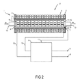
- the water heater 17 off FIG. 2 shows up on the radiator 6 * the same components as the water heater 16 FIG. 1 , why opposite FIG. 1 especially the radiator 6 * is described in detail.
- the individual heaters 19 each have a shell core 14 made of ferrite material, in which a short-circuited secondary winding 15 is housed. While an alternating magnetic field is applied to the secondary windings 15, these are heated and thereby heat the ferrite core 14. The ferrite cores 14 in turn heat the radiator 6 * , and this the flow medium M.
- FIG. 1 a variety of individual radiators can be installed FIG. 1 each be wrapped with secondary windings.
- FIG. 1 an arrangement of a plurality of such bodies can be arranged behind one another or next to one another in the interior 3.
- the individual radiator shown as an example FIG. 1 must not be spherical, but may also be shaped differently, z. B. disc-shaped or annular.
- the wall or at least a portion of the wall be configured as the radiator.
- the wall 2 then corresponding electrically conductive, in particular ferromagnetic, sections or is formed as a whole ferromagnetic, so that the alternating magnetic field generated by the coil 5 heats the wall of the line.
- a heat-reflecting and / or heat-insulating layer is preferably arranged on the outside of the wall, in order to allow as complete a transfer of the heat as possible in the direction of the interior and of the medium.
- the coil does not necessarily have to be wound around the line 1, but in principle can also be configured from a multiplicity of individual coil conductors arranged laterally on the wall or adjacent to the wall.
- the coil may, with a corresponding electrical insulation, also be disposed within the wall or be integrated into the wall, for. B. be poured.
- the coils and coil cores can be configured differently, for. B. with a material other than a ferrite for a bobbin.
- a corrosion coating can already be the base material corrosion resistant, z. As stainless steel, and it can be dispensed with a coating.
Landscapes
- Engineering & Computer Science (AREA)
- Physics & Mathematics (AREA)
- Thermal Sciences (AREA)
- Chemical & Material Sciences (AREA)
- Combustion & Propulsion (AREA)
- Mechanical Engineering (AREA)
- General Engineering & Computer Science (AREA)
- General Induction Heating (AREA)
- Steam Or Hot-Water Central Heating Systems (AREA)
- Instantaneous Water Boilers, Portable Hot-Water Supply Apparatuses, And Control Of Portable Hot-Water Supply Apparatuses (AREA)
Applications Claiming Priority (1)
| Application Number | Priority Date | Filing Date | Title |
|---|---|---|---|
| DE200810044280 DE102008044280A1 (de) | 2008-12-02 | 2008-12-02 | Hausbereich-Durchlauferhitzer |
Publications (2)
| Publication Number | Publication Date |
|---|---|
| EP2194331A2 true EP2194331A2 (fr) | 2010-06-09 |
| EP2194331A3 EP2194331A3 (fr) | 2015-03-25 |
Family
ID=42062491
Family Applications (1)
| Application Number | Title | Priority Date | Filing Date |
|---|---|---|---|
| EP09177430.7A Withdrawn EP2194331A3 (fr) | 2008-12-02 | 2009-11-30 | Chauffe-eau instantané |
Country Status (2)
| Country | Link |
|---|---|
| EP (1) | EP2194331A3 (fr) |
| DE (1) | DE102008044280A1 (fr) |
Cited By (5)
| Publication number | Priority date | Publication date | Assignee | Title |
|---|---|---|---|---|
| WO2015110241A1 (fr) * | 2014-01-23 | 2015-07-30 | Siemens Aktiengesellschaft | Dispositif et procédé pour chauffer un fluide |
| CN114364074A (zh) * | 2022-01-27 | 2022-04-15 | 天津市龙津科技有限公司 | 一种多级串联式高效液体电磁加热系统 |
| CN114753110A (zh) * | 2022-03-25 | 2022-07-15 | 安徽省宁国市天成科技发展有限公司 | 一种电加热装置 |
| US20220265084A1 (en) * | 2019-06-18 | 2022-08-25 | Rheavendors Services S.P.A. | Continuous-flow electromagnetic-induction fluid heater in a beverage vending machine |
| US20240361038A1 (en) * | 2023-04-28 | 2024-10-31 | Robert J. Zwerling | Inductive intelligent water heater |
Families Citing this family (9)
| Publication number | Priority date | Publication date | Assignee | Title |
|---|---|---|---|---|
| DE102010029075A1 (de) | 2010-05-18 | 2011-11-24 | BSH Bosch und Siemens Hausgeräte GmbH | Wäschebehandlungsgerät und Verfahren zum Betreiben eines Wäschebehandlungsgeräts |
| DE102013211579A1 (de) * | 2013-06-19 | 2014-12-24 | Behr Gmbh & Co. Kg | Wärmetauschereinrichtung und Heizvorrichtung |
| DE102013211581A1 (de) * | 2013-06-19 | 2014-12-24 | Behr Gmbh & Co. Kg | Heizvorrichtung |
| DE102013211563A1 (de) * | 2013-06-19 | 2014-12-24 | Behr-Hella Thermocontrol Gmbh | Heizvorrichtung |
| DE102013211559A1 (de) * | 2013-06-19 | 2014-12-24 | Behr-Hella Thermocontrol Gmbh | Heizvorrichtung |
| CN106016693B (zh) * | 2016-06-24 | 2021-07-02 | 沈阳永磁电机制造有限公司 | 一体化永磁涡流加热器 |
| DE102017100564A1 (de) * | 2017-01-12 | 2018-07-12 | Deutsches Zentrum für Luft- und Raumfahrt e.V. | Fluidheizvorrichtung und Verfahren zum Erwärmen eines fluidischen Wärmeträgermediums |
| DE102021203910A1 (de) | 2021-04-20 | 2022-04-21 | Vitesco Technologies GmbH | Induktionsheizvorrichtung sowie elektrische Heizung für ein Fahrzeug |
| EP4636343A1 (fr) | 2024-04-17 | 2025-10-22 | Primetals Technologies Germany GmbH | Système de chauffage avec accumulateur de chaleur à haute température |
Citations (3)
| Publication number | Priority date | Publication date | Assignee | Title |
|---|---|---|---|---|
| US5724750A (en) | 1995-11-16 | 1998-03-10 | Burress; Vergel F. | Clothes dryer with Peltier effect heating, infrared heating, and vacuum drying capabilities |
| JP2004135998A (ja) | 2002-10-21 | 2004-05-13 | Nippon Kouatsu Electric Co | ドラム式衣類乾燥機 |
| JP2005177331A (ja) | 2003-12-22 | 2005-07-07 | Mitsubishi Electric Corp | 洗濯機 |
Family Cites Families (7)
| Publication number | Priority date | Publication date | Assignee | Title |
|---|---|---|---|---|
| US2513242A (en) * | 1945-10-11 | 1950-06-27 | Hollis C Inman | Electric fluid heater |
| GB787125A (en) * | 1952-12-23 | 1957-12-04 | Carl Schorg | Improvements in or relating to apparatus for heating liquids, gases or liquid or gaseous suspensions by electrical induction |
| DE2003133A1 (de) * | 1970-01-24 | 1971-07-29 | Canzler Fa Carl | Vorrichtung zum Erwaermen von durch Rohrleitungen gefuehrtem Rohoel |
| SE442696B (sv) * | 1981-09-24 | 1986-01-20 | Asea Ab | Anordning for vermning av gas- eller vetskeformiga media |
| JPH08264272A (ja) * | 1995-03-27 | 1996-10-11 | Seta Giken:Kk | 電磁誘導加熱装置 |
| JP2004214039A (ja) * | 2003-01-06 | 2004-07-29 | Ono Shokuhin Kogyo Kk | 流体加熱ヒータ |
| CN201110632Y (zh) * | 2007-10-18 | 2008-09-03 | 丁永兵 | 即热式电热水器 |
-
2008
- 2008-12-02 DE DE200810044280 patent/DE102008044280A1/de not_active Withdrawn
-
2009
- 2009-11-30 EP EP09177430.7A patent/EP2194331A3/fr not_active Withdrawn
Patent Citations (3)
| Publication number | Priority date | Publication date | Assignee | Title |
|---|---|---|---|---|
| US5724750A (en) | 1995-11-16 | 1998-03-10 | Burress; Vergel F. | Clothes dryer with Peltier effect heating, infrared heating, and vacuum drying capabilities |
| JP2004135998A (ja) | 2002-10-21 | 2004-05-13 | Nippon Kouatsu Electric Co | ドラム式衣類乾燥機 |
| JP2005177331A (ja) | 2003-12-22 | 2005-07-07 | Mitsubishi Electric Corp | 洗濯機 |
Cited By (7)
| Publication number | Priority date | Publication date | Assignee | Title |
|---|---|---|---|---|
| WO2015110241A1 (fr) * | 2014-01-23 | 2015-07-30 | Siemens Aktiengesellschaft | Dispositif et procédé pour chauffer un fluide |
| US20220265084A1 (en) * | 2019-06-18 | 2022-08-25 | Rheavendors Services S.P.A. | Continuous-flow electromagnetic-induction fluid heater in a beverage vending machine |
| US12268328B2 (en) * | 2019-06-18 | 2025-04-08 | Rheavendors Services S.P.A. | Continuous-flow electromagnetic-induction fluid heater in a beverage vending machine |
| CN114364074A (zh) * | 2022-01-27 | 2022-04-15 | 天津市龙津科技有限公司 | 一种多级串联式高效液体电磁加热系统 |
| CN114753110A (zh) * | 2022-03-25 | 2022-07-15 | 安徽省宁国市天成科技发展有限公司 | 一种电加热装置 |
| CN114753110B (zh) * | 2022-03-25 | 2023-09-08 | 安徽省宁国市天成科技发展有限公司 | 一种电加热装置 |
| US20240361038A1 (en) * | 2023-04-28 | 2024-10-31 | Robert J. Zwerling | Inductive intelligent water heater |
Also Published As
| Publication number | Publication date |
|---|---|
| DE102008044280A1 (de) | 2010-06-10 |
| EP2194331A3 (fr) | 2015-03-25 |
Similar Documents
| Publication | Publication Date | Title |
|---|---|---|
| EP2194331A2 (fr) | Chauffe-eau instantané | |
| EP2350376B1 (fr) | Appareil menager pour l'entretien de pieces de linge avec un dispositif de chauffage et procede de chauffage d'une lessive de lavage et/ou de pieces de linge dans un tambour d'un appareil menager | |
| US20100213190A1 (en) | Flow-through induction heater | |
| EP2838316B1 (fr) | Unité de chauffage à induction | |
| BG60656B1 (bg) | Устройство за нагряване на флуиди | |
| JP5654791B2 (ja) | 過熱水蒸気生成装置 | |
| EP2861914B1 (fr) | Chauffe-eau instantané | |
| DE102009010989A1 (de) | Verfahren und Vorrichtung zur Dampferzeugung | |
| DE3118030C2 (fr) | ||
| KR101190273B1 (ko) | 직렬 연결형 전기 보일러 | |
| EP2388369A2 (fr) | Appareil de traitement du linge et procédé de fonctionnement d'un appareil de traitement du linge | |
| EP0630463B1 (fr) | Chauffe-eau electrique instantane | |
| RU2263418C2 (ru) | Индукционный нагреватель текучих сред | |
| RU2423802C1 (ru) | Устройство индукционного нагрева жидких сред | |
| CN204787186U (zh) | 高频电磁加热多孔管道式热水加热器 | |
| IT201900003373A1 (it) | Dispositivo per il riscaldamento di liquidi. | |
| KR101966400B1 (ko) | 자기유도열을 이용한 유체 보일러 | |
| CN105444141B (zh) | 流体加热装置 | |
| DE4208675C2 (de) | Elektrischer Durchlauferhitzer | |
| DE4201775C2 (de) | Vorrichtung zur niederfrequenten induktiven Durchlauferwärmung eines Fluids mit elektrolytischer Leitfähigkeit | |
| EP0876081B1 (fr) | Elément de chauffage tubulaire incorporant une protection contre une surchauffe | |
| CN106455179A (zh) | 一种电磁线圈绕组及具有其的热水器、液体加热装置 | |
| DE563690C (de) | Ruehrwerksbehaelter mit elektrisch beheiztem Ruehrwerk | |
| KR20090079421A (ko) | 고주파 간접유도가열장치 | |
| AT9617U1 (de) | Strahlungsminderung und energieeinsparung von elektromagnetischen wechselfeldern bei elektrisch betriebenen geräten und anlagen |
Legal Events
| Date | Code | Title | Description |
|---|---|---|---|
| PUAI | Public reference made under article 153(3) epc to a published international application that has entered the european phase |
Free format text: ORIGINAL CODE: 0009012 |
|
| AK | Designated contracting states |
Kind code of ref document: A2 Designated state(s): AT BE BG CH CY CZ DE DK EE ES FI FR GB GR HR HU IE IS IT LI LT LU LV MC MK MT NL NO PL PT RO SE SI SK SM TR |
|
| AX | Request for extension of the european patent |
Extension state: AL BA RS |
|
| PUAL | Search report despatched |
Free format text: ORIGINAL CODE: 0009013 |
|
| AK | Designated contracting states |
Kind code of ref document: A3 Designated state(s): AT BE BG CH CY CZ DE DK EE ES FI FR GB GR HR HU IE IS IT LI LT LU LV MC MK MT NL NO PL PT RO SE SI SK SM TR |
|
| AX | Request for extension of the european patent |
Extension state: AL BA RS |
|
| RAP1 | Party data changed (applicant data changed or rights of an application transferred) |
Owner name: BSH HAUSGERAETE GMBH |
|
| RIC1 | Information provided on ipc code assigned before grant |
Ipc: F24H 1/10 20060101AFI20150219BHEP |
|
| 17P | Request for examination filed |
Effective date: 20150925 |
|
| RBV | Designated contracting states (corrected) |
Designated state(s): AT BE BG CH CY CZ DE DK EE ES FI FR GB GR HR HU IE IS IT LI LT LU LV MC MK MT NL NO PL PT RO SE SI SK SM TR |
|
| STAA | Information on the status of an ep patent application or granted ep patent |
Free format text: STATUS: THE APPLICATION IS DEEMED TO BE WITHDRAWN |
|
| 18D | Application deemed to be withdrawn |
Effective date: 20150926 |