EP2194183B1 - Dryer with recirculation component and method for its operation - Google Patents
Dryer with recirculation component and method for its operation Download PDFInfo
- Publication number
- EP2194183B1 EP2194183B1 EP09175927A EP09175927A EP2194183B1 EP 2194183 B1 EP2194183 B1 EP 2194183B1 EP 09175927 A EP09175927 A EP 09175927A EP 09175927 A EP09175927 A EP 09175927A EP 2194183 B1 EP2194183 B1 EP 2194183B1
- Authority
- EP
- European Patent Office
- Prior art keywords
- air channel
- lint
- dryer
- grill
- air
- Prior art date
- Legal status (The legal status is an assumption and is not a legal conclusion. Google has not performed a legal analysis and makes no representation as to the accuracy of the status listed.)
- Not-in-force
Links
Images

Classifications
-
- D—TEXTILES; PAPER
- D06—TREATMENT OF TEXTILES OR THE LIKE; LAUNDERING; FLEXIBLE MATERIALS NOT OTHERWISE PROVIDED FOR
- D06F—LAUNDERING, DRYING, IRONING, PRESSING OR FOLDING TEXTILE ARTICLES
- D06F58/00—Domestic laundry dryers
- D06F58/20—General details of domestic laundry dryers
- D06F58/206—Heat pump arrangements
-
- D—TEXTILES; PAPER
- D06—TREATMENT OF TEXTILES OR THE LIKE; LAUNDERING; FLEXIBLE MATERIALS NOT OTHERWISE PROVIDED FOR
- D06F—LAUNDERING, DRYING, IRONING, PRESSING OR FOLDING TEXTILE ARTICLES
- D06F58/00—Domestic laundry dryers
- D06F58/20—General details of domestic laundry dryers
- D06F58/22—Lint collecting arrangements
-
- D—TEXTILES; PAPER
- D06—TREATMENT OF TEXTILES OR THE LIKE; LAUNDERING; FLEXIBLE MATERIALS NOT OTHERWISE PROVIDED FOR
- D06F—LAUNDERING, DRYING, IRONING, PRESSING OR FOLDING TEXTILE ARTICLES
- D06F58/00—Domestic laundry dryers
- D06F58/20—General details of domestic laundry dryers
- D06F58/24—Condensing arrangements
Definitions
- the invention relates to a dryer with a drying chamber for objects to be dried, a supply air duct, a process air duct in which there is a heater for heating process air and the heated process air are guided by means of a blower over the objects to be dried and passed through an exhaust duct to the exhaust air outlet can be, wherein the process air duct between the drying chamber and the exhaust air outlet at a branch a recirculating air duct branches to the heater and the remaining part of the process air duct leads as exhaust duct to the exhaust air outlet, and a preferred method for its operation.
- the invention relates in particular to dryers, which are domestic appliances, that is appliances for managing a private household.
- dryers which are domestic appliances, that is appliances for managing a private household.
- Such home appliances are known in particular as tumble dryers, washer-dryers and dishwashers.
- a tumble dryer is operated as an exhaust air dryer or condensation dryer.
- air smoke (so-called "process air”) is drawn from an environment into the exhaust air dryer;
- this air is heated and passed for the purpose of absorbing moisture to the laundry items to be dried and then discharged from the exhaust air dryer. Since this exhaust air is heavily saturated with moisture, it must not be released into a building where the exhaust air dryer is installed. Instead, the exhaust air must be removed from the building through a suitable ventilation system.
- a suitable ventilation system In the simplest case serves a to be connected to the exhaust air dryer exhaust hose, which is connected to a stationary ventilation system or suspended from a window of the building.
- a condensation dryer the operation of which is based on the condensation of moisture evaporated from the laundry by means of warm process air conducted in a closed process air cycle, does not require an exhaust hose. It also allows relatively easy energy recovery from the heated process air, for example by using a heat pump. The condensate produced in the condensation dryer is collected and either pumped off or disposed of by manually emptying a collection container. In an exhaust air dryer, the air laden with moisture after passing through a laundry drum is generally discharged from the dryer. A heat recovery does not take place here.
- the tumble dryer consists of a container receiving and moving the laundry, into which a supply air flow heated by a heating element opens, while the moist hot air is conducted as exhaust air via an outlet.
- a heat exchanger is arranged in front of the heating element, which is flowed through by the moist hot exhaust air from the container.
- the energy efficiency of an exhaust air dryer can according to the already mentioned font WO 2008/110449 A1 be improved by a recirculation system.
- the process air laden with moisture from the laundry in the drying chamber is partially returned to the drying process via the heater.
- the disadvantage here is that very many of the laundry in the drying chamber resulting lint can reach the heating. This can lead to a flurry of the downstream airways including the heating.
- the danger of fire and fire increase, since the lint can ignite at the heater and get to the laundry in the drying chamber.
- Another disadvantage is that due to the higher relative humidity of the exhaust air and the process-related low outward, eg in the installation room, guided process air flow significantly more condensate in the usually long exhaust duct is formed and deposit more lint in the exhaust duct.
- the font DE 86 05 014 U1 describes a device for automatically cleaning a lint filter, which is arranged in a screen housing and in a through the
- the lint filter Retains screen housing and the lint filter conducted lint contained lint, the lint filter is movably mounted.
- an opening is provided, which is closable with a movable lid.
- the lint filter can be moved into this opening and there are devices that generate a cleaning air flow from the back through the lint filter.
- the cleaning of a lint filter is thus effected by the fact that the lint filter is traversed in the opposite direction of air, so that adherent lint be transported to the outside.
- the font US 1 427 580 A describes a clothes dryer with a heating chamber, a drying chamber in connection with the heating chamber and an exhaust air connection, a fan and a housing for this purpose.
- a rotary flap on which there is a sieve.
- the rotary flap can be adjusted so that two passages are closed in such a way that the air flow in the dryer flows through the screen in opposite directions.
- the lint collected in a first position of the sieve is directed in a second position of the sieve by the air flow into an exhaust air chamber.
- the invention thus relates to a dryer with a drying chamber for objects to be dried, a supply air duct, a process air duct, in which a Heating for heating process air is located and the heated process air by means of a blower over the objects to be dried and can be performed via an exhaust duct to the exhaust air outlet, wherein the process air duct between the drying chamber and the exhaust outlet at a branch a recirculation channel branches off to the heater and the remaining Part of the process air duct as the exhaust duct leads to the exhaust air outlet, wherein at the junction a two-part shutter mechanism, comprising a lint grid with a first surface and a second surface and a flap is disposed, wherein the lint and the flap can be rotated against each other so that in a first position of the shutter mechanism, the flap separates the recirculation air duct from the process air duct and the lattice grate the exhaust duct from the process air duct, so that coming from the drying chamber process air exclusively through the fluff
- the recirculating air channel unites before the heating with the supply air duct.
- a maximum volume of air for the introduction of heat energy is tapped, whereby the occurrence of unacceptably high temperatures is excluded in the best possible way.
- the lattice and flap can be adjusted depending on or independently.
- the adjustment of the fluff grid and / or the flap can be made for example with a motor or using a magnet or thermo-actuator.
- the adjustment of the lint and / or the flap can be performed manually by a user of the dryer or automatically.
- a cleaning requirement for a lattice can be determined and this cleaning need to be communicated to a user of the dryer by means of an optical and / or acoustic display device on the dryer.
- the user can then manually adjust the lattice grate and / or flap and thus possibly cause a cleaning of the lattice of adhering fluff.
- an adjustment of the lattice grid and / or flap and thus, if necessary, a cleaning of the lattice structure of adhering lint can be initiated automatically, generally with the aid of program control of the dryer.
- Fluff grate and flap preferably form an angle of 90 °.
- the lattice grid and flap are usually firmly connected.
- the lattice grid and flap are rotatable about a common axis.
- the lattice grille is removable and can be cleaned separately.
- the lattice grate comprises a frame part which is seated in the closure device and a removable lint filter
- the dryer according to the invention preferably comprises at least one heat exchanger. In this way, possibilities for the recovery of heat in the dryer according to the invention are developed.
- the at least one heat exchanger is a heat sink and a heat source of a heat pump.
- any heat pump can be used.
- the cooling of the warm, moisture-laden process air essentially takes place in the heat sink of the heat pump.
- the heat thus transferred into the heat pump passes, usually at elevated temperature, to the heat source of the heat pump, where heat is released, which is used in particular for heating the process air or supply air before entering the drying chamber.
- the heat released in the heat source in the supply air duct for heating supply air or after combination of supply air duct and recirculation duct for heating the combined supply air and exhaust air can be used.
- the recirculating air duct is preferably designed such that it permits a branching off of a proportion of 30% by volume to 75% by volume, particularly preferably about 60% by volume, of a process air flow in the process air duct after the exit from the drying chamber.
- the invention also relates to a method for operating a dryer with a drying chamber for objects to be dried, a supply air duct, a process air duct in which there is a heater for heating process air and the heated process air are guided by means of a blower over the objects to be dried, and can be performed via an exhaust duct to the exhaust air outlet, wherein the process air duct between the drying chamber and the exhaust outlet at a branch a recirculation duct for heating branches off and the remaining part of the process air duct leads as exhaust duct to the exhaust outlet, wherein at the junction a two-piece locking mechanism, comprising a lint with a first surface and a second surface and a flap is arranged, wherein the lint grid and the flap can be rotated against each other so that in a first position of the shutter mechanism, the flap the recirculation passage from Process air channel separates and the lattice grate the exhaust air duct from the process air duct, so that coming from the drying chamber process air continues to flow through the
- the air flow in the exhaust duct is significantly increased, so that lint can be better transported to the outside. Consequently can be reduced in the exhaust duct condensate formation and lint removal can be improved.
- a portion of 30 vol .-% to 75 vol .-% of a process air flow in the process air duct after the exit from the drying chamber in the recirculating air duct is passed.
- the drum inlet temperature may remain within the allowable range.
- the air flow of the exhaust air, the circulating air and / or the supply air can be regulated, for example by using a first controllable closure device in the circulating air duct and / or a second controllable closure device in the supply air duct.
- the amount of supply air can be controlled by the second controllable closure device in the supply air duct so that the supply of supply air is stopped and is operated only with circulating air as process air.
- exhaust air and supply air are each guided through the corresponding heat exchangers in a crossflow or countercurrent process.
- the long arrows indicate the flow direction of the process air and the short arrows indicate the flow direction of a refrigerant.
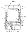
- the in Fig. 1 shown dryer 1 has a drum rotatable about a horizontal axis as a drying chamber 3, are mounted within which driver 4 for moving laundry during a drum rotation.
- Process air is conducted by means of a blower 12 via an electric heater 11, through a drum 3, in a process air duct 2.
- the process air channel 2 is supplied via a supply air duct 15 room air or sucked in by the blower 12.
- the moist, warm process air is split at a branch 19 into a circulating air flow in a recirculating air duct 14 and into an exhaust air flow in an exhaust air duct 13.
- the exhaust duct 13 is an air-to-air heat exchanger 23, in which the process air (here: exhaust air) cooled and is passed to the exhaust air outlet 16 after condensation of the moisture contained in it.
- a closure mechanism 20 comprising a first lint filter 21 and a flap 24.
- Lint filter 21 and flap 24 form an angle of 90 ° and are rotatable about a common axis of rotation 25.
- the dryer 1 In the dryer 1 is heated by the heater 11 from the rear air, ie from a door 5 opposite side of the drum 3, passed through the perforated bottom in the drum 3, comes there with the laundry to be dried in contact and flows through the filling of the Drum 3 to a second lint filter 6 within a closing the filling opening door 5. Subsequently, the process air flow in the door. 5 deflected downwards.
- the process air is essentially supplied in an exhaust duct 13 to the air-air heat exchanger 23, in which the warm, laden with moisture process air is cooled and then fed to an exhaust air outlet 16.
- the separated moisture is collected in a condensate pan 17, from where it can be removed, for example by pumping.
- room air supplied to the dryer 1 is used in the air-air heat exchanger 23 via the supply air duct 15.
- This supply air is heated by the warm, laden with moisture process air and then before entering the drying chamber 3 by means of the electric heater 11.
- a portion of the exiting from the drying chamber 3 warm, laden with moisture process air is diverted into a recirculating air duct 14 and fed through the electric heater 11 in turn into the drying chamber 3.
- the diverted process air from the recirculating air duct 14 and the supply air preheated in the air-air heat exchanger 23 are combined in front of the electric heater 11.
- the supply air flow can be regulated by an adjustable closure device 18 (for example, flaps 18).
- Fig. 3 shows an enlarged detail of a dryer 1, in which the closure device is shown in greater detail.
- a closure mechanism 20 comprising a first lint filter 21 having a first surface 22 and a second surface 23 and a flap 24.
- Lint filter 21 and flap 24 form an angle of 90 ° and are rotatable about a common axis of rotation 25.
- the lattice grate 21 separates the recirculating air channel 14 from the process air channel 2, so that process air coming from the drying chamber 3 can flow both through the lattice 21 through the recirculating air channel 14 and through the exhaust air channel 13.
Abstract
Description
Die Erfindung betrifft einen Trockner mit einer Trocknungskammer für zu trocknende Gegenstände, einem Zuluftkanal, einem Prozessluftkanal, in dem sich eine Heizung zur Erwärmung von Prozessluft befindet und die erwärmte Prozessluft mittels eines Gebläses über die zu trocknenden Gegenstände geführt werden und über einen Abluftkanal zum Abluftausgang geführt werden kann, wobei vom Prozessluftkanal zwischen der Trocknungskammer und dem Abluftausgang an einer Abzweigung ein Umluftkanal zur Heizung abzweigt und der verbleibende Teil des Prozessluftkanals als Abluftkanal zum Abluftausgang führt, sowie ein bevorzugtes Verfahren zu seinem Betrieb.The invention relates to a dryer with a drying chamber for objects to be dried, a supply air duct, a process air duct in which there is a heater for heating process air and the heated process air are guided by means of a blower over the objects to be dried and passed through an exhaust duct to the exhaust air outlet can be, wherein the process air duct between the drying chamber and the exhaust air outlet at a branch a recirculating air duct branches to the heater and the remaining part of the process air duct leads as exhaust duct to the exhaust air outlet, and a preferred method for its operation.
Ein derartiger Ablufttrockner sowie Hinweise zu Verfahren für seinen Betrieb sind der Schrift
Die Erfindung bezieht sich insbesondere auf Trockner, welche Hausgeräte, das heißt Geräte zur Führung eines privaten Haushalts, sind. Solche Hausgeräte sind insbesondere bekannt als Wäschetrockner, Waschtrockner und Spülmaschinen.The invention relates in particular to dryers, which are domestic appliances, that is appliances for managing a private household. Such home appliances are known in particular as tumble dryers, washer-dryers and dishwashers.
Im Allgemeinen wird ein Wäschetrockner als Ablufttrockner oder Kondensationstrockner betrieben. Für eine Trocknungsvorgang in einem Ablufttrockner wird Luft (sogenannte "Prozessluft") aus einer Umgebung in den Ablufttrockner gezogen; im Ablufttrockner wird diese Luft erwärmt und zwecks Aufnehmen von Feuchtigkeit an den zu trocknenden Wäschestücken vorbeigeführt und anschließend aus dem Ablufttrockner entlassen. Da diese Abluft stark mit Feuchtigkeit gesättigt ist, darf sie nicht einfach in ein Gebäude, in welchem der Ablufttrockner aufgestellt ist, entlassen werden. Die Abluft muss vielmehr durch ein geeignetes Lüftungssystem aus dem Gebäude abgeführt werden. Im einfachsten Fall dient dazu ein an den Ablufttrockner anzuschließender Abluftschlauch, welcher mit einem stationären Lüftungssystem verbunden oder aus einem Fenster des Gebäudes herausgehängt wird. Ein Kondensationstrockner, dessen Funktionsweise auf der Kondensation der mittels warmer, in einem geschlossenen Prozessluftkreis geführter Prozessluft verdampften Feuchtigkeit aus der Wäsche beruht, benötigt keinen Abluftschlauch. Er ermöglicht auch relativ einfach eine Energierückgewinnung aus der erwärmten Prozessluft, beispielsweise durch Verwendung einer Wärmepumpe. Das im Kondensationstrockner anfallende Kondensat wird gesammelt und entweder abgepumpt oder durch manuelles Entleeren eines Auffangbehälters entsorgt. Bei einem Ablufttrockner wird im Allgemeinen die nach dem Durchgang durch eine Wäschetrommel mit Feuchtigkeit beladene Luft aus dem Trockner geleitet. Eine Wärmerückgewinnung findet hierbei nicht statt.In general, a tumble dryer is operated as an exhaust air dryer or condensation dryer. For a drying process in an exhaust air dryer, air (so-called "process air") is drawn from an environment into the exhaust air dryer; In the exhaust air dryer, this air is heated and passed for the purpose of absorbing moisture to the laundry items to be dried and then discharged from the exhaust air dryer. Since this exhaust air is heavily saturated with moisture, it must not be released into a building where the exhaust air dryer is installed. Instead, the exhaust air must be removed from the building through a suitable ventilation system. In the simplest case serves a to be connected to the exhaust air dryer exhaust hose, which is connected to a stationary ventilation system or suspended from a window of the building. A condensation dryer, the operation of which is based on the condensation of moisture evaporated from the laundry by means of warm process air conducted in a closed process air cycle, does not require an exhaust hose. It also allows relatively easy energy recovery from the heated process air, for example by using a heat pump. The condensate produced in the condensation dryer is collected and either pumped off or disposed of by manually emptying a collection container. In an exhaust air dryer, the air laden with moisture after passing through a laundry drum is generally discharged from the dryer. A heat recovery does not take place here.
Ein Ablufttrockner mit Wärmerückgewinnung ist bekannt. So beschreibt die Offenlegungsschrift
Die Energieeffizienz eines Ablufttrockners kann entsprechend der bereits erwähnten Schrift
Aus den Dokumenten
Die Schrift
Siebgehäuse und das Flusensieb geleiteten Luftstrom enthaltenen Flusen zurückhält, wobei das Flusensieb beweglich gelagert ist. Im Siebgehäuse ist eine Öffnung vorgesehen, die mit einem beweglichen Deckel verschließbar ist. Das Flusensieb ist in diese Öffnung verbringbar und es sind Einrichtungen vorhanden, die einen Reinigungsluftstrom von der Rückseite durch das Flusensieb erzeugen. Die Reinigung eines Flusensiebes wird somit dadurch bewirkt, dass das Flusensieb in entgegen gesetzter Richtung von Luft durchströmt wird, so dass anhaftende Flusen nach außen befördert werden.Retains screen housing and the lint filter conducted lint contained lint, the lint filter is movably mounted. In the sieve housing an opening is provided, which is closable with a movable lid. The lint filter can be moved into this opening and there are devices that generate a cleaning air flow from the back through the lint filter. The cleaning of a lint filter is thus effected by the fact that the lint filter is traversed in the opposite direction of air, so that adherent lint be transported to the outside.
Die Schrift
Eine Aufgabe der vorliegenden Erfindung ist es daher, einen Ablufttrockner mit hoher Energieeffizienz bereitzustellen, der einen Anteil an Umluft benutzt und bei dem die oben beschriebenen Nachteile überwunden werden können.It is therefore an object of the present invention to provide an exhaust air dryer with high energy efficiency, which uses a proportion of circulating air and in which the disadvantages described above can be overcome.
Die Lösung dieser Aufgabe wird nach dieser Erfindung erreicht durch einen Kondensationstrockner mit den Merkmalen des entsprechenden unabhängigen Patentanspruchs sowie das Verfahren des entsprechenden unabhängigen Patentanspruchs. Bevorzugte Ausführungsformen des erfindungsgemäßen Kondensationstrockners sind in entsprechenden abhängigen Patentansprüchen aufgeführt. Bevorzugten Ausführungsformen des erfindungsgemäßen Kondensationstrockners entsprechen bevorzugte Ausführungsformen des erfindungsgemäßen Verfahrens und umgekehrt, auch wenn dies hierin nicht explizit festgestellt ist.The solution of this object is achieved according to this invention by a condensation dryer with the features of the corresponding independent claim and the method of the corresponding independent claim. Preferred embodiments of the condensation dryer according to the invention are listed in corresponding dependent claims. Preferred embodiments of the condensation dryer according to the invention correspond to preferred embodiments of the method according to the invention and vice versa, although this is not explicitly stated herein.
Gegenstand der Erfindung ist somit ein Trockner mit einer Trocknungskammer für zu trocknende Gegenstände, einem Zuluftkanal, einem Prozessluftkanal, in dem sich eine Heizung zur Erwärmung von Prozessluft befindet und die erwärmte Prozessluft mittels eines Gebläses über die zu trocknenden Gegenstände geführt werden und über einen Abluftkanal zum Abluftausgang geführt werden kann, wobei vom Prozessluftkanal zwischen der Trocknungskammer und dem Abluftausgang an einer Abzweigung ein Umluftkanal zur Heizung abzweigt und der verbleibende Teil des Prozessluftkanals als Abluftkanal zum Abluftausgang führt, wobei an der Abzweigung ein zweiteiliger Verschlussmechanismus, umfassend ein Flusengitter mit einer ersten Oberfläche und einer zweiten Oberfläche sowie eine Klappe, angeordnet ist, wobei das Flusengitter und die Klappe so gegeneinander gedreht werden können, dass in einer ersten Stellung des Verschlussmechanismus die Klappe den Umluftkanal vom Prozessluftkanal trennt und das Flusengitter den Abluftkanal vom Prozessluftkanal, so dass von der Trocknungskammer kommende Prozessluft ausschließlich durch das Flusengitter hindurch durch den Abluftkanal weiterfließt, und in einer zweiten Stellung des Verschlussmechanismus das Flusengitter den Umluftkanal vom Prozessluftkanal trennt, so dass von der Trocknungskammer kommende Prozessluft sowohl durch das Flusengitter hindurch durch den Umluftkanal als auch durch den Abluftkanal fließen kann.The invention thus relates to a dryer with a drying chamber for objects to be dried, a supply air duct, a process air duct, in which a Heating for heating process air is located and the heated process air by means of a blower over the objects to be dried and can be performed via an exhaust duct to the exhaust air outlet, wherein the process air duct between the drying chamber and the exhaust outlet at a branch a recirculation channel branches off to the heater and the remaining Part of the process air duct as the exhaust duct leads to the exhaust air outlet, wherein at the junction a two-part shutter mechanism, comprising a lint grid with a first surface and a second surface and a flap is disposed, wherein the lint and the flap can be rotated against each other so that in a first position of the shutter mechanism, the flap separates the recirculation air duct from the process air duct and the lattice grate the exhaust duct from the process air duct, so that coming from the drying chamber process air exclusively through the fluff grating through the Ablu flows further, and in a second position of the shutter mechanism, the lattice separates the recirculation duct from the process air duct, so that coming from the drying chamber process air can flow both through the lint grid through the circulating air duct and through the exhaust duct.
Vorzugsweise vereinigt sich der Umluftkanal vor der Heizung mit dem Zuluftkanal. Damit wird ein maximales Luftvolumen für die Einbringung der Wärmeenergie erschlossen, wodurch das Auftreten von unzuträglich hohen Temperaturen bestmöglich ausgeschlossen ist.Preferably, the recirculating air channel unites before the heating with the supply air duct. Thus, a maximum volume of air for the introduction of heat energy is tapped, whereby the occurrence of unacceptably high temperatures is excluded in the best possible way.
Es ist erfindungsgemäß bevorzugt, dass Flusengitter und Klappe abhängig oder unabhängig voneinander verstellt werden können. Die Verstellung des Flusengitters und/oder der Klappe kann beispielsweise mit einem Motor oder unter Verwendung eines Magneten oder Thermo-Aktors vorgenommen werden.It is inventively preferred that the lattice and flap can be adjusted depending on or independently. The adjustment of the fluff grid and / or the flap can be made for example with a motor or using a magnet or thermo-actuator.
Überdies kann die Verstellung des Flusengitters und/oder der Klappe manuell durch einen Benutzer des Trockners oder automatisch durchgeführt werden.Moreover, the adjustment of the lint and / or the flap can be performed manually by a user of the dryer or automatically.
Beispielsweise kann in einem Trockner auf an sich bekannte Weise ein Reinigungsbedarf für ein Flusengitter ermittelt werden und dieser Reinigungsbedarf einem Benutzer des Trockners mittels einer optischen und/oder akustischen Anzeigevorrichtung am Trockner mitgeteilt werden. Der Benutzer kann dann manuell eine Verstellung von Flusengitter und/oder Klappe und somit ggf. eine Reinigung des Flusengitters von anhaftenden Flusen veranlassen.For example, in a dryer known per se, a cleaning requirement for a lattice can be determined and this cleaning need to be communicated to a user of the dryer by means of an optical and / or acoustic display device on the dryer. The user can then manually adjust the lattice grate and / or flap and thus possibly cause a cleaning of the lattice of adhering fluff.
Alternativ kann nach einem ermittelten Reinigungsbedarf für ein Flusengitter automatisch, im Allgemeinen unter Zuhilfenahme einer Programmsteuerung des Trockners, eine Verstellung von Flusengitter und/oder Klappe und somit ggf. eine Reinigung des Flusengitters von anhaftenden Flusen veranlasst werden.Alternatively, after a determined cleaning requirement for a lattice grate, an adjustment of the lattice grid and / or flap and thus, if necessary, a cleaning of the lattice structure of adhering lint can be initiated automatically, generally with the aid of program control of the dryer.
Flusengitter und Klappe bilden vorzugsweise einen Winkel von 90°. Hierbei sind Flusengitter und Klappe in der Regel fest miteinander verbunden. Für den Fall, dass von einem gerade verlaufenden Umluftkanal im rechten Winkel ein Abluftkanal abzweigt, kann auf diese Weise auf einfache Weise eine erste Stellung und eine zweite Stellung des Verschlussmechanismus an der Abzweigung realisiert werden.Fluff grate and flap preferably form an angle of 90 °. In this case, the lattice grid and flap are usually firmly connected. In the event that an exhaust air duct branches off at right angles from a straight recirculating air duct, a first position and a second position of the shutter mechanism can be realized at the branch in a simple manner.
Vorzugsweise sind daher Flusengitter und Klappe um eine gemeinsame Achse drehbar.Preferably, therefore, the lattice grid and flap are rotatable about a common axis.
Es kann allerdings vorteilhaft sein, wenn das Flusengitter abnehmbar und getrennt reinigbar ist. In einer bevorzugten Ausführungsform der Erfindung umfasst daher das Flusengitter ein in der Verschlussvorrichtung sitzendes Rahmenteil und einen abnehmbaren FlusenfilterHowever, it can be advantageous if the lattice grille is removable and can be cleaned separately. In a preferred embodiment of the invention, therefore, the lattice grate comprises a frame part which is seated in the closure device and a removable lint filter
Der erfindungsgemäße Trockner umfasst vorzugsweise mindestens einen Wärmetauscher. Auf diese Weise sind Möglichkeiten zur Rückgewinnung von Wärme im erfindungsgemäßen Trockner erschlossen.The dryer according to the invention preferably comprises at least one heat exchanger. In this way, possibilities for the recovery of heat in the dryer according to the invention are developed.
In einer bevorzugten Ausführungsform sind der mindestens eine Wärmetauscher eine Wärmesenke und eine Wärmequelle einer Wärmepumpe. Dabei kann grundsätzlich jede Wärmepumpe verwendet werden. Bei einem mit einer Wärmepumpe ausgestatteten Trockner erfolgt die Kühlung der warmen, mit Feuchtigkeit beladenen Prozessluft im Wesentlichen in der Wärmesenke der Wärmepumpe. Die somit in die Wärmepumpe übertragene Wärme gelangt, in der Regel bei erhöhter Temperatur, zur Wärmequelle der Wärmepumpe, wo Wärme freigesetzt wird, die insbesondere zum Aufheizen der Prozessluft bzw. Zuluft vor Eintritt in die Trocknungskammer verwendet wird. Erfindungsgemäß kann die in der Wärmequelle frei werdende Wärme im Zuluftkanal zur Erwärmung von Zuluft oder nach Vereinigung von Zuluftkanal und Umluftkanal zur Erwärmung der vereinigten Zuluft und Abluft verwendet werden.In a preferred embodiment, the at least one heat exchanger is a heat sink and a heat source of a heat pump. In principle, any heat pump can be used. In a dryer equipped with a heat pump, the cooling of the warm, moisture-laden process air essentially takes place in the heat sink of the heat pump. The heat thus transferred into the heat pump passes, usually at elevated temperature, to the heat source of the heat pump, where heat is released, which is used in particular for heating the process air or supply air before entering the drying chamber. According to the invention, the heat released in the heat source in the supply air duct for heating supply air or after combination of supply air duct and recirculation duct for heating the combined supply air and exhaust air can be used.
Der Umluftkanal ist vorzugsweise so ausgestaltet, dass er eine Abzweigung eines Anteils von 30 Vol.-% bis 75 Vol.-%, besonders bevorzugt etwa 60 Vol-%, eines Prozessluftstroms im Prozessluftkanal nach dem Ausgang aus der Trocknungskammer gestattet.The recirculating air duct is preferably designed such that it permits a branching off of a proportion of 30% by volume to 75% by volume, particularly preferably about 60% by volume, of a process air flow in the process air duct after the exit from the drying chamber.
Gegenstand der Erfindung ist außerdem ein Verfahren zum Betrieb eines Trockners mit einer Trocknungskammer für zu trocknende Gegenstände, einem Zuluftkanal, einem Prozessluftkanal, in dem sich eine Heizung zur Erwärmung von Prozessluft befindet und die erwärmte Prozessluft mittels eines Gebläses über die zu trocknenden Gegenstände geführt werden und über einen Abluftkanal zum Abluftausgang geführt werden kann, wobei vom Prozessluftkanal zwischen der Trocknungskammer und dem Abluftausgang an einer Abzweigung ein Umluftkanal zur Heizung abzweigt und der verbleibende Teil des Prozessluftkanals als Abluftkanal zum Abluftausgang führt, wobei an der Abzweigung ein zweiteiliger Verschlussmechanismus, umfassend ein Flusengitter mit einer ersten Oberfläche und einer zweiten Oberfläche sowie eine Klappe angeordnet ist, wobei das Flusengitter und die Klappe so gegeneinander gedreht werden können, dass in einer ersten Stellung des Verschlussmechanismus die Klappe den Umluftkanal vom Prozessluftkanal trennt und das Flusengitter den Abluftkanal vom Prozessluftkanal, so dass von der Trocknungskammer kommende Prozessluft ausschließlich durch das Flusengitter hindurch durch den Abluftkanal weiterfließt, und in einer zweiten Stellung des Verschlussmechanismus das Flusengitter den Umluftkanal vom Prozessluftkanal trennt, so dass von der Trocknungskammer kommende Prozessluft sowohl durch das Flusengitter hindurch durch den Umluftkanal als auch durch den Abluftkanal fließen kann, bei welchem Verfahren der Verschlussmechanismus von der zweiten Stellung in die erste Stellung gebracht wird, um das Flusengitter von Flusen zu reinigen, indem an der zweiten Oberfläche befindliche Flusen durch die Prozessluft in den Abluftkanal gespült werden.The invention also relates to a method for operating a dryer with a drying chamber for objects to be dried, a supply air duct, a process air duct in which there is a heater for heating process air and the heated process air are guided by means of a blower over the objects to be dried, and can be performed via an exhaust duct to the exhaust air outlet, wherein the process air duct between the drying chamber and the exhaust outlet at a branch a recirculation duct for heating branches off and the remaining part of the process air duct leads as exhaust duct to the exhaust outlet, wherein at the junction a two-piece locking mechanism, comprising a lint with a first surface and a second surface and a flap is arranged, wherein the lint grid and the flap can be rotated against each other so that in a first position of the shutter mechanism, the flap the recirculation passage from Process air channel separates and the lattice grate the exhaust air duct from the process air duct, so that coming from the drying chamber process air continues to flow through the exhaust duct exclusively through the lint, and in a second position of the shutter mechanism the lint can separates the recirculation duct from the process air duct, so that coming from the drying chamber process air both can flow through the lattice through the recirculating air duct as well as through the exhaust duct, in which process the shutter mechanism is moved from the second position to the first position to clean the lint from lint by fluff from the process air at the second surface be flushed the exhaust duct.
In der ersten Stellung des Verschlussmechanismus ist der Luftstrom im Abluftkanal deutlich erhöht, so dass Flusen besser nach außen befördert werden können. Somit können im Abluftkanal die Kondensatbildung reduziert und der Flusenabtransport verbessert werden.In the first position of the closure mechanism, the air flow in the exhaust duct is significantly increased, so that lint can be better transported to the outside. Consequently can be reduced in the exhaust duct condensate formation and lint removal can be improved.
In einer bevorzugten Ausführungsform dieses Verfahrens wird ein Teil von 30 Vol.-% bis 75 Vol.-% eines Prozessluftstroms im Prozessluftkanal nach dem Ausgang aus der Trocknungskammer in den Umluftkanal geleitet.In a preferred embodiment of this method, a portion of 30 vol .-% to 75 vol .-% of a process air flow in the process air duct after the exit from the drying chamber in the recirculating air duct is passed.
Durch die Verwendung eines Umluftkanals bzw. die Durchleitung der heißen, mit Feuchtigkeit beladenen Umluft durch den Umluftkanal zur Heizung wird im Allgemeinen die Lufttemperatur hinter der Heizung bei gleichbleibender Heizleistung angehoben. Aufgrund des vergrößerten Luftstroms über die Heizung kann jedoch die Trommeleintrittstemperatur im zulässigen Bereich bleiben. Zur Einstellung einer gewünschten Trommeleintrittstemperatur bzw. Trommelaustrittstemperatur kann der Luftstrom der Abluft, der Umluft und/oder der Zuluft geregelt werden, beispielsweise durch Verwendung einer ersten steuerbaren Verschlussvorrichtung im Umluftkanal und/oder einer zweiten steuerbaren Verschlussvorrichtung im Zuluftkanal.By using a circulating air channel or the passage of the hot, laden with moisture circulating air through the recirculation channel for heating the air temperature is generally raised behind the heater at a constant heat output. However, due to the increased airflow through the heater, the drum inlet temperature may remain within the allowable range. To set a desired drum inlet temperature or drum outlet temperature, the air flow of the exhaust air, the circulating air and / or the supply air can be regulated, for example by using a first controllable closure device in the circulating air duct and / or a second controllable closure device in the supply air duct.
Insbesondere kann zur Beschleunigung der Aufheizung der Prozessluft nach dem Einschalten des Trockners die Menge an Zuluft durch die zweite regelbare Verschlussvorrichtung im Zuluftkanal so gesteuert werden, dass die Zufuhr von Zuluft gestoppt wird und nur mit Umluft als Prozessluft gearbeitet wird.In particular, to accelerate the heating of the process air after switching on the dryer, the amount of supply air can be controlled by the second controllable closure device in the supply air duct so that the supply of supply air is stopped and is operated only with circulating air as process air.
Erfindungsgemäß ist es bevorzugt, wenn Abluft und Zuluft jeweils in einem Kreuz- bzw. Gegenstromverfahren durch die entsprechenden Wärmetauscher geführt werden.According to the invention, it is preferred if exhaust air and supply air are each guided through the corresponding heat exchangers in a crossflow or countercurrent process.
Da mit fortschreitendem Trocknungsgrad der im Trockner zu trocknenden Gegenstände die notwendige Energie für das Trocknen abnimmt, ist es zweckmäßig, die Heizung entsprechend zu regeln, d.h. mit fortschreitendem Trocknungsgrad deren Heizleistung zu vermindern.Since, as the degree of drying of the articles to be dried in the dryer decreases, the energy required for drying decreases, it is appropriate to regulate the heating accordingly; with increasing degree of drying to reduce their heat output.
Weitere Einzelheiten der Erfindung ergeben sich aus der nachfolgenden Beschreibung von nicht einschränkenden Ausführungsbeispielen für den erfindungsgemäßen Trockner und ein diesen Trockner einsetzendes Verfahren. Dabei wird Bezug genommen auf die
-
Fig. 1 zeigt einen vertikalen Schnitt durch einen Trockner gemäß einer Ausführungsform, bei der sich eine Verschlussvorrichtung an der Abzweigung eines Umluftkanals vom Prozessluftkanal befindet und eine Wärmerückgewinnung mittels eines Luft-Luft-Wärmetauschers stattfindet. -
Fig. 2 zeigt einen vergrößerten Ausschnitt aus einem Trockner, bei dem die Verschlussvorrichtung in größerem Detail dargestellt ist.
-
Fig. 1 shows a vertical section through a dryer according to an embodiment, in which a closure device is located at the junction of a circulating air duct from the process air duct and heat recovery takes place by means of an air-air heat exchanger. -
Fig. 2 shows an enlarged section of a dryer, in which the closure device is shown in greater detail.
In den
Der in
An der Abzweigung 19 befindet sich ein Verschlussmechanismus 20 umfassend einen ersten Flusenfilter 21 sowie eine Klappe 24. Bei der in
Im Trockner 1 wird von der Heizung 11 erwärmte Luft von hinten, d.h. von der einer Tür 5 gegenüberliegenden Seite der Trommel 3, durch deren gelochten Boden in die Trommel 3 geleitet, kommt dort mit der zu trocknenden Wäsche in Berührung und strömt durch die Befüllöffnung der Trommel 3 zu einem zweiten Flusensieb 6 innerhalb einer die Befüllöffnung verschließenden Tür 5. Anschließend wird der Prozessluftstrom in der Tür 5 nach unten umgelenkt. Die Prozessluft wird im Wesentlichen in einem Abluftkanal 13 dem Luft-Luft-Wärmetauscher 23 zugeführt, in dem die warme, mit Feuchtigkeit beladene Prozessluft abgekühlt und anschließend zu einem Abluftausgang 16 geführt wird. Die abgeschiedene Feuchtigkeit wird in einer Kondensatwanne 17 aufgefangen, von wo aus sie beispielsweise durch Abpumpen entfernt werden kann.In the
Zur Abkühlung wird im Luft-Luft-Wärmetauscher 23 über den Zuluftkanal 15 dem Trockner 1 zugeführte Raumluft verwendet. Diese Zuluft wird durch die warme, mit Feuchtigkeit beladene Prozessluft und anschließend vor dem Eintritt in die Trocknungskammer 3 noch mittels der elektrischen Heizung 11 erwärmt. Ein Teil der aus der Trocknungskammer 3 austretenden warmen, mit Feuchtigkeit beladenen Prozessluft wird in einen Umluftkanal 14 abgezweigt und über die elektrische Heizung 11 wiederum in die Trocknungskammer 3 geführt.For cooling, room air supplied to the
Bei der in
Fig. 3 zeigt einen vergrößerten Ausschnitt aus einem Trockner 1, bei dem die Verschlussvorrichtung in größerem Detail dargestellt ist. An der Abzweigung 19 befindet sich ein Verschlussmechanismus 20 umfassend einen ersten Flusenfilter 21 mit einer ersten Oberfläche 22 und einer zweiten Oberfläche 23 sowie eine Klappe 24. Bei der in
In der in Fig. 3 gezeigten zweiten Stellung des Verschlussmechanismus 20 trennt das Flusengitter 21 den Umluftkanal 14 vom Prozessluftkanal 2, so dass von der Trocknungskammer 3 kommende Prozessluft sowohl durch das Flusengitter 21 hindurch durch den Umluftkanal 14 als auch durch den Abluftkanal 13 fließen kann.In the second position of the closure mechanism 20 shown in FIG. 3, the
Claims (11)
- Dryer (1) with a drying chamber (3) for articles to be dried, an air feed channel (15), a process air channel (2) in which a heating means (11) for the heating of process air is located and the heated process air can be guided by means of fan (12) over the articles to be dried and via an exhaust air channel (13) to the exhaust air outlet (16), wherein a circulating air channel (14) branches off at a branch (19) to the heating means (11) from the process air channel (2) between the drying chamber (3) and the exhaust air outlet (16) and the remaining part of the process air channel (2) runs as exhaust air channel (13) to the exhaust air outlet opening (16), characterised in that a two-part closure mechanism (20) comprising a lint grill (21) with a first surface (22) and a second surface (23) as well as a flap (24) is arranged at the branch (19), wherein the lint grill (21) and the flap (24) can be so rotated relative to one another that in a first setting of the closure mechanism (20) the flap (24) separates the circulating air channel (14) from the process air channel (2) and the lint filter (21) separates the exhaust air channel (13) from the process air channel (2) so that process air coming from the drying chamber (3) flows on exclusively via the lint grill (21) through the exhaust air channel (13) and in a second setting of the closure mechanism (20) the lint grill (21) separates the circulating air channel (14) from the process air channel (2) so that process air coming from the drying chamber (3) can flow not only via the lint grill (21) through the circulating air channel (14), but also through the exhaust air channel (13).
- Dryer (1) according to claim 1, characterised in that the circulating air channel (14) is combined with the feed air channel (15) ahead of the heating means (11).
- Dryer (1) according to claim 1 or 2, characterised in that the lint grill (21) and the flap (24) can be adjusted dependently on or independently of one another.
- Dryer (1) according to claim 3, characterised in that the lint grill (21) and the flap (24) form an angle of 90°.
- Dryer (1) according to claim 3 or 4, characterised in that the lint grill (21) and the flap (24) are rotatable about an common axis (25).
- Dryer (1) according to any one of the preceding claims, characterised in that the lint grill (21) comprises a frame part seated in the closure device (20) and a removable lint filter.
- Dryer (1) according to any one of the preceding claims, characterised in that the dryer (1) comprises at least one heat exchanger (23; 19, 20).
- Dryer (1) according to claim 7, characterised in that the at least one heat exchanger (17; 19, 20) is an air/air heat exchanger (23).
- Dryer (1) according to any one of the preceding claims, characterised in that a first controllable closure device (26) is arranged in the circulating air channel (14).
- Dryer (1) according to any one of the preceding claims, characterised in that a second controllable closure device (18) is arranged in the air feed channel (15).
- Method of operating a dryer (1) with a drying chamber (3) for articles to be dried, an air feed channel (15), a process air channel (2) in which a heating means (11) for the heating of process air is located and the heated process air can be guided by means of fan (12) over the articles to be dried and via an exhaust air channel (13) to the exhaust air outlet (16), wherein a circulating air channel (14) branches off at a branch (19) to the heating means (11) from the process air channel (2) between the drying chamber (3) and the exhaust air outlet (16) and the remaining part of the process air channel (2) runs as exhaust air channel (13) to the exhaust air outlet opening (16), wherein a two-part closure mechanism (20) comprising a lint grill (21) with a first surface (22) and a second surface (23) as well as a flap (24) is arranged at the branch (19), wherein the lint grill (21) and the flap (24) can be so rotated relative to one another that in a first setting of the closure mechanism (20) the flap (24) separates the circulating air channel (14) from the process air channel (2) and the lint filter (21) separates the exhaust air channel (13) from the process air channel (2) so that process air coming from the drying chamber (3) flows on exclusively via the lint grill (21) through the exhaust air channel (13) and in a second setting of the closure mechanism (20) the lint grill (21) separates the exhaust air channel (14) from the circulating air channel (2) so that process air coming from the drying chamber (3) can flow not only via the lint grill (21) through the circulating air channel (14), but also through the exhaust air channel (13), characterised in that the closure mechanism (20) is brought from the second setting to the first setting in order to clean the lint grill (21) of lint in that lint disposed at the second surface (22) is swept by the process air into the exhaust air channel (13).
Applications Claiming Priority (1)
| Application Number | Priority Date | Filing Date | Title |
|---|---|---|---|
| DE102008044284A DE102008044284A1 (en) | 2008-12-02 | 2008-12-02 | Dryer with recirculating air and process for its operation |
Publications (3)
| Publication Number | Publication Date |
|---|---|
| EP2194183A2 EP2194183A2 (en) | 2010-06-09 |
| EP2194183A3 EP2194183A3 (en) | 2010-09-01 |
| EP2194183B1 true EP2194183B1 (en) | 2012-01-18 |
Family
ID=42061044
Family Applications (1)
| Application Number | Title | Priority Date | Filing Date |
|---|---|---|---|
| EP09175927A Not-in-force EP2194183B1 (en) | 2008-12-02 | 2009-11-13 | Dryer with recirculation component and method for its operation |
Country Status (4)
| Country | Link |
|---|---|
| US (1) | US20100132217A1 (en) |
| EP (1) | EP2194183B1 (en) |
| AT (1) | ATE541983T1 (en) |
| DE (1) | DE102008044284A1 (en) |
Cited By (1)
| Publication number | Priority date | Publication date | Assignee | Title |
|---|---|---|---|---|
| US11186943B2 (en) | 2017-10-09 | 2021-11-30 | Whirlpool Corporation | Filter configured for being used in a machine for drying laundry and machine for drying laundry equipped with such a filter |
Families Citing this family (12)
| Publication number | Priority date | Publication date | Assignee | Title |
|---|---|---|---|---|
| DE102008044277A1 (en) * | 2008-12-02 | 2010-06-10 | BSH Bosch und Siemens Hausgeräte GmbH | Dryer with a heat pump and an electric heater and method of operation |
| KR101704612B1 (en) * | 2009-11-30 | 2017-02-08 | 삼성전자주식회사 | Dish washer and method for controlling the same |
| WO2012020943A2 (en) * | 2010-08-09 | 2012-02-16 | Lg Electronics Inc. | Clothes dryer |
| US9695544B2 (en) * | 2012-04-02 | 2017-07-04 | Electrolux Home Products Corporation, N.V. | Dryer with air recirculation/heat exchange subassembly |
| CN103375386A (en) * | 2012-04-26 | 2013-10-30 | 珠海格力电器股份有限公司 | Refrigeration compressor and air conditioner using same |
| WO2013182403A1 (en) * | 2012-06-05 | 2013-12-12 | Arcelik Anonim Sirketi | Laundry dryer with air-cooled condenser |
| DE102012221914B4 (en) * | 2012-11-29 | 2021-09-16 | BSH Hausgeräte GmbH | Filter arrangement for a laundry treatment machine |
| US9574298B2 (en) | 2013-06-07 | 2017-02-21 | Electrolux Appliances Aktiebolag | Laundry dryer with accessible recirculation air filter |
| CN105088713A (en) * | 2014-04-17 | 2015-11-25 | 无锡小天鹅股份有限公司 | Washing and drying all-in-one machine |
| US10138588B1 (en) * | 2016-06-07 | 2018-11-27 | Dock Foy, Jr. | Clothes dryer ventilation system |
| CN109944045B (en) * | 2019-02-19 | 2022-06-17 | 青岛胶州海尔洗涤电器有限公司 | Air exhaust structure of clothes drying equipment and thread scrap cleaning method |
| JP2021156547A (en) * | 2020-03-30 | 2021-10-07 | パナソニックIpマネジメント株式会社 | Ventilation device |
Family Cites Families (18)
| Publication number | Priority date | Publication date | Assignee | Title |
|---|---|---|---|---|
| US1427580A (en) * | 1922-02-14 | 1922-08-29 | Charles W Collins | Clothes-drying machine |
| US2818719A (en) * | 1952-05-19 | 1958-01-07 | Kermit R Cline | Combined washing and drying apparatus |
| US2712183A (en) * | 1952-11-15 | 1955-07-05 | John P Jorgenson | Clothes dryers |
| US3934545A (en) * | 1971-11-15 | 1976-01-27 | Alpha Sheet Metal Works, Inc. | Apparatus for enrobing discrete objects |
| US4268247A (en) * | 1979-05-24 | 1981-05-19 | Challenge-Cook Bros., Incorporated | Method for drying fabrics |
| DE3000865A1 (en) | 1980-01-11 | 1981-07-16 | Fichtel & Sachs Ag, 8720 Schweinfurt | Clothes dryer - has heat exchanger before heater to increase efficiency |
| US4519145A (en) * | 1984-03-12 | 1985-05-28 | Magic Chef, Inc. | Electrostatic and moisture control system for automatic clothes dryers |
| DE3600058C2 (en) * | 1986-01-03 | 1995-09-07 | Gerhard Xander | Lint filter |
| DE8605014U1 (en) * | 1986-02-25 | 1986-04-24 | MTM Obermaier GmbH & Co KG, 6733 Haßloch | Device for automatic cleaning of a lint filter |
| DE4211011C2 (en) * | 1992-04-02 | 1996-08-22 | Bosch Siemens Hausgeraete | Household clothes dryer with a process air duct and a heat exchanger |
| DE19952751B4 (en) * | 1999-11-02 | 2009-01-02 | BSH Bosch und Siemens Hausgeräte GmbH | Clothes dryer with a self-cleaning lint filter |
| DE10029428A1 (en) * | 2000-06-15 | 2002-01-03 | Bsh Bosch Siemens Hausgeraete | Air-conducting household appliance with washable filter |
| DE10135471A1 (en) * | 2001-07-20 | 2003-01-30 | Bsh Bosch Siemens Hausgeraete | Tumble dryer with removable filter |
| DE10302864B4 (en) * | 2003-01-25 | 2010-08-05 | Electrolux Home Products Corporation N.V. | Dryer with recirculation mode and method for treating laundry |
| JP2007319458A (en) * | 2006-06-01 | 2007-12-13 | Matsushita Electric Ind Co Ltd | Washing and drying machine |
| DE102006051505A1 (en) | 2006-10-31 | 2008-05-08 | BSH Bosch und Siemens Hausgeräte GmbH | Method for operating a domestic appliance for the care of laundry |
| DE102006061212B3 (en) | 2006-12-22 | 2008-03-13 | BSH Bosch und Siemens Hausgeräte GmbH | Household appliance i.e. laundry dryer, for drying wet goods e.g. laundry items, has condenser through which heat from air flow is conveyed to process gas, and heater through which heat of air flow from process gas is conveyed |
| DE102007011809A1 (en) | 2007-03-12 | 2008-09-18 | BSH Bosch und Siemens Hausgeräte GmbH | Dryer with heat recovery and process for its operation |
-
2008
- 2008-12-02 DE DE102008044284A patent/DE102008044284A1/en not_active Withdrawn
-
2009
- 2009-11-13 AT AT09175927T patent/ATE541983T1/en active
- 2009-11-13 EP EP09175927A patent/EP2194183B1/en not_active Not-in-force
- 2009-11-23 US US12/623,761 patent/US20100132217A1/en not_active Abandoned
Cited By (2)
| Publication number | Priority date | Publication date | Assignee | Title |
|---|---|---|---|---|
| US11186943B2 (en) | 2017-10-09 | 2021-11-30 | Whirlpool Corporation | Filter configured for being used in a machine for drying laundry and machine for drying laundry equipped with such a filter |
| US11761141B2 (en) | 2017-10-09 | 2023-09-19 | Whirlpool Corporation | Filter configured for being used in a machine for drying laundry and machine for drying laundry equipped with such a filter |
Also Published As
| Publication number | Publication date |
|---|---|
| US20100132217A1 (en) | 2010-06-03 |
| EP2194183A2 (en) | 2010-06-09 |
| DE102008044284A1 (en) | 2010-06-10 |
| ATE541983T1 (en) | 2012-02-15 |
| EP2194183A3 (en) | 2010-09-01 |
Similar Documents
| Publication | Publication Date | Title |
|---|---|---|
| EP2194183B1 (en) | Dryer with recirculation component and method for its operation | |
| EP2196577B1 (en) | Dryer with recirculation component and method for its operation | |
| EP2115208B1 (en) | Condensation dryer comprising a heat pump and method for operating the same | |
| DE102006061737B3 (en) | Condensing dryer has fan driven circuit for processing air and a heat pump circuit with a secondary fluid circuit between them | |
| EP2199454B1 (en) | Household appliance with an open air canal | |
| EP2058428B1 (en) | Dryer with heat pump | |
| DE102008033388A1 (en) | Dryer with heat pump circuit | |
| DE102008014305A1 (en) | Exhaust air dryer with recirculated air and process for its operation | |
| EP2371258A2 (en) | Dishwasher with door gap ventilation | |
| EP2140061B1 (en) | Condenser tumble dryer and method for operating a condenser tumble dryer | |
| DE102008020556A1 (en) | Exhaust air dryer with reduced condensate formation and method for its operation | |
| EP2160488B1 (en) | Condensation tumble dryer having a heat pump, and method for the operation thereof | |
| DE102008043920A1 (en) | Condensation dryer with a heat pump and method for its operation | |
| DE102008055087A1 (en) | Dryer with heat pump and recirculated air and process for its operation | |
| EP3026167B1 (en) | Laundry drying device and method of operating a laundry drying device | |
| EP2373840A1 (en) | Condensation dryer with a housing | |
| WO2013186114A1 (en) | Condensation dryer with a pump and method for operation thereof | |
| EP2492389A1 (en) | Laundry dryer with removable lint filter device | |
| DE102007042969A1 (en) | Dryer e.g. laundry dryer, for drying e.g. laundry part, has air circulation canal diverging from process air-duct behind drying chamber, through which part of process air is directed to heater | |
| DE602004005098T2 (en) | Clothes dryer with improved fan arrangement | |
| DE69730274T2 (en) | Additional device for converting the drying circuit of an open-circuit drying household washing machine in a closed circuit with air condensation of water vapor | |
| DE102010029491B4 (en) | Assembly and household tumble dryer with this assembly | |
| DE3148573A1 (en) | Laundry drier of the drum type | |
| EP1205592B1 (en) | Laundry dryer cabinet | |
| EP0920830B1 (en) | Proceeding for drying dishes in an electrical household appliance |
Legal Events
| Date | Code | Title | Description |
|---|---|---|---|
| PUAI | Public reference made under article 153(3) epc to a published international application that has entered the european phase |
Free format text: ORIGINAL CODE: 0009012 |
|
| AK | Designated contracting states |
Kind code of ref document: A2 Designated state(s): AT BE BG CH CY CZ DE DK EE ES FI FR GB GR HR HU IE IS IT LI LT LU LV MC MK MT NL NO PL PT RO SE SI SK SM TR |
|
| AX | Request for extension of the european patent |
Extension state: AL BA RS |
|
| PUAL | Search report despatched |
Free format text: ORIGINAL CODE: 0009013 |
|
| AK | Designated contracting states |
Kind code of ref document: A3 Designated state(s): AT BE BG CH CY CZ DE DK EE ES FI FR GB GR HR HU IE IS IT LI LT LU LV MC MK MT NL NO PL PT RO SE SI SK SM TR |
|
| AX | Request for extension of the european patent |
Extension state: AL BA RS |
|
| RIC1 | Information provided on ipc code assigned before grant |
Ipc: D06F 58/22 20060101ALI20100728BHEP Ipc: D06F 58/20 20060101ALI20100728BHEP Ipc: D06F 58/24 20060101AFI20100407BHEP |
|
| 17P | Request for examination filed |
Effective date: 20110301 |
|
| GRAP | Despatch of communication of intention to grant a patent |
Free format text: ORIGINAL CODE: EPIDOSNIGR1 |
|
| RIC1 | Information provided on ipc code assigned before grant |
Ipc: D06F 58/24 20060101AFI20110725BHEP Ipc: D06F 58/22 20060101ALI20110725BHEP Ipc: D06F 58/20 20060101ALI20110725BHEP |
|
| GRAS | Grant fee paid |
Free format text: ORIGINAL CODE: EPIDOSNIGR3 |
|
| GRAA | (expected) grant |
Free format text: ORIGINAL CODE: 0009210 |
|
| AK | Designated contracting states |
Kind code of ref document: B1 Designated state(s): AT BE BG CH CY CZ DE DK EE ES FI FR GB GR HR HU IE IS IT LI LT LU LV MC MK MT NL NO PL PT RO SE SI SK SM TR |
|
| REG | Reference to a national code |
Ref country code: GB Ref legal event code: FG4D Free format text: NOT ENGLISH |
|
| REG | Reference to a national code |
Ref country code: CH Ref legal event code: EP |
|
| REG | Reference to a national code |
Ref country code: AT Ref legal event code: REF Ref document number: 541983 Country of ref document: AT Kind code of ref document: T Effective date: 20120215 Ref country code: IE Ref legal event code: FG4D Free format text: LANGUAGE OF EP DOCUMENT: GERMAN |
|
| REG | Reference to a national code |
Ref country code: DE Ref legal event code: R096 Ref document number: 502009002476 Country of ref document: DE Effective date: 20120322 |
|
| REG | Reference to a national code |
Ref country code: NL Ref legal event code: VDEP Effective date: 20120118 |
|
| LTIE | Lt: invalidation of european patent or patent extension |
Effective date: 20120118 |
|
| PG25 | Lapsed in a contracting state [announced via postgrant information from national office to epo] |
Ref country code: HR Free format text: LAPSE BECAUSE OF FAILURE TO SUBMIT A TRANSLATION OF THE DESCRIPTION OR TO PAY THE FEE WITHIN THE PRESCRIBED TIME-LIMIT Effective date: 20120118 Ref country code: IS Free format text: LAPSE BECAUSE OF FAILURE TO SUBMIT A TRANSLATION OF THE DESCRIPTION OR TO PAY THE FEE WITHIN THE PRESCRIBED TIME-LIMIT Effective date: 20120518 Ref country code: NO Free format text: LAPSE BECAUSE OF FAILURE TO SUBMIT A TRANSLATION OF THE DESCRIPTION OR TO PAY THE FEE WITHIN THE PRESCRIBED TIME-LIMIT Effective date: 20120418 Ref country code: LT Free format text: LAPSE BECAUSE OF FAILURE TO SUBMIT A TRANSLATION OF THE DESCRIPTION OR TO PAY THE FEE WITHIN THE PRESCRIBED TIME-LIMIT Effective date: 20120118 Ref country code: NL Free format text: LAPSE BECAUSE OF FAILURE TO SUBMIT A TRANSLATION OF THE DESCRIPTION OR TO PAY THE FEE WITHIN THE PRESCRIBED TIME-LIMIT Effective date: 20120118 Ref country code: BG Free format text: LAPSE BECAUSE OF FAILURE TO SUBMIT A TRANSLATION OF THE DESCRIPTION OR TO PAY THE FEE WITHIN THE PRESCRIBED TIME-LIMIT Effective date: 20120418 |
|
| REG | Reference to a national code |
Ref country code: IE Ref legal event code: FD4D |
|
| PG25 | Lapsed in a contracting state [announced via postgrant information from national office to epo] |
Ref country code: PL Free format text: LAPSE BECAUSE OF FAILURE TO SUBMIT A TRANSLATION OF THE DESCRIPTION OR TO PAY THE FEE WITHIN THE PRESCRIBED TIME-LIMIT Effective date: 20120118 Ref country code: GR Free format text: LAPSE BECAUSE OF FAILURE TO SUBMIT A TRANSLATION OF THE DESCRIPTION OR TO PAY THE FEE WITHIN THE PRESCRIBED TIME-LIMIT Effective date: 20120419 Ref country code: PT Free format text: LAPSE BECAUSE OF FAILURE TO SUBMIT A TRANSLATION OF THE DESCRIPTION OR TO PAY THE FEE WITHIN THE PRESCRIBED TIME-LIMIT Effective date: 20120518 Ref country code: FI Free format text: LAPSE BECAUSE OF FAILURE TO SUBMIT A TRANSLATION OF THE DESCRIPTION OR TO PAY THE FEE WITHIN THE PRESCRIBED TIME-LIMIT Effective date: 20120118 Ref country code: LV Free format text: LAPSE BECAUSE OF FAILURE TO SUBMIT A TRANSLATION OF THE DESCRIPTION OR TO PAY THE FEE WITHIN THE PRESCRIBED TIME-LIMIT Effective date: 20120118 |
|
| PG25 | Lapsed in a contracting state [announced via postgrant information from national office to epo] |
Ref country code: CY Free format text: LAPSE BECAUSE OF FAILURE TO SUBMIT A TRANSLATION OF THE DESCRIPTION OR TO PAY THE FEE WITHIN THE PRESCRIBED TIME-LIMIT Effective date: 20120118 |
|
| PG25 | Lapsed in a contracting state [announced via postgrant information from national office to epo] |
Ref country code: EE Free format text: LAPSE BECAUSE OF FAILURE TO SUBMIT A TRANSLATION OF THE DESCRIPTION OR TO PAY THE FEE WITHIN THE PRESCRIBED TIME-LIMIT Effective date: 20120118 Ref country code: IE Free format text: LAPSE BECAUSE OF FAILURE TO SUBMIT A TRANSLATION OF THE DESCRIPTION OR TO PAY THE FEE WITHIN THE PRESCRIBED TIME-LIMIT Effective date: 20120118 Ref country code: CZ Free format text: LAPSE BECAUSE OF FAILURE TO SUBMIT A TRANSLATION OF THE DESCRIPTION OR TO PAY THE FEE WITHIN THE PRESCRIBED TIME-LIMIT Effective date: 20120118 Ref country code: DK Free format text: LAPSE BECAUSE OF FAILURE TO SUBMIT A TRANSLATION OF THE DESCRIPTION OR TO PAY THE FEE WITHIN THE PRESCRIBED TIME-LIMIT Effective date: 20120118 Ref country code: SE Free format text: LAPSE BECAUSE OF FAILURE TO SUBMIT A TRANSLATION OF THE DESCRIPTION OR TO PAY THE FEE WITHIN THE PRESCRIBED TIME-LIMIT Effective date: 20120118 Ref country code: SI Free format text: LAPSE BECAUSE OF FAILURE TO SUBMIT A TRANSLATION OF THE DESCRIPTION OR TO PAY THE FEE WITHIN THE PRESCRIBED TIME-LIMIT Effective date: 20120118 Ref country code: RO Free format text: LAPSE BECAUSE OF FAILURE TO SUBMIT A TRANSLATION OF THE DESCRIPTION OR TO PAY THE FEE WITHIN THE PRESCRIBED TIME-LIMIT Effective date: 20120118 |
|
| PLBE | No opposition filed within time limit |
Free format text: ORIGINAL CODE: 0009261 |
|
| STAA | Information on the status of an ep patent application or granted ep patent |
Free format text: STATUS: NO OPPOSITION FILED WITHIN TIME LIMIT |
|
| PG25 | Lapsed in a contracting state [announced via postgrant information from national office to epo] |
Ref country code: SK Free format text: LAPSE BECAUSE OF FAILURE TO SUBMIT A TRANSLATION OF THE DESCRIPTION OR TO PAY THE FEE WITHIN THE PRESCRIBED TIME-LIMIT Effective date: 20120118 |
|
| 26N | No opposition filed |
Effective date: 20121019 |
|
| REG | Reference to a national code |
Ref country code: DE Ref legal event code: R097 Ref document number: 502009002476 Country of ref document: DE Effective date: 20121019 |
|
| PG25 | Lapsed in a contracting state [announced via postgrant information from national office to epo] |
Ref country code: ES Free format text: LAPSE BECAUSE OF FAILURE TO SUBMIT A TRANSLATION OF THE DESCRIPTION OR TO PAY THE FEE WITHIN THE PRESCRIBED TIME-LIMIT Effective date: 20120429 |
|
| BERE | Be: lapsed |
Owner name: BSH BOSCH UND SIEMENS HAUSGERATE G.M.B.H. Effective date: 20121130 |
|
| PG25 | Lapsed in a contracting state [announced via postgrant information from national office to epo] |
Ref country code: BE Free format text: LAPSE BECAUSE OF NON-PAYMENT OF DUE FEES Effective date: 20121130 |
|
| PG25 | Lapsed in a contracting state [announced via postgrant information from national office to epo] |
Ref country code: MT Free format text: LAPSE BECAUSE OF FAILURE TO SUBMIT A TRANSLATION OF THE DESCRIPTION OR TO PAY THE FEE WITHIN THE PRESCRIBED TIME-LIMIT Effective date: 20120118 |
|
| PGFP | Annual fee paid to national office [announced via postgrant information from national office to epo] |
Ref country code: FR Payment date: 20131119 Year of fee payment: 5 |
|
| PGFP | Annual fee paid to national office [announced via postgrant information from national office to epo] |
Ref country code: IT Payment date: 20131126 Year of fee payment: 5 |
|
| PG25 | Lapsed in a contracting state [announced via postgrant information from national office to epo] |
Ref country code: TR Free format text: LAPSE BECAUSE OF FAILURE TO SUBMIT A TRANSLATION OF THE DESCRIPTION OR TO PAY THE FEE WITHIN THE PRESCRIBED TIME-LIMIT Effective date: 20120118 Ref country code: MC Free format text: LAPSE BECAUSE OF NON-PAYMENT OF DUE FEES Effective date: 20121130 |
|
| PG25 | Lapsed in a contracting state [announced via postgrant information from national office to epo] |
Ref country code: SM Free format text: LAPSE BECAUSE OF FAILURE TO SUBMIT A TRANSLATION OF THE DESCRIPTION OR TO PAY THE FEE WITHIN THE PRESCRIBED TIME-LIMIT Effective date: 20120118 Ref country code: LU Free format text: LAPSE BECAUSE OF NON-PAYMENT OF DUE FEES Effective date: 20121113 |
|
| REG | Reference to a national code |
Ref country code: CH Ref legal event code: PL |
|
| PG25 | Lapsed in a contracting state [announced via postgrant information from national office to epo] |
Ref country code: LI Free format text: LAPSE BECAUSE OF NON-PAYMENT OF DUE FEES Effective date: 20131130 Ref country code: HU Free format text: LAPSE BECAUSE OF FAILURE TO SUBMIT A TRANSLATION OF THE DESCRIPTION OR TO PAY THE FEE WITHIN THE PRESCRIBED TIME-LIMIT Effective date: 20091113 Ref country code: CH Free format text: LAPSE BECAUSE OF NON-PAYMENT OF DUE FEES Effective date: 20131130 |
|
| REG | Reference to a national code |
Ref country code: DE Ref legal event code: R081 Ref document number: 502009002476 Country of ref document: DE Owner name: BSH HAUSGERAETE GMBH, DE Free format text: FORMER OWNER: BSH BOSCH UND SIEMENS HAUSGERAETE GMBH, 81739 MUENCHEN, DE Effective date: 20150409 |
|
| PG25 | Lapsed in a contracting state [announced via postgrant information from national office to epo] |
Ref country code: MK Free format text: LAPSE BECAUSE OF FAILURE TO SUBMIT A TRANSLATION OF THE DESCRIPTION OR TO PAY THE FEE WITHIN THE PRESCRIBED TIME-LIMIT Effective date: 20120118 |
|
| REG | Reference to a national code |
Ref country code: FR Ref legal event code: ST Effective date: 20150731 |
|
| PG25 | Lapsed in a contracting state [announced via postgrant information from national office to epo] |
Ref country code: FR Free format text: LAPSE BECAUSE OF NON-PAYMENT OF DUE FEES Effective date: 20141201 |
|
| PG25 | Lapsed in a contracting state [announced via postgrant information from national office to epo] |
Ref country code: IT Free format text: LAPSE BECAUSE OF NON-PAYMENT OF DUE FEES Effective date: 20141113 |
|
| REG | Reference to a national code |
Ref country code: AT Ref legal event code: MM01 Ref document number: 541983 Country of ref document: AT Kind code of ref document: T Effective date: 20141113 |
|
| PG25 | Lapsed in a contracting state [announced via postgrant information from national office to epo] |
Ref country code: AT Free format text: LAPSE BECAUSE OF NON-PAYMENT OF DUE FEES Effective date: 20141113 |
|
| PGFP | Annual fee paid to national office [announced via postgrant information from national office to epo] |
Ref country code: DE Payment date: 20171130 Year of fee payment: 9 |
|
| PGFP | Annual fee paid to national office [announced via postgrant information from national office to epo] |
Ref country code: GB Payment date: 20171124 Year of fee payment: 9 |
|
| REG | Reference to a national code |
Ref country code: DE Ref legal event code: R119 Ref document number: 502009002476 Country of ref document: DE |
|
| GBPC | Gb: european patent ceased through non-payment of renewal fee |
Effective date: 20181113 |
|
| PG25 | Lapsed in a contracting state [announced via postgrant information from national office to epo] |
Ref country code: DE Free format text: LAPSE BECAUSE OF NON-PAYMENT OF DUE FEES Effective date: 20190601 |
|
| PG25 | Lapsed in a contracting state [announced via postgrant information from national office to epo] |
Ref country code: GB Free format text: LAPSE BECAUSE OF NON-PAYMENT OF DUE FEES Effective date: 20181113 |