EP2193249B1 - Selbsthaftende, dehn- und faltbare Eckabdeckung für Gebäude - Google Patents
Selbsthaftende, dehn- und faltbare Eckabdeckung für Gebäude Download PDFInfo
- Publication number
- EP2193249B1 EP2193249B1 EP08836676A EP08836676A EP2193249B1 EP 2193249 B1 EP2193249 B1 EP 2193249B1 EP 08836676 A EP08836676 A EP 08836676A EP 08836676 A EP08836676 A EP 08836676A EP 2193249 B1 EP2193249 B1 EP 2193249B1
- Authority
- EP
- European Patent Office
- Prior art keywords
- flashing
- release sheet
- adhesive layer
- direction perforation
- corner
- Prior art date
- Legal status (The legal status is an assumption and is not a legal conclusion. Google has not performed a legal analysis and makes no representation as to the accuracy of the status listed.)
- Not-in-force
Links
Images
Classifications
-
- E—FIXED CONSTRUCTIONS
- E06—DOORS, WINDOWS, SHUTTERS, OR ROLLER BLINDS IN GENERAL; LADDERS
- E06B—FIXED OR MOVABLE CLOSURES FOR OPENINGS IN BUILDINGS, VEHICLES, FENCES OR LIKE ENCLOSURES IN GENERAL, e.g. DOORS, WINDOWS, BLINDS, GATES
- E06B1/00—Border constructions of openings in walls, floors, or ceilings; Frames to be rigidly mounted in such openings
- E06B1/62—Tightening or covering joints between the border of openings and the frame or between contiguous frames
Definitions
- the invention relates to a flashing member for waterproofing corners of recessed windows and other rough openings in buildings such as doorway openings, ductwork passages, and other types of openings that can be found in houses and other building structures.
- Recessed windows include an outer wall opening that is flush with the exterior of the building, and an inner, recessed framed opening, that lies in a plane behind that of the exterior.
- the inner framed opening has a height and width less than that of the outer framed opening.
- US Patent Publication Number 2005/0055890A discloses a corner flashing system for sealing the corners of recessed window frames against moisture penetration.
- the system comprises double-flap members, a half-cube member, and caulking.
- the double-flap members and the half-cube member are preferably made of asphalt or petroleum based material.
- U.S. Patent No. 6,401,402 also discloses a flashing system and method for controlling water and air intrusion around windows such as recessed windows, utilizing flashing material creased and folded to form a corner flashing component.
- both of these flashing systems includes seams and gaps through which water can infiltrate, and both systems rely on piercing fasteners to install the flashing, such as staples, providing further opportunity for water to infiltrate.
- this invention is directed to a method for flashing recessed corners in a building comprising:
- the invention is also directed to a flashing member according to claim 4, corner in a building opening.
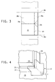
- the adhesive layer 16 is an elastic, conformable and flexible adhesive. Suitable adhesives include materials conventionally used in the waterproofing art, such as rubber-modified asphaltic or butyl adhesive.
- the adhesive layer 16 extends an equivalent amount as the top sheet 14 when exposed to an equivalent level of stress.
- the average thickness of the adhesive layer 16 can be 5-100 mils (i.e. 0,127-2,54 mm).
- the minimum thickness of the adhesive layer 16 depends on what is needed to provide good adhesion and, optionally, if desired, nail sealability given the adhesive composition used. For instance, a 10-60 mils (i.e. 0,254-1,524 mm) thick layer of butyl adhesive has been found to be sufficient.
- the release sheet 18 can be any known material suitable for use as a release liner on rubberized asphalt and butyl adhesive.
- FIG. 3 illustrates the pattern of perforations in the release sheet 18.
- perforations 18e extending in the cross direction divide the release sheet 18 into two roughly equal major portions along the machine direction and perforations 18f extending in the machine direction divide the release sheet 18 into two unequal portions along the cross direction, a narrower edge portion 18a and a wider bulk portion 18b.
- a plurality of corner flashing members 10 can be formed from an elongated strip of flashing material 12.
- a cut line 18d represents where a cut is made in the flashing material 12 in order to divide the elongated strip of the flashing material 12 into individual sections of the flashing material 12 each forming a single corner flashing member 10.
- a triangular portion 18c of the release sheet 18 is removed from the flashing material 12, thereby exposing a triangular portion 18c of the underlying adhesive layer 16.
- the triangle is defined by the perforations in the release sheet 18 and the edge of the strip of flashing material 12.
- the tip of the triangle is located at the intersection of the machine direction perforation 18f and the cross direction perforation 18e, where the triangle has a 90° angle, and the base of the triangle is the edge of the strip where the triangle has two 45° angles.
- the triangular portion 18c is bisected by the cross direction perforation 18e.
- the triangular portion 18c of the release sheet 18 can be perforated for removal at the building site; alternatively the triangular portion 18c can be scored and removed using a knife or box cutter.
- the strip of flashing material 12 is folded along the cross direction perforation 18e, thereby attaching the exposed adhesive layers 16 on opposite sides of the fold line such that the exposed adhesive layers 16 make continuous contact.
- the resulting adhesive-to-adhesive layer effectively becomes one continuous adhesive layer with no space between the original adhesive layers 16. This provides no seam or hole for water to infiltrate.
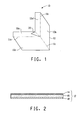
- the resulting adhesive-to-adhesive layer forms a strong, durable dog-eared seal 20 as shown in Fig. 1 .
- the corner flashing member 10 is depicted in a right hand corner, however the flashing material 12 can be folded such that the corner flashing member 10 fits into either a right hand corner or a left hand corner.
- the flashing material 12 is folded along the cross direction perforation 18e in the direction opposite the direction it was folded to form the seal 20, to form a right angle between topsheet surfaces.
- the flashing material 12 is also folded along the machine direction perforation 18f to form a right angle between topsheet surfaces, such that the corner-shaped flashing member 10 is formed.
- the method for forming the flashing member 10 can be carried out at the time of installation starting with a strip of flashing material 12.
- the corner members 10 can be preformed and delivered to the building site for subsequent installation.
- a length of flashing material 12 having the above described pattern of perforations in the release sheet 18 is formed and the triangular portions 18c of the release sheet 18 are removed to expose the underlying butyl adhesive.
- the length of flashing material 12 is then folded in a "fanfold" manner such that the material is folded in alternating directions at each cross direction perforation 18e, and such that the exposed butyl adhesive is folded on itself to form the seal 20.
- the thus folded material can be packaged for delivery to installation sites.
- the installer can complete the formation of the corner member 10 just prior to installation, by cutting along perforation 18d to form individual corner flashing members 10 which are folded onto themselves, and subsequently inverting or turning the corner "inside out” to form the shape of a right angle corner for installation.
- the release sheet 18 is removed from the outer surfaces of the flashing member 10 to expose the adhesive layer 16 on the outer surfaces.
- the exposed adhesive can then be attached directly to the interior surfaces of the recessed window, thereby affixing the flashing member 10 an installation position, as illustrated in Fig. 4 .
- preferably only one piece of the release sheet 18 is removed at a time, so that the corner flashing member 10 can be first affixed to the framing members 22 forming the window opening.
- the flashing material 12 can also be extended and wrapped around the corner of the recessed sill 24 and window jamb surfaces 26 to cover a portion of the exterior wall 28.
- fasteners F such as nails or staples are installed through the flashing material 12 to secure it to the exterior wall 28.
- the flashing material 12 on the exterior wall 28 extends at least 2 inches (i.e. 50,8 mm) from the recessed sill 24 and jamb 26 surfaces of the recessed window opening.
- the seal 20 extends outward in a dog-eared manner, but for convenience purposes can be attached to surface 10a (or 10a') as shown in Fig. 4 .
Landscapes
- Engineering & Computer Science (AREA)
- Civil Engineering (AREA)
- Structural Engineering (AREA)
- Adhesive Tapes (AREA)
- Building Environments (AREA)
- Laminated Bodies (AREA)
Claims (4)
- Verfahren zum Abdecken zurückgesetzter Ecken in einem Gebäude, wobei das Verfahren aufweist:Bereitstellen eines Streifens aus Abdeckmaterial (12) mit einer elastischen, schmiegsamen, flexiblen, wasserfesten Deckschicht (14), einer Kontaktklebstoffschicht (16), die eine Oberfläche der Deckschicht (14) bedeckt, und einer Trennfolie (18), die lösbar an der Klebstoffschicht (16) befestigt ist, und eine Perforation (18e) in Querrichtung, welche die Trennfolie (18) in zwei Hauptabschnitte unterteilt, und eine Perforation (18f) in Maschinenrichtung aufweist, welche die Trennfolie (18) in einen Randabschnitt (18a) und einen Hauptabschnitt (18b) unterteilt,gekennzeichnet durchEntfernen eines dreieckigen Abschnitts (18c) der Trennfolie (18), wobei der dreieckige Abschnitt (18c) die Form eines gleichschenkligen Dreiecks hat, das durch die Perforation (18e) in Querrichtung der Trennfolie (18) halbiert wird, wobei das Dreieck am Schnittpunkt der Perforation (18f) in Maschinenrichtung und der Perforation (18e) in Querrichtung einen Winkel von 90° und entlang der Kante des Randabschnitts (18a) der Trennfolie (18) zwei Winkel von 45° aufweist, wodurch ein dreieckiger Abschnitt (18c) der Klebstoffschicht (16) freigelegt wird;Falten des Abdeckmaterials (12) entlang der Perforation (18e) in Querrichtung, wodurch die freigelegten Klebstoffschichten (16) an gegenüberliegenden Seiten der Faltlinie so fixiert werden, daß die freigelegten Klebstoffschichten (16) in dauernden Kontakt miteinander kommen;Falten des Abdeckmaterials (12) entlang der Perforation (18e) in Querrichtung, um einen rechten Winkel zwischen den Deckschichtoberflächen (14) zu bilden, und Falten des Abdeckmaterials (12) entlang der Perforation (18f) in Maschinenrichtung, um einen rechten Winkel zwischen den Deckschichtoberflächen (14) zu bilden und dadurch das eckförmige Abdeckelement (10) zu formen;Entfernen der übrigen Trennfolie (18) von dem eckförmigen Abdeckelement (10), um die übrige Klebstoffschicht (16) freizulegen; undBefestigen der freigelegten übrigen Klebstoffschicht (16) an den Oberflächen der zurückgesetzten Ecke, wodurch das eckförmige Abdeckelement (10) in einer Installationsposition fixiert wird,wobei die Deckschicht (14) und die Kontaktklebstoffschicht (16) bei einer angreifenden Spannung von nicht mehr als 10 N/cm eine Dehnung von mindestens etwa 150% aufweisen.
- Verfahren nach Anspruch 1, wobei der Klebstoff (16) ein gummierter Asphalt-oder Butylklebstoff ist.
- Verfahren nach Anspruch 1, wobei die Deckschicht (14) ein kontinuierlicher Film, ein Gewebe, ein Faservlies oder ein Laminat daraus ist.
- Abdeckelement (10) zum Abdecken zurückgesetzter Ecken in einem Gebäude, mit einer elastischen, schmiegsamen, flexiblen, wasserfesten Deckschicht (14), wobei eine Kontaktklebstoffschicht (16) die eine Oberfläche der Deckschicht (14) bedeckt, und eine Trennfolie (18) lösbar an der Klebstoffschicht (16) befestigt ist,
wobei zum Festhalten des Abdeckelements (10) innerhalb der zurückgesetzten Ecke keine Befestigungselemente (F) erforderlich sind,
dadurch gekennzeichnet, daß
die Deckschicht (14) und die Kontaktklebstoffschicht (16) bei einer angreifenden Spannung von nicht mehr als 10 N/cm eine Dehnung von mindestens etwa 150% aufweisen, und
die Kontaktklebstoffschicht (16) aufweist: eine Perforation (18e) in Querrichtung, welche die Trennfolie (18) in zwei Hauptabschnitte unterteilt, und eine Perforation (18f) in Maschinenrichtung, welche die Trennfolie (18) in einen Wandabschnitt (18a) und einen Hauptabschnitt (18b) unterteilt, und einen dreieckigen Abschnitt (18c) in Form eines gleichschenkligen Dreiecks, das durch die Perforation (18e) in Querrichtung der Trennfolie (18) halbiert wird, wobei das Dreieck am Schnittpunkt der Perforation (18f) in Maschinenrichtung und der Perforation (18e) in Querrichtung einen Winkel von 90° und entlang der Kante des Randabschnitts (18a) der Trennfolie (18) zwei Winkel von 45° aufweist, wodurch ein dreieckiger Abschnitt (18c) der Klebstoffschicht (16) freigelegt wird.
Applications Claiming Priority (2)
| Application Number | Priority Date | Filing Date | Title |
|---|---|---|---|
| US11/906,707 US20090090068A1 (en) | 2007-10-03 | 2007-10-03 | Self-adhesive corner flashing member and method for making and using |
| PCT/US2008/078644 WO2009046233A1 (en) | 2007-10-03 | 2008-10-03 | Self adhesive extensible and foldable corner flashing material for buildings |
Publications (2)
| Publication Number | Publication Date |
|---|---|
| EP2193249A1 EP2193249A1 (de) | 2010-06-09 |
| EP2193249B1 true EP2193249B1 (de) | 2011-02-16 |
Family
ID=40193400
Family Applications (1)
| Application Number | Title | Priority Date | Filing Date |
|---|---|---|---|
| EP08836676A Not-in-force EP2193249B1 (de) | 2007-10-03 | 2008-10-03 | Selbsthaftende, dehn- und faltbare Eckabdeckung für Gebäude |
Country Status (7)
| Country | Link |
|---|---|
| US (1) | US20090090068A1 (de) |
| EP (1) | EP2193249B1 (de) |
| JP (1) | JP2010540810A (de) |
| CN (1) | CN101815838B (de) |
| AT (1) | ATE498757T1 (de) |
| DE (1) | DE602008005041D1 (de) |
| WO (1) | WO2009046233A1 (de) |
Families Citing this family (19)
| Publication number | Priority date | Publication date | Assignee | Title |
|---|---|---|---|---|
| US9068354B2 (en) * | 2009-01-09 | 2015-06-30 | Building Materials Investment Corporation | Corner patches and methods for TPO roofing |
| US8161688B2 (en) * | 2009-01-09 | 2012-04-24 | Building Materials Investment Corp. | Outside corner patch for TPO roofing |
| CN102785452A (zh) * | 2011-05-20 | 2012-11-21 | 德州东方土工材料股份有限公司 | 宽幅自粘高分子复合防水卷材一次成型生产线 |
| US8850775B2 (en) * | 2012-05-04 | 2014-10-07 | Garland Industries, Inc. | Non-welded coping caps and transitions |
| US9133621B2 (en) | 2012-12-18 | 2015-09-15 | Building Materials Investment Corporation | Self adhesive universal inside corner patch for membrane roofing |
| US9151039B2 (en) * | 2013-02-06 | 2015-10-06 | Mortar Net Usa, Ltd. | Adjustable drip edge corner |
| US9163450B2 (en) | 2013-08-13 | 2015-10-20 | Gary William Messenger | Method for flashing a window or door opening |
| AU2015201723B2 (en) * | 2014-04-06 | 2019-12-05 | Heinz Tkatschenko | Flashing assembly and flashing junction cover assembly |
| US20160145857A1 (en) * | 2014-11-26 | 2016-05-26 | Dale A. Dreyer | Elastomeric flashing assembly and method for same |
| US9951514B2 (en) * | 2015-09-17 | 2018-04-24 | Todd DeBuff | Flashing for concrete board siding |
| US9745791B1 (en) * | 2016-04-25 | 2017-08-29 | Top Industrial, Inc. | Corner flashing insert for recessed windows |
| US10954669B2 (en) * | 2018-03-12 | 2021-03-23 | Scott W. Sander | Method and apparatus for sealing grout space |
| US11549256B2 (en) | 2018-03-12 | 2023-01-10 | Scott W. Sander | Method and apparatus for sealing grout space |
| US10844603B2 (en) * | 2018-10-30 | 2020-11-24 | Pro Fastening Systems, Inc. | Roof deck assembly and method |
| CH715676A1 (de) * | 2018-12-20 | 2020-06-30 | Hafner Ag Gewerbehaus | Dichtelement für einen Wand- und Bodenanschluss von sanitären Artikeln. |
| US11136768B2 (en) * | 2020-02-12 | 2021-10-05 | Steven Joseph Brown | Inside corner drywall finishing |
| CA3146527A1 (en) * | 2021-01-19 | 2022-07-19 | Gabe Coscarella | Flashing for a building opening |
| DE202021104208U1 (de) * | 2021-08-05 | 2021-09-09 | Thomas Seidl | Abdichtelement |
| AT525167B1 (de) | 2022-03-25 | 2023-01-15 | Burghart Michael | Klebeecke |
Family Cites Families (15)
| Publication number | Priority date | Publication date | Assignee | Title |
|---|---|---|---|---|
| JPS53144217U (de) * | 1977-04-19 | 1978-11-14 | ||
| US4700512A (en) * | 1986-07-21 | 1987-10-20 | Laska Walter A | Corner flashing membrane |
| US5077943A (en) * | 1990-07-19 | 1992-01-07 | Mcgady Donald L | Corner flashing |
| US5916654A (en) * | 1997-08-27 | 1999-06-29 | Phillips; Aaron R. | Method and apparatus for preventing adhesion of multi-part release liners |
| DK173494B1 (da) * | 1997-11-10 | 2001-01-02 | Velux Ind As | Sæt af elementer og fremgangsmåde ved brug af sættet til inddækning af et taggennembrydende element |
| WO2001071142A1 (en) * | 2000-03-22 | 2001-09-27 | Exterior Research And Design, L.L.C. | Window seal construction |
| WO2001081689A2 (en) * | 2000-04-25 | 2001-11-01 | E.I. Dupont De Nemours And Company | Stretchable flashing materials and processes for making |
| US7735291B2 (en) * | 2000-10-27 | 2010-06-15 | Gene Summy | Corner flashing system |
| US6401402B1 (en) * | 2001-02-07 | 2002-06-11 | Mark F. Williams | Pre-folded flashing systems and method |
| JP2004244832A (ja) * | 2003-02-12 | 2004-09-02 | Asahi Rubber Kk | 建築用防水シートおよび該建築用防水シートを用いたサッシ枠の取付方法 |
| JP4138717B2 (ja) * | 2004-08-31 | 2008-08-27 | 日東電工株式会社 | 展延性を有する防水気密用粘着シートによる3面交差構造物の防水施工方法 |
| US8399088B2 (en) * | 2004-10-15 | 2013-03-19 | E I Du Pont De Nemours And Company | Self-adhering flashing system having high extensibility and low retraction |
| US20060101726A1 (en) * | 2004-11-16 | 2006-05-18 | Pacc Systems I.P., Llc | Sill pan flashing for doors and windows |
| US20060137262A1 (en) * | 2004-12-14 | 2006-06-29 | Crowder-Moore Barbara J | Self-adhered flange for use with non-flanged windows |
| US7641952B2 (en) * | 2006-02-21 | 2010-01-05 | E.I. Du Pont De Nemours And Company | Durable metallized self-adhesive laminates |
-
2007
- 2007-10-03 US US11/906,707 patent/US20090090068A1/en not_active Abandoned
-
2008
- 2008-10-03 CN CN200880109948.3A patent/CN101815838B/zh not_active Expired - Fee Related
- 2008-10-03 EP EP08836676A patent/EP2193249B1/de not_active Not-in-force
- 2008-10-03 JP JP2010528143A patent/JP2010540810A/ja active Pending
- 2008-10-03 AT AT08836676T patent/ATE498757T1/de not_active IP Right Cessation
- 2008-10-03 WO PCT/US2008/078644 patent/WO2009046233A1/en active Application Filing
- 2008-10-03 DE DE602008005041T patent/DE602008005041D1/de active Active
Also Published As
| Publication number | Publication date |
|---|---|
| US20090090068A1 (en) | 2009-04-09 |
| ATE498757T1 (de) | 2011-03-15 |
| DE602008005041D1 (de) | 2011-03-31 |
| CN101815838B (zh) | 2012-12-12 |
| WO2009046233A1 (en) | 2009-04-09 |
| JP2010540810A (ja) | 2010-12-24 |
| EP2193249A1 (de) | 2010-06-09 |
| CN101815838A (zh) | 2010-08-25 |
Similar Documents
| Publication | Publication Date | Title |
|---|---|---|
| EP2193249B1 (de) | Selbsthaftende, dehn- und faltbare Eckabdeckung für Gebäude | |
| US7867591B2 (en) | Assembly tape with perforation and expansion reserve | |
| US9163450B2 (en) | Method for flashing a window or door opening | |
| EP1825092A2 (de) | Selbsthaftender flansch zur verwendung mit nichtgeflanschten fenstern | |
| US10267036B2 (en) | Universal joint sealing tape for different profile dimensions and seal arrangement having such a joint sealing tape | |
| US7201820B2 (en) | Flexible flashing for multiplanar building surfaces | |
| US7735291B2 (en) | Corner flashing system | |
| US20110214384A1 (en) | Flashing for Integrating Windows with Weather Resistant Barrier | |
| US20070193126A1 (en) | Apparatus and method for door and window side flashing | |
| US9745791B1 (en) | Corner flashing insert for recessed windows | |
| DE19948058B4 (de) | Dampfbremsen-Klebeband für eine Firstpfette und dessen Verwendung | |
| US7445828B2 (en) | Assembly tape with sectional protective film | |
| CA2477660C (en) | Assembly tape with slits and folds | |
| PL216500B1 (pl) | Taśma uszczelniająco-izolująca stosowana jako uszczelnienie i izolacja szczeliny pomiędzy ramą okienną lub drzwiową a murem | |
| US9745790B2 (en) | Prefabricated flashing product | |
| US6103356A (en) | Nonadhesive laminate for structural sealing | |
| US20050055914A1 (en) | Corner guard | |
| US9745789B2 (en) | Prefabricated flashing product | |
| HU224894B1 (en) | Substrate for sound isolation of floating floors | |
| US20150147534A1 (en) | Structural batten | |
| US20050249908A1 (en) | Vapor retarding film and folding thereof | |
| US20240167278A1 (en) | Bendable structural sheathing | |
| EP2547834B1 (de) | Luftspaltbarriere | |
| JPH07259438A (ja) | 建築用防水テープ | |
| AU2019257523A1 (en) | An edge seal flashing |
Legal Events
| Date | Code | Title | Description |
|---|---|---|---|
| PUAI | Public reference made under article 153(3) epc to a published international application that has entered the european phase |
Free format text: ORIGINAL CODE: 0009012 |
|
| 17P | Request for examination filed |
Effective date: 20100303 |
|
| AK | Designated contracting states |
Kind code of ref document: A1 Designated state(s): AT BE BG CH CY CZ DE DK EE ES FI FR GB GR HR HU IE IS IT LI LT LU LV MC MT NL NO PL PT RO SE SI SK TR |
|
| AX | Request for extension of the european patent |
Extension state: AL BA MK RS |
|
| GRAP | Despatch of communication of intention to grant a patent |
Free format text: ORIGINAL CODE: EPIDOSNIGR1 |
|
| RTI1 | Title (correction) |
Free format text: SELF-ADHESIVE EXTENSIBLE AND FOLDABLE CORNER FLASHING FOR BUILDINGS |
|
| DAX | Request for extension of the european patent (deleted) | ||
| GRAS | Grant fee paid |
Free format text: ORIGINAL CODE: EPIDOSNIGR3 |
|
| GRAA | (expected) grant |
Free format text: ORIGINAL CODE: 0009210 |
|
| AK | Designated contracting states |
Kind code of ref document: B1 Designated state(s): AT BE BG CH CY CZ DE DK EE ES FI FR GB GR HR HU IE IS IT LI LT LU LV MC MT NL NO PL PT RO SE SI SK TR |
|
| REG | Reference to a national code |
Ref country code: GB Ref legal event code: FG4D |
|
| REG | Reference to a national code |
Ref country code: CH Ref legal event code: EP |
|
| REG | Reference to a national code |
Ref country code: IE Ref legal event code: FG4D |
|
| REF | Corresponds to: |
Ref document number: 602008005041 Country of ref document: DE Date of ref document: 20110331 Kind code of ref document: P |
|
| REG | Reference to a national code |
Ref country code: DE Ref legal event code: R096 Ref document number: 602008005041 Country of ref document: DE Effective date: 20110331 |
|
| REG | Reference to a national code |
Ref country code: NL Ref legal event code: VDEP Effective date: 20110216 |
|
| LTIE | Lt: invalidation of european patent or patent extension |
Effective date: 20110216 |
|
| PG25 | Lapsed in a contracting state [announced via postgrant information from national office to epo] |
Ref country code: SE Free format text: LAPSE BECAUSE OF FAILURE TO SUBMIT A TRANSLATION OF THE DESCRIPTION OR TO PAY THE FEE WITHIN THE PRESCRIBED TIME-LIMIT Effective date: 20110216 Ref country code: PT Free format text: LAPSE BECAUSE OF FAILURE TO SUBMIT A TRANSLATION OF THE DESCRIPTION OR TO PAY THE FEE WITHIN THE PRESCRIBED TIME-LIMIT Effective date: 20110616 Ref country code: HR Free format text: LAPSE BECAUSE OF FAILURE TO SUBMIT A TRANSLATION OF THE DESCRIPTION OR TO PAY THE FEE WITHIN THE PRESCRIBED TIME-LIMIT Effective date: 20110216 Ref country code: GR Free format text: LAPSE BECAUSE OF FAILURE TO SUBMIT A TRANSLATION OF THE DESCRIPTION OR TO PAY THE FEE WITHIN THE PRESCRIBED TIME-LIMIT Effective date: 20110517 Ref country code: NO Free format text: LAPSE BECAUSE OF FAILURE TO SUBMIT A TRANSLATION OF THE DESCRIPTION OR TO PAY THE FEE WITHIN THE PRESCRIBED TIME-LIMIT Effective date: 20110516 Ref country code: LV Free format text: LAPSE BECAUSE OF FAILURE TO SUBMIT A TRANSLATION OF THE DESCRIPTION OR TO PAY THE FEE WITHIN THE PRESCRIBED TIME-LIMIT Effective date: 20110216 Ref country code: LT Free format text: LAPSE BECAUSE OF FAILURE TO SUBMIT A TRANSLATION OF THE DESCRIPTION OR TO PAY THE FEE WITHIN THE PRESCRIBED TIME-LIMIT Effective date: 20110216 Ref country code: ES Free format text: LAPSE BECAUSE OF FAILURE TO SUBMIT A TRANSLATION OF THE DESCRIPTION OR TO PAY THE FEE WITHIN THE PRESCRIBED TIME-LIMIT Effective date: 20110527 |
|
| PG25 | Lapsed in a contracting state [announced via postgrant information from national office to epo] |
Ref country code: AT Free format text: LAPSE BECAUSE OF FAILURE TO SUBMIT A TRANSLATION OF THE DESCRIPTION OR TO PAY THE FEE WITHIN THE PRESCRIBED TIME-LIMIT Effective date: 20110216 Ref country code: PL Free format text: LAPSE BECAUSE OF FAILURE TO SUBMIT A TRANSLATION OF THE DESCRIPTION OR TO PAY THE FEE WITHIN THE PRESCRIBED TIME-LIMIT Effective date: 20110216 Ref country code: FI Free format text: LAPSE BECAUSE OF FAILURE TO SUBMIT A TRANSLATION OF THE DESCRIPTION OR TO PAY THE FEE WITHIN THE PRESCRIBED TIME-LIMIT Effective date: 20110216 Ref country code: SI Free format text: LAPSE BECAUSE OF FAILURE TO SUBMIT A TRANSLATION OF THE DESCRIPTION OR TO PAY THE FEE WITHIN THE PRESCRIBED TIME-LIMIT Effective date: 20110216 Ref country code: NL Free format text: LAPSE BECAUSE OF FAILURE TO SUBMIT A TRANSLATION OF THE DESCRIPTION OR TO PAY THE FEE WITHIN THE PRESCRIBED TIME-LIMIT Effective date: 20110216 Ref country code: BE Free format text: LAPSE BECAUSE OF FAILURE TO SUBMIT A TRANSLATION OF THE DESCRIPTION OR TO PAY THE FEE WITHIN THE PRESCRIBED TIME-LIMIT Effective date: 20110216 Ref country code: CY Free format text: LAPSE BECAUSE OF FAILURE TO SUBMIT A TRANSLATION OF THE DESCRIPTION OR TO PAY THE FEE WITHIN THE PRESCRIBED TIME-LIMIT Effective date: 20110216 Ref country code: BG Free format text: LAPSE BECAUSE OF FAILURE TO SUBMIT A TRANSLATION OF THE DESCRIPTION OR TO PAY THE FEE WITHIN THE PRESCRIBED TIME-LIMIT Effective date: 20110516 |
|
| PG25 | Lapsed in a contracting state [announced via postgrant information from national office to epo] |
Ref country code: EE Free format text: LAPSE BECAUSE OF FAILURE TO SUBMIT A TRANSLATION OF THE DESCRIPTION OR TO PAY THE FEE WITHIN THE PRESCRIBED TIME-LIMIT Effective date: 20110216 Ref country code: DK Free format text: LAPSE BECAUSE OF FAILURE TO SUBMIT A TRANSLATION OF THE DESCRIPTION OR TO PAY THE FEE WITHIN THE PRESCRIBED TIME-LIMIT Effective date: 20110216 |
|
| PG25 | Lapsed in a contracting state [announced via postgrant information from national office to epo] |
Ref country code: SK Free format text: LAPSE BECAUSE OF FAILURE TO SUBMIT A TRANSLATION OF THE DESCRIPTION OR TO PAY THE FEE WITHIN THE PRESCRIBED TIME-LIMIT Effective date: 20110216 Ref country code: CZ Free format text: LAPSE BECAUSE OF FAILURE TO SUBMIT A TRANSLATION OF THE DESCRIPTION OR TO PAY THE FEE WITHIN THE PRESCRIBED TIME-LIMIT Effective date: 20110216 Ref country code: RO Free format text: LAPSE BECAUSE OF FAILURE TO SUBMIT A TRANSLATION OF THE DESCRIPTION OR TO PAY THE FEE WITHIN THE PRESCRIBED TIME-LIMIT Effective date: 20110216 |
|
| PLBE | No opposition filed within time limit |
Free format text: ORIGINAL CODE: 0009261 |
|
| STAA | Information on the status of an ep patent application or granted ep patent |
Free format text: STATUS: NO OPPOSITION FILED WITHIN TIME LIMIT |
|
| 26N | No opposition filed |
Effective date: 20111117 |
|
| REG | Reference to a national code |
Ref country code: DE Ref legal event code: R097 Ref document number: 602008005041 Country of ref document: DE Effective date: 20111117 |
|
| PG25 | Lapsed in a contracting state [announced via postgrant information from national office to epo] |
Ref country code: IT Free format text: LAPSE BECAUSE OF FAILURE TO SUBMIT A TRANSLATION OF THE DESCRIPTION OR TO PAY THE FEE WITHIN THE PRESCRIBED TIME-LIMIT Effective date: 20110216 Ref country code: MC Free format text: LAPSE BECAUSE OF NON-PAYMENT OF DUE FEES Effective date: 20111031 |
|
| REG | Reference to a national code |
Ref country code: IE Ref legal event code: MM4A |
|
| PG25 | Lapsed in a contracting state [announced via postgrant information from national office to epo] |
Ref country code: IE Free format text: LAPSE BECAUSE OF NON-PAYMENT OF DUE FEES Effective date: 20111003 |
|
| PGFP | Annual fee paid to national office [announced via postgrant information from national office to epo] |
Ref country code: DE Payment date: 20120927 Year of fee payment: 5 Ref country code: FR Payment date: 20121018 Year of fee payment: 5 |
|
| PG25 | Lapsed in a contracting state [announced via postgrant information from national office to epo] |
Ref country code: MT Free format text: LAPSE BECAUSE OF FAILURE TO SUBMIT A TRANSLATION OF THE DESCRIPTION OR TO PAY THE FEE WITHIN THE PRESCRIBED TIME-LIMIT Effective date: 20110216 |
|
| PGFP | Annual fee paid to national office [announced via postgrant information from national office to epo] |
Ref country code: GB Payment date: 20121003 Year of fee payment: 5 |
|
| PG25 | Lapsed in a contracting state [announced via postgrant information from national office to epo] |
Ref country code: LU Free format text: LAPSE BECAUSE OF NON-PAYMENT OF DUE FEES Effective date: 20111003 |
|
| REG | Reference to a national code |
Ref country code: CH Ref legal event code: PL |
|
| PG25 | Lapsed in a contracting state [announced via postgrant information from national office to epo] |
Ref country code: CH Free format text: LAPSE BECAUSE OF NON-PAYMENT OF DUE FEES Effective date: 20121031 Ref country code: IS Free format text: LAPSE BECAUSE OF FAILURE TO SUBMIT A TRANSLATION OF THE DESCRIPTION OR TO PAY THE FEE WITHIN THE PRESCRIBED TIME-LIMIT Effective date: 20110216 Ref country code: LI Free format text: LAPSE BECAUSE OF NON-PAYMENT OF DUE FEES Effective date: 20121031 |
|
| PG25 | Lapsed in a contracting state [announced via postgrant information from national office to epo] |
Ref country code: TR Free format text: LAPSE BECAUSE OF FAILURE TO SUBMIT A TRANSLATION OF THE DESCRIPTION OR TO PAY THE FEE WITHIN THE PRESCRIBED TIME-LIMIT Effective date: 20110216 |
|
| PG25 | Lapsed in a contracting state [announced via postgrant information from national office to epo] |
Ref country code: HU Free format text: LAPSE BECAUSE OF FAILURE TO SUBMIT A TRANSLATION OF THE DESCRIPTION OR TO PAY THE FEE WITHIN THE PRESCRIBED TIME-LIMIT Effective date: 20110216 |
|
| GBPC | Gb: european patent ceased through non-payment of renewal fee |
Effective date: 20131003 |
|
| PG25 | Lapsed in a contracting state [announced via postgrant information from national office to epo] |
Ref country code: GB Free format text: LAPSE BECAUSE OF NON-PAYMENT OF DUE FEES Effective date: 20131003 |
|
| REG | Reference to a national code |
Ref country code: FR Ref legal event code: ST Effective date: 20140630 |
|
| REG | Reference to a national code |
Ref country code: DE Ref legal event code: R119 Ref document number: 602008005041 Country of ref document: DE Effective date: 20140501 |
|
| PG25 | Lapsed in a contracting state [announced via postgrant information from national office to epo] |
Ref country code: DE Free format text: LAPSE BECAUSE OF NON-PAYMENT OF DUE FEES Effective date: 20140501 Ref country code: FR Free format text: LAPSE BECAUSE OF NON-PAYMENT OF DUE FEES Effective date: 20131031 |