EP2192829B1 - Barre centrale pour pulvérisation et/ou distribution de produits sous forme de préparations en poudre, liquides, et en granulés - Google Patents
Barre centrale pour pulvérisation et/ou distribution de produits sous forme de préparations en poudre, liquides, et en granulés Download PDFInfo
- Publication number
- EP2192829B1 EP2192829B1 EP08783137.6A EP08783137A EP2192829B1 EP 2192829 B1 EP2192829 B1 EP 2192829B1 EP 08783137 A EP08783137 A EP 08783137A EP 2192829 B1 EP2192829 B1 EP 2192829B1
- Authority
- EP
- European Patent Office
- Prior art keywords
- spraying
- central bar
- powder
- bar
- liquid
- Prior art date
- Legal status (The legal status is an assumption and is not a legal conclusion. Google has not performed a legal analysis and makes no representation as to the accuracy of the status listed.)
- Active
Links
Images


Classifications
-
- A—HUMAN NECESSITIES
- A01—AGRICULTURE; FORESTRY; ANIMAL HUSBANDRY; HUNTING; TRAPPING; FISHING
- A01C—PLANTING; SOWING; FERTILISING
- A01C15/00—Fertiliser distributors
- A01C15/005—Undercarriages, tanks, hoppers, stirrers specially adapted for seeders or fertiliser distributors
-
- A—HUMAN NECESSITIES
- A01—AGRICULTURE; FORESTRY; ANIMAL HUSBANDRY; HUNTING; TRAPPING; FISHING
- A01C—PLANTING; SOWING; FERTILISING
- A01C23/00—Distributing devices specially adapted for liquid manure or other fertilising liquid, including ammonia, e.g. transport tanks or sprinkling wagons
- A01C23/008—Tanks, chassis or related parts
-
- A—HUMAN NECESSITIES
- A01—AGRICULTURE; FORESTRY; ANIMAL HUSBANDRY; HUNTING; TRAPPING; FISHING
- A01M—CATCHING, TRAPPING OR SCARING OF ANIMALS; APPARATUS FOR THE DESTRUCTION OF NOXIOUS ANIMALS OR NOXIOUS PLANTS
- A01M7/00—Special adaptations or arrangements of liquid-spraying apparatus for purposes covered by this subclass
- A01M7/0003—Atomisers or mist blowers
- A01M7/0014—Field atomisers, e.g. orchard atomisers, self-propelled, drawn or tractor-mounted
-
- A—HUMAN NECESSITIES
- A01—AGRICULTURE; FORESTRY; ANIMAL HUSBANDRY; HUNTING; TRAPPING; FISHING
- A01M—CATCHING, TRAPPING OR SCARING OF ANIMALS; APPARATUS FOR THE DESTRUCTION OF NOXIOUS ANIMALS OR NOXIOUS PLANTS
- A01M7/00—Special adaptations or arrangements of liquid-spraying apparatus for purposes covered by this subclass
- A01M7/005—Special arrangements or adaptations of the spraying or distributing parts, e.g. adaptations or mounting of the spray booms, mounting of the nozzles, protection shields
- A01M7/0053—Mounting of the spraybooms
-
- A—HUMAN NECESSITIES
- A01—AGRICULTURE; FORESTRY; ANIMAL HUSBANDRY; HUNTING; TRAPPING; FISHING
- A01M—CATCHING, TRAPPING OR SCARING OF ANIMALS; APPARATUS FOR THE DESTRUCTION OF NOXIOUS ANIMALS OR NOXIOUS PLANTS
- A01M7/00—Special adaptations or arrangements of liquid-spraying apparatus for purposes covered by this subclass
- A01M7/005—Special arrangements or adaptations of the spraying or distributing parts, e.g. adaptations or mounting of the spray booms, mounting of the nozzles, protection shields
- A01M7/0071—Construction of the spray booms
Definitions
- the invention disclosed in this specification pertains, in a general way, to the technological field of agricultural machinery and implements, and refers more specifically, to a central bar for spraying and/or distributing products in powder, liquid and granulate formulations, with a hitherto unknown placement of its components, since it is fixed between the front wheel and the back wheel of the propeller vehicle, which associated to the application -in an innovative way- of a series of technological resources in the central frame as regards the propeller vehicle, creates from part of the central frame a set of two brackets fixed on the propeller vehicle chassis, this part being a component of a horizontal pantograph set and two vertical pantograph sets, the vertical ones having an axis which joins the upper side arms thereof in a rigid way.
- the central frame is also composed of actuating and pulling elements articulated by means of balls and cross pieces, supplementing in this way the opening and closing features of the side bars, the work height rigging of the whole central bar, independent opening and closing of the side bars and an angular movement in the vertical direction, synchronized or independent from the same.
- the state of the art in this technological field consists of spraying bars for agricultural sprayers and fertilizer applicators, agricultural enhancers in powder, liquid or granulate forms. All the spraying and distribution bars comprised within the state of the art use the same mechanic or hydraulic principles and possess equivalent constructive formulas which produce similar results.
- the impact and vibration absorbing means in said conventional equipment are composed of mechanisms which have flaws in damping and stabilization during the work, which are made worse by the fact that the existing frame systems are not independent from the vehicle's movements as regards the bars, transferring to the application systems strong impacts which may cause the appearance of cracks in the relevant mechanisms.
- Document EP 1 525 784 describes a central bar for spraying products including a central frame set provided with a horizontal pantograph subset.
- the invention disclosed in this specification refers to spraying and distribution bars, with a new concept in placement, operativity and absorption of the vibrations and impacts inherent to the operation of this kind of equipment, featuring a series of advantages as regards the current state of the art.
- the proposed bar system is placed between the front and back wheels of the propeller vehicle, which may be placed beyond the axis of the wheels both to the front and the rear, and even thus the central position provides three major advantages as regards known placements, by promoting a better visualization of the bars during the application operations, apart from protecting the operator, since the spraying of chemicals takes place in front of the cabin and to the rear thereof, completely eliminating the possibility of the operator being reached.
- Another advantage inherent to this invention is the increase in the useful life of the central frame mechanisms and the application bars, due to their central placement, since when the propeller vehicle suffers any sudden oscillations -both lateral and vertical or a change in direction or system, through damping and stabilization items which are rubber bearings, accumulators, springs and hydraulic accumulators, it causes the effect of said load to be smaller, providing (as well as more durability) a better application of the products due to the great stability of the bars as regards the ground.
- tandem effect Another important effect which takes place when the bar is placed between the front and back wheels is the tandem effect, which reduces the vertical movement caused by the passage of one of the wheels over an uneven part of the ground, wherein one of the axes accompanies such uneven portion of the ground and the other one remains at ground level, since the movement of climbing or going down an obstacle is smaller at the intermediate point of the propeller vehicle, which significantly reduces the harmful effects caused by said oscillations and impacts.
- Another technical advantage of this new placement is the better side control the operator has in order to keep the spraying or distribution bar set aligned in the product application band, thus avoiding superposition or failures in the application.
- the invention comprises a novel set of balls and/or cross pieces in the components which make up the union between the side bars and/or the central frame, in order to enable movement of the side bars without losing horizontal and vertical alignment when the system movements take place simultaneously (in three dimensions), maintaining the uniform application of the products on the target.
- the central frame is designed in order to enable independence of the side bar movements as regards movements of the propeller vehicle, which is achieved through the joint action of a horizontal pantograph set which joins the side bars at their bottom bases, enabling vertical, simultaneous and reverse rotation of the side bars up to a limit of 20°, creating a state of balance between the same.
- the central bar may also have any of its side arms rotated, independently, through hydraulic actuators, in the vertical direction, with an angular movement of about 15° upwards and 5° downwards, rotated from components which are applied to the extensions of the top and bottom arms of the vertical pantographs, the horizontal pantograph also taking part in this, which creates a relative balance between the side bars which results in a counterweight system between them.
- the central bar In order to absorb shock, not only when braking but during ignition and changes of direction, the central bar has a set of articulated braces with balls and cross pieces, bearings and brackets, which keep a specific position of the side bars, but leave them in complete freedom for absorbing the horizontal oscillations caused by the propeller vehicle.
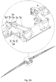
- the central bar (1) for spraying and/or distributing products in powder, liquid or granulate formulations, is composed of a central frame (3) to be fixed on a propeller vehicle associated to a set of side bars (4) which may or may not be divided in modules or sections (5).
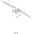
- FIG 2 it is possible to identify and understand the way in which said central bar (1) is fixed to the propeller vehicle (2).
- the central frame (3) of the central bar (1) is fixed on the chassis (2a) of the propeller vehicle (2), in an intermediate position between the front wheel (2b) and the back wheel (2c), in an attempt to minimize the effects of vibrations and jolts occurring when the equipment is at work; these enable the operator to visualize and control the alignment of said vehicle in the application bands, and prevent a fog of the applied product from being formed in front of the cabin thus decreasing the risk of the operator being intoxicated.
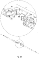
- Figure 3 shows the central frame (3) set and indicates its subsets: Brackets (3a), horizontal pantograph (3b), two vertical pantographs (3c), the subsets for vertical articulation of the bars (3d) and the opening, closing and shock absorbing subsets (3e), of the side bars (4).
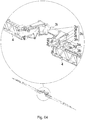
- FIG 4 shows, in perspective, the horizontal pantograph set (3b) in detail, and the two sets of vertical pantographs (3c), the horizontal one being composed by the following components: two bottom side arms (3h), the stabilizing bar (3g) and the brackets (3a), which when fixed to the chassis (2a), as indicated on Figure 2 , form a single rigid component.
- the horizontal pantograph (3b) interlinks the two side bars (4) and when it moves to the sides, it pulls the bases thereof towards sides opposite to their movement, thus causing a vertical rotation of the side bars (4), raising the end of one of them while lowering the end of the other one.
- Such placement of the parts creates a condition of balance of action-reaction forces between the side bars (4).
- the two vertical pantographs (3c) are formed and identified in this figure by the following components: Subset of brackets (3a); the two top side arms (3f) which form a rigid set with the axis (3i); the two bottom side arms (3h); and the braces (3j), forming a vertical pantograph (3c) for each side of the central frame (3), a hydraulic actuator (31) being also applied for each one, thus achieving the function of adjusting the working height of said central bar (1).
- the top subsets (3e), for opening and closing the side bars (4) are formed by the following pieces: bearing support (3m), fixed to the side bars (4), internal brace with a ball and a pin (3n), an attachment brace with a ball and a cross piece (3o), cross piece bracket (3p) and hydraulic actuator (3q), which set of components has the function of opening and closing and absorbing shocks in side bars (4) during movements when at work.
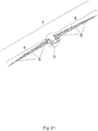
- Figure 7 shows the mentioned central bar (1), on a front view, simulating the vertical rotation movements of the side bars (4), in a condition of balance between them so as to absorb irregular movements caused by said propeller vehicle (2).
- constant tilting of said propeller vehicle (2) occurs, with the side bars (4) remaining inert to such movements and maintaining parallel quality of the ground.
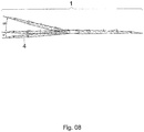
- Figure 8 on a front view, shows the central bar (1), with one of its side bars (4), rotated upwards in order to avoid obstacles, through the hydraulic actuator (3t) and the other one in the regular working position. Both side bars (4) may be driven by the hydraulic actuators (3t), independently or simultaneously, according to the needs during work.
Landscapes
- Life Sciences & Earth Sciences (AREA)
- Environmental Sciences (AREA)
- Engineering & Computer Science (AREA)
- Insects & Arthropods (AREA)
- Pest Control & Pesticides (AREA)
- Wood Science & Technology (AREA)
- Zoology (AREA)
- Soil Sciences (AREA)
- Water Supply & Treatment (AREA)
- Catching Or Destruction (AREA)
- Current-Collector Devices For Electrically Propelled Vehicles (AREA)
Claims (10)
- Barre centrale de pulvérisation et/ou distribution de produits sous forme de granulations en poudre, liquides et en granulés, dans laquelle la barre centrale (1) est composée d'un ensemble de châssis central (3) pourvu d'un sous-ensemble de pantographe horizontal (3b), qui réunit et maintient en équilibre de forces d'action-réaction deux barres latérales (4), caractérisée en ce que le sous-ensemble de pantographe horizontal (3b) réunit et maintient également en équilibre de forces d'action-réaction deux sous-ensembles de pantographe verticaux (3c), qui fonctionnent ensemble solidairement par l'intermédiaire d'un axe (3i).
- Barre centrale de pulvérisation et/ou distribution de produits sous forme de granulations en poudre, liquides et en granulés selon la revendication 1, dans laquelle l'ensemble de châssis central (3) est composé de deux sous-ensembles latéraux supérieurs (3e) et de deux sous-ensembles latéraux inférieurs (3d), qui sont formés à partir des extensions des bras latéraux supérieurs (3f) et des bras latéraux inférieurs (3h), dont tous pivotent au moyen de rotules et/de traverses, entraînant des mouvements tridimensionnels des barres latérales (4).
- Barre centrale de pulvérisation et/ou distribution de produits sous forme de granulations en poudre, liquides et en granulés selon la revendication 2, dans laquelle les sous-ensembles supérieurs (3e), destinés à ouvrir et fermer les barres latérales (4), sont formés par un bras de support (4), une entretoise interne munie d'une rotule et d'une goupille (3n), une entretoise de fixation munie d'une rotule et d'une traverse (3o), un bras de traverse (3p) et un actionneur hydraulique (3q).
- Barre centrale de pulvérisation et/ou distribution de produits sous forme de granulations en poudre, liquides et en granulés selon la revendication 2, dans laquelle les sous-ensembles inférieurs (3d) sont composés des éléments suivants : une extrémité de barre (3r) munie d'une traverse, une entretoise de fixation (3s), également munie d'une rotule et d'une traverse, et un actionneur hydraulique (3t), pour entraîner la rotation verticale indépendante pour chaque barre latérale (4), d'une telle barre centrale (1).
- Barre centrale de pulvérisation et/ou distribution de produits sous forme de granulations en poudre, liquides et en granulés selon la revendication 1, dans laquelle l'ensemble de pantographe horizontal (3b) est formé par les éléments suivants : des bras latéraux inférieurs (3h), une barre stabilisatrice (3g) et des bras (3e), qui, après avoir été fixés au châssis (2a), forment un seul composant rigide.
- Barre centrale de pulvérisation et/ou distribution de produits sous forme de granulations en poudre, liquides et en granulés selon la revendication 5, dans laquelle le pantographe horizontal (3b), par l'intermédiaire de sa barre stabilisatrice (3g), relie mutuellement les deux barres latérales (4) et, lorsqu'elles se déplacent sur le côté, tire les bases de celles-ci vers les côtés opposés de leur mouvement, en entraînant une rotation verticale des barres latérales (4), en levant l'extrémité de l'une d'elles tout en abaissant l'extrémité de l'autre.
- Barre centrale de pulvérisation et/ou distribution de produits sous forme de granulations en poudre, liquides et en granulés selon la revendication 1, dans laquelle les pantographes verticaux (3c) sont entraînés par des actionneurs hydrauliques (31) et sont formés par les éléments suivants : bras (3a), bras latéraux inférieurs (3h), entretoises (3j) et bras latéraux supérieurs (3f), qui forment un ensemble rigide avec l'axe (3i).
- Barre centrale de pulvérisation et/ou distribution de produits sous forme de granulations en poudre, liquides et en granulés selon la revendication 1, dans laquelle les paliers d'amortissement (3u), qui adoucissent les à-coups et les vibrations, sont supportés par les parois internes des bras de support (3m) contre les entretoises internes (3n), chaque palier travaillant vers chaque extrémité de l'entretoise.
- Barre centrale de pulvérisation et/ou distribution de produits sous forme de granulations en poudre, liquides et en granulés selon la revendication 1, dans laquelle les barres latérales (4) sont entraînées par des actionneurs hydrauliques (3t), de manière indépendante ou simultanée.
- Véhicule à propulsion (2) comportant une barre centrale selon l'une quelconque des revendications précédentes, dans lequel la barre centrale est placée dans une position intermédiaire entre les roues avant (2b) et arrière (2c) du véhicule (2).
Priority Applications (1)
| Application Number | Priority Date | Filing Date | Title |
|---|---|---|---|
| PL08783137T PL2192829T3 (pl) | 2007-09-28 | 2008-08-29 | Belka środkowa do rozpylania i/lub rozprowadzania produktów w proszku, preparatów płynnych i granulowanych |
Applications Claiming Priority (2)
| Application Number | Priority Date | Filing Date | Title |
|---|---|---|---|
| BRPI0703229A BRPI0703229B1 (pt) | 2007-09-28 | 2007-09-28 | barra central para pulverização e/ou distribuição de produtos em formulações pó, líquidos e granulados |
| PCT/BR2008/000261 WO2009039596A1 (fr) | 2007-09-28 | 2008-08-29 | Barre centrale pour pulvérisation et/ou distribution de produits sous forme de préparations en poudre, liquides, et en granulés |
Publications (3)
| Publication Number | Publication Date |
|---|---|
| EP2192829A1 EP2192829A1 (fr) | 2010-06-09 |
| EP2192829A4 EP2192829A4 (fr) | 2012-03-07 |
| EP2192829B1 true EP2192829B1 (fr) | 2017-03-01 |
Family
ID=40510687
Family Applications (1)
| Application Number | Title | Priority Date | Filing Date |
|---|---|---|---|
| EP08783137.6A Active EP2192829B1 (fr) | 2007-09-28 | 2008-08-29 | Barre centrale pour pulvérisation et/ou distribution de produits sous forme de préparations en poudre, liquides, et en granulés |
Country Status (8)
| Country | Link |
|---|---|
| US (1) | US8651398B2 (fr) |
| EP (1) | EP2192829B1 (fr) |
| AR (1) | AR067192A1 (fr) |
| AU (1) | AU2008303000B8 (fr) |
| BR (1) | BRPI0703229B1 (fr) |
| LT (1) | LT2192829T (fr) |
| PL (1) | PL2192829T3 (fr) |
| WO (1) | WO2009039596A1 (fr) |
Families Citing this family (5)
| Publication number | Priority date | Publication date | Assignee | Title |
|---|---|---|---|---|
| DE102015102422A1 (de) * | 2015-02-20 | 2016-08-25 | Horsch Leeb Application Systems Gmbh | Verfahren zur Bewegungssteuerung und/oder Regelung einer landwirtschaftlichen Verteilvorrichtung |
| DE102019123190A1 (de) * | 2019-08-29 | 2021-03-04 | Amazonen-Werke H. Dreyer Gmbh & Co. Kg | Landwirtschaftliches Gerät mit verbesserter Aufhängung |
| DE102019123175A1 (de) * | 2019-08-29 | 2021-03-04 | Amazonen-Werke H. Dreyer Gmbh & Co. Kg | Landwirtschaftliches Gerät mit verbesserter Aufhängung |
| DE202020001692U1 (de) * | 2020-04-22 | 2021-04-23 | Rauch Landmaschinenfabrik Gesellschaft mit beschränkter Haftung | Landwirtschaftliche Verteilmaschine mit schwenkbaren Auslegern |
| CN117617204A (zh) * | 2024-01-16 | 2024-03-01 | 江苏红源建设科技有限公司 | 一种电驱动农用智能高效喷洒设备 |
Family Cites Families (27)
| Publication number | Priority date | Publication date | Assignee | Title |
|---|---|---|---|---|
| US4039147A (en) * | 1976-02-02 | 1977-08-02 | Hugg Richard C | Spraying apparatus |
| US4441655A (en) * | 1981-03-06 | 1984-04-10 | Blumhardt Manufacturing Co. | Agricultural spraying apparatus |
| FR2520586B1 (fr) * | 1982-01-29 | 1985-08-02 | Tecnoma | Appareil mobile pour la pulverisation d'un liquide de traitement des plantes |
| US4880160A (en) * | 1988-05-24 | 1989-11-14 | Deere & Company | Torsional link boom suspension for reducing unwanted boom motion |
| US5375767A (en) * | 1993-09-07 | 1994-12-27 | Hardi Inc | Cushion suspension system for agricultural boom |
| US5630547A (en) * | 1995-04-20 | 1997-05-20 | Hiniker Company | Sprayer boom self-leveling lockout and method of sprayer boom operation |
| US5794852A (en) * | 1995-11-08 | 1998-08-18 | Iboco, Inc. | Boom suspension assembly |
| US5954270A (en) * | 1995-12-26 | 1999-09-21 | Rosset Machinery Company Ltd. | Agricultural machine with a boom for dispensing material |
| GB2311922A (en) * | 1996-04-09 | 1997-10-15 | Benest Eng Ltd | Controlling the movement of a boom on an agriculturtal implement |
| GB9700569D0 (en) * | 1997-01-13 | 1997-03-05 | Knight Brian G | Ground attitude control means |
| US5884852A (en) * | 1997-10-15 | 1999-03-23 | Balmer; Charles | Agricultural vehicle with spring suspension of a boom |
| FR2777746B1 (fr) * | 1998-04-22 | 2000-06-16 | Kuhn Nodet Sa | Dispositif de suspension pour rampes de pulverisateurs |
| US6047901A (en) * | 1998-09-04 | 2000-04-11 | C. A. P., Inc. | Spray boom support assembly |
| CA2278073A1 (fr) * | 1999-07-16 | 2001-01-16 | Flexi-Coil Ltd. | Systeme de suspension pour vehicule de servitude |
| BR0004946A (pt) * | 2000-10-13 | 2002-06-11 | Jacto Maquinas Agricolas | Mecanismo de contrapeso dinâmico para pulverizadores unilaterais |
| US6942735B2 (en) * | 2003-07-18 | 2005-09-13 | Rich Roofing Systems, Inc. | Adjustable spray apparatus with multiple outlets |
| DE502004006242D1 (de) * | 2003-10-23 | 2008-04-03 | Amazonen Werke Dreyer H | Landwirtschaftliche Verteilmaschine |
| US7063273B2 (en) * | 2004-07-15 | 2006-06-20 | Hahn Kent S | Spray delivery system |
| US7152811B2 (en) * | 2004-12-22 | 2006-12-26 | Cnh America Llc | Hydraulic boom stabilization device |
| US7631817B2 (en) * | 2005-04-01 | 2009-12-15 | Cnh Canada, Ltd. | Spray boom lock assembly |
| US7429003B2 (en) * | 2005-04-01 | 2008-09-30 | Cnh Canada, Ltd. | Spray boom suspension lock assembly |
| US7740189B2 (en) * | 2006-02-09 | 2010-06-22 | Cnh America Llc | Suspension arrangement for a boom lift assembly of an agricultural sprayer |
| DE202007011631U1 (de) | 2006-12-11 | 2007-10-18 | Leeb Mechanik Gmbh | Aufhängevorrichtung für ein ausladendes landwirtschaftliches Anbaugerät |
| US7823803B2 (en) * | 2007-08-21 | 2010-11-02 | Agco Corporation | Integrated breakaway cylinder and method for constructing a boom assembly |
| DE102007047886A1 (de) * | 2007-11-28 | 2009-06-04 | John Deere Fabriek Horst B.V. | Spritzengestänge |
| US8033482B2 (en) * | 2008-08-14 | 2011-10-11 | Cnh America Llc | Pivoting handrail for an agricultural sprayer |
| US8464967B2 (en) * | 2009-12-11 | 2013-06-18 | Agco Corporation | Applicator boom tilt frame |
-
2007
- 2007-09-28 BR BRPI0703229A patent/BRPI0703229B1/pt active IP Right Grant
-
2008
- 2008-06-26 AR ARP080102771A patent/AR067192A1/es active IP Right Grant
- 2008-08-29 AU AU2008303000A patent/AU2008303000B8/en active Active
- 2008-08-29 US US12/680,459 patent/US8651398B2/en active Active
- 2008-08-29 EP EP08783137.6A patent/EP2192829B1/fr active Active
- 2008-08-29 LT LTEP08783137.6T patent/LT2192829T/lt unknown
- 2008-08-29 WO PCT/BR2008/000261 patent/WO2009039596A1/fr not_active Ceased
- 2008-08-29 PL PL08783137T patent/PL2192829T3/pl unknown
Non-Patent Citations (1)
| Title |
|---|
| None * |
Also Published As
| Publication number | Publication date |
|---|---|
| AU2008303000B8 (en) | 2013-06-27 |
| LT2192829T (lt) | 2017-05-10 |
| US20110017849A1 (en) | 2011-01-27 |
| AR067192A1 (es) | 2009-09-30 |
| AU2008303000B2 (en) | 2013-03-07 |
| AU2008303000A8 (en) | 2013-06-27 |
| BRPI0703229B1 (pt) | 2019-08-27 |
| BRPI0703229A2 (pt) | 2009-05-19 |
| WO2009039596A1 (fr) | 2009-04-02 |
| PL2192829T3 (pl) | 2017-08-31 |
| EP2192829A4 (fr) | 2012-03-07 |
| AU2008303000A1 (en) | 2009-04-02 |
| US8651398B2 (en) | 2014-02-18 |
| EP2192829A1 (fr) | 2010-06-09 |
Similar Documents
| Publication | Publication Date | Title |
|---|---|---|
| US6343661B1 (en) | Suspension system for a work vehicle | |
| EP2192829B1 (fr) | Barre centrale pour pulvérisation et/ou distribution de produits sous forme de préparations en poudre, liquides, et en granulés | |
| US7029059B2 (en) | Vehicle cab mounting system | |
| DE69019251T2 (de) | Verbesserte Vibrationsdampfung und Aufhangungsvorrichtung für eine Lastfahrzeugkabine. | |
| EP2291309B1 (fr) | Dispositif de suspension avec tringlerie de watt active | |
| EP2420404B1 (fr) | Dispositif d'oscillation de véhicule pour sièges de véhicule ou cabines de véhicule | |
| US8827180B2 (en) | Agricultural sprayer boom having aligned mast and center section | |
| AU2018236042B2 (en) | A tracked vehicle comprising a pendulum arm chassis suspension | |
| DE102010053752A1 (de) | Fahrzeugschwingungsvorrichtung für Fahrzeugsitze oder Fahrzeugkabinen | |
| EP0882641B1 (fr) | Véhicule agricole avec une cabine et une suspension pour cette cabine | |
| EP2991843B1 (fr) | Poids lourd comportant une suspension de roue individuelle | |
| DK2589289T3 (en) | Vibration damping for spray boom on a field sprayer | |
| EP3874946B1 (fr) | Système de couplage d'un cadre de flèche suspendu à un cadre fixe et véhicule équipé d'un tel système | |
| US6789746B2 (en) | Connecting device connecting a spray boom to a chassis of an agricultural sprayer and sprayer equipped with such a connecting device | |
| US9022399B2 (en) | Vehicle cab suspension device | |
| CA2313900C (fr) | Systeme de suspension pour vehicule de travail | |
| WO2018211347A1 (fr) | Pulvérisateur agricole tracté | |
| DE10314686B4 (de) | Feldspritzvorrichtung | |
| EP1273228B1 (fr) | Véhicule de pulvérisation avec rampes de pulvérisation liées | |
| DE531134C (de) | Abfederung fuer Kraftfahrzeuge | |
| JP5033007B2 (ja) | 作業車の走行装置 | |
| WO2012027810A1 (fr) | Perfectionnement apporté à une barre centrale pour pulvérisation et/ou distribution de produits | |
| PL216493B1 (pl) | Układ stabilizacji poziomej ramy belki polowej opryskiwacza |
Legal Events
| Date | Code | Title | Description |
|---|---|---|---|
| PUAI | Public reference made under article 153(3) epc to a published international application that has entered the european phase |
Free format text: ORIGINAL CODE: 0009012 |
|
| 17P | Request for examination filed |
Effective date: 20100324 |
|
| AK | Designated contracting states |
Kind code of ref document: A1 Designated state(s): AT BE BG CH CY CZ DE DK EE ES FI FR GB GR HR HU IE IS IT LI LT LU LV MC MT NL NO PL PT RO SE SI SK TR |
|
| AX | Request for extension of the european patent |
Extension state: AL BA MK RS |
|
| DAX | Request for extension of the european patent (deleted) | ||
| REG | Reference to a national code |
Ref country code: DE Ref legal event code: R079 Ref document number: 602008048973 Country of ref document: DE Free format text: PREVIOUS MAIN CLASS: A01C0023040000 Ipc: A01M0007000000 |
|
| A4 | Supplementary search report drawn up and despatched |
Effective date: 20120202 |
|
| RIC1 | Information provided on ipc code assigned before grant |
Ipc: A01C 15/00 20060101ALI20120127BHEP Ipc: A01C 23/00 20060101ALI20120127BHEP Ipc: A01M 7/00 20060101AFI20120127BHEP |
|
| 17Q | First examination report despatched |
Effective date: 20160225 |
|
| GRAP | Despatch of communication of intention to grant a patent |
Free format text: ORIGINAL CODE: EPIDOSNIGR1 |
|
| RIN1 | Information on inventor provided before grant (corrected) |
Inventor name: STAPELBROEK TRENNENPOHL, ATILA |
|
| INTG | Intention to grant announced |
Effective date: 20160921 |
|
| RAP1 | Party data changed (applicant data changed or rights of an application transferred) |
Owner name: STARA S/A INDUSTRIA DE IMPLEMENTOS AGRICOLAS |
|
| GRAS | Grant fee paid |
Free format text: ORIGINAL CODE: EPIDOSNIGR3 |
|
| GRAA | (expected) grant |
Free format text: ORIGINAL CODE: 0009210 |
|
| AK | Designated contracting states |
Kind code of ref document: B1 Designated state(s): AT BE BG CH CY CZ DE DK EE ES FI FR GB GR HR HU IE IS IT LI LT LU LV MC MT NL NO PL PT RO SE SI SK TR |
|
| REG | Reference to a national code |
Ref country code: GB Ref legal event code: FG4D |
|
| REG | Reference to a national code |
Ref country code: AT Ref legal event code: REF Ref document number: 870216 Country of ref document: AT Kind code of ref document: T Effective date: 20170315 Ref country code: CH Ref legal event code: EP |
|
| REG | Reference to a national code |
Ref country code: IE Ref legal event code: FG4D |
|
| REG | Reference to a national code |
Ref country code: DE Ref legal event code: R096 Ref document number: 602008048973 Country of ref document: DE |
|
| REG | Reference to a national code |
Ref country code: NL Ref legal event code: FP Ref country code: RO Ref legal event code: EPE |
|
| REG | Reference to a national code |
Ref country code: AT Ref legal event code: MK05 Ref document number: 870216 Country of ref document: AT Kind code of ref document: T Effective date: 20170301 |
|
| PG25 | Lapsed in a contracting state [announced via postgrant information from national office to epo] |
Ref country code: HR Free format text: LAPSE BECAUSE OF FAILURE TO SUBMIT A TRANSLATION OF THE DESCRIPTION OR TO PAY THE FEE WITHIN THE PRESCRIBED TIME-LIMIT Effective date: 20170301 Ref country code: FI Free format text: LAPSE BECAUSE OF FAILURE TO SUBMIT A TRANSLATION OF THE DESCRIPTION OR TO PAY THE FEE WITHIN THE PRESCRIBED TIME-LIMIT Effective date: 20170301 Ref country code: GR Free format text: LAPSE BECAUSE OF FAILURE TO SUBMIT A TRANSLATION OF THE DESCRIPTION OR TO PAY THE FEE WITHIN THE PRESCRIBED TIME-LIMIT Effective date: 20170602 Ref country code: NO Free format text: LAPSE BECAUSE OF FAILURE TO SUBMIT A TRANSLATION OF THE DESCRIPTION OR TO PAY THE FEE WITHIN THE PRESCRIBED TIME-LIMIT Effective date: 20170601 |
|
| REG | Reference to a national code |
Ref country code: FR Ref legal event code: PLFP Year of fee payment: 10 |
|
| PG25 | Lapsed in a contracting state [announced via postgrant information from national office to epo] |
Ref country code: ES Free format text: LAPSE BECAUSE OF FAILURE TO SUBMIT A TRANSLATION OF THE DESCRIPTION OR TO PAY THE FEE WITHIN THE PRESCRIBED TIME-LIMIT Effective date: 20170301 Ref country code: BG Free format text: LAPSE BECAUSE OF FAILURE TO SUBMIT A TRANSLATION OF THE DESCRIPTION OR TO PAY THE FEE WITHIN THE PRESCRIBED TIME-LIMIT Effective date: 20170601 Ref country code: AT Free format text: LAPSE BECAUSE OF FAILURE TO SUBMIT A TRANSLATION OF THE DESCRIPTION OR TO PAY THE FEE WITHIN THE PRESCRIBED TIME-LIMIT Effective date: 20170301 Ref country code: LV Free format text: LAPSE BECAUSE OF FAILURE TO SUBMIT A TRANSLATION OF THE DESCRIPTION OR TO PAY THE FEE WITHIN THE PRESCRIBED TIME-LIMIT Effective date: 20170301 Ref country code: SE Free format text: LAPSE BECAUSE OF FAILURE TO SUBMIT A TRANSLATION OF THE DESCRIPTION OR TO PAY THE FEE WITHIN THE PRESCRIBED TIME-LIMIT Effective date: 20170301 |
|
| PG25 | Lapsed in a contracting state [announced via postgrant information from national office to epo] |
Ref country code: EE Free format text: LAPSE BECAUSE OF FAILURE TO SUBMIT A TRANSLATION OF THE DESCRIPTION OR TO PAY THE FEE WITHIN THE PRESCRIBED TIME-LIMIT Effective date: 20170301 Ref country code: SK Free format text: LAPSE BECAUSE OF FAILURE TO SUBMIT A TRANSLATION OF THE DESCRIPTION OR TO PAY THE FEE WITHIN THE PRESCRIBED TIME-LIMIT Effective date: 20170301 |
|
| PG25 | Lapsed in a contracting state [announced via postgrant information from national office to epo] |
Ref country code: PT Free format text: LAPSE BECAUSE OF FAILURE TO SUBMIT A TRANSLATION OF THE DESCRIPTION OR TO PAY THE FEE WITHIN THE PRESCRIBED TIME-LIMIT Effective date: 20170703 Ref country code: IS Free format text: LAPSE BECAUSE OF FAILURE TO SUBMIT A TRANSLATION OF THE DESCRIPTION OR TO PAY THE FEE WITHIN THE PRESCRIBED TIME-LIMIT Effective date: 20170701 |
|
| REG | Reference to a national code |
Ref country code: DE Ref legal event code: R097 Ref document number: 602008048973 Country of ref document: DE |
|
| PLBE | No opposition filed within time limit |
Free format text: ORIGINAL CODE: 0009261 |
|
| STAA | Information on the status of an ep patent application or granted ep patent |
Free format text: STATUS: NO OPPOSITION FILED WITHIN TIME LIMIT |
|
| PG25 | Lapsed in a contracting state [announced via postgrant information from national office to epo] |
Ref country code: DK Free format text: LAPSE BECAUSE OF FAILURE TO SUBMIT A TRANSLATION OF THE DESCRIPTION OR TO PAY THE FEE WITHIN THE PRESCRIBED TIME-LIMIT Effective date: 20170301 |
|
| 26N | No opposition filed |
Effective date: 20171204 |
|
| PG25 | Lapsed in a contracting state [announced via postgrant information from national office to epo] |
Ref country code: SI Free format text: LAPSE BECAUSE OF FAILURE TO SUBMIT A TRANSLATION OF THE DESCRIPTION OR TO PAY THE FEE WITHIN THE PRESCRIBED TIME-LIMIT Effective date: 20170301 |
|
| REG | Reference to a national code |
Ref country code: CH Ref legal event code: PL |
|
| PG25 | Lapsed in a contracting state [announced via postgrant information from national office to epo] |
Ref country code: MC Free format text: LAPSE BECAUSE OF FAILURE TO SUBMIT A TRANSLATION OF THE DESCRIPTION OR TO PAY THE FEE WITHIN THE PRESCRIBED TIME-LIMIT Effective date: 20170301 |
|
| PG25 | Lapsed in a contracting state [announced via postgrant information from national office to epo] |
Ref country code: CH Free format text: LAPSE BECAUSE OF NON-PAYMENT OF DUE FEES Effective date: 20170831 Ref country code: LI Free format text: LAPSE BECAUSE OF NON-PAYMENT OF DUE FEES Effective date: 20170831 |
|
| REG | Reference to a national code |
Ref country code: IE Ref legal event code: MM4A |
|
| REG | Reference to a national code |
Ref country code: BE Ref legal event code: MM Effective date: 20170831 |
|
| PG25 | Lapsed in a contracting state [announced via postgrant information from national office to epo] |
Ref country code: LU Free format text: LAPSE BECAUSE OF NON-PAYMENT OF DUE FEES Effective date: 20170829 |
|
| PG25 | Lapsed in a contracting state [announced via postgrant information from national office to epo] |
Ref country code: IE Free format text: LAPSE BECAUSE OF NON-PAYMENT OF DUE FEES Effective date: 20170829 |
|
| REG | Reference to a national code |
Ref country code: FR Ref legal event code: PLFP Year of fee payment: 11 |
|
| PG25 | Lapsed in a contracting state [announced via postgrant information from national office to epo] |
Ref country code: BE Free format text: LAPSE BECAUSE OF NON-PAYMENT OF DUE FEES Effective date: 20170831 |
|
| PG25 | Lapsed in a contracting state [announced via postgrant information from national office to epo] |
Ref country code: MT Free format text: LAPSE BECAUSE OF NON-PAYMENT OF DUE FEES Effective date: 20170829 |
|
| PG25 | Lapsed in a contracting state [announced via postgrant information from national office to epo] |
Ref country code: HU Free format text: LAPSE BECAUSE OF FAILURE TO SUBMIT A TRANSLATION OF THE DESCRIPTION OR TO PAY THE FEE WITHIN THE PRESCRIBED TIME-LIMIT; INVALID AB INITIO Effective date: 20080829 |
|
| PG25 | Lapsed in a contracting state [announced via postgrant information from national office to epo] |
Ref country code: CY Free format text: LAPSE BECAUSE OF NON-PAYMENT OF DUE FEES Effective date: 20170301 |
|
| PGFP | Annual fee paid to national office [announced via postgrant information from national office to epo] |
Ref country code: NL Payment date: 20250825 Year of fee payment: 18 |
|
| PGFP | Annual fee paid to national office [announced via postgrant information from national office to epo] |
Ref country code: LT Payment date: 20250808 Year of fee payment: 18 Ref country code: DE Payment date: 20250827 Year of fee payment: 18 |
|
| PGFP | Annual fee paid to national office [announced via postgrant information from national office to epo] |
Ref country code: TR Payment date: 20250808 Year of fee payment: 18 Ref country code: PL Payment date: 20250806 Year of fee payment: 18 Ref country code: IT Payment date: 20250728 Year of fee payment: 18 |
|
| PGFP | Annual fee paid to national office [announced via postgrant information from national office to epo] |
Ref country code: GB Payment date: 20250826 Year of fee payment: 18 |
|
| PGFP | Annual fee paid to national office [announced via postgrant information from national office to epo] |
Ref country code: FR Payment date: 20250825 Year of fee payment: 18 |
|
| PGFP | Annual fee paid to national office [announced via postgrant information from national office to epo] |
Ref country code: CZ Payment date: 20250814 Year of fee payment: 18 |
|
| PGFP | Annual fee paid to national office [announced via postgrant information from national office to epo] |
Ref country code: RO Payment date: 20250821 Year of fee payment: 18 |