EP2192468A1 - Pedal assembly for operating a vehicle pedal of a motor vehicle from the passenger side - Google Patents
Pedal assembly for operating a vehicle pedal of a motor vehicle from the passenger side Download PDFInfo
- Publication number
- EP2192468A1 EP2192468A1 EP08170198A EP08170198A EP2192468A1 EP 2192468 A1 EP2192468 A1 EP 2192468A1 EP 08170198 A EP08170198 A EP 08170198A EP 08170198 A EP08170198 A EP 08170198A EP 2192468 A1 EP2192468 A1 EP 2192468A1
- Authority
- EP
- European Patent Office
- Prior art keywords
- pedal
- passenger
- cable
- unit
- pedal lever
- Prior art date
- Legal status (The legal status is an assumption and is not a legal conclusion. Google has not performed a legal analysis and makes no representation as to the accuracy of the status listed.)
- Withdrawn
Links
Images


Classifications
-
- G—PHYSICS
- G05—CONTROLLING; REGULATING
- G05G—CONTROL DEVICES OR SYSTEMS INSOFAR AS CHARACTERISED BY MECHANICAL FEATURES ONLY
- G05G1/00—Controlling members, e.g. knobs or handles; Assemblies or arrangements thereof; Indicating position of controlling members
- G05G1/30—Controlling members actuated by foot
- G05G1/34—Double foot controls, e.g. for instruction vehicles
-
- G—PHYSICS
- G05—CONTROLLING; REGULATING
- G05G—CONTROL DEVICES OR SYSTEMS INSOFAR AS CHARACTERISED BY MECHANICAL FEATURES ONLY
- G05G7/00—Manually-actuated control mechanisms provided with one single controlling member co-operating with one single controlled member; Details thereof
- G05G7/02—Manually-actuated control mechanisms provided with one single controlling member co-operating with one single controlled member; Details thereof characterised by special provisions for conveying or converting motion, or for acting at a distance
- G05G7/04—Manually-actuated control mechanisms provided with one single controlling member co-operating with one single controlled member; Details thereof characterised by special provisions for conveying or converting motion, or for acting at a distance altering the ratio of motion or force between controlling member and controlled member as a function of the position of the controlling member
Definitions
- the present invention relates to a pedal system for operating a vehicle pedal of a motor vehicle from the passenger side according to claim 1.
- the force transmission unit is designed to exert a force on a force transmission element when depressing the passenger pedal lever and to convert the force exerted by means of a wheel-shaped force receiving element into a rotational force about the axis of rotation in order to drive the axis of rotation.
- a simple drive device for moving the roll of the retractor can be created, which allows a compact design of the pedal system.
- the power transmission unit may comprise a chain or belt-shaped tensile force transmitting element, one end of which is couplable to the passenger pedal lever and the other end of which can be fastened to a housing of the pedal system by train by means of an elastic retraction element.
- this tensile force transmission element is thus kept small and space-saving. Nevertheless, it can be ensured by the use of the elastic retraction element that, when the passenger pedal lever is released, the elements of the power transmission unit return to the starting position.
- a simple configuration of the rope retracting unit may be realized in a manner in which the cable retracting unit has a cable retracting member movably mounted on the passenger pedal lever, the cable retracting unit being adapted to move the roller of the retracting unit by movement of the cable retracting member relative to the passenger pedal lever cause.
- the cable retracting unit has a cable retracting member movably mounted on the passenger pedal lever, the cable retracting unit being adapted to move the roller of the retracting unit by movement of the cable retracting member relative to the passenger pedal lever cause.
- a component arrangement includes a passenger pedal lever 110 rotatably mounted at a pivot 120 and a spring 121 (not shown) to a housing 130 (which may also be merely an open pedal bracket).
- the spring 121 which may be, for example, a coil spring, may serve to return the passenger pedal lever 110 after depression in the rest position.
- On the passenger pedal lever 110 at a head end 140, a hole pattern 150 is provided, via which a pedal lever 160 by means of contact pins and a foot plate 170 in various positions is fastened. In this way, the pedal system 100 is very flexible to install in different school vehicles and still provides good comfort in the operation by a driving instructor.
- a chain block member 180 is rotatably mounted, to which in turn one end of a chain 190 is fixed.
- the chain 190 can be guided via a gear 200, which is connected directly or via a gear with a about an axis of rotation 205 rotatably mounted pulley 210 with respect to a power transmission.
- a cable 220 is attached (which, for example, the inner cable of a Bowden cable forms), by means of which a corresponding pedal on the driver's side of the vehicle can be pulled down.
- the cable 220 may leave the housing 130 of the pedal system 100 at various positions 230.
- the chain block element 180 may also be referred to as a cable retraction element due to its functionality and may be configured such that a driver pin 240 engages in a recess 250 of this element 180 and "entrains" this element 180 upon depression of the passenger pedal lever 110 (ie in a corresponding position) Position fixed relative to the passenger pedal lever 110) and the chain block member 180 in the return of the passenger pedal lever 110 releases to its original position.
- the pedal assembly 100 may further include a spring member 260 (which may be another suitable elastic member such as a rubber) attached to the housing 130 and, for example, a lower portion (as viewed in the depressing direction) on the chain block member 180.
- a spring member 260 which may be another suitable elastic member such as a rubber
- the gear 200 drives in particular via a rigid connection directly to the axis or scar of the pulley 210, so that even a transmission gear can be omitted, which would require additional space.
- a correspondingly suitable transmission gear can be used to improve the required power or the required train.
- a rotation of the pulley 210 counterclockwise required In order to exert a pulling force from the pulley 210 on the rope 220, according to the arrangement Fig. 1 a rotation of the pulley 210 counterclockwise required. This can be done with a rigid connection between Gear 200 and pulley 210 can be achieved simply by a clever choice of chain guide the chain 190, according to the FIGS. 1 to 3 between the rotation axis 205 and the pivot point 120, a tensile force from the passenger pedal lever 110 and the chain block element 180 to the gear 200 exerts.
- an in Figure 1 to 3 not shown spring element (which may not necessarily be a mechanical spring, but also another elastic element such as a rubber) can be used, which is attached to a further end 270 of the chain 190 and this further end 270, for example, at an abutment point on the housing 130th the pedal system 100 attached to train.
- spring element which may not necessarily be a mechanical spring, but also another elastic element such as a rubber
- this further end 270 for example, at an abutment point on the housing 130th the pedal system 100 attached to train.
- the elastic spring element 260 should as far as possible on a (lower) edge of the cable retraction element 180 and as far away (for example, in the region of half of the cable retraction element 180 in extension to the passenger pedal lever 110) of a rotatable attachment point of the cable retraction element 180 attack on the passenger pedal lever 110.
- rope retraction element 180 can also be used not shown in the corresponding figures of the spring element, which is directly attached to the pulley 210 and causes a corresponding rolling movement of the pulley 210 at a non-penetrated passenger pedal lever 110.
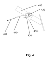
- FIG. 4 shows a side view of a driver's pedal 400 in the footwell of the driver's area of the motor vehicle.
- a pedal rider 410 is attached, which is shaped as a U-part, and is clamped on the pedal arm.
- a bolt 420 is attached, to which in turn a Seilklemmung is attached, which is movably mounted on the bolt.
- the cable 440 and 220 is fixed, which comes from the pulley from the adapter to the vehicle injection wall.
- the rope 220 and 440 is rolled up onto the roller 210 and a pulling force in the direction 450 is exerted on the driver pedal 400, whereby this driver pedal 400 is pulled down.
- FIG. 5 shows a side view of the driver's pedal 400 and 500 and a further attachment possibility of Seilzugiser 510 in the footwell of the driver area.
- the Seilzugiser can be a Bowden cable.
- the Seilzugiser with the cable guide 510 ie, the outer sheath of the Bowden cable
- the cable 220 can then be continued and secured with a cable clamp 540 and a bolt 550 around which the cable clamp is movably mounted.
- the bolt 550 can be attached to an adapter 560, in particular welded, which is attached, for example, at the bottom of the footwell of the driver's area of the vehicle. In this way not only can the cable 220 be fastened to the driver's pedal, but it is also possible to fasten a stable outer sheath of the cable-pulling unit to the driver's pedal without suffering any loss of the action of the
- the cable 220 can also be rotatably attached to the driver's pedal and can if possible be guided over a deflection roller, on the one hand the frictional resistance between cable 220 and a cable guide (not shown) As low as possible and the rope caused by the rotatable attachment to the driver's pedal no large rope loops.
- the proposed pedal system allows a variable output of the rope from the housing of the pedal system, which improves the connection of the Bowden cable, so that the installation flexibility of the pedal system over conventional pedal systems is greatly increased.
Landscapes
- Physics & Mathematics (AREA)
- General Physics & Mathematics (AREA)
- Engineering & Computer Science (AREA)
- Automation & Control Theory (AREA)
- Mechanical Control Devices (AREA)
Abstract
Description
Die vorliegende Erfindung bezieht sich auf eine Pedalanlage zur Bedienung eines Fahrzeugpedals eines Kraftfahrzeugs von der Beifahrerseite gemäß Anspruch 1.The present invention relates to a pedal system for operating a vehicle pedal of a motor vehicle from the passenger side according to claim 1.
In Übungsfahrzeugen von Fahrschulen ist es in einigen Ländern aus rechtlichen Gründen zwingend erforderlich, dass eine Doppelpedalanlage verbaut ist, um dem Fahrlehrer die Möglichkeit zu geben, bei Fahrfehlern der Fahrschüler rechtzeitig eingreifen und einen Verkehrsunfall verhindern zu können. Diese Doppelpedalanlage wird üblicherweise im Fußraum des Beifahrersitzplatzes verbaut. Die Pedale der Doppelpedalanlage werden mit den entsprechenden Pedalen im Fußraum des Fahrersitzes verbunden, beispielsweise mittels Wellentechnik über starre Verbindungen oder Kunststoffseilzügen. Seilzüge, insbesondere Bowdenzüge, bieten dabei den Vorteil, dass sie nur wenig Wartung erfordern und zuverlässig funktionieren. Allerdings besteht in herkömmlichen Doppelpedalanlagen mit Seilzügen der Nachteil, dass zur ausreichenden Kraftentwicklung beim Durchtreten des Pedals auf der Beifahrerseite entweder ein großer Pedalweg zurückgelegt werden muss oder eine komplizierte Übersetzung eines kleinen Pedalwegs in der Doppelpedalanlage erforderlich ist. Ein großer Pedalweg ist einerseits jedoch für den Fahrlehrer wenig komfortabel und andererseits bestehen Sicherheitsrisiken, wenn der Fahrlehrer das entsprechende Pedal der Doppelpedalanlage zu spät oder nicht ausreichend weit durchdrückt. Eine komplizierte Übersetzung in der Doppelpedalanlage erfordert demgegenüber eine hohe Anzahl von benötigten mechanischen Bauteilen sowie ein hohen Platzbedarf für eine solche Doppelpedalanlage, die einen Großteil des Fußraums im Bereich des Beifahrersitzes einnehmen würde. Dieser hohe Platzbedarf schränkt den verfügbaren Fußraum für den Fahrlehrer ein, wodurch sich eine derartige Doppelpedalanlage ebenfalls als unkomfortabel für den Fahrlehrer erweist. Ferner ist eine Doppelpedalanlage mit einer komplizierten Übersetzung durch die hohe Anzahl von miteinander verbundenen Bauteilen auch störungsanfällig, was sich bei einer Fahrt im Straßenverkehr als sicherheitskritisch erweist.In practice vehicles of driving schools it is imperative in some countries for legal reasons that a double pedal system is installed, in order to give the driving instructor the possibility to intervene in case of driving errors of the driving pupil in time and to be able to prevent a traffic accident. This double pedal system is usually installed in the footwell of the passenger seat. The pedals of the double pedal system are connected to the corresponding pedals in the footwell of the driver's seat, for example by means of shaft technology via rigid connections or plastic cable trains. Cables, especially Bowden cables, offer the advantage that they require little maintenance and work reliably. However, in conventional double pedal systems with cables has the disadvantage that sufficient force when passing the pedal on the passenger side either a large pedal travel must be covered or a complicated translation of a small pedal travel in the double pedal system is required. On the one hand, however, a great pedal travel is not very comfortable for the driving instructor and on the other hand there are safety risks if the driving instructor pushes the corresponding pedal of the double pedal system too late or not sufficiently far. In contrast, a complicated translation in the double pedal system requires a large number required mechanical components and a large amount of space for such a double pedal system, which would occupy a large part of the footwell in the passenger seat area. This high space requirement restricts the available footwell for the instructor, whereby such a double pedal system also proves to be uncomfortable for the driving instructor. Furthermore, a double pedal system with a complicated translation by the high number of interconnected components is also prone to failure, which turns out to be safety-critical when driving in traffic.
Die Aufgabe der vorliegenden Erfindung besteht somit darin, die vorstehend genannten Nachteile zu überwinden und eine verbesserte Pedalanlage zur Bedienung eines Fahrzeugpedals eines Kraftfahrzeugs von der Beifahrerseite zu schaffen.The object of the present invention is thus to overcome the above-mentioned disadvantages and to provide an improved pedal system for operating a vehicle pedal of a motor vehicle from the passenger side.
Diese Aufgabe wird durch eine Pedalanlage gemäß Anspruch 1 gelöst.This object is achieved by a pedal system according to claim 1.
Die vorliegende Erfindung schafft eine Pedalanlage zur Bedienung eines Fahrzeugpedals eines Kraftfahrzeugs von der Beifahrerseite, wobei die Pedalanlage folgende Merkmale umfasst:
- eine Seilzugeinheit mit einem Seil, wobei die Seilzugeinheit mit einem Fahrzeugpedal auf der Fahrerseite koppelbar ist;
- eine mit der Seilzugeinheit verbundene Aufrolleinheit, die eine um eine Drehachse drehbar gelagerte Rolle umfasst, wobei die Rolle ausgebildet ist, um durch eine Drehung der Rolle um die Drehachse einen Zug auf das Seil auszuüben, um ein Fahrzeugpedal des Kraftfahrzeugs zu betätigen;
- einen Beifahrerpedalhebel; und
- eine Kraftübertragungseinheit, die den Beifahrerpedalhebel und die Aufrolleinheit in Bezug auf eine Kraftübertragung wirksam koppelt, wobei die Kraftübertragungseinheit ausgebildet ist, um durch eine beim Niederdrücken des Beifahrerpedalhebels auftretende Kraft die Drehung der Rolle um die Drehachse zu bewirken.
- a Seilzugeinheit with a rope, the Seilzugeinheit with a vehicle pedal on the driver side can be coupled;
- a retractor unit connected to the cable pulling unit and including a roller rotatably mounted about an axis of rotation, the roller being adapted to exert a tension on the cable by rotation of the roller about the axis of rotation to actuate a vehicle pedal of the motor vehicle;
- a passenger pedal lever; and
- a power transmission unit that operatively couples the passenger pedal lever and the retractor with respect to a power transmission, the power transmission unit configured to cause rotation of the roller about the rotational axis by a force occurring upon depression of the passenger pedal lever.
Die vorliegende Erfindung basiert auf der Erkenntnis, dass eine sicher funktionierende und zugleich kompakt aufzubauende Pedalanlage dadurch realisierbar ist, dass beim Niedertreten eines Beifahrerpedalhebels eine Kraft bereitgestellt wird, die mittels einer Kraftübertragungseinheit (die beispielsweise eine Kombination aus einer Kette und einem Zahnrad, einem Zahnriemen und einer Riemenscheibe oder eines Zahnradsegmentes und einem Zahnrad umfasst) in eine Drehungskraft überführt wird. Diese Drehungskraft kann zum Antreiben einer Rolle einer Aufrolleinheit verwendet werden, welche einen Zug auf ein Seil einer Seilzugeinheit ausübt, damit ein an der Seilzugeinheit befestigbares Pedal auf der Fahrerseite des Fahrzeugs niedergezogen wird. Durch den einfachen Kopplungsmechanismus der Kraftübertragungseinheit auf die Rolle, die günstigerweise an einer fixen Position im Gehäuse gehalten und lediglich um eine Drehachse drehbar gelagert ist, lässt sich die genannte kleine kompakte Bauform der Pedalanlage erreichen. Zugleich besteht ferner die Möglichkeit, durch die Wahl eines unterschiedlich großen Durchmessers beispielsweise des Zahnrads oder der Riemenscheibe im Vergleich zur Rolle eine Hebelwirkung auszunutzen, um eine ausreichend starke Zugkraft auf das Seil bereitzustellen und ein im eingebauten Zustand der Pedalanlage in ein Fahrzeug ein an der Seilzugeinheit befestigtes Pedal auf der Fahrerseite zuverlässig niederzuziehen.The present invention is based on the finding that a safely functioning and at the same time compact to build pedal system is feasible by the depression of a passenger pedal lever, a force is provided by a power transmission unit (for example, a combination of a chain and a gear, a timing belt and a pulley or a gear segment and a gear) is converted into a rotational force. This rotational force can be used for driving a reel of a reel unit which exerts a pull on a cable of a cable reel unit, so that a pedal attachable to the cable reel unit is pulled down on the driver side of the vehicle. Due to the simple coupling mechanism of the power transmission unit on the roller, which is conveniently held in a fixed position in the housing and rotatably supported only about a rotation axis, said small compact design of the pedal system can be achieved. At the same time there is also the possibility to leverage by selecting a different diameter, for example, the gear or the pulley compared to the role to provide a sufficiently strong tensile force on the rope and a in the installed state of the pedal system in a vehicle on the Seilzugeinheit reliably fasten the attached pedal on the driver's side.
Günstig ist es auch, wenn die Kraftübertragungseinheit ausgebildet ist, um beim Niederdrücken des Beifahrerpedalhebels eine Kraft auf ein Kraftübertragungselement auszuüben und die ausgeübte Kraft mittels eines radförmigen Kraftaufnahmeelementes in eine Drehungskraft um die Drehachse umzuwandeln, um die Drehachse anzutreiben. Auf diese Weise kann eine einfache Antriebsvorrichtung zum Bewegen der Rolle der Aufrolleinheit geschaffen werden, die eine kompakte Bauform der Pedalanlage ermöglicht.It is also favorable if the force transmission unit is designed to exert a force on a force transmission element when depressing the passenger pedal lever and to convert the force exerted by means of a wheel-shaped force receiving element into a rotational force about the axis of rotation in order to drive the axis of rotation. In this way, a simple drive device for moving the roll of the retractor can be created, which allows a compact design of the pedal system.
In einer anderen Ausführungsform der vorliegenden Erfindung kann die Kraftübertragungseinheit oder das radförmige Kraftaufnahmeelement über eine Wellenverbindung mit der Drehachse der Rolle gekoppelt sein. Insbesondere kann das radförmige Kraftübertragungselement durch eine starre Verbindung mit der Drehachse verbunden sein. Hierdurch wird ein Vorteil erzielt, derart, dass eine Kraftübertragung durch eine einfache und kleine Bauform in der Pedalanlage realisiert werden kann, ohne komplexe Getriebe zur Kraftübersetzung oder eine Anpassung der Zugstrecke implementieren zu müssen.In another embodiment of the present invention, the power transmission unit or the wheel-shaped force receiving element may be coupled via a shaft connection with the axis of rotation of the roller. In particular, the wheel-shaped power transmission element can be connected by a rigid connection with the axis of rotation. As a result, an advantage is achieved, such that a power transmission by a simple and small design in the pedal system can be realized without having to implement complex transmission for power transmission or an adjustment of the train route.
Insbesondere kann die Kraftübertragungseinheit in einer günstigen Ausführungsform der Erfindung eine Kette und ein Zahnrad umfassen, wobei die Kette mit dem Beifahrerpedalhebel koppelbar und über das Zahnrad führbar ist, und wobei beim Niederdrücken des Beifahrerpedalhebels die Kette eine Zugkraft auf das Zahnrad ausübt, welches eine Drehung der Rolle der Aufrolleinheit bewirkt. Eine derartige Ausführungsform der vorliegenden Erfindung bietet den Vorteil, dass die Kraftübertragung zwischen Beifahrerpedalhebel und Aufrolleinheit zuverlässig auch bei größeren zu übertragenden Kräften möglich ist. Durch das Zahnrad kann weiterhin auf einfache Weise eine Zugkraft in einer Drehungskraft überführt werden.In particular, the power transmission unit may comprise a chain and a gear in a favorable embodiment of the invention, wherein the chain with the passenger pedal lever and the gear is negotiable, and wherein upon depression of the passenger pedal lever, the chain exerts a tensile force on the gear, which rotation of the Roll of the reeling unit causes. Such an embodiment of the present invention has the advantage that the power transmission between the passenger pedal lever and the take-up unit is reliably possible even with larger forces to be transmitted. By the gear can continue to be transferred in a simple manner, a tensile force in a rotational force.
Alternativ kann auch die Kraftübertragungseinheit einen Zahnriemen und eine Riemenscheibe umfassen, wobei der Zahnriemen mit dem Beifahrerpedalhebel koppelbar und über die Riemenscheibe führbar ist, wobei beim Niederdrücken des Beifahrerpedalhebels der Zahnriemen eine Zugkraft auf die Riemenscheibe ausübt, welche eine Drehung der Rolle der Aufrolleinheit bewirkt. Auch eine derartige Ausführungsform der vorliegenden Erfindung bietet den Vorteil, dass die Kraftübertragung zwischen Beifahrerpedalhebel und Aufrolleinheit zuverlässig auch bei größeren zu übertragenden Kräften möglich ist. Auch durch die Riemenscheibe kann weiterhin auf einfache Weise eine Zugkraft in einer Drehungskraft überführt werden.Alternatively, the power transmission unit may also comprise a toothed belt and a pulley, the toothed belt being couplable and passable via the pulley, wherein upon depression of the front passenger pedal lever the toothed belt exerts a pulling force on the pulley which causes rotation of the roller of the takeup unit. Such an embodiment of the present invention also offers the advantage that the power transmission between the passenger pedal lever and the retracting unit is reliably possible even with larger forces to be transmitted. Also by the pulley can continue to be transferred in a simple manner, a tensile force in a rotational force.
Ferner kann die Kraftübertragungseinheit gemäß einer weiteren Ausführungsform der Erfindung ein Zahnradsegment und ein Zahnrad umfassen, wobei das Zahnradsegment mit dem Beifahrerpedalhebel koppelbar und derart mit dem Zahnrad anordenbar ist, dass Zähne des Zahnradsegmentes Eingriff in das Zahnrad nehmen, wobei das Zahnradsegment ferner derart befestigbar ist, dass beim Niederdrücken des Beifahrerpedalhebels das Zahnradsegment eine Kraft auf das Zahnrad ausübt, welches die Kraft in eine Drehungskraft umwandelt, um eine Drehung der Rolle der Aufrolleinheit zu bewirken. Auch eine derartige Ausführungsform der vorliegenden Erfindung bietet den Vorteil, dass die Kraftübertragung zwischen Beifahrerpedalhebel und Aufrolleinheit zuverlässig auch bei größeren zu übertragenden Kräften möglich ist. Hierbei ist anzumerken, dass sowohl ein Zahnradsegment mit nach innen gerichteten Zähnen als auch ein Zahnradsegment mit nach außen gerichteten Zähnen verwendet werden kann, wobei das Zahnrad, das die Drehachse antreiben kann derart angeordnet ist, dass es entsprechend Eingriff in die innen oder außen gerichteten Zähne nehmen kann. Durch die Kombination zwischen dem Zahnradsegment und dem Zahnrad kann weiterhin auf einfache Weise eine Kraft vom Beifahrerpedalhebel in einer Drehungskraft überführt werden, wobei der Verschleiß durch die Verwendung von nicht-elastischen Elementen wie dem Zahnradsegment und dem Zahnrad reduziert werden kann.Furthermore, according to a further embodiment of the invention, the power transmission unit can comprise a gear segment and a gear, wherein the gear segment can be coupled to the passenger pedal lever and can be arranged with the gear in such a way that teeth of the gear segment engage in the gear, wherein the gear segment can also be fastened in such a way, that upon depression of the passenger pedal lever, the gear segment exerts a force on the gear which converts the force into a rotational force to effect rotation of the reel unit reel. Also, such an embodiment of the present invention offers the advantage that the power transmission between the passenger pedal lever and retractor reliably even at larger forces to be transmitted is possible. It should be noted that both a gear segment with inwardly directed teeth and a gear segment with outwardly directed teeth may be used, wherein the gear which can drive the rotation axis is arranged such that it engages the inside or outside teeth accordingly can take. Further, the combination between the gear segment and the gear can easily transfer a force from the passenger pedal lever in a rotational force, whereby the wear can be reduced by the use of non-elastic members such as the gear segment and the gear.
Auch kann in einer anderen Ausführungsform der Erfindung die Aufrolleinheit ausgebildet sein, um die Drehachse der Rolle bei einem Niederdrücken des Beifahrerpedalhebels in einer vorbestimmten fixen Position bezüglich des Gehäuses der Pedalanlage zu halten. Eine derartige Ausführungsform der vorliegenden Erfindung bietet den Vorteil, dass die Rolle als größere Komponente der Pedalanlage in einem Gehäuse der Pedalanlage fixiert positioniert bleibt, so dass sich der Platzbedarf einer solchen Pedalanlage durch den vermiedenen Bewegungsspielraum auf ein Minimum reduziert.Also, in another embodiment of the invention, the retractor may be configured to hold the axis of rotation of the roller upon depression of the passenger pedal lever in a predetermined fixed position relative to the housing of the pedal assembly. Such an embodiment of the present invention has the advantage that the role remains fixed as a larger component of the pedal system fixed in a housing of the pedal system, so that reduces the space requirement of such a pedal system by the avoided range of motion to a minimum.
Gemäß einer anderen Ausführungsform Erfindung kann die Kraftübertragungseinheit ein ketten- oder riemenförmiges Zugkraftübertragungselement aufweisen, dessen eines Ende mit dem Beifahrerpedalhebel koppelbar ist und dessen anderes Ende mittels eines elastischen Rückzugselementes an einem Gehäuse der Pedalanlage auf Zug befestigbar ist. Durch das Vermeiden eines umlaufenden Zugkraftübertragungselements wird dieses Zugkraftübertragungselement somit klein und platzsparend gehalten. Trotzdem kann durch die Verwendung des elastischen Rückzugselements sichergestellt werden, dass sich bei einem Loslassen des Beifahrerpedalhebels die Elemente der Kraftübertragungseinheit wieder die Ausgangslage begeben.According to another embodiment of the invention, the power transmission unit may comprise a chain or belt-shaped tensile force transmitting element, one end of which is couplable to the passenger pedal lever and the other end of which can be fastened to a housing of the pedal system by train by means of an elastic retraction element. By avoiding a circumferential traction transfer element, this tensile force transmission element is thus kept small and space-saving. Nevertheless, it can be ensured by the use of the elastic retraction element that, when the passenger pedal lever is released, the elements of the power transmission unit return to the starting position.
Wenn das Fahrerpedal durchgetreten ist, während das Beifahrerpedal nicht durchgetreten ist, würde das Seil im Fußraum des Fahrerbereiches schlaff durchhängen. Dies kann verhindert werden, wenn die Kraftübertragungseinheit eine Seilrückzugseinheit aufweist, die ausgebildet ist, um eine Bewegung der Rolle der Aufrolleinheit zu bewirken und hierdurch einen Zug auf das Seil auszuüben, wenn sich der Beifahrerpedalhebel in einer Ruheposition befindet.If the driver's pedal has been depressed while the passenger's pedal has not worn, the rope in the footwell of the driver's area would sag slack. This can be prevented if the power transmission unit has a cable retraction unit, which is designed to prevent movement of the Role of the reel unit and thereby exert a pull on the rope when the passenger pedal lever is in a rest position.
Eine einfache Konfiguration der Seilrückzugseinheit kann auf eine Weise realisiert werden, indem die Seilrückzugseinheit ein Seilrückzugselement aufweist, welches beweglich am Beifahrerpedalhebel befestigt ist, wobei die Seilrückzugseinheit ausgebildet sein kann, um die Bewegung der Rolle der Aufrolleinheit durch eine Bewegung des Seilrückzugselementes in Bezug zum Beifahrerpedalhebel zu bewirken. Hierdurch kann eine Kombination der kompakten Bauform der Pedalanlage sichergestellt werden, die sowohl eine Funktionalität des Seilzugs bei einem Betätigen des Beifahrerpedalhebels als auch eine Funktionalität bezüglich des Seilrückzugs bei einem Durchtreten des Fahrerpedals ohne ein Durchtreten des Beifahrerpedalhebels zu ermöglichen.A simple configuration of the rope retracting unit may be realized in a manner in which the cable retracting unit has a cable retracting member movably mounted on the passenger pedal lever, the cable retracting unit being adapted to move the roller of the retracting unit by movement of the cable retracting member relative to the passenger pedal lever cause. In this way, a combination of the compact design of the pedal system can be ensured to allow both functionality of the cable when operating the passenger pedal lever and functionality with respect to the rope retraction in a passage of the driver pedal without a passage of the passenger pedal lever.
Auch kann gemäß einer anderen Ausführungsform der Erfindung die Kraftübertragungseinheit ferner ein Zugkraftübertragungselement aufweisen, das an dem Seilrückzugselement befestigt ist und wobei das Zugkraftübertragungselement in Bezug auf eine Kraftübertragung wirksam mit der Drehachse gekoppelt ist, um eine Drehung der Drehachse zu bewirken. Dies bietet den Vorteil, dass der Kraftübertragungsmechanismus sowohl für die Kraftübertragung beim Niedertreten des Beifahrerpedalhebels als auch beim Rückziehen des Seils aus dem Fußraum des Fahrerbereiches verwendet werden kann. Somit kann durch die Verwendung eines einzigen Bewegungsmechanismus für die Rolle der Aufrolleinheit der erforderliche Platzbedarf minimiert werden.Also, according to another embodiment of the invention, the power transmission unit may further include a traction transfer member secured to the cable retraction member, and wherein the traction transfer member is operatively coupled to the rotational axis with respect to power transmission to effect rotation of the rotational axle. This offers the advantage that the power transmission mechanism can be used both for the power transmission when depressing the passenger pedal lever and when retracting the rope from the footwell of the driver area. Thus, by using a single movement mechanism for the reel unit's role, the space required can be minimized.
Auch kann in einer anderen Ausführungsform der Erfindung der Beifahrerpedalhebel einen Mitnehmer-Stift aufweisen, der ausgebildet ist, um eine Position des Seilrückzugselements in Bezug zum Beifahrerpedalhebel beim Niederdrücken des Beifahrerpedalhebels zu fixieren und um bei einem Loslassen des Beifahrerpedalhebels das Seilrückzugselement in Bezug zum Beifahrerpedalhebel freizugeben. Dies stellt eine einfache jedoch sehr wirkungsvolle Maßnahme dar, um sicherzustellen, dass das Seilrückzugselement sowohl beim Niedertreten des Beifahrerpedalhebels als auch beim Seilrückzug wie gewünscht funktioniert, wobei die Funktionalität des Seilrückzugs beim Niedertreten des Beifahrerpedalhebels Priorität gegenüber dem Seilrückzug beim Durchtreten des Fahrerpedals hat.Also, in another embodiment of the invention, the passenger pedal lever may include a follower pin configured to fix a position of the cable retraction member relative to the passenger pedal lever upon depression of the passenger pedal lever and to release the cable retraction member relative to the passenger pedal lever upon release of the passenger pedal lever. This is a simple but very effective measure to ensure that the cable retraction element works both when depressing the passenger pedal lever and the cable retraction as desired, the functionality of the cable retraction when depressing the passenger pedal lever Priority over the rope retraction when passing the driver's pedal has.
Um sicherzustellen, dass das Seilrückzugselement eine gewisse Vorspannung aufweist, die es ermöglicht, sofort nach dem Niedertreten des Fahrerpedals ein durchhängendes Seil im Fußraum des Fahrerbereiches hängendes Seil zurückzuziehen, kann das Seilrückzugselement mittels eines Federelementes mit dem Gehäuse der Pedalanlage koppelbar sein. Eine derartige Ausführungsform der vorliegenden Erfindung bietet den Vorteil, dass eine sehr platzsparende Seilrückzugsmöglichkeit in der Pedalanlage integrierbar ist. Zugleich wird auf diese Weise sichergestellt, dass eine ständige Zugbereitschaft des Seilrückzugselements gewährleistet ist, so dass bei einem Niedertreten des Pedals auf der Fahrerseite ein durchhängendes Seil sofort aus dem Fußraum im Fahrerbereich zurückgezogen wird.To ensure that the cable retraction element has a certain bias, which makes it possible to immediately withdraw a sagging rope in the footwell of the driver's area hanging rope after depressing the driver's pedal, the cable retraction element can be coupled by means of a spring element with the housing of the pedal system. Such an embodiment of the present invention has the advantage that a very space-saving cable retraction option is integrated in the pedal system. At the same time it is ensured in this way that a constant Zugbereitschaft the rope retracting element is guaranteed, so that when depressing the pedal on the driver's side a sagging rope is immediately withdrawn from the footwell in the driver area.
Alternativ kann auch die Seilrückzugseinheit ein elastisches Federelement aufweisen, welches an der Rolle der Aufrolleinheit befestigbar ist. Hierdurch wird es möglich, ein durchhängendes Seil im Fußraum des Fahrerbereichs durch ein direktes Bewegen der Rolle der Aufrolleinheit zurückzuziehen, ohne dass ein drehbar am Beifahrerpedalhebel befestigtes Seilrückzugselement verwendet werden braucht. Allerdings ist in diesem Fall sicherzustellen, dass die Aufrolleinheit ein entsprechendes Freilauf-Getriebe aufweist, um die Rückzugsbewegung des Seiles auch ohne die Betätigung des Beifahrerpedalhebels zu ermöglichen..Alternatively, the cable retraction unit can also have an elastic spring element, which can be fastened to the roller of the retraction unit. This makes it possible to retract a sagging rope in the footwell of the driver area by directly moving the role of the take-up unit, without the need for rotatably attached to the passenger pedal lever cable retraction element needs to be used. However, in this case, it must be ensured that the take-up unit has a corresponding free-wheeling transmission in order to enable the return movement of the cable even without the operation of the passenger pedal lever.
Um eine schnelle und sichere Seilführung im Fußraum des Fahrerbereiches sicherzustellen, kann die Seilzugeinheit eine auf der Fahrerseite befestigbare Umlenkrolle und eine Seilbefestigungseinheit zur Befestigung des Seils oder der Seilzugeinheit am Fahrzeugpedal umfassen, wobei die Seilbefestigungseinheit ausgebildet ist, um das Seil am Fahrzeugpedal drehbar gelagert zu befestigen. Durch die Verwendung einer derartigen Ausführungsform der vorliegenden Erfindung wird sichergestellt, dass eine Seilschlaufe im Fußraum des Fahrerbereichs durch die drehbare Befestigung am Fahrerpedal möglichst gering gehalten wird, um ein gutes Gleiten des Seiles sicherzustellen und ein Verknoten des Seiles in diesem Bereich effektiv zu verhindern.To ensure fast and safe cable guidance in the footwell of the driver's area, the cable pull unit can comprise a driver's side attachable pulley and a cable attachment unit for attaching the cable or Seilzugeinheit on the vehicle pedal, wherein the cable attachment unit is designed to fasten the cable rotatably mounted on the vehicle pedal , The use of such an embodiment of the present invention ensures that a cable loop in the footwell of the driver's area is kept as low as possible by the rotatable attachment to the driver's pedal to ensure a good sliding of the rope and effectively prevent knotting the rope in this area.
In einer anderen Ausführungsform der Erfindung, bei der der Beifahrerpedalhebel an einem Drehpunkt in einem Gehäuse der Pedalanlage drehbar befestigt ist, kann die Kraftübertragungseinheit ein mit dem Beifahrerpedalhebel koppelbares und zwischen dem Drehpunkt und der Drehachse angeordnetes Zugkraftübertragungselement aufweisen. Insbesondere dann, wenn das Seil der Seilzugeinheit im Bereich des Drehpunkts einem Gehäuse der Pedalanlage verlässt, bietet eine derartige Ausführungsform der vorliegenden Erfindung den Vorteil, dass beim Niedertreten des Beifahrerpedalhebels die Rolle (beispielsweise mittels des Zahnrads oder der Riemenscheibe) bereits ohne Übersetzung in eine Richtung gedreht wird, durch die ein Zug auf das Seil ausgeübt wird. Somit kann ein Übersetzungsgetriebe zur Anpassung der Drehrichtung vermieden werden, wodurch sich der erforderliche Platzbedarf für die Pedalanlage minimieren lässt.In another embodiment of the invention, wherein the passenger pedal lever is rotatably mounted at a pivot point in a housing of the pedal system, the power transmission unit may comprise a coupled with the passenger pedal lever and arranged between the pivot point and the axis of rotation traction element. In particular, when the cable of Seilzugeinheit leaves a housing of the pedal system in the region of the pivot point, such an embodiment of the present invention offers the advantage that when depressing the passenger pedal lever, the role (for example by means of the gear or the pulley) already without translation in one direction is rotated by a train is applied to the rope. Thus, a transmission gear to adjust the direction of rotation can be avoided, which can minimize the space required for the pedal system.
In einer anderen Ausführungsform der Erfindung kann die Kraftübertragungseinheit ein mit der Drehachse verbundenes radförmiges Kraftübertragungselement umfassen, welches einen äußeren Durchmesser aufweist, der kleiner als der Durchmesser der Rolle ist. Eine derartige Ausführungsform der von den Erfindung bietet den Vorteil, dass durch die Ausnutzung des Hebelgesetzes auch eine kleine Zugstrecke eines Zugkraftelementes der Kraftübertragungseinheit eine Bewegung des Seils um eine Strecke ermöglicht, die ausreicht, um ein Pedal an der Fahrerseite niederzuziehen.In another embodiment of the invention, the power transmission unit may comprise a wheel-shaped power transmission element connected to the rotation axis and having an outer diameter smaller than the diameter of the roller. Such an embodiment of the invention provides the advantage that by utilizing the lever law, even a small pulling distance of a traction element of the power transmission unit allows movement of the rope by a distance sufficient to pull down a pedal on the driver's side.
Eine einfache Konfiguration der Seilrückzugseinheit kann auf eine Weise realisiert werden, indem die Seilrückzugseinheit ein Seilrückzugselement aufweist, welches beweglich am Beifahrerpedalhebel befestigt ist, wobei die Kraftübertragungseinheit ferner ein Zugkraftübertragungselement aufweist, das an dem Seilrückzugselement befestigt ist. Auf diese Weise ist es möglich, dass das Seilrückzugselement auch eine Zugkraft auf das Zugkraftübertragungselement ausübt, wenn der Beifahrerpedalhebel nicht durchgedrückt ist. Beispielsweise kann das Seilrückzugselement durch eine Feder oder einen Gummi ausgelenkt werden, wenn der Beifahrerpedalhebel nicht durchgedrückt ist. Die Zugkraft wird in diesem Fall durch die Feder oder den Gummi auf das Zugkraftübertragungselement ausgeübt.A simple configuration of the cable retraction unit can be realized in a manner in that the cable retraction unit comprises a cable retracting member which is movably mounted on the passenger pedal lever, wherein the power transmission unit further comprises a tensile force transmitting member which is fixed to the cable retraction member. In this way, it is possible that the cable retraction element also exerts a tensile force on the traction transfer element when the passenger pedal lever is not pushed. For example, the cable retraction element can be deflected by a spring or a rubber when the passenger pedal lever is not pushed through. The tensile force is exerted in this case by the spring or the rubber on the tensile force transmission element.
Auch kann in einer günstigen Ausführungsform der Erfindung das elastische Federelement an einer Befestigungsmöglichkeit im unteren Teilbereich des Seilrückzugselementes, in eine Niederdrück-Richtung gesehen, befestigbar sein. Eine derartige Ausführungsform der Erfindung bietet den Vorteil, dass das elastische Federelement möglichst weit entfernt von einem Drehpunkt des Seilrückzugselements am Beifahrerpedalhebel angreift, um auf diese Weise durch Ausnutzung des Hebelgesetzes eine möglichst große Kraft auf das Seilrückzugselement bzw. das Zugkraftübertragungselement ausüben zu können.Also, in a favorable embodiment of the invention, the elastic spring element at a mounting possibility in the lower portion of the cable retraction element, seen in a depression direction, be fastened. Such an embodiment of the invention has the advantage that the elastic spring element as far away from a pivot point of the cable retraction element acts on the passenger pedal lever to exercise in this way by utilizing the lever law as large a force on the cable retraction element or the traction transmission element.
Ein Ausführungsbeispiel der vorliegenden Erfindung ist nachfolgend unter Verwendung der beigefügten Zeichnungen näher erläutert. Hierbei zeigt
- Figur 1
- eine Querschnittsdarstellung von Komponenten einer Pedalanlage, bei der sich ein Beifahrerpedal und ein an der Seilzugeinheit befestigtes Fahrerpedal in Ruhestellung befinden;
- Figur 2
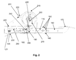
- eine Querschnittsdarstellung von Komponenten der Pedalanlage, bei der sich ein Beifahrerpedal ein an der Seilzugeinheit befestigtes Fahrerpedal in einem durchgetretenen Zustand befinden;
- Figur 3
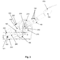
- eine Querschnittsdarstellung von Komponenten der Pedalanlage, bei der sich ein Beifahrerpedal in der Ruhestellung befindet, bei der jedoch ein Pedal auf der Fahrerseite durchgetreten ist;
- Figur 4
- eine Seitenansicht eines Befestigungsmechanismus der Seilzugeinheit am Fahrerpedal; und
- Figur 5
- eine Seitenansicht einer weiteren Befestigungsmöglichkeit der Seilzugeinheit im Fußraum auf der Fahrerseite.
- FIG. 1
- a cross-sectional view of components of a pedal system, in which a passenger pedal and attached to the Seilzugeinheit driver pedal are at rest;
- FIG. 2
- a cross-sectional view of components of the pedal system in which a passenger's pedal is attached to the Seilzugeinheit driver pedal in a well-worn state;
- FIG. 3
- a cross-sectional view of components of the pedal system, in which a passenger's pedal is in the rest position, but in which a pedal has passed through on the driver's side;
- FIG. 4
- a side view of a fastening mechanism of Seilzugeinheit on the driver's pedal; and
- FIG. 5
- a side view of a further possibility of attachment of Seilzugeinheit in the footwell on the driver side.
Eventuell angegebene Dimensionen und Maße sind nur exemplarisch, so dass die Erfindung nicht auf diese Dimensionen und Maße beschränkt ist. Gleiche oder ähnliche Elemente sind mit gleichen oder ähnlichen Bezugszeichen versehen. Ferner enthalten die Figuren der Zeichnungen, deren Beschreibung sowie die Ansprüche zahlreiche Merkmale in Kombination. Einem Fachmann ist dabei klar, dass diese Merkmale auch einzeln betrachtet werden können oder sie zu weiteren, hier nicht explizit beschriebenen Kombinationen zusammengefasst werden können.Any dimensions and dimensions given are exemplary only, so the invention is not limited to these dimensions and dimensions. The same or similar elements are provided with the same or similar reference numerals. Furthermore, the figures of the drawings, the description and the claims contain numerous features in combination. A specialist is involved It is clear that these features can also be considered individually or that they can be combined to form further combinations which are not explicitly described here.
Eine Komponentenanordnung, wie sie in Querschnittsdarstellung gemäß
Das Kettenblockelement 180 kann auf Grund seiner Funktionalität auch als Seilrückzugselement bezeichnet werden und kann derart ausgebildet sein, dass ein Mitnehmer-Stift 240 in eine Ausnehmung 250 dieses Elements 180 eingreift und dieses Element 180 beim Niedertreten des Beifahrerpedalhebels 110 "mitnimmt" (d.h. in einer entsprechenden Position in Bezug zum Beifahrerpedalhebel 110 fixiert) und das Kettenblockelement 180 bei der Rückführung des Beifahrerpedalhebels 110 in seine Ausgangslage freigibt. Die Pedalanlage 100 kann ferner ein Federelement 260 umfassen (das auch anderes geeignetes elastisches Element wie beispielsweise ein Gummi sein kann), welches an dem Gehäuse 130 sowie beispielsweise einem unteren Teilbereich (in Niederdrück-Richtung gesehen) an dem Kettenblockelement 180 befestigt ist. Somit wird durch die (vorzugsweise einstellbare) Federkraft des Federelements 260 eine ständige leichte Zugkraft auf das Kettenblockelement 180 nach unten ausgeübt, um die nachfolgend näher genannten Vorteile beim Rückziehen des Seiles 220 ohne Betätigung des Beifahrerpedalhebels 110 zu ermöglichen.The
Die Funktionsweise der Pedalanlage 100 kann unter Verwendung von
Das Zahnrad 200 treibt insbesondere über eine starre Verbindung direkt die Achse bzw. Narbe der Seilrolle 210 an, so dass auch ein Übersetzungsgetriebe entfallen kann, welches einen zusätzlichen Platzbedarf erfordern würde. Alternativ kann natürlich auch zur Verbesserung der erforderlichen Kraft oder der erforderlichen Zugstrecke auch ein entsprechend geeignetes Übersetzungsgetriebe verwendet werden. Um eine Zugkraft von der Seilrolle 210 auf das Seil 220 auszuüben, ist gemäß der Anordnung aus
Um beim Loslassen der Trittplatte 170 durch den Fahrlehrer die Komponenten der Pedalanlage 100 in die in
Ferner kann auch ein in
Um die Betätigung der Seilrolle 210 bei einem Niederdrücken des Beifahrerpedalhebels 110 sicherzustellen, kann alternativ zu der Kombination Kette-Zahnrad auch eine Kombination Zahnriemen-Riemenscheibe verwendet werden, die ein physikalisch analoges Wirkungsprinzip realisieren. Gemäß einem weiteren Ausführungsbeispiel der vorliegenden Erfindung kann auch statt dem Seilrückzugselement 180 und der Kette 190 ein Zahnradsegment verwendet werden. In einem solchen Ausführungsbeispiel (welches vorliegend allerdings nicht bildlich dargestellt ist) greifen dann die Zähne des Zahnradsegmentes in die Zähne des Zahnrades ein, welches die Rolle 210 antreiben kann und dessen Drehung bewirkt. Dabei können die Zähne des Zahnradsegmentes entweder auf einer äußeren Seite oder einer inneren Seite des Zahnradsegmentes angeordnet sein, je nachdem welche Drehrichtung für die Rolle gewünscht wird. Ferner kann auch über die Variation der Größe des Radius des Zahnradsegmentes in Bezug zum Zahnrad eine günstige Hebelwirkung sowie eine optimale Seilzugstrecke erreicht werden.To ensure the operation of the
Als weitere Funktionalität der Pedalanlage 100 sollte auch sichergestellt sein, dass bei einer Betätigung des Fahrerpedal durch den Fahrschüler das Seil 220 aus dem Fußraum des Fahrerbereichs herausgezogen wird. Hierdurch wird sichergestellt, dass das Seil 220 im Fußraum des Fahrerbereichs keine Verschlingung bildet, wodurch ein mögliches Blockieren des Fahrerpedals verhindert werden kann. Das Rückziehen des Seiles 220 erfolgt gemäß der Darstellung aus
Um eine möglichst große Hebelwirkung zu erreichen, sollte das elastische Federelement 260 möglichst weit an einem (unteren) Rand des Seilrückzugselements 180 und möglichst weit entfernt (beispielsweise im Bereich der Hälfte des Seilrückzugselements 180 in Erstreckung längs zum Beifahrerpedalhebel 110) von einem drehbaren Befestigungspunkt des Seilrückzugselements 180 am Beifahrerpedalhebel 110 angreifen. Dies hat den Vorteil, dass bei anfänglicher kleiner Zugkraft bereits eine kleine Auslenkung des Seilrückzugselements 180 gegenüber der Ausrichtung des Beifahrerpedalhebels 110 dazu führt, dass eine möglichst große Zugkraft durch das Federelement 260 auf die Kette 190 ausgeübt werden kann.In order to achieve the greatest possible leverage, the
Alternativ oder zusätzlich zu dem in den
Die
Um beim Aufrollen eines durchhängenden Seils 220 im Fußraum des Fahrerbereiches eine optimale Seilführung sicherzustellen, kann das Seil 220 auch drehbar an dem Fahrerpedal befestigt sein und kann möglichst über eine Umlenkrolle geführt werden, damit einerseits der Reibungswiderstand zwischen Seil 220 und einer (nicht dargestellten) Seilführung möglichst gering ist und das Seil durch die drehbare Befestigung am Fahrerpedal keine großen Seilschlaufen entstehen.In order to ensure optimum cable guidance when rolling up a sagging
Zusammenfassend ist anzumerken, dass bei den in den Figuren dargestellten Ausführungsbeispielen beim Treten des Pedals 170 die Kraft über einen Hebelhalter 110 mit Bolzen 240 auf eine die Kette 190 übertragen wird. Durch das Ziehen an der Kette 190 werden das Zahnrad 200 und die Seilrolle 210 gedreht. Dabei sind Zahnrad 200 und Seilrolle 210 vorzugsweise fest verbunden und drehen sich auf einer gemeinsamen Welle 205. Dadurch wird das Seil 220 auf der Seilrolle 210 aufgewickelt und somit das Pedal betätigt, das im verbauten Zustand der Pedalanlage an dem Seil 220 auf der Fahrerseite gefestigt ist.In summary, it should be noted that in the embodiments illustrated in the figures when pedaling the
Die Kombination Kette 190, Kettenrad 200 und Seilrolle 210 kann auch mit Zahnriemen und Riemenscheiben realisiert werden. Auch kann eine Übersetzung mit Zahnrädern bzw. einem Zahnradsegment und einem Zahnrad realisiert werden.The
Wenn das Pedal auf der Fahrerseite betätigt wird, wird das lockere Seil 220 durch ein Federelement 260 am Kettenblock 180 über die Kette 190, Zahnrad 200 und Seilrolle 210 zurückgezogen. Dies lässt sich auch realisieren in dem man ein Federelement direkt an der Seilrolle 210 angreifen lässt.When the driver-side pedal is actuated, the
Durch die vorstehend vorgeschlagene Pedalanlage kann auf der Beifahrerseite ein kurzer Pedalweg bei einer kleinen kompakten Bauform der Pedalanlage erreicht werden. Zugleich ist lediglich ein geringer Kraftaufwand erforderlich, um das Pedal auf der Beifahrerseite bedienen zu können. Auch ermöglicht die vorgeschlagene Pedalanlage einen variablen Ausgang des Seils aus dem Gehäuse der Pedalanlage, was die Anbindung des Bowdenzugs verbessert, so dass die Einbauflexibilität der Pedalanlage gegenüber herkömmlichen Pedalanlagen stark erhöht ist.By the above-proposed pedal system can be achieved on the passenger side, a short pedal travel in a small compact design of the pedal system. At the same time only a small amount of force is required to operate the pedal on the passenger side. Also, the proposed pedal system allows a variable output of the rope from the housing of the pedal system, which improves the connection of the Bowden cable, so that the installation flexibility of the pedal system over conventional pedal systems is greatly increased.
Claims (15)
Priority Applications (2)
| Application Number | Priority Date | Filing Date | Title |
|---|---|---|---|
| EP08170198A EP2192468A1 (en) | 2008-11-28 | 2008-11-28 | Pedal assembly for operating a vehicle pedal of a motor vehicle from the passenger side |
| DE200910047257 DE102009047257A1 (en) | 2008-11-28 | 2009-11-27 | Pedal system for operating a vehicle pedal of a motor vehicle from the passenger side |
Applications Claiming Priority (1)
| Application Number | Priority Date | Filing Date | Title |
|---|---|---|---|
| EP08170198A EP2192468A1 (en) | 2008-11-28 | 2008-11-28 | Pedal assembly for operating a vehicle pedal of a motor vehicle from the passenger side |
Publications (1)
| Publication Number | Publication Date |
|---|---|
| EP2192468A1 true EP2192468A1 (en) | 2010-06-02 |
Family
ID=40568791
Family Applications (1)
| Application Number | Title | Priority Date | Filing Date |
|---|---|---|---|
| EP08170198A Withdrawn EP2192468A1 (en) | 2008-11-28 | 2008-11-28 | Pedal assembly for operating a vehicle pedal of a motor vehicle from the passenger side |
Country Status (2)
| Country | Link |
|---|---|
| EP (1) | EP2192468A1 (en) |
| DE (1) | DE102009047257A1 (en) |
Families Citing this family (3)
| Publication number | Priority date | Publication date | Assignee | Title |
|---|---|---|---|---|
| DE102017001554B4 (en) * | 2017-02-20 | 2019-01-17 | Ceylan Ates | Double operation with decoupling device |
| DE102019210332B4 (en) * | 2019-07-12 | 2021-02-04 | Audi Ag | Device for adjusting a pedal arrangement |
| DE102019210675B4 (en) * | 2019-07-19 | 2021-03-25 | Audi Ag | Device for adjusting a pedal arrangement |
Citations (10)
| Publication number | Priority date | Publication date | Assignee | Title |
|---|---|---|---|---|
| US2670822A (en) * | 1951-04-09 | 1954-03-02 | James T Reilly | Accelerator setting control |
| US2710547A (en) * | 1952-09-10 | 1955-06-14 | Alvan F Davenport | Dual control apparatus |
| DE1931798U (en) * | 1964-11-18 | 1966-01-27 | Alfred Kubik | DOUBLE OPERATING DEVICE FOR VEHICLES. |
| EP0515160A1 (en) * | 1991-05-21 | 1992-11-25 | Morse Controls Limited | Remote control mechanisms |
| DE4226962A1 (en) * | 1992-08-14 | 1994-02-17 | Wolfram Schirrmann | Double pedal device for a driving school car |
| BE1010871A6 (en) * | 1997-01-21 | 1999-02-02 | Mocian Diana | Removable dual control system for cars |
| EP0949554A2 (en) * | 1998-04-08 | 1999-10-13 | Wolfram Schirrmann | Dual pedal device for an instruction car |
| WO2002025394A1 (en) * | 2000-09-22 | 2002-03-28 | Karlheinz Pilz | Driving school vehicle, double pedal device, pedal box, adjuster and driving instructor post for use in the driving school vehicle |
| US20020078783A1 (en) * | 2000-12-22 | 2002-06-27 | Chang-Seob Bang | Acceleration pedal device of automobile |
| EP1674357A1 (en) * | 2004-12-27 | 2006-06-28 | Doosan Infracore Co., Ltd. | Common use pedal device for automotive vehicles |
-
2008
- 2008-11-28 EP EP08170198A patent/EP2192468A1/en not_active Withdrawn
-
2009
- 2009-11-27 DE DE200910047257 patent/DE102009047257A1/en not_active Withdrawn
Patent Citations (10)
| Publication number | Priority date | Publication date | Assignee | Title |
|---|---|---|---|---|
| US2670822A (en) * | 1951-04-09 | 1954-03-02 | James T Reilly | Accelerator setting control |
| US2710547A (en) * | 1952-09-10 | 1955-06-14 | Alvan F Davenport | Dual control apparatus |
| DE1931798U (en) * | 1964-11-18 | 1966-01-27 | Alfred Kubik | DOUBLE OPERATING DEVICE FOR VEHICLES. |
| EP0515160A1 (en) * | 1991-05-21 | 1992-11-25 | Morse Controls Limited | Remote control mechanisms |
| DE4226962A1 (en) * | 1992-08-14 | 1994-02-17 | Wolfram Schirrmann | Double pedal device for a driving school car |
| BE1010871A6 (en) * | 1997-01-21 | 1999-02-02 | Mocian Diana | Removable dual control system for cars |
| EP0949554A2 (en) * | 1998-04-08 | 1999-10-13 | Wolfram Schirrmann | Dual pedal device for an instruction car |
| WO2002025394A1 (en) * | 2000-09-22 | 2002-03-28 | Karlheinz Pilz | Driving school vehicle, double pedal device, pedal box, adjuster and driving instructor post for use in the driving school vehicle |
| US20020078783A1 (en) * | 2000-12-22 | 2002-06-27 | Chang-Seob Bang | Acceleration pedal device of automobile |
| EP1674357A1 (en) * | 2004-12-27 | 2006-06-28 | Doosan Infracore Co., Ltd. | Common use pedal device for automotive vehicles |
Also Published As
| Publication number | Publication date |
|---|---|
| DE102009047257A1 (en) | 2010-06-10 |
Similar Documents
| Publication | Publication Date | Title |
|---|---|---|
| DE102015204476B3 (en) | Steering column for a motor vehicle | |
| DE69402817T3 (en) | Retractor for a buckle | |
| DE102018004483A1 (en) | Damper for bicycle component | |
| DE10102685A1 (en) | Actuating mechanism with force sensor for one brake | |
| DE102014101631B3 (en) | Steering column for a motor vehicle | |
| DE102016220531A1 (en) | Steering column with adaptive energy absorption device for a motor vehicle | |
| WO2005102803A1 (en) | Roller blind system for a vehicle roof | |
| DE2646559A1 (en) | RETRACTING DEVICE FOR SEAT BELTS WITH REDUCABLE PULLING FORCE | |
| DE102018116126B4 (en) | Belt retractor for a seat belt device of a motor vehicle | |
| EP1369763B1 (en) | Gas pedal | |
| DE112020005457T5 (en) | Actuator for a parking brake | |
| EP3915829A1 (en) | Vehicle seat fitting and vehicle seat | |
| DE10212879A1 (en) | Actuation mechanism for a parking brake | |
| EP2192468A1 (en) | Pedal assembly for operating a vehicle pedal of a motor vehicle from the passenger side | |
| DE102006036554B4 (en) | Belt retractor for a seat belt system | |
| DE102021113744A1 (en) | Belt retractor with an electric motor | |
| WO2016046255A1 (en) | Belt buckle device for a safety belt | |
| DE102009038285A1 (en) | Steering column assembly for motor vehicle, has height adjusting device including rotary axle element shifted at console and arranged at distance parallel to sliding guide element of shifting device by sliding guide in case of crash | |
| DE10212673A1 (en) | Parking brake for a motor vehicle | |
| DE4030787C2 (en) | Pedal parking brake system | |
| DE102009018480A1 (en) | Dual pedal operating system for learner vehicle, has cable pull device with inner wire for connecting learner sided pedal and driving instructor sided auxiliary pedal, and roller provided in inner wire for application of force | |
| WO2007093242A1 (en) | Device for mechanically releasing a motor-actuated parking brake for a motor vehicle | |
| DE60204136T2 (en) | LOCKING A CONTROL DEVICE WITH AN ADJUSTMENT RIM | |
| DE102014203271A1 (en) | Actuation device for a clutch | |
| DE2747398A1 (en) | Vehicle seat back rest retainer - has back rest top connected by webbing to take-up spool with blocking device |
Legal Events
| Date | Code | Title | Description |
|---|---|---|---|
| PUAI | Public reference made under article 153(3) epc to a published international application that has entered the european phase |
Free format text: ORIGINAL CODE: 0009012 |
|
| AK | Designated contracting states |
Kind code of ref document: A1 Designated state(s): AT BE BG CH CY CZ DE DK EE ES FI FR GB GR HR HU IE IS IT LI LT LU LV MC MT NL NO PL PT RO SE SI SK TR |
|
| AX | Request for extension of the european patent |
Extension state: AL BA MK RS |
|
| AKY | No designation fees paid | ||
| STAA | Information on the status of an ep patent application or granted ep patent |
Free format text: STATUS: THE APPLICATION IS DEEMED TO BE WITHDRAWN |
|
| 18D | Application deemed to be withdrawn |
Effective date: 20101203 |
|
| REG | Reference to a national code |
Ref country code: DE Ref legal event code: R108 Effective date: 20110426 |