EP2192041B1 - Actionneur électrique pour train d'atterrissage d'aéronef - Google Patents
Actionneur électrique pour train d'atterrissage d'aéronef Download PDFInfo
- Publication number
- EP2192041B1 EP2192041B1 EP09177638.5A EP09177638A EP2192041B1 EP 2192041 B1 EP2192041 B1 EP 2192041B1 EP 09177638 A EP09177638 A EP 09177638A EP 2192041 B1 EP2192041 B1 EP 2192041B1
- Authority
- EP
- European Patent Office
- Prior art keywords
- cylinder chamber
- piston rod
- chamber
- rod
- side cylinder
- Prior art date
- Legal status (The legal status is an assumption and is not a legal conclusion. Google has not performed a legal analysis and makes no representation as to the accuracy of the status listed.)
- Not-in-force
Links
- 239000012530 fluid Substances 0.000 claims description 19
- 238000007789 sealing Methods 0.000 description 3
- 230000000903 blocking effect Effects 0.000 description 2
- 239000007788 liquid Substances 0.000 description 2
- 238000009825 accumulation Methods 0.000 description 1
- 238000006243 chemical reaction Methods 0.000 description 1
- 238000001816 cooling Methods 0.000 description 1
- 230000000694 effects Effects 0.000 description 1
- 230000008030 elimination Effects 0.000 description 1
- 238000003379 elimination reaction Methods 0.000 description 1
- 238000005516 engineering process Methods 0.000 description 1
- 230000002706 hydrostatic effect Effects 0.000 description 1
- 238000000034 method Methods 0.000 description 1
- 238000012827 research and development Methods 0.000 description 1
Images
Classifications
-
- B—PERFORMING OPERATIONS; TRANSPORTING
- B64—AIRCRAFT; AVIATION; COSMONAUTICS
- B64C—AEROPLANES; HELICOPTERS
- B64C25/00—Alighting gear
- B64C25/02—Undercarriages
- B64C25/08—Undercarriages non-fixed, e.g. jettisonable
- B64C25/10—Undercarriages non-fixed, e.g. jettisonable retractable, foldable, or the like
- B64C25/18—Operating mechanisms
- B64C25/24—Operating mechanisms electric
-
- Y—GENERAL TAGGING OF NEW TECHNOLOGICAL DEVELOPMENTS; GENERAL TAGGING OF CROSS-SECTIONAL TECHNOLOGIES SPANNING OVER SEVERAL SECTIONS OF THE IPC; TECHNICAL SUBJECTS COVERED BY FORMER USPC CROSS-REFERENCE ART COLLECTIONS [XRACs] AND DIGESTS
- Y10—TECHNICAL SUBJECTS COVERED BY FORMER USPC
- Y10T—TECHNICAL SUBJECTS COVERED BY FORMER US CLASSIFICATION
- Y10T74/00—Machine element or mechanism
- Y10T74/18—Mechanical movements
- Y10T74/18568—Reciprocating or oscillating to or from alternating rotary
- Y10T74/18576—Reciprocating or oscillating to or from alternating rotary including screw and nut
- Y10T74/18704—Means to selectively lock or retard screw or nut
Definitions
- the present invention relates to an electric actuator, particularly to an electric actuator suitable for lifting an aircraft leg.
- the leg-lifting device described in Japanese Unexamined Patent Application Publication No. 1999-59592 intends to achieve a simple layout by unitizing a leg-lifting mechanism including emergency leg-extension.
- the leg-lifting device includes the following members mounted in a common body: a pump as a hydraulic pressure source; a motor which drives the pump; a rod which extends in response to discharge pressure of the pump; and a mechanical lock mechanism which regulates extension of the rod.
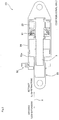
- An electric actuator 101 illustrated in Fig. 3 includes a cylinder body 84; a screw shaft 3 provided in the cylinder body 84 and rotated by an electric motor 23; and a piston rod 83 into which a screw shaft 3 is screwed. Further, a mechanical brake 81 is provided in the cylinder body 84. A side face of an end portion of the cylinder body 84 is provided with a limit switch 82.
- the electric motor 23 is activated to cause the piston rod 83 to move linearly in an advancing direction (leg-extending direction) or a retracting direction (leg-retracting direction) in accordance with rotation of the piston rod 83.
- the piston rod 83 moves in the leg-extending direction to cause a piston part 83a of the piston rod 83 to hit the limit switch 82.
- the electric motor 23 stops and the mechanical brake 81 is activated.
- the piston rod 83 is thus arrested and locked at a leg-extending position (stretched position). According to the electric actuator 101, no hydraulic pressure is utilized for driving the piston rod 83. This allows elimination of the hydraulic system which has been traditionally indispensable, thus realizing a lighter aircraft.
- EP1795987 which is regarded as being the closest prior art and discloses the preamble of claim 1.
- an object of the present invention is to provide an electric actuator which drives a piston rod by an electric motor via a screw shaft, which electric actuator is capable of reducing an external force or impact acting on the screw shaft when the piston rod is at the stretched position.
- the present inventors found that the above problem is solved by locking the piston rod with a fluid stored in the cylinder body, thus reducing the external force or impact acting on the screw shaft, when the piston rod is at the stretched position.
- the present invention is completed based on this finding.
- the present invention is disclosed in claim 1 and concerns an electric actuator comprising :
- the piston part of the advancing piston closes the first port to block the cylinder chamber connecting passage. This causes the head-side cylinder chamber of the cylinder body to seal the fluid therein.
- the electric actuator is capable of distributing an external force or impact in the liquid, the external force or impact acting in the retracting direction of the piston rod when the piston rod is at the stretched position. This reduces such forces as an impact acting on the screw shaft.
- a compact and lightweight electric actuator is achieved, compared to a known electric actuator.
- the present invention is provided with a nut into which the screw shaft is screwed, and an elastic member disposed between the nut and the piston part.
- the external force or impact is absorbed by the elastic member, preventing the external force or impact from acting directly on the screw shaft due to the rigidity of the fluid, thus receiving the external force or impact with the entire cylinder body.
- the present invention is preferably provided with a reservoir which is fixed to a side portion of the cylinder, and whose one chamber storing a fluid therein is connected to the rod-side cylinder chamber.
- the reservoir is capable of absorbing differential thermal expansion caused by the temperature of the fluid (high/low temperature), in addition to accumulating pressure of the fluid. This prevents unbalanced movement of the piston rod.
- the present invention is preferably provided with a first check valve whose forward direction is from the other chamber of the reservoir to the one chamber of the reservoir.
- the structure prevents vacuumization of the rod-side cylinder chamber due to an external force or impact acting on the piston rod, the rod-side cylinder chamber sealing the fluid therein.
- connection valve which connects the head-side cylinder chamber and the one chamber of the reservoir.
- connection valve when the cylinder chamber connecting passage connecting the first port and the second port is clogged, the connection valve is activated. This allows connection between the head-side cylinder chamber and the rod-side cylinder chamber of the cylinder body via the one chamber of the reservoir. This ensures linear movement of the piston rod.
- the present invention is preferably provided with a second check valve provided to the piston part of the piston rod.
- a forward direction of the second check valve is from the rod-side cylinder chamber to the head-side cylinder chamber.
- the structure prevents vacuumization of the head-side cylinder chamber sealing the fluid therein due to the external force or impact acting on the piston rod.
- the present invention is preferably provided with a relief valve which is provided to the piston part of the piston rod, and which connects the head-side cylinder chamber and the rod-side cylinder chamber when the pressure in the head-side cylinder chamber comes to be a predetermined value or more.
- the structure allows the fluid in the head-side cylinder chamber to escape to the rod-side cylinder chamber when the external force or impact acting on the piston rod is greater than assumed, or thermal expansion of the fluid is greater than assumed due to increased temperature of the fluid in the head-side cylinder chamber. This prevents excess rise of the fluid pressure in the head-side cylinder chamber.
- An actuator described below is for lifting a leg of a small aircraft; however, it is also employable as an actuator for lifting a leg of a medium or large aircraft.
- the present electric actuator is also employable as an actuator for locking a door (opening/closing a door) or the like of an aircraft.
- the present electric actuator is applicable to a machine other than aircraft.
- oil is employed as the fluid to be stored in the electric actuator of the present invention; however, a liquid other than oil, or a gas such as air may be employed as the fluid. Note that the following embodiment is described as an example where oil is employed as the fluid.
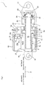
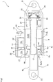
- Figs. 1 and 2 are schematic cross sectional views each illustrating an electric actuator 1 according to an embodiment of the present invention.
- Fig. 1 illustrates the electric actuator 1 with a piston rod 4 at a withdrawal position (retracted position).
- Fig. 2 illustrates the electric actuator 1 with the piston rod 4 at a stretched position (advanced position).
- the electric actuator 1 includes: a cylinder body 2 which stores oil therein; an electric motor 23, an electromagnetic brake 24, a screw shaft 3, and a piston rod 4, provided in the cylinder body 2; and a reservoir 12 integrally fixed to (integrally formed with) the cylinder body 2 at a side portion thereof.
- the cylinder body 2 has a cylindrical shape, and includes a cylinder chamber 5, a motor chamber 26, and a brake chamber 28.
- the cylinder chamber 5 is formed to a side of the cylinder body 2, to which side a leg of an aircraft is mounted.
- the motor chamber 26 and the brake chamber 28 are formed to a fuselage side of the cylinder body 2.
- an attach member 21 which attaches the cylinder body 2 to the fuselage.
- the leg includes a wheel and an arm of the wheel of the aircraft.
- the cylinder chamber 5 is separated into a cylinder chamber 5a on the rod side (hereinafter, rod-side cylinder chamber), and the cylinder chamber 5b on the head side (hereinafter, head-side cylinder chamber), by a later-described piston part 4a of the piston rod 4.
- the rod-side cylinder chamber 5a is located in a direction in which the leg of the aircraft is attached; i.e., a direction in which the piston rod 4 advances.
- the head-side cylinder chamber 5b is located in a direction in which the motor chamber 26 is provided; i.e., in a direction in which the piston rod 4 retracts.
- An inner face 8a of the rod-side cylinder chamber 5a is provided with a first port 6 and a third port 27.
- the third port 27 is provided to an end portion of the inner face 8a of the rod-side cylinder chamber 5a, which end portion is located towards a direction in which the piston rod 4 advances.
- the first port 6 is provided to an end portion of the inner face 8a of the rod-side cylinder 5a, which end portion is located more towards a direction in which the piston rod 4 retracts than the third port 27 is.
- the inner face 8b of the head-side cylinder chamber 5b is provided with a second port 7.
- the second port 7 is provided to an end portion of an inner face 8b of the head-side cylinder chamber 5b, which end portion is located towards the direction in which the piston rod 4 retracts.
- a side portion of the cylinder body 2 is provided with a cylinder chamber connecting passage 9 which connects the first port 6 and the second port 7.
- the cylinder chamber connecting passage 9 is a linear passage formed in the same direction as an X-direction in which the piston rod 4 moves linearly.
- the cylinder chamber connecting passage 9 is not limited to a linear passage, as long as it connects the first port 6 and the second port 7. Being a linear passage extending in the X-direction, the cylinder chamber connecting passage 9 connects the first port 6 and the second port 7 at the shortest distance. This further prevents the cylinder chamber connecting passage 9 from clogging.
- the electric motor 23 is for rotating the later-described screw shaft 3.
- the electric motor 23 is provided to the motor chamber 26.
- An encoder (not-illustrated) is built into the electric motor 23.
- the electric motor 23 can be halted at any position by a pulse signal from the encoder.
- a necessary number of limit switches 82 illustrated in Fig. 3 may be provided to the cylinder body 2 or the like, each of the limit switches 82 being set to operate at a position that the piston rod 4 is intended to be stopped, and the electric motor 23 may be halted by a signal from any one of the limit switches 82.
- the electromagnetic brake 24 is a parking brake for arresting the rotation of the screw shaft 3.
- the electromagnetic brake 24 is provided to the brake chamber 28 formed adjacent to the motor chamber 26. Due to the electromagnetic brake 24, the piston rod 4 is completely prevented from moving in an advancing side (leg-extending side) due to its own weight or an empty weight of the leg of the aircraft when the piston rod 4 is at the withdrawal position (retracted position). Note that the braking performance (brake performance) of the electromagnetic brake 24 is required to merely arrest movement of the piston rod 4 in the advancing side (leg-extending side) caused by the empty weight of the piston rod 4 as described above. Thus, no further function is required of the electromagnetic brake 24. Further, the electromagnetic brake 24 includes a manual brake release lever 25.
- Attached to the electric motor 23 is a screw shaft 3.
- the screw shaft 3 is provided in the cylinder chamber 5 and the motor chamber 26 in such a manner that a threaded portion of the screw shaft is present in the cylinder chamber 5.
- the cylinder chamber 5 and the motor chamber 26 are sealed.
- the seal is merely for preventing pressure at the time of impact from acting directly on the motor chamber 26 from the cylinder chamber 5.
- the seal is not indispensable.
- a wet-running motor is employed as the electric motor 23 for the purpose of its cooling.
- the screw shaft 3 is screwed into the nut 10. The electric motor 23 rotates the screw shaft 3 to cause the nut 10 to move linearly.
- the piston rod 4 is provided in the cylinder chamber 5.
- the piston rod 4 includes a rod part 4b and a piston part 4a.
- the rod part 4b is provided at its one end with an attach member 22 to which the leg of the aircraft is attached.
- the piston part 4a moves linearly (slide) along the inner faces 8a and 8b of the cylinder chamber 5.
- the rod part 4b is a hollow cylinder, and a screw shaft 3 is inserted therein.
- a second check valve 16 and a relief valve 17 are provided inside the piston part 4a.
- a forward direction of the second check valve 16 is a direction from the rod-side cylinder chamber 5a to the head-side cylinder chamber 5b of the cylinder chamber 5.
- the relief valve 17 connects the head-side cylinder chamber 5b and the rod-side cylinder chamber 5a when the hydraulic pressure in the head-side cylinder chamber 5b comes to be a predetermined value or more.
- a ring protrusion 4c is for ensuring a gap between a bottom face of the rod-side cylinder chamber 5a and the end face of the piston part 4a to ensure operations of the second check valve 16 and the relief valve 17, when the piston rod 4 is at the stretched position (advanced position) (see Fig. 2 ).
- a ring engaging member 4d is provided on a side of the piston part 4a towards which side the piston rod 4 retracts. The engaging member 4d engages with the nut 10 when the piston rod 4 retracts (withdraws).
- a disc spring 11 (elastic member).
- the elastic member to be provided between the piston part 4a and the nut 10 is not limited to the disc spring 11:
- the elastic member may be a rubber ring having a predetermined thickness.
- the reservoir 12 is integrally formed with the cylinder body 2 at a side thereof, the side located towards a direction in which the piston rod 4 advances.
- the reservoir 12 is separated into a chamber 12a and a chamber 12b by a piston 15.
- the chamber 12a stores oil therein
- the chamber 12b is provided with a coil spring 13 therein (the chamber 12b stores therein the coil spring 13 and air).
- the chamber 12a of the reservoir 12 and the rod-side cylinder chamber 5a are connected by the third port 27.
- a first check valve 14 therein whose forward direction is from the chamber 12b to the chamber 12a.
- the coil spring 13 is not indispensable.
- the coil spring 13 is for emergency use, to release brake and force the oil to flow.
- connection valve 18 is a two-position two-port electromagnetic valve having a block position for blocking the passages 19 and 20, and a connect position for connecting the passage 19 and the passage 20.
- connection valve 18 is an electromagnetic valve in the present embodiment, it may be a hydraulic pilot valve or a pneumatic pilot valve.
- the connection valve 18 is provided to the cylinder body 2 or a side portion of the reservoir 12, or the like.
- the electromagnetic brake 24 is released and the electric motor 23 is driven. This rotates the screw shaft 3, causing the piston rod 4 to advance with the nut 10.
- the oil flows from the rod-side cylinder chamber 5a to the head-side cylinder chamber 5b of the cylinder body 2 through the cylinder chamber connecting passage 9.
- the piston part 4a of the piston rod 4 closes the first port 6.
- connection valve 18 When the control unit of the aircraft gives a command to retract the leg, the connection valve 18 is excited, the electromagnetic brake 24 is released, and the electric motor 23 is driven.
- the connection valve 18 is excited to connect the chamber 12a of the reservoir 12 with the head-side cylinder chamber 5b.
- the electric motor 23 rotates the screw shaft 3, causing the piston rod 4 to retract with the nut 10.
- the oil flows from the head-side cylinder chamber 5b to the chamber 12a of the reservoir 12 through the passages 19 and 20.
- the energization of the connection valve 18 stops, and the oil flows from the head-side cylinder chamber 5b to the rod-side cylinder 5a thereafter through the cylinder chamber connecting passage 9.
- the electric motor 23 When the piston rod 4 has reached the withdrawal position (retracted position) (determined by a signal from the encoder), the electric motor 23 is halted, and the electromagnetic brake 24 is activated.
- the piston part 4a of the advancing piston rod 4 closes the first port 6, blocking the cylinder chamber connecting passage 9, as described above.
- This causes the head-side cylinder chamber 5b of the cylinder body 2 to seal the oil therein.
- the electric actuator 1 is capable of distributing an external force or impact in the oil, the external force or impact acting in the retracting direction of the piston rod 4 at the stretched position. This reduces such forces as an impact acting on the screw shaft 3. As a result, an actuator smaller and lighter than a conventional one is realized.
- the external force or impact is absorbed by the disc spring 11 provided between the piston part 4a and the nut 10, preventing the external force or impact from acting directly on the screw shaft 3 due to the rigidity of the oil, thus receiving the external force or impact with the entire cylinder body 2.
- the reservoir 12 including the coil spring 13 is able to absorb differential thermal expansion caused by the temperature (high/low temperature) of the oil. This prevents unbalanced movement of the piston rod 4.
- the rod-side cylinder chamber 5a of the cylinder body 2 tends to be vacuumized, the rod-side cylinder chamber 5a sealing the oil therein.
- the first check valve 14 provided to the piston 15 prevents vacuumization of the rod-side cylinder chamber 5a.
- the head-side cylinder chamber 5b of the cylinder body 2 tends to be vacuumized.
- the oil is flown from the rod-side cylinder chamber 5a to the head-side cylinder 5b by the second check valve 16 provided to the piston rod 4a. This prevents vacuumization of the head-side cylinder chamber 5b.
- the relief valve 17 provided to the piston part 4a allows the oil in the head-side cylinder chamber 5b to escape to the rod-side cylinder chamber 5a when the external force or impact acting in the retracting direction of the piston rod 4 is greater than assumed, or thermal expansion of the oil is greater than assumed due to increased temperature of the oil in the head-side cylinder chamber 5b. This prevents excess rise in the hydraulic pressure in the head-side cylinder chamber 5b.
- connection valve 18 is activated to connect the head-side cylinder chamber 5b and the rod-side cylinder chamber 5a of the cylinder body 2 via the chamber 12a of the reservoir 12, thus ensuring linear movement of the piston rod 4.
Landscapes
- Engineering & Computer Science (AREA)
- Mechanical Engineering (AREA)
- Aviation & Aerospace Engineering (AREA)
- Actuator (AREA)
- Transmission Devices (AREA)
- Connection Of Motors, Electrical Generators, Mechanical Devices, And The Like (AREA)
Claims (6)
- Actionneur électrique comprenant :un corps de cylindre (2) qui stocke à l'intérieur de ce dernier, un fluide ;un arbre à vis (3) qui est prévu dans le corps de cylindre et tourne grâce à un moteur électrique ;une tige de piston (4) qui se déplace de manière linéaire selon la rotation de l'arbre à vis ;un premier orifice (6) formé sur une face interne d'une chambre de cylindre du côté de la tige du corps de cylindre, laquelle chambre de cylindre (5) est positionnée dans une direction dans laquelle la tige de piston avance ;un second orifice (7) formé sur une face interne d'une chambre de cylindre du côté de la tête du corps de cylindre, laquelle chambre de cylindre est positionnée dans une direction dans laquelle la tige de piston recule ; etun passage de raccordement de chambre de cylindre (2) raccordant le premier orifice et le second orifice,caractérisé en ce que la partie de piston de la tige de piston ferme le premier orifice lorsque la tige de piston avance, l'actionneur électrique comprend en outre :un écrou (10) dans lequel l'arbre à vis (3) est vissé ; etun élément élastique (11) prévu entre l'écrou et la partie de piston.
- Actionneur électrique selon la revendication 1, comprenant en outre un réservoir (12) qui est fixé sur une partie latérale du corps de cylindre, et dont une chambre (12a) stockant un fluide à l'intérieur de ce dernier, est raccordée à la chambre de cylindre du côté de la tige.
- Actionneur électrique selon la revendication 2, caractérisé en ce qu'il comprend une première valve anti-retour (14) dont la direction avant va de l'autre chambre du réservoir à la première chambre du réservoir.
- Actionneur électrique selon la revendication 2 ou 3, caractérisé en ce qu'il comprend une valve de raccordement (18) qui raccorde la chambre de cylindre du côté de la tête et la première chambre du réservoir.
- Actionneur électrique selon l'une quelconque des revendications 2 à 4, caractérisé en ce qu'il comprend une seconde valve anti-retour (16) qui est prévue sur la partie de piston de la tige de piston, et dont la direction avant va de la chambre de cylindre du côté de la tige jusqu'à la chambre de cylindre du côté de la tête.
- Actionneur électrique selon l'une quelconque des revendications 1 à 5, caractérisé en ce qu'il comprend une valve de décharge (17) qui est prévue sur la partie de piston de la tige de piston, et qui raccorde la chambre de cylindre du côté de la tête et la chambre de cylindre du côté de la tige lorsque la pression dans la chambre de cylindre du côté de la tête atteint une valeur prédéterminée ou la dépasse.
Applications Claiming Priority (1)
| Application Number | Priority Date | Filing Date | Title |
|---|---|---|---|
| JP2008306517A JP2010127456A (ja) | 2008-12-01 | 2008-12-01 | 電動アクチュエータ |
Publications (3)
| Publication Number | Publication Date |
|---|---|
| EP2192041A2 EP2192041A2 (fr) | 2010-06-02 |
| EP2192041A3 EP2192041A3 (fr) | 2017-06-07 |
| EP2192041B1 true EP2192041B1 (fr) | 2019-07-10 |
Family
ID=41821902
Family Applications (1)
| Application Number | Title | Priority Date | Filing Date |
|---|---|---|---|
| EP09177638.5A Not-in-force EP2192041B1 (fr) | 2008-12-01 | 2009-12-01 | Actionneur électrique pour train d'atterrissage d'aéronef |
Country Status (3)
| Country | Link |
|---|---|
| US (1) | US8474339B2 (fr) |
| EP (1) | EP2192041B1 (fr) |
| JP (1) | JP2010127456A (fr) |
Families Citing this family (12)
| Publication number | Priority date | Publication date | Assignee | Title |
|---|---|---|---|---|
| FR2946618B1 (fr) * | 2009-06-11 | 2011-07-29 | Messier Bugatti | Actionneur a fonctionnement mecanique et amortissement hydraulique. |
| WO2012142188A2 (fr) | 2011-04-11 | 2012-10-18 | Milwaukee Electric Tool Corporation | Dispositif de poinçon éjecteur hydraulique à main |
| US9016317B2 (en) | 2012-07-31 | 2015-04-28 | Milwaukee Electric Tool Corporation | Multi-operational valve |
| FR2998263B1 (fr) * | 2012-11-22 | 2015-07-03 | Messier Bugatti Dowty | Actionneur mecanique avec dispositif d amortissement hydraulique |
| CN104859626B (zh) * | 2015-05-28 | 2017-07-14 | 西北工业大学 | 一种飞机电静液刹车作动器 |
| DE102017111032A1 (de) * | 2017-05-20 | 2018-11-22 | Inventus Engineering Gmbh | Vorrichtung mit einem steuerbaren Drehdämpfer |
| CN109519449B (zh) * | 2018-11-28 | 2020-07-14 | 北京精密机电控制设备研究所 | 一种集成式机电伺服机构 |
| JP7315168B2 (ja) * | 2019-07-22 | 2023-07-26 | 株式会社Zmp | 流体圧機器及び動作装置 |
| US11066153B2 (en) | 2019-09-20 | 2021-07-20 | Goodrich Corporation | Electric nose landing gear architecture |
| US11092175B1 (en) * | 2020-03-23 | 2021-08-17 | The Boeing Company | Dual-independent hybrid actuator system |
| US20230063097A1 (en) * | 2021-08-27 | 2023-03-02 | Viettel Group | Electrical driving mechanism for sonic flying devices |
| CN115107978B (zh) * | 2022-07-29 | 2023-08-11 | 广东逸动科技有限公司 | 伸缩装置、推进器以及船舶 |
Family Cites Families (8)
| Publication number | Priority date | Publication date | Assignee | Title |
|---|---|---|---|---|
| US1730797A (en) * | 1928-05-11 | 1929-10-08 | Quincy Elevator Gate Company | Electric-motor speed control |
| US3823758A (en) * | 1970-12-03 | 1974-07-16 | Allen Electric Equipment Co | Actuator assembly |
| JP3671198B2 (ja) | 1997-06-13 | 2005-07-13 | ナブテスコ株式会社 | 航空機用脚昇降装置 |
| JPH11272332A (ja) * | 1998-03-23 | 1999-10-08 | Ishikawajima Harima Heavy Ind Co Ltd | 位置決めシリンダ装置 |
| JP4273447B2 (ja) * | 2001-08-07 | 2009-06-03 | 新東工業株式会社 | 電動プレス装置 |
| JP4443391B2 (ja) * | 2004-11-26 | 2010-03-31 | カヤバ工業株式会社 | シリンダ装置 |
| JP4890845B2 (ja) * | 2005-12-08 | 2012-03-07 | ナブテスコ株式会社 | アクチュエータ機構 |
| FR2946618B1 (fr) * | 2009-06-11 | 2011-07-29 | Messier Bugatti | Actionneur a fonctionnement mecanique et amortissement hydraulique. |
-
2008
- 2008-12-01 JP JP2008306517A patent/JP2010127456A/ja active Pending
-
2009
- 2009-12-01 EP EP09177638.5A patent/EP2192041B1/fr not_active Not-in-force
- 2009-12-01 US US12/628,731 patent/US8474339B2/en active Active
Non-Patent Citations (1)
| Title |
|---|
| None * |
Also Published As
| Publication number | Publication date |
|---|---|
| JP2010127456A (ja) | 2010-06-10 |
| US8474339B2 (en) | 2013-07-02 |
| EP2192041A3 (fr) | 2017-06-07 |
| EP2192041A2 (fr) | 2010-06-02 |
| US20100132350A1 (en) | 2010-06-03 |
Similar Documents
| Publication | Publication Date | Title |
|---|---|---|
| EP2192041B1 (fr) | Actionneur électrique pour train d'atterrissage d'aéronef | |
| EP2910466B1 (fr) | Cylindre de transfert électrique pour système de train d'atterrissage | |
| US8070095B2 (en) | Shrinking shock strut system for retractable landing gear | |
| US9969233B2 (en) | Mechanical actuator with a hydraulic damper device | |
| CN109268349B (zh) | 一种具有单端机械锁的双余度液压作动器 | |
| JP5306838B2 (ja) | 電動アクチュエータ | |
| US5908174A (en) | Automatic shrink shock strut for an aircraft landing gear | |
| EP2152987B1 (fr) | Mecanisme d'ouverture d'urgence de porte | |
| EP2951444B1 (fr) | Mécanisme de blocage pour bloquer un actionneur | |
| US2868482A (en) | Retractable landing gear | |
| US7967119B2 (en) | Telescopic member having an overridable internal abutment | |
| EP3926178A1 (fr) | Soupape de régulation de débit, procédé d'assemblage et système hydraulique | |
| CN110925262A (zh) | 一种双余度开锁作动装置 | |
| CN214092551U (zh) | 上位锁作动筒缓冲装置 | |
| CN112431817A (zh) | 控制作动筒运动速度的缓冲装置 | |
| CN110863796B (zh) | 一种密封段电动泄压方法及装置 | |
| CN112636528A (zh) | 多余度应急功能机电作动器 | |
| CN215043641U (zh) | 起落架任意位置液压收放系统 | |
| WO2022234027A1 (fr) | Système de freinage à antiblocage | |
| CN110748519A (zh) | 一种电液集成双向锁紧防爆液压缸 | |
| CN115978156A (zh) | 具备非相似能源应急伸出功能的重载收放机电作动器 |
Legal Events
| Date | Code | Title | Description |
|---|---|---|---|
| PUAI | Public reference made under article 153(3) epc to a published international application that has entered the european phase |
Free format text: ORIGINAL CODE: 0009012 |
|
| 17P | Request for examination filed |
Effective date: 20091201 |
|
| AK | Designated contracting states |
Kind code of ref document: A2 Designated state(s): AT BE BG CH CY CZ DE DK EE ES FI FR GB GR HR HU IE IS IT LI LT LU LV MC MK MT NL NO PL PT RO SE SI SK SM TR |
|
| AX | Request for extension of the european patent |
Extension state: AL BA RS |
|
| PUAL | Search report despatched |
Free format text: ORIGINAL CODE: 0009013 |
|
| AK | Designated contracting states |
Kind code of ref document: A3 Designated state(s): AT BE BG CH CY CZ DE DK EE ES FI FR GB GR HR HU IE IS IT LI LT LU LV MC MK MT NL NO PL PT RO SE SI SK SM TR |
|
| AX | Request for extension of the european patent |
Extension state: AL BA RS |
|
| RIC1 | Information provided on ipc code assigned before grant |
Ipc: B64C 25/24 20060101AFI20170428BHEP |
|
| PUAL | Search report despatched |
Free format text: ORIGINAL CODE: 0009013 |
|
| GRAP | Despatch of communication of intention to grant a patent |
Free format text: ORIGINAL CODE: EPIDOSNIGR1 |
|
| STAA | Information on the status of an ep patent application or granted ep patent |
Free format text: STATUS: GRANT OF PATENT IS INTENDED |
|
| INTG | Intention to grant announced |
Effective date: 20190301 |
|
| GRAS | Grant fee paid |
Free format text: ORIGINAL CODE: EPIDOSNIGR3 |
|
| GRAA | (expected) grant |
Free format text: ORIGINAL CODE: 0009210 |
|
| STAA | Information on the status of an ep patent application or granted ep patent |
Free format text: STATUS: THE PATENT HAS BEEN GRANTED |
|
| AK | Designated contracting states |
Kind code of ref document: B1 Designated state(s): AT BE BG CH CY CZ DE DK EE ES FI FR GB GR HR HU IE IS IT LI LT LU LV MC MK MT NL NO PL PT RO SE SI SK SM TR |
|
| REG | Reference to a national code |
Ref country code: GB Ref legal event code: FG4D |
|
| REG | Reference to a national code |
Ref country code: CH Ref legal event code: EP Ref country code: AT Ref legal event code: REF Ref document number: 1153310 Country of ref document: AT Kind code of ref document: T Effective date: 20190715 |
|
| REG | Reference to a national code |
Ref country code: DE Ref legal event code: R096 Ref document number: 602009059065 Country of ref document: DE |
|
| REG | Reference to a national code |
Ref country code: IE Ref legal event code: FG4D |
|
| REG | Reference to a national code |
Ref country code: NL Ref legal event code: MP Effective date: 20190710 |
|
| REG | Reference to a national code |
Ref country code: LT Ref legal event code: MG4D |
|
| REG | Reference to a national code |
Ref country code: AT Ref legal event code: MK05 Ref document number: 1153310 Country of ref document: AT Kind code of ref document: T Effective date: 20190710 |
|
| PG25 | Lapsed in a contracting state [announced via postgrant information from national office to epo] |
Ref country code: FI Free format text: LAPSE BECAUSE OF FAILURE TO SUBMIT A TRANSLATION OF THE DESCRIPTION OR TO PAY THE FEE WITHIN THE PRESCRIBED TIME-LIMIT Effective date: 20190710 Ref country code: SE Free format text: LAPSE BECAUSE OF FAILURE TO SUBMIT A TRANSLATION OF THE DESCRIPTION OR TO PAY THE FEE WITHIN THE PRESCRIBED TIME-LIMIT Effective date: 20190710 Ref country code: PT Free format text: LAPSE BECAUSE OF FAILURE TO SUBMIT A TRANSLATION OF THE DESCRIPTION OR TO PAY THE FEE WITHIN THE PRESCRIBED TIME-LIMIT Effective date: 20191111 Ref country code: LT Free format text: LAPSE BECAUSE OF FAILURE TO SUBMIT A TRANSLATION OF THE DESCRIPTION OR TO PAY THE FEE WITHIN THE PRESCRIBED TIME-LIMIT Effective date: 20190710 Ref country code: NL Free format text: LAPSE BECAUSE OF FAILURE TO SUBMIT A TRANSLATION OF THE DESCRIPTION OR TO PAY THE FEE WITHIN THE PRESCRIBED TIME-LIMIT Effective date: 20190710 Ref country code: HR Free format text: LAPSE BECAUSE OF FAILURE TO SUBMIT A TRANSLATION OF THE DESCRIPTION OR TO PAY THE FEE WITHIN THE PRESCRIBED TIME-LIMIT Effective date: 20190710 Ref country code: AT Free format text: LAPSE BECAUSE OF FAILURE TO SUBMIT A TRANSLATION OF THE DESCRIPTION OR TO PAY THE FEE WITHIN THE PRESCRIBED TIME-LIMIT Effective date: 20190710 Ref country code: NO Free format text: LAPSE BECAUSE OF FAILURE TO SUBMIT A TRANSLATION OF THE DESCRIPTION OR TO PAY THE FEE WITHIN THE PRESCRIBED TIME-LIMIT Effective date: 20191010 Ref country code: BG Free format text: LAPSE BECAUSE OF FAILURE TO SUBMIT A TRANSLATION OF THE DESCRIPTION OR TO PAY THE FEE WITHIN THE PRESCRIBED TIME-LIMIT Effective date: 20191010 |
|
| PG25 | Lapsed in a contracting state [announced via postgrant information from national office to epo] |
Ref country code: ES Free format text: LAPSE BECAUSE OF FAILURE TO SUBMIT A TRANSLATION OF THE DESCRIPTION OR TO PAY THE FEE WITHIN THE PRESCRIBED TIME-LIMIT Effective date: 20190710 Ref country code: LV Free format text: LAPSE BECAUSE OF FAILURE TO SUBMIT A TRANSLATION OF THE DESCRIPTION OR TO PAY THE FEE WITHIN THE PRESCRIBED TIME-LIMIT Effective date: 20190710 Ref country code: GR Free format text: LAPSE BECAUSE OF FAILURE TO SUBMIT A TRANSLATION OF THE DESCRIPTION OR TO PAY THE FEE WITHIN THE PRESCRIBED TIME-LIMIT Effective date: 20191011 Ref country code: IS Free format text: LAPSE BECAUSE OF FAILURE TO SUBMIT A TRANSLATION OF THE DESCRIPTION OR TO PAY THE FEE WITHIN THE PRESCRIBED TIME-LIMIT Effective date: 20191110 |
|
| PG25 | Lapsed in a contracting state [announced via postgrant information from national office to epo] |
Ref country code: TR Free format text: LAPSE BECAUSE OF FAILURE TO SUBMIT A TRANSLATION OF THE DESCRIPTION OR TO PAY THE FEE WITHIN THE PRESCRIBED TIME-LIMIT Effective date: 20190710 |
|
| PG25 | Lapsed in a contracting state [announced via postgrant information from national office to epo] |
Ref country code: IT Free format text: LAPSE BECAUSE OF FAILURE TO SUBMIT A TRANSLATION OF THE DESCRIPTION OR TO PAY THE FEE WITHIN THE PRESCRIBED TIME-LIMIT Effective date: 20190710 Ref country code: RO Free format text: LAPSE BECAUSE OF FAILURE TO SUBMIT A TRANSLATION OF THE DESCRIPTION OR TO PAY THE FEE WITHIN THE PRESCRIBED TIME-LIMIT Effective date: 20190710 Ref country code: PL Free format text: LAPSE BECAUSE OF FAILURE TO SUBMIT A TRANSLATION OF THE DESCRIPTION OR TO PAY THE FEE WITHIN THE PRESCRIBED TIME-LIMIT Effective date: 20190710 Ref country code: EE Free format text: LAPSE BECAUSE OF FAILURE TO SUBMIT A TRANSLATION OF THE DESCRIPTION OR TO PAY THE FEE WITHIN THE PRESCRIBED TIME-LIMIT Effective date: 20190710 Ref country code: DK Free format text: LAPSE BECAUSE OF FAILURE TO SUBMIT A TRANSLATION OF THE DESCRIPTION OR TO PAY THE FEE WITHIN THE PRESCRIBED TIME-LIMIT Effective date: 20190710 |
|
| PG25 | Lapsed in a contracting state [announced via postgrant information from national office to epo] |
Ref country code: CZ Free format text: LAPSE BECAUSE OF FAILURE TO SUBMIT A TRANSLATION OF THE DESCRIPTION OR TO PAY THE FEE WITHIN THE PRESCRIBED TIME-LIMIT Effective date: 20190710 Ref country code: SM Free format text: LAPSE BECAUSE OF FAILURE TO SUBMIT A TRANSLATION OF THE DESCRIPTION OR TO PAY THE FEE WITHIN THE PRESCRIBED TIME-LIMIT Effective date: 20190710 Ref country code: IS Free format text: LAPSE BECAUSE OF FAILURE TO SUBMIT A TRANSLATION OF THE DESCRIPTION OR TO PAY THE FEE WITHIN THE PRESCRIBED TIME-LIMIT Effective date: 20200224 Ref country code: SK Free format text: LAPSE BECAUSE OF FAILURE TO SUBMIT A TRANSLATION OF THE DESCRIPTION OR TO PAY THE FEE WITHIN THE PRESCRIBED TIME-LIMIT Effective date: 20190710 |
|
| REG | Reference to a national code |
Ref country code: DE Ref legal event code: R097 Ref document number: 602009059065 Country of ref document: DE |
|
| PLBE | No opposition filed within time limit |
Free format text: ORIGINAL CODE: 0009261 |
|
| STAA | Information on the status of an ep patent application or granted ep patent |
Free format text: STATUS: NO OPPOSITION FILED WITHIN TIME LIMIT |
|
| PG2D | Information on lapse in contracting state deleted |
Ref country code: IS |
|
| REG | Reference to a national code |
Ref country code: CH Ref legal event code: PL |
|
| 26N | No opposition filed |
Effective date: 20200603 |
|
| REG | Reference to a national code |
Ref country code: BE Ref legal event code: MM Effective date: 20191231 |
|
| PG25 | Lapsed in a contracting state [announced via postgrant information from national office to epo] |
Ref country code: MC Free format text: LAPSE BECAUSE OF FAILURE TO SUBMIT A TRANSLATION OF THE DESCRIPTION OR TO PAY THE FEE WITHIN THE PRESCRIBED TIME-LIMIT Effective date: 20190710 Ref country code: SI Free format text: LAPSE BECAUSE OF FAILURE TO SUBMIT A TRANSLATION OF THE DESCRIPTION OR TO PAY THE FEE WITHIN THE PRESCRIBED TIME-LIMIT Effective date: 20190710 |
|
| GBPC | Gb: european patent ceased through non-payment of renewal fee |
Effective date: 20191201 |
|
| PG25 | Lapsed in a contracting state [announced via postgrant information from national office to epo] |
Ref country code: GB Free format text: LAPSE BECAUSE OF NON-PAYMENT OF DUE FEES Effective date: 20191201 Ref country code: IE Free format text: LAPSE BECAUSE OF NON-PAYMENT OF DUE FEES Effective date: 20191201 Ref country code: LU Free format text: LAPSE BECAUSE OF NON-PAYMENT OF DUE FEES Effective date: 20191201 |
|
| PG25 | Lapsed in a contracting state [announced via postgrant information from national office to epo] |
Ref country code: CH Free format text: LAPSE BECAUSE OF NON-PAYMENT OF DUE FEES Effective date: 20191231 Ref country code: LI Free format text: LAPSE BECAUSE OF NON-PAYMENT OF DUE FEES Effective date: 20191231 Ref country code: BE Free format text: LAPSE BECAUSE OF NON-PAYMENT OF DUE FEES Effective date: 20191231 |
|
| PGFP | Annual fee paid to national office [announced via postgrant information from national office to epo] |
Ref country code: DE Payment date: 20201211 Year of fee payment: 12 Ref country code: FR Payment date: 20201223 Year of fee payment: 12 |
|
| PG25 | Lapsed in a contracting state [announced via postgrant information from national office to epo] |
Ref country code: CY Free format text: LAPSE BECAUSE OF FAILURE TO SUBMIT A TRANSLATION OF THE DESCRIPTION OR TO PAY THE FEE WITHIN THE PRESCRIBED TIME-LIMIT Effective date: 20190710 |
|
| PG25 | Lapsed in a contracting state [announced via postgrant information from national office to epo] |
Ref country code: HU Free format text: LAPSE BECAUSE OF FAILURE TO SUBMIT A TRANSLATION OF THE DESCRIPTION OR TO PAY THE FEE WITHIN THE PRESCRIBED TIME-LIMIT; INVALID AB INITIO Effective date: 20091201 Ref country code: MT Free format text: LAPSE BECAUSE OF FAILURE TO SUBMIT A TRANSLATION OF THE DESCRIPTION OR TO PAY THE FEE WITHIN THE PRESCRIBED TIME-LIMIT Effective date: 20190710 |
|
| PG25 | Lapsed in a contracting state [announced via postgrant information from national office to epo] |
Ref country code: MK Free format text: LAPSE BECAUSE OF FAILURE TO SUBMIT A TRANSLATION OF THE DESCRIPTION OR TO PAY THE FEE WITHIN THE PRESCRIBED TIME-LIMIT Effective date: 20190710 |
|
| REG | Reference to a national code |
Ref country code: DE Ref legal event code: R119 Ref document number: 602009059065 Country of ref document: DE |
|
| PG25 | Lapsed in a contracting state [announced via postgrant information from national office to epo] |
Ref country code: DE Free format text: LAPSE BECAUSE OF NON-PAYMENT OF DUE FEES Effective date: 20220701 |
|
| PG25 | Lapsed in a contracting state [announced via postgrant information from national office to epo] |
Ref country code: FR Free format text: LAPSE BECAUSE OF NON-PAYMENT OF DUE FEES Effective date: 20211231 |