EP2191181B1 - Apparatus and methods for manual override operation of a linear actuator - Google Patents
Apparatus and methods for manual override operation of a linear actuator Download PDFInfo
- Publication number
- EP2191181B1 EP2191181B1 EP08831861.3A EP08831861A EP2191181B1 EP 2191181 B1 EP2191181 B1 EP 2191181B1 EP 08831861 A EP08831861 A EP 08831861A EP 2191181 B1 EP2191181 B1 EP 2191181B1
- Authority
- EP
- European Patent Office
- Prior art keywords
- stem
- actuator
- valve
- collar
- base
- Prior art date
- Legal status (The legal status is an assumption and is not a legal conclusion. Google has not performed a legal analysis and makes no representation as to the accuracy of the status listed.)
- Active
Links
Images


Classifications
-
- F—MECHANICAL ENGINEERING; LIGHTING; HEATING; WEAPONS; BLASTING
- F16—ENGINEERING ELEMENTS AND UNITS; GENERAL MEASURES FOR PRODUCING AND MAINTAINING EFFECTIVE FUNCTIONING OF MACHINES OR INSTALLATIONS; THERMAL INSULATION IN GENERAL
- F16K—VALVES; TAPS; COCKS; ACTUATING-FLOATS; DEVICES FOR VENTING OR AERATING
- F16K31/00—Actuating devices; Operating means; Releasing devices
- F16K31/44—Mechanical actuating means
- F16K31/50—Mechanical actuating means with screw-spindle or internally threaded actuating means
- F16K31/508—Mechanical actuating means with screw-spindle or internally threaded actuating means the actuating element being rotatable, non-rising, and driving a non-rotatable axially-sliding element
-
- F—MECHANICAL ENGINEERING; LIGHTING; HEATING; WEAPONS; BLASTING
- F16—ENGINEERING ELEMENTS AND UNITS; GENERAL MEASURES FOR PRODUCING AND MAINTAINING EFFECTIVE FUNCTIONING OF MACHINES OR INSTALLATIONS; THERMAL INSULATION IN GENERAL
- F16K—VALVES; TAPS; COCKS; ACTUATING-FLOATS; DEVICES FOR VENTING OR AERATING
- F16K31/00—Actuating devices; Operating means; Releasing devices
- F16K31/12—Actuating devices; Operating means; Releasing devices actuated by fluid
- F16K31/126—Actuating devices; Operating means; Releasing devices actuated by fluid the fluid acting on a diaphragm, bellows, or the like
- F16K31/1262—Actuating devices; Operating means; Releasing devices actuated by fluid the fluid acting on a diaphragm, bellows, or the like one side of the diaphragm being spring loaded
-
- Y—GENERAL TAGGING OF NEW TECHNOLOGICAL DEVELOPMENTS; GENERAL TAGGING OF CROSS-SECTIONAL TECHNOLOGIES SPANNING OVER SEVERAL SECTIONS OF THE IPC; TECHNICAL SUBJECTS COVERED BY FORMER USPC CROSS-REFERENCE ART COLLECTIONS [XRACs] AND DIGESTS
- Y10—TECHNICAL SUBJECTS COVERED BY FORMER USPC
- Y10T—TECHNICAL SUBJECTS COVERED BY FORMER US CLASSIFICATION
- Y10T137/00—Fluid handling
- Y10T137/0318—Processes
-
- Y—GENERAL TAGGING OF NEW TECHNOLOGICAL DEVELOPMENTS; GENERAL TAGGING OF CROSS-SECTIONAL TECHNOLOGIES SPANNING OVER SEVERAL SECTIONS OF THE IPC; TECHNICAL SUBJECTS COVERED BY FORMER USPC CROSS-REFERENCE ART COLLECTIONS [XRACs] AND DIGESTS
- Y10—TECHNICAL SUBJECTS COVERED BY FORMER USPC
- Y10T—TECHNICAL SUBJECTS COVERED BY FORMER US CLASSIFICATION
- Y10T74/00—Machine element or mechanism
- Y10T74/18—Mechanical movements
- Y10T74/18568—Reciprocating or oscillating to or from alternating rotary
- Y10T74/18576—Reciprocating or oscillating to or from alternating rotary including screw and nut
- Y10T74/18704—Means to selectively lock or retard screw or nut
-
- Y—GENERAL TAGGING OF NEW TECHNOLOGICAL DEVELOPMENTS; GENERAL TAGGING OF CROSS-SECTIONAL TECHNOLOGIES SPANNING OVER SEVERAL SECTIONS OF THE IPC; TECHNICAL SUBJECTS COVERED BY FORMER USPC CROSS-REFERENCE ART COLLECTIONS [XRACs] AND DIGESTS
- Y10—TECHNICAL SUBJECTS COVERED BY FORMER USPC
- Y10T—TECHNICAL SUBJECTS COVERED BY FORMER US CLASSIFICATION
- Y10T74/00—Machine element or mechanism
- Y10T74/18—Mechanical movements
- Y10T74/18568—Reciprocating or oscillating to or from alternating rotary
- Y10T74/18576—Reciprocating or oscillating to or from alternating rotary including screw and nut
- Y10T74/18752—Manually driven
Definitions
- This disclosure relates generally to control valves and, more particularly, to apparatus and methods to manually override operation of a linear actuator.
- Actuators automate control valves by supplying force and motion to open or close a valve.
- Pneumatic actuators are used to operate control valves such as, for example, linear valves, rotary valves, etc.
- Linear valves such as gate, globe, diaphragm, pinch, and angle valves typically have a valve stem (e.g., a sliding stem) that drives a flow control member (e.g., a plug) between an open position and a closed position.
- Rotary valves such as butterfly valves, ball valves, disk valves, etc. typically have a valve shaft that drives a flow control member between an open position and a closed position.
- an actuator stem operatively couples a linear valve stem or a rotary valve shaft to the actuator (e.g., a pneumatic actuator, hydraulic actuator, etc.).
- a controller may cause an actuator to position a valve stem or shaft and, thus, a flow control member to a desired position to regulate the fluid flowing through a valve.
- the flow control member is typically configured to engage an annular or circumferential seal that encircles the flow path through the valve to prevent the flow of fluid (e.g., in one or both directions) through the valve.
- a desired position e.g., a closed position
- known manual override mechanisms for control valves permit manual operation of a valve and do not require an outside power source to move the flow control member of the valve to a desired position.
- these known manual override mechanisms typically use a hand wheel, a chain wheel, a lever, a declutchable mechanism, or a combination thereof, to drive a series of gears (e.g., a worm drive gearbox, etc.) providing a reduction that results in a higher output torque compared to an input (manual) torque provided by a person.
- a series of gears e.g., a worm drive gearbox, etc.
- Some known manual override mechanisms use a worm drive gearbox in which a self-locking worm and worm gear drive holds the valve in a desired position.
- this configuration usually requires aligning a hole in a manual override stem with a hole in an actuator stem and sliding a pin therethrough to engage the manual override mechanism. During emergency situations, this process can be time consuming and unacceptable.
- Other known applications utilize a declutchable worm drive gear box that involves manually engaging a lever to enable manual operation of a valve via a hand wheel.
- worm drive gearboxes are relatively expensive and involve complex assemblies with the actuator.
- most known manual override mechanisms using a worm drive gearbox are only available as a factory installed option and cannot be retrofitted to existing valves in the field.
- Another known example manual override mechanism provides a hand wheel and screw combination that is mounted directly to an actuator to manually operate a valve.
- this known configuration limits operation of some valves in one direction and, thus, once these valves are manually operated, the override mechanism cannot be used to operate the valve in the other or opposite direction.
- Patent Documents EP 0 655 574 A and FR 1 300 618 A are considered to be the closest prior art and relates to a manual override operation of a linear actuator, as described in preamble of the independent claims.
- the example manual override apparatus described herein can be used to selectively engage, for example, a valve actuator to enable control of the actuator to position a flow control member of a valve at any position between a fully open position in which the flow of fluid through the valve is permitted and a fully closed position in which the flow of fluid through the valve is restricted or prevented.
- the example manual override apparatus discussed herein can be applied to pneumatically operated control valves having a linear actuator such as, for example, control valves, throttling valves, on/off valves, etc.
- the example manual override apparatus is particularly advantageous in use with dual actuated actuators (i.e., in which pressurized fluid is used to open and close the valve) and with fluid-to-open or fail-to-close actuated valves (i.e., in which a spring biases the valve in the closed position).
- dual actuated actuators i.e., in which pressurized fluid is used to open and close the valve
- fluid-to-open or fail-to-close actuated valves i.e., in which a spring biases the valve in the closed position
- the example manual override apparatus described herein may be provided as a factory installed option or alternatively, can retrofit existing control valves in the field.
- a control valve assembly includes a valve body that houses internal trim parts and an actuator to provide the power to operate the valve.
- the valve body is the main pressure boundary of the valve housing that provides the fluid flow passageway, the pipe connecting ends, and supports the seating surfaces for a valve flow control member (e.g., a plug).
- the internal trim parts are internal components of a valve that control the flow of the fluid through the valve.
- the trim can include a flow control member, a seat ring, a cage, a valve stem, and a stem pin.
- Pneumatic actuators such as piston actuators and diaphragm actuators
- Example piston and diaphragm actuated control valves 100 and 101 are shown and described below in connection with FIGS. 1A and 1B , respectively.
- the example described in connection with the manual override apparatus is not limited to the example illustrations of FIG. 1A and 1B and may be used with various types of valves such as, for example, a sliding stem valve (e.g., a gate valve, a globe valve, etc.) and a rotary valve (e.g., a ball valve, a disk valve, a butterfly valve, etc.) that are operated by a linear actuator such as, for example, the actuator 142 of FIG. 1B .
- a sliding stem valve e.g., a gate valve, a globe valve, etc.
- a rotary valve e.g., a ball valve, a disk valve, a butterfly valve, etc.
- the control valve 100 shown in FIG. 1A includes a valve body 102 connected to a bonnet 104.
- the bonnet 104 houses an actuator stem 106 that is coupled to a valve stem 108 at a lower end 110 of the actuator stem 106.
- the valve stem 108 passes through the bonnet 104 and into the valve body 102.
- a valve plug 112 is coupled to a lower end 114 of the valve stem 108.
- the valve stem 108 and the valve plug 112 may be formed as a single piece, or may be formed in separate pieces for connection by common fastening methods.
- the valve plug 112 includes a seating surface 116 that cooperates with a valve seat 118 of an orifice 120 to control the port area through which fluid may flow from an inlet passage 122 to an outlet passage 124.
- the flow rate permitted through the control valve 100 is controlled by the position of the valve stem 108 and, thus, the position of the valve plug 112 relative to the valve seat 118 of the orifice 120.
- the position of the valve stem 108 may be varied from a closed position at which the valve plug 112 is in sealing engagement with the valve seat 118 to a fully open or maximum flow rate position.
- FIG. 1A The example illustration shown in FIG. 1A is commonly referred to as a fluid-to-open (i.e., fail-to-close) piston actuated valve.
- a piston 126 drives the valve plug 112 to the open position when a pressurized fluid such as air acts on a surface 127 of the piston 126.
- a piston cylinder casing 128 houses the piston 126 and is connected to the bonnet 104.
- the piston126 is coupled to an upper end 130 of the actuator stem 106 with a nut 132.
- a spring 134 between a spring seat 136 and the piston 126 biases the valve plug 112 in the closed position absent pressurized fluid acting on the surface 127 of the piston 126.
- pressurized fluid e.g., air
- pressurized fluid e.g., air
- an inlet port not shown
- pressurized fluid e.g., air
- the piston 126 may be applied through an inlet port (not shown) to cause the piston 126 to compress the spring 134 and move in a longitudinal path away from the valve body 102.
- This movement of the piston 126 causes the actuator stem 106, the valve stem 108 and, thus, the valve plug 112 to move away from the valve seat 118 to permit fluid to flow through the orifice 120.
- the piston 126 and the actuator stem 106 move under the influence of the spring 134 to cause the valve plug 112 to move toward and/or into contact with the valve seat 118 to restrict fluid flow through the orifice 120.
- An adjustable screw 138 can be used to limit maximum fluid flow by acting as a stop to limit the travel of the piston 126 and the actuator stem 106.
- a diaphragm actuator 142 is coupled to a valve 144 that is substantially similar to the valve depicted in FIG. 1A .
- Those components of the valve 144 that are similar or identical to the valve in FIG. 1A are labeled with the same reference numbers.
- the control valve 101 of FIG. 1B is commonly referred to as fluid-to-close (i.e., fail-to-open) diaphragm actuated valve.
- a diaphragm casing 150 is connected to a bonnet 152 and houses a diaphragm 154 that responds to control pressures to move a central mounting hub 156.
- the diaphragm casing 150 has an upper 158 portion and a lower 160 portion that are fastened together via screws or bolts.
- the central mounting hub 156 is coupled to a stem 162 of the actuator 142 with a hub nut 164 at an upper end 166 of the stem 162.
- the stem 162 is coupled to the valve stem 108 at a lower end 168 of the stem 162 and, in turn, the valve stem 108 is coupled to the valve plug 112.
- a spring 170 between a spring seat 172 and the diaphragm 154 causes the valve plug 112 to move to an open position absent pressurized fluid acting on the diaphragm 154.
- a vent plug 174 may be mounted to diaphragm casing 150 to release the pressurized fluid from the casing 150.
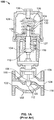
- FIG. 2A illustrates an example manual override apparatus 200.
- the example override apparatus 200 includes an override mechanism or drive member 202 to manually operate an actuator, and a support frame or base 204 that mounts the override mechanism or drive member 202 to an actuator.
- the override mechanism or drive member 202 has a threaded member 206 coupled to a rotating member 208.
- the rotating member can be a hand wheel 208 having a bushing 210 located substantially near its center and a handle 212.
- the bushing 210 of the hand wheel 208 is coaxially coupled to a threaded thrust nut 214 having an internally threaded body 216 ( FIG. 2B ) and a head 218.
- the threaded member 206 is shown by way of example as an externally threaded elongated screw.
- the thrust nut 214 is threadably engaged with the elongated screw 206 such that rotating the hand wheel 208 in either a clockwise or counter-clockwise direction about a longitudinal axis 219 of the elongated screw 206 causes the elongated screw 206 to move (e.g., extend or retract) along a longitudinal or linear path.
- the bushing 210 of the hand wheel 208 can be threaded and can be threadably engaged with the elongated screw 206.
- the upper end of the elongated screw 206 can be formed in a square or other polygonal shape to receive a crank, a hand wheel, a wrench, etc., for manual rotation of the elongated screw 206.
- a cap 207 may be included to cover the elongated screw 206 to protect it from dirt and/or damage.
- a collar 222 is coupled to a lowermost end portion 224 ( FIG. 2B ) of the elongated screw 206.
- the collar 222 has an outer wall including a groove or channel 226 formed therein to retain a clip 300 ( FIG. 3B ), and has stepped inner or interior walls 228a and 228b separated by the groove 226 and which are sized to receive and engage the stem of the actuator as discussed below.
- the collar 222 and the elongated screw 206 are integrally formed as a substantially unitary or single piece structure via any suitable process(es) such as, for example, machining, etc.
- the collar 222 and the elongated screw 206 can be formed as separate pieces and coupled via mechanical fasteners, welding, or any suitable fastening mechanism(s).
- the drive member 202 is substantially coaxially aligned with the stem 106 so that the stem 106 can extend through the casing 128 of the actuator 100 ( FIG. 1A ) to selectively engage the drive member 202 to enable manual operation of the actuator 100.
- a cylindrical member or override stem 230 is operatively coupled to the actuator stem 106 at one end to form an extended actuator stem.
- the cylindrical member or override stem 230 has a lip 232 formed by a recessed groove 234 at its other end.
- the lip 232 of the override stem 230 is sized to be removably coupled to the collar 222 such that the lip 232 engages the stepped interior wall 228a of the collar 222.
- the override stem 230 replaces the piston nut 132 ( FIG. 1A ) in a piston actuator, or the hub nut 164 ( FIG. 1B ) in a diaphragm actuator.
- the actuator stem 106 is threaded into a threaded bore 236 of the override stem 230 to couple the override stem 230 to the piston 126.
- the override stem 230 can be operatively coupled to the actuator stem 106 and/or the piston 126 via mechanical fasteners, welding, or other suitable fastening mechanism(s).
- the example manual override apparatus 200 does not interfere or affect the operation of the actuator 100 when the collar 222 is not engaged with the override stem 230.
- the support frame or base 204 may have a generally conically shaped body 238 having a flange 240 at one end, and an aperture 242 for receiving the elongated screw 206 and thrust nut 214 at the other end.
- the aperture 242 has a stepped interior wall 244 that is sized to receive the head 218 of the thrust nut 214 to enable it to rotate therein.
- a retaining washer 246 is fastened via screws 248a and 248b to an interior surface 250 of the support frame or base 204.
- the stepped interior wall 244 and the retaining washer 246 secure the thrust nut 214 in its position as the elongated screw 206 rotates and travels or moves along the longitudinal axis 219.
- the aperture 242 can be threaded to threadably engage the elongated screw 206.
- the support frame or base 204 can be made of aluminum, steel, or any other suitable material.
- the support frame or base 204 can have an opening portion 252 via which the collar 222 and the override stem 230 are accessible from outside of the support frame or base 204 to selectively engage the manual override apparatus 200 to the actuator 100.
- a cover or a door may cover the opening 252 to prevent dirt and/or debris from contaminating the elongated screw 206, the collar 222 and/or the override stem 230.
- the flange 240 of the support frame or base 204 has a plurality of mounting holes 254 therethrough for mounting the support frame or base 204 to the casing 128 of the actuator 100.
- the support frame or base 204 can be mounted to the casing 128 via bolts 256 or any other suitable fasteners that pass through the plurality of mounting holes 254 and engage corresponding threaded bores 258 in the casing 128.
- the support frame or base 204 can be fastened to the casing 128 by other means such as, for example, welding, rivets, hooks, clips, etc.
- the support frame or base 204 and the casing 128 can be integrally formed (e.g., via injection molding) to produce a unitary or single piece structure.
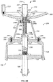
- FIG. 2B illustrates the manual override 200 apparatus selectively and operatively engaged to an actuator.
- the collar 222 is selectively engaged to the override stem 230 to expeditiously open or close a valve, depending on the configuration of the valve (i.e., fluid-to-open, fluid-to-close, etc.), in an emergency situation without requiring manual engagement of the collar 222 and the override stem 230.
- the collar 222 engages to the override stem 230 to enable manual operation of the actuator 100 between a first direction and a second direction that is opposite the first direction (e.g., to move the stem 106 of the actuator 100 in both directions along the longitudinal axis 219).
- FIGS. 3A and 3B illustrate an example removable U-shaped clip 300 that is used with the example manual override apparatus 200 to couple the collar 222 to the override stem 230 to manually control the position of an actuator and a valve coupled to the actuator.
- the clip 300 is sized to engage the grooves 226 and 234 ( FIG. 2A ), thereby coupling the collar 222 to the override stem 230.
- the clip 300 may have a ring 301 to aid with insertion and removal of the clip 300 from the collar 222.
- a pneumatic actuator e.g., the actuator 100
- the manual override apparatus 200 is disengaged ( FIG. 2A ) from the override stem 230 and the override stem 230 can move freely with the piston 126 without interference from the manual override apparatus 200.
- an operator rotates the hand wheel 208 to extend the elongated screw 206 to selectively engage the collar 222 to the override stem 230 to manually move the stem 106 of the actuator 100.
- the clip 300 is coupled to the collar 222 via the groove 226 when the manual override apparatus 200 is disengaged from the override stem 230.
- the clip 300 expands over the lip 232 and snap fits into the groove 234 to couple the collar 222 and the override stem 230.
- the manual override apparatus 200 engages the actuator without requiring manual engagement of the collar 222 and the override stem 230.
- the groove 234 of the override stem 230 substantially aligns with the groove 226 of the collar 222.
- the clip 300 can be manually inserted in the grooves 226 and 234 via the base opening 252 when the collar 222 is engaged with the override stem 230. In this manner, the collar 222 engages the override stem 230 and rotation of the hand wheel can manually operate the actuator in one direction until the clip 300 is manually inserted in grooves 226 and 234.
- an operator can rotate the hand wheel 208, either clockwise or counter-clockwise, to cause the elongated screw 206 to extend or retract and, thus, cause the collar 222 and the override stem 230 to travel in a longitudinal or linear path along the axis 219. Due to its coupling to the actuator stem 106, the override stem 230 causes the valve stem 108 and the valve plug 112 to travel along the axis 219.
- the range of travel includes, at one extreme, a closed position at which the valve plug 112 is in sealing engagement with the valve seat 118, and at another extreme, a fully open maximum flow rate position at which the valve stem 108 is moved to the full extent of its permitted travel.
- an operator To disengage the manual override and return the valve to automatic operation, an operator, through the access opening in the support frame or base 204, removes the clip 300 and rotates the hand wheel 208 to retract the elongated screw 206 and the collar 222 to the position shown in FIG. 2A and, thereby disengaging the collar 222 from the override stem 230.
- an operator can reinsert the clip 300 into groove 226 of the collar 222.
- the clip 300 can be attached to the manual override apparatus 200 (e.g., to the base 204) via a wire, string, etc.
- the manual override apparatus 200 can be retrofitted to existing control valves that are already operating in the field.
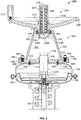
- FIG. 4 illustrates the control valve 101 of FIG. 1B retrofitted with the manual override apparatus 200.
- the vent plug 174 and the hub nut 164 are removed and replaced with the override stem 230.
- the override stem 230 is coupled to the actuator stem 162 of the diaphragm 154 by fastening the override stem 230 to the actuator stem 162.
- the support frame or base 204 of the manual override 200 can be mounted directly to the casing 150 of the valve.
- a plate 402 can be used if the flange 240 of the support frame or base 204 extends beyond the width of the casing 150 or if the surface of the casing 150 is such that the flange 240 cannot be mounted thereon.
- the support frame or base 204 is attached to the plate 402 via bolts 404 through a plurality of holes 406 in the plate 402 that correspond with the holes 254 of the flange 240.
- the plate 402 is then attached to the upper portion 158 of the casing 150 via cap screws 408 that extend through a plurality of holes 410 in the upper portion 158 of the casing 150 and engage a plurality of threaded bores 412 in the plate 402.
- the support frame or base 204 can be attached to the plate 402 and/or the plate 402 can be attached to the casing 150 by welding, fasteners, or other suitable fastening mechanism(s).
- the flange 240 can be curved to substantially match the contour of the casing 150 and mounted thereon.
Landscapes
- Engineering & Computer Science (AREA)
- General Engineering & Computer Science (AREA)
- Mechanical Engineering (AREA)
- Mechanically-Actuated Valves (AREA)
- Fluid-Driven Valves (AREA)
- Transmission Devices (AREA)
Applications Claiming Priority (2)
| Application Number | Priority Date | Filing Date | Title |
|---|---|---|---|
| US11/859,408 US8282070B2 (en) | 2007-09-21 | 2007-09-21 | Apparatus and methods for manual override operation of a linear actuator |
| PCT/US2008/076251 WO2009039042A1 (en) | 2007-09-21 | 2008-09-12 | Apparatus and methods for manual override operation of a linear actuator |
Publications (2)
| Publication Number | Publication Date |
|---|---|
| EP2191181A1 EP2191181A1 (en) | 2010-06-02 |
| EP2191181B1 true EP2191181B1 (en) | 2019-06-26 |
Family
ID=40091428
Family Applications (1)
| Application Number | Title | Priority Date | Filing Date |
|---|---|---|---|
| EP08831861.3A Active EP2191181B1 (en) | 2007-09-21 | 2008-09-12 | Apparatus and methods for manual override operation of a linear actuator |
Country Status (8)
| Country | Link |
|---|---|
| US (1) | US8282070B2 (enExample) |
| EP (1) | EP2191181B1 (enExample) |
| JP (1) | JP5462169B2 (enExample) |
| CN (1) | CN101828060B (enExample) |
| BR (1) | BRPI0816962A2 (enExample) |
| CA (1) | CA2699900C (enExample) |
| MX (1) | MX2010002969A (enExample) |
| WO (1) | WO2009039042A1 (enExample) |
Families Citing this family (19)
| Publication number | Priority date | Publication date | Assignee | Title |
|---|---|---|---|---|
| CA2823110C (en) * | 2010-12-28 | 2016-07-19 | Emerson Process Management (Tianjin) Valves Co., Ltd | Hydraulic actuating device for a sliding stem control valve assembly |
| FR2989143B1 (fr) * | 2012-04-05 | 2014-04-04 | E M T 74 | Actionneur a pression et/ou depression |
| CN102900859B (zh) * | 2012-10-29 | 2014-02-12 | 宝鸡石油机械有限责任公司 | 水下液压驱动型平板闸阀 |
| US9568117B2 (en) | 2012-11-16 | 2017-02-14 | Ge Oil & Gas Pressure Control Lp | Combination diaphragm piston actuator |
| US8910658B2 (en) | 2012-12-17 | 2014-12-16 | Vetco Gray Inc. | Swivel top shaft valve actuator |
| US11326712B2 (en) | 2012-12-31 | 2022-05-10 | Baker Hughes Oilfield Operations Llc | No-bolt valve assembly system |
| US9759240B2 (en) | 2012-12-31 | 2017-09-12 | Ge Oil & Gas Pressure Control Lp | No-bolt security latching system |
| US10480675B2 (en) | 2012-12-31 | 2019-11-19 | Ge Oil & Gas Pressure Control Lp | No-bolt security latching system |
| US10132422B2 (en) | 2012-12-31 | 2018-11-20 | Ge Oil & Gas Pressure Control Lp | Compound express actuator connection |
| US11015733B2 (en) | 2012-12-31 | 2021-05-25 | Ge Oil & Gas Pressure Control Lp | No-bolt latching system |
| US11015732B2 (en) | 2012-12-31 | 2021-05-25 | Ge Oil & Gas Pressure Control Lp | Axially restricted pressure shuttle |
| JP2017503123A (ja) | 2013-11-28 | 2017-01-26 | ハム−レット (イスラエル−カナダ) リミテッド | 流体の流れを制御および調整するための弁装置 |
| US10215303B2 (en) * | 2015-05-01 | 2019-02-26 | Fisher Controls International Llc | Adjustable travel stop for a piston actuator |
| CN105020463A (zh) * | 2015-07-20 | 2015-11-04 | 苏州华达仪器设备有限公司 | 一种压力阀手轮 |
| US20190055979A1 (en) * | 2017-08-17 | 2019-02-21 | Fisher Controls International Llc | Weld studs for use in fluid control bodies |
| US11920687B2 (en) | 2020-03-25 | 2024-03-05 | Baker Hughes Oilfield Operations Llc | Valve end replacement system and method |
| US11466783B2 (en) | 2020-03-25 | 2022-10-11 | Baker Hughes Oilfield Operations Llc | Side entry valve |
| CN112628457B (zh) * | 2020-12-31 | 2022-02-18 | 江苏兰格特自动化设备有限公司 | 一种气动执行机构的扭矩限制装置 |
| US12196336B2 (en) | 2023-01-12 | 2025-01-14 | Magdrive Technologies, Inc. | Electromagnetically activated rising stem valve |
Family Cites Families (34)
| Publication number | Priority date | Publication date | Assignee | Title |
|---|---|---|---|---|
| US935856A (en) * | 1908-04-29 | 1909-10-05 | Jeremiah O'meara | Valve. |
| US2403427A (en) * | 1944-01-27 | 1946-07-02 | Skinner Engine Co | Valve mechanism |
| US2630829A (en) * | 1947-07-30 | 1953-03-10 | Shafer Valve Co | Valve operating mechanism |
| US2890014A (en) * | 1955-12-19 | 1959-06-09 | Worthington Corp | Pressure responsive valve |
| US2885172A (en) * | 1956-07-17 | 1959-05-05 | Pan American Petroleum Corp | Safety valve with mechanical and hydraulic operator |
| DE1113344B (de) | 1957-12-18 | 1961-08-31 | Acf Ind Inc | Kombinierter Druckmittel- und Handantrieb fuer Ventile u. dgl. taetige Verschluesse |
| FR1300618A (fr) | 1961-09-18 | 1962-08-03 | Jansen Gmbh Th | Vanne d'arrêt à surfaces de joint obliques |
| US3290003A (en) * | 1962-10-29 | 1966-12-06 | G & H Products Corp | Valve construction facilitating removal of parts |
| US3734455A (en) * | 1971-09-21 | 1973-05-22 | Acf Ind Inc | Safety device for a fluid cylinder valve actuator |
| USRE29322E (en) * | 1971-09-29 | 1977-07-26 | Teledyne Merla, div. of Teledyne, Inc. | Valve and actuator assembly |
| US3842854A (en) * | 1973-04-16 | 1974-10-22 | Acf Ind Inc | Heat responsive safety device for manual gate valve operators |
| US3842690A (en) * | 1973-05-10 | 1974-10-22 | Res Eng Co | Automatically disengageable manual control |
| US4194718A (en) * | 1978-06-14 | 1980-03-25 | Cameron Iron Works, Inc. | Choke |
| JPS5728967U (enExample) * | 1980-07-28 | 1982-02-16 | ||
| US4619434A (en) * | 1981-02-17 | 1986-10-28 | Axelson, Inc. | Heat sensitive motor valve jack |
| JPS57190182U (enExample) * | 1981-05-27 | 1982-12-02 | ||
| US4414995A (en) * | 1982-04-08 | 1983-11-15 | Spencer Larry K | Three-way hydraulic controller |
| US4605039A (en) * | 1984-10-04 | 1986-08-12 | Stewart-Warner Corporation | Runaway protective fuse valve |
| ES2030811T3 (es) * | 1988-08-18 | 1992-11-16 | Festo Kg | Dispositivo lineal de impulsion. |
| US4921207A (en) * | 1989-08-22 | 1990-05-01 | Cameron Iron Works Usa, Inc. | Actuated gate valve with manual override |
| JPH03100632U (enExample) * | 1990-02-02 | 1991-10-21 | ||
| JPH0712783Y2 (ja) * | 1992-03-27 | 1995-03-29 | ティヴィバルブ株式会社 | バルブアクチュエーター |
| FR2712955B1 (fr) | 1993-11-25 | 1995-12-22 | Pyromeca | Dispositif de manÓoeuvre d'une vanne à obturateur se déplaçant par translation. |
| WO1995023937A1 (en) * | 1994-03-04 | 1995-09-08 | Safoco, Inc. | Valve actuator apparatus and method |
| US5477752A (en) * | 1994-03-07 | 1995-12-26 | Dyna-Torque Company, Inc. | Valve actuator declutch mechanism |
| JP3007230U (ja) * | 1994-07-27 | 1995-02-14 | 株式会社栗本鐵工所 | 仕切弁の手動開閉装置 |
| US5531205A (en) * | 1995-03-31 | 1996-07-02 | Siemens Electric Limited | Rotary diesel electric EGR valve |
| FR2817940B1 (fr) | 2000-12-08 | 2004-04-30 | Atofina | Robinet a commande par servomoteur pour recipient de fluides toxiques |
| US6722528B2 (en) * | 2002-03-14 | 2004-04-20 | Fisher Controls International, Inc. | Rotary pneumatic actuator |
| JP4354794B2 (ja) * | 2002-12-18 | 2009-10-28 | 株式会社パイオラックス | チェッカー付きコネクタ |
| JP2007528478A (ja) | 2004-03-10 | 2007-10-11 | スワゲロック カンパニー | 手動オーバーライドを備える流体デバイスアクチュエーター |
| EP1793114B1 (de) | 2005-12-02 | 2013-05-15 | Behr Thermot-tronik GmbH | Vorrichtung, insbesondere Abgasrückführventileinrichtung, zum Steuern oder Regeln eines Fluidstroms |
| JP4517371B2 (ja) * | 2006-12-25 | 2010-08-04 | Smc株式会社 | 流量調整弁 |
| JP5001754B2 (ja) * | 2007-08-29 | 2012-08-15 | 岩井機械工業株式会社 | 二重弁栓装置 |
-
2007
- 2007-09-21 US US11/859,408 patent/US8282070B2/en active Active
-
2008
- 2008-09-12 CN CN200880112173.5A patent/CN101828060B/zh active Active
- 2008-09-12 BR BRPI0816962 patent/BRPI0816962A2/pt not_active Application Discontinuation
- 2008-09-12 JP JP2010525897A patent/JP5462169B2/ja not_active Expired - Fee Related
- 2008-09-12 EP EP08831861.3A patent/EP2191181B1/en active Active
- 2008-09-12 WO PCT/US2008/076251 patent/WO2009039042A1/en not_active Ceased
- 2008-09-12 CA CA 2699900 patent/CA2699900C/en active Active
- 2008-09-12 MX MX2010002969A patent/MX2010002969A/es active IP Right Grant
Non-Patent Citations (1)
| Title |
|---|
| None * |
Also Published As
| Publication number | Publication date |
|---|---|
| CA2699900C (en) | 2014-10-28 |
| JP2010540849A (ja) | 2010-12-24 |
| US20090078894A1 (en) | 2009-03-26 |
| EP2191181A1 (en) | 2010-06-02 |
| CN101828060A (zh) | 2010-09-08 |
| CN101828060B (zh) | 2015-02-25 |
| BRPI0816962A2 (pt) | 2015-03-24 |
| JP5462169B2 (ja) | 2014-04-02 |
| CA2699900A1 (en) | 2009-03-26 |
| MX2010002969A (es) | 2010-04-01 |
| WO2009039042A1 (en) | 2009-03-26 |
| US8282070B2 (en) | 2012-10-09 |
Similar Documents
| Publication | Publication Date | Title |
|---|---|---|
| EP2191181B1 (en) | Apparatus and methods for manual override operation of a linear actuator | |
| CA2750277C (en) | Manual override apparatus for linear actuators | |
| AU2012362670B2 (en) | Mounting assemblies for use with fluid control devices | |
| JP5571563B2 (ja) | 閉鎖部材と弁ステムとを整合させる装置および方法 | |
| US6585228B1 (en) | Electric valve actuator with eddy current clutch | |
| US9500294B2 (en) | Hybrid manual and hydraulic actuator override | |
| CA2705070C (en) | Rotary valve lever apparatus having interchangeable shaft adaptor inserts | |
| US20040004201A1 (en) | Balanced valve with actuator | |
| US20170016544A1 (en) | Valve Device for Controlling and Adjusting Fluid Passage | |
| US9228674B2 (en) | Methods and apparatus to assemble actuators | |
| US20230213100A1 (en) | Actuator for Gate Valve and Method of Attachment | |
| NZ272302A (en) | Pneumatic valve actuator; details regarding means for supplying fluid pressure to the actuator cylinder |
Legal Events
| Date | Code | Title | Description |
|---|---|---|---|
| PUAI | Public reference made under article 153(3) epc to a published international application that has entered the european phase |
Free format text: ORIGINAL CODE: 0009012 |
|
| 17P | Request for examination filed |
Effective date: 20100331 |
|
| AK | Designated contracting states |
Kind code of ref document: A1 Designated state(s): AT BE BG CH CY CZ DE DK EE ES FI FR GB GR HR HU IE IS IT LI LT LU LV MC MT NL NO PL PT RO SE SI SK TR |
|
| AX | Request for extension of the european patent |
Extension state: AL BA MK RS |
|
| DAX | Request for extension of the european patent (deleted) | ||
| 17Q | First examination report despatched |
Effective date: 20131011 |
|
| STAA | Information on the status of an ep patent application or granted ep patent |
Free format text: STATUS: EXAMINATION IS IN PROGRESS |
|
| GRAP | Despatch of communication of intention to grant a patent |
Free format text: ORIGINAL CODE: EPIDOSNIGR1 |
|
| STAA | Information on the status of an ep patent application or granted ep patent |
Free format text: STATUS: GRANT OF PATENT IS INTENDED |
|
| INTG | Intention to grant announced |
Effective date: 20190109 |
|
| GRAS | Grant fee paid |
Free format text: ORIGINAL CODE: EPIDOSNIGR3 |
|
| GRAA | (expected) grant |
Free format text: ORIGINAL CODE: 0009210 |
|
| STAA | Information on the status of an ep patent application or granted ep patent |
Free format text: STATUS: THE PATENT HAS BEEN GRANTED |
|
| RAP1 | Party data changed (applicant data changed or rights of an application transferred) |
Owner name: FISHER CONTROLS INTERNATIONAL LLC |
|
| AK | Designated contracting states |
Kind code of ref document: B1 Designated state(s): AT BE BG CH CY CZ DE DK EE ES FI FR GB GR HR HU IE IS IT LI LT LU LV MC MT NL NO PL PT RO SE SI SK TR |
|
| REG | Reference to a national code |
Ref country code: GB Ref legal event code: FG4D |
|
| REG | Reference to a national code |
Ref country code: CH Ref legal event code: EP |
|
| REG | Reference to a national code |
Ref country code: DE Ref legal event code: R096 Ref document number: 602008060527 Country of ref document: DE |
|
| REG | Reference to a national code |
Ref country code: AT Ref legal event code: REF Ref document number: 1148685 Country of ref document: AT Kind code of ref document: T Effective date: 20190715 |
|
| REG | Reference to a national code |
Ref country code: IE Ref legal event code: FG4D |
|
| REG | Reference to a national code |
Ref country code: NL Ref legal event code: MP Effective date: 20190626 |
|
| PG25 | Lapsed in a contracting state [announced via postgrant information from national office to epo] |
Ref country code: SE Free format text: LAPSE BECAUSE OF FAILURE TO SUBMIT A TRANSLATION OF THE DESCRIPTION OR TO PAY THE FEE WITHIN THE PRESCRIBED TIME-LIMIT Effective date: 20190626 Ref country code: LT Free format text: LAPSE BECAUSE OF FAILURE TO SUBMIT A TRANSLATION OF THE DESCRIPTION OR TO PAY THE FEE WITHIN THE PRESCRIBED TIME-LIMIT Effective date: 20190626 Ref country code: FI Free format text: LAPSE BECAUSE OF FAILURE TO SUBMIT A TRANSLATION OF THE DESCRIPTION OR TO PAY THE FEE WITHIN THE PRESCRIBED TIME-LIMIT Effective date: 20190626 Ref country code: HR Free format text: LAPSE BECAUSE OF FAILURE TO SUBMIT A TRANSLATION OF THE DESCRIPTION OR TO PAY THE FEE WITHIN THE PRESCRIBED TIME-LIMIT Effective date: 20190626 Ref country code: NO Free format text: LAPSE BECAUSE OF FAILURE TO SUBMIT A TRANSLATION OF THE DESCRIPTION OR TO PAY THE FEE WITHIN THE PRESCRIBED TIME-LIMIT Effective date: 20190926 |
|
| REG | Reference to a national code |
Ref country code: LT Ref legal event code: MG4D |
|
| PG25 | Lapsed in a contracting state [announced via postgrant information from national office to epo] |
Ref country code: GR Free format text: LAPSE BECAUSE OF FAILURE TO SUBMIT A TRANSLATION OF THE DESCRIPTION OR TO PAY THE FEE WITHIN THE PRESCRIBED TIME-LIMIT Effective date: 20190927 Ref country code: LV Free format text: LAPSE BECAUSE OF FAILURE TO SUBMIT A TRANSLATION OF THE DESCRIPTION OR TO PAY THE FEE WITHIN THE PRESCRIBED TIME-LIMIT Effective date: 20190626 Ref country code: BG Free format text: LAPSE BECAUSE OF FAILURE TO SUBMIT A TRANSLATION OF THE DESCRIPTION OR TO PAY THE FEE WITHIN THE PRESCRIBED TIME-LIMIT Effective date: 20190926 |
|
| REG | Reference to a national code |
Ref country code: AT Ref legal event code: MK05 Ref document number: 1148685 Country of ref document: AT Kind code of ref document: T Effective date: 20190626 |
|
| PG25 | Lapsed in a contracting state [announced via postgrant information from national office to epo] |
Ref country code: NL Free format text: LAPSE BECAUSE OF FAILURE TO SUBMIT A TRANSLATION OF THE DESCRIPTION OR TO PAY THE FEE WITHIN THE PRESCRIBED TIME-LIMIT Effective date: 20190626 Ref country code: EE Free format text: LAPSE BECAUSE OF FAILURE TO SUBMIT A TRANSLATION OF THE DESCRIPTION OR TO PAY THE FEE WITHIN THE PRESCRIBED TIME-LIMIT Effective date: 20190626 Ref country code: AT Free format text: LAPSE BECAUSE OF FAILURE TO SUBMIT A TRANSLATION OF THE DESCRIPTION OR TO PAY THE FEE WITHIN THE PRESCRIBED TIME-LIMIT Effective date: 20190626 Ref country code: PT Free format text: LAPSE BECAUSE OF FAILURE TO SUBMIT A TRANSLATION OF THE DESCRIPTION OR TO PAY THE FEE WITHIN THE PRESCRIBED TIME-LIMIT Effective date: 20191028 Ref country code: RO Free format text: LAPSE BECAUSE OF FAILURE TO SUBMIT A TRANSLATION OF THE DESCRIPTION OR TO PAY THE FEE WITHIN THE PRESCRIBED TIME-LIMIT Effective date: 20190626 Ref country code: CZ Free format text: LAPSE BECAUSE OF FAILURE TO SUBMIT A TRANSLATION OF THE DESCRIPTION OR TO PAY THE FEE WITHIN THE PRESCRIBED TIME-LIMIT Effective date: 20190626 Ref country code: SK Free format text: LAPSE BECAUSE OF FAILURE TO SUBMIT A TRANSLATION OF THE DESCRIPTION OR TO PAY THE FEE WITHIN THE PRESCRIBED TIME-LIMIT Effective date: 20190626 |
|
| PG25 | Lapsed in a contracting state [announced via postgrant information from national office to epo] |
Ref country code: IS Free format text: LAPSE BECAUSE OF FAILURE TO SUBMIT A TRANSLATION OF THE DESCRIPTION OR TO PAY THE FEE WITHIN THE PRESCRIBED TIME-LIMIT Effective date: 20191026 Ref country code: ES Free format text: LAPSE BECAUSE OF FAILURE TO SUBMIT A TRANSLATION OF THE DESCRIPTION OR TO PAY THE FEE WITHIN THE PRESCRIBED TIME-LIMIT Effective date: 20190626 Ref country code: IT Free format text: LAPSE BECAUSE OF FAILURE TO SUBMIT A TRANSLATION OF THE DESCRIPTION OR TO PAY THE FEE WITHIN THE PRESCRIBED TIME-LIMIT Effective date: 20190626 |
|
| PG25 | Lapsed in a contracting state [announced via postgrant information from national office to epo] |
Ref country code: TR Free format text: LAPSE BECAUSE OF FAILURE TO SUBMIT A TRANSLATION OF THE DESCRIPTION OR TO PAY THE FEE WITHIN THE PRESCRIBED TIME-LIMIT Effective date: 20190626 |
|
| REG | Reference to a national code |
Ref country code: DE Ref legal event code: R119 Ref document number: 602008060527 Country of ref document: DE |
|
| PG25 | Lapsed in a contracting state [announced via postgrant information from national office to epo] |
Ref country code: DK Free format text: LAPSE BECAUSE OF FAILURE TO SUBMIT A TRANSLATION OF THE DESCRIPTION OR TO PAY THE FEE WITHIN THE PRESCRIBED TIME-LIMIT Effective date: 20190626 Ref country code: PL Free format text: LAPSE BECAUSE OF FAILURE TO SUBMIT A TRANSLATION OF THE DESCRIPTION OR TO PAY THE FEE WITHIN THE PRESCRIBED TIME-LIMIT Effective date: 20190626 |
|
| PG25 | Lapsed in a contracting state [announced via postgrant information from national office to epo] |
Ref country code: IS Free format text: LAPSE BECAUSE OF FAILURE TO SUBMIT A TRANSLATION OF THE DESCRIPTION OR TO PAY THE FEE WITHIN THE PRESCRIBED TIME-LIMIT Effective date: 20200224 Ref country code: MC Free format text: LAPSE BECAUSE OF FAILURE TO SUBMIT A TRANSLATION OF THE DESCRIPTION OR TO PAY THE FEE WITHIN THE PRESCRIBED TIME-LIMIT Effective date: 20190626 |
|
| REG | Reference to a national code |
Ref country code: CH Ref legal event code: PL |
|
| PLBE | No opposition filed within time limit |
Free format text: ORIGINAL CODE: 0009261 |
|
| STAA | Information on the status of an ep patent application or granted ep patent |
Free format text: STATUS: NO OPPOSITION FILED WITHIN TIME LIMIT |
|
| PG2D | Information on lapse in contracting state deleted |
Ref country code: IS |
|
| PG25 | Lapsed in a contracting state [announced via postgrant information from national office to epo] |
Ref country code: LU Free format text: LAPSE BECAUSE OF NON-PAYMENT OF DUE FEES Effective date: 20190912 Ref country code: IE Free format text: LAPSE BECAUSE OF NON-PAYMENT OF DUE FEES Effective date: 20190912 Ref country code: CH Free format text: LAPSE BECAUSE OF NON-PAYMENT OF DUE FEES Effective date: 20190930 Ref country code: DE Free format text: LAPSE BECAUSE OF NON-PAYMENT OF DUE FEES Effective date: 20200401 Ref country code: LI Free format text: LAPSE BECAUSE OF NON-PAYMENT OF DUE FEES Effective date: 20190930 |
|
| 26N | No opposition filed |
Effective date: 20200603 |
|
| REG | Reference to a national code |
Ref country code: BE Ref legal event code: MM Effective date: 20190930 |
|
| PG25 | Lapsed in a contracting state [announced via postgrant information from national office to epo] |
Ref country code: BE Free format text: LAPSE BECAUSE OF NON-PAYMENT OF DUE FEES Effective date: 20190930 Ref country code: SI Free format text: LAPSE BECAUSE OF FAILURE TO SUBMIT A TRANSLATION OF THE DESCRIPTION OR TO PAY THE FEE WITHIN THE PRESCRIBED TIME-LIMIT Effective date: 20190626 |
|
| PG25 | Lapsed in a contracting state [announced via postgrant information from national office to epo] |
Ref country code: CY Free format text: LAPSE BECAUSE OF FAILURE TO SUBMIT A TRANSLATION OF THE DESCRIPTION OR TO PAY THE FEE WITHIN THE PRESCRIBED TIME-LIMIT Effective date: 20190626 |
|
| PG25 | Lapsed in a contracting state [announced via postgrant information from national office to epo] |
Ref country code: MT Free format text: LAPSE BECAUSE OF FAILURE TO SUBMIT A TRANSLATION OF THE DESCRIPTION OR TO PAY THE FEE WITHIN THE PRESCRIBED TIME-LIMIT Effective date: 20190626 Ref country code: HU Free format text: LAPSE BECAUSE OF FAILURE TO SUBMIT A TRANSLATION OF THE DESCRIPTION OR TO PAY THE FEE WITHIN THE PRESCRIBED TIME-LIMIT; INVALID AB INITIO Effective date: 20080912 |
|
| P01 | Opt-out of the competence of the unified patent court (upc) registered |
Effective date: 20230526 |
|
| PGFP | Annual fee paid to national office [announced via postgrant information from national office to epo] |
Ref country code: FR Payment date: 20230822 Year of fee payment: 16 |
|
| PG25 | Lapsed in a contracting state [announced via postgrant information from national office to epo] |
Ref country code: FR Free format text: LAPSE BECAUSE OF NON-PAYMENT OF DUE FEES Effective date: 20240930 |
|
| PGFP | Annual fee paid to national office [announced via postgrant information from national office to epo] |
Ref country code: GB Payment date: 20250822 Year of fee payment: 18 |