EP2190561B1 - Module de filtre et empilement de ces modules en un système de filtre - Google Patents
Module de filtre et empilement de ces modules en un système de filtre Download PDFInfo
- Publication number
- EP2190561B1 EP2190561B1 EP08801110A EP08801110A EP2190561B1 EP 2190561 B1 EP2190561 B1 EP 2190561B1 EP 08801110 A EP08801110 A EP 08801110A EP 08801110 A EP08801110 A EP 08801110A EP 2190561 B1 EP2190561 B1 EP 2190561B1
- Authority
- EP
- European Patent Office
- Prior art keywords
- filter module
- functional
- connection unit
- membrane
- pressure pipe
- Prior art date
- Legal status (The legal status is an assumption and is not a legal conclusion. Google has not performed a legal analysis and makes no representation as to the accuracy of the status listed.)
- Not-in-force
Links
- 239000012528 membrane Substances 0.000 claims abstract description 66
- 239000007788 liquid Substances 0.000 claims abstract description 33
- 239000000706 filtrate Substances 0.000 claims abstract description 14
- XLYOFNOQVPJJNP-UHFFFAOYSA-N water Substances O XLYOFNOQVPJJNP-UHFFFAOYSA-N 0.000 claims abstract description 11
- 239000012530 fluid Substances 0.000 claims abstract 3
- 239000012465 retentate Substances 0.000 claims description 19
- 239000000463 material Substances 0.000 claims description 3
- 230000000903 blocking effect Effects 0.000 claims 1
- 238000007599 discharging Methods 0.000 claims 1
- 238000002347 injection Methods 0.000 claims 1
- 239000007924 injection Substances 0.000 claims 1
- 210000004379 membrane Anatomy 0.000 description 62
- 239000012466 permeate Substances 0.000 description 14
- 238000007789 sealing Methods 0.000 description 14
- 210000002445 nipple Anatomy 0.000 description 9
- 238000001223 reverse osmosis Methods 0.000 description 6
- 238000013461 design Methods 0.000 description 5
- 229910021642 ultra pure water Inorganic materials 0.000 description 4
- 239000012498 ultrapure water Substances 0.000 description 4
- 239000012459 cleaning agent Substances 0.000 description 3
- 239000000645 desinfectant Substances 0.000 description 3
- 230000008439 repair process Effects 0.000 description 3
- 238000004659 sterilization and disinfection Methods 0.000 description 3
- 239000000126 substance Substances 0.000 description 3
- 244000052616 bacterial pathogen Species 0.000 description 2
- 239000011324 bead Substances 0.000 description 2
- 238000004140 cleaning Methods 0.000 description 2
- 238000005516 engineering process Methods 0.000 description 2
- 238000001914 filtration Methods 0.000 description 2
- 235000013305 food Nutrition 0.000 description 2
- 238000001631 haemodialysis Methods 0.000 description 2
- 230000000322 hemodialysis Effects 0.000 description 2
- 238000004519 manufacturing process Methods 0.000 description 2
- 238000005259 measurement Methods 0.000 description 2
- 238000000034 method Methods 0.000 description 2
- 239000004033 plastic Substances 0.000 description 2
- 235000014676 Phragmites communis Nutrition 0.000 description 1
- 239000004952 Polyamide Substances 0.000 description 1
- 239000004760 aramid Substances 0.000 description 1
- 150000004984 aromatic diamines Chemical class 0.000 description 1
- 229920003235 aromatic polyamide Polymers 0.000 description 1
- 230000002146 bilateral effect Effects 0.000 description 1
- 239000007795 chemical reaction product Substances 0.000 description 1
- 239000012141 concentrate Substances 0.000 description 1
- 238000010276 construction Methods 0.000 description 1
- 238000011109 contamination Methods 0.000 description 1
- 238000009295 crossflow filtration Methods 0.000 description 1
- 238000000354 decomposition reaction Methods 0.000 description 1
- 238000007872 degassing Methods 0.000 description 1
- 238000011161 development Methods 0.000 description 1
- 238000009826 distribution Methods 0.000 description 1
- 230000000694 effects Effects 0.000 description 1
- 230000002349 favourable effect Effects 0.000 description 1
- 230000014759 maintenance of location Effects 0.000 description 1
- 239000007769 metal material Substances 0.000 description 1
- 244000005700 microbiome Species 0.000 description 1
- 210000000056 organ Anatomy 0.000 description 1
- 239000011368 organic material Substances 0.000 description 1
- 230000002093 peripheral effect Effects 0.000 description 1
- 229920002647 polyamide Polymers 0.000 description 1
- 229920005597 polymer membrane Polymers 0.000 description 1
- 238000001556 precipitation Methods 0.000 description 1
- 238000002203 pretreatment Methods 0.000 description 1
- 239000000047 product Substances 0.000 description 1
- 230000002787 reinforcement Effects 0.000 description 1
- 230000000717 retained effect Effects 0.000 description 1
- 150000003839 salts Chemical class 0.000 description 1
- 239000008399 tap water Substances 0.000 description 1
- 235000020679 tap water Nutrition 0.000 description 1
- 239000010409 thin film Substances 0.000 description 1
- 238000012546 transfer Methods 0.000 description 1
- 238000009827 uniform distribution Methods 0.000 description 1
Images


Classifications
-
- B—PERFORMING OPERATIONS; TRANSPORTING
- B01—PHYSICAL OR CHEMICAL PROCESSES OR APPARATUS IN GENERAL
- B01D—SEPARATION
- B01D65/00—Accessories or auxiliary operations, in general, for separation processes or apparatus using semi-permeable membranes
-
- B—PERFORMING OPERATIONS; TRANSPORTING
- B01—PHYSICAL OR CHEMICAL PROCESSES OR APPARATUS IN GENERAL
- B01D—SEPARATION
- B01D61/00—Processes of separation using semi-permeable membranes, e.g. dialysis, osmosis or ultrafiltration; Apparatus, accessories or auxiliary operations specially adapted therefor
- B01D61/02—Reverse osmosis; Hyperfiltration ; Nanofiltration
- B01D61/025—Reverse osmosis; Hyperfiltration
-
- B—PERFORMING OPERATIONS; TRANSPORTING
- B01—PHYSICAL OR CHEMICAL PROCESSES OR APPARATUS IN GENERAL
- B01D—SEPARATION
- B01D61/00—Processes of separation using semi-permeable membranes, e.g. dialysis, osmosis or ultrafiltration; Apparatus, accessories or auxiliary operations specially adapted therefor
- B01D61/02—Reverse osmosis; Hyperfiltration ; Nanofiltration
- B01D61/08—Apparatus therefor
-
- B—PERFORMING OPERATIONS; TRANSPORTING
- B01—PHYSICAL OR CHEMICAL PROCESSES OR APPARATUS IN GENERAL
- B01D—SEPARATION
- B01D63/00—Apparatus in general for separation processes using semi-permeable membranes
-
- B—PERFORMING OPERATIONS; TRANSPORTING
- B01—PHYSICAL OR CHEMICAL PROCESSES OR APPARATUS IN GENERAL
- B01D—SEPARATION
- B01D2313/00—Details relating to membrane modules or apparatus
- B01D2313/02—Specific tightening or locking mechanisms
-
- B—PERFORMING OPERATIONS; TRANSPORTING
- B01—PHYSICAL OR CHEMICAL PROCESSES OR APPARATUS IN GENERAL
- B01D—SEPARATION
- B01D2313/00—Details relating to membrane modules or apparatus
- B01D2313/04—Specific sealing means
-
- B—PERFORMING OPERATIONS; TRANSPORTING
- B01—PHYSICAL OR CHEMICAL PROCESSES OR APPARATUS IN GENERAL
- B01D—SEPARATION
- B01D2313/00—Details relating to membrane modules or apparatus
- B01D2313/10—Specific supply elements
-
- B—PERFORMING OPERATIONS; TRANSPORTING
- B01—PHYSICAL OR CHEMICAL PROCESSES OR APPARATUS IN GENERAL
- B01D—SEPARATION
- B01D2313/00—Details relating to membrane modules or apparatus
- B01D2313/10—Specific supply elements
- B01D2313/105—Supply manifolds
-
- B—PERFORMING OPERATIONS; TRANSPORTING
- B01—PHYSICAL OR CHEMICAL PROCESSES OR APPARATUS IN GENERAL
- B01D—SEPARATION
- B01D2313/00—Details relating to membrane modules or apparatus
- B01D2313/12—Specific discharge elements
-
- B—PERFORMING OPERATIONS; TRANSPORTING
- B01—PHYSICAL OR CHEMICAL PROCESSES OR APPARATUS IN GENERAL
- B01D—SEPARATION
- B01D2313/00—Details relating to membrane modules or apparatus
- B01D2313/12—Specific discharge elements
- B01D2313/125—Discharge manifolds
-
- B—PERFORMING OPERATIONS; TRANSPORTING
- B01—PHYSICAL OR CHEMICAL PROCESSES OR APPARATUS IN GENERAL
- B01D—SEPARATION
- B01D2313/00—Details relating to membrane modules or apparatus
- B01D2313/21—Specific headers, end caps
-
- B—PERFORMING OPERATIONS; TRANSPORTING
- B01—PHYSICAL OR CHEMICAL PROCESSES OR APPARATUS IN GENERAL
- B01D—SEPARATION
- B01D2313/00—Details relating to membrane modules or apparatus
- B01D2313/44—Cartridge types
-
- B—PERFORMING OPERATIONS; TRANSPORTING
- B01—PHYSICAL OR CHEMICAL PROCESSES OR APPARATUS IN GENERAL
- B01D—SEPARATION
- B01D2315/00—Details relating to the membrane module operation
- B01D2315/10—Cross-flow filtration
Definitions
- the invention relates to a filter module and its juxtaposition to a filter system.
- the system was conceived and developed as an application in the field of water treatment, especially as part of a reverse osmosis system. However, it is easily applicable to other applications e.g. Transfer gas filtration.
- this filter module consisting of a filter - also called membrane -, a pressure tube and a function / connection unit is designed as a quick-change filter and includes a dead space-free water supply.
- the special design of the filter module provides a closure technique for one-sided connection to a function / connection unit.
- Another feature is the stringing together of several filter modules to a filter system. Of particular importance is that the incoming and outgoing connections to the filter module always one-sided, i. take place at the functional / connection unit.
- Reverse osmosis plants are particularly useful for obtaining pure, germ-free water from tap water, e.g. for medical, pharmaceutical and food applications.
- the ultrapure water thus obtained is ideally germ-free due to the retention properties of the membrane and free of organic decomposition products. In reality, however, this is not necessarily true. Without special countermeasures, colonization of the permeate system with microorganisms can occur. It forms a so-called biofilm on the inner surfaces of the liquid-carrying system. This biofilm is also called fouling.
- Fouling describes the loss of permeate through the attachment of secondary layers on the membrane surface. This may be organic material, colloidal materials or inorganic salts that exceed the precipitation limits upon concentration.
- thermo-resistant polymer membranes for reverse osmosis are available, which are disinfected with water at 90 ° C. This measure initially serves only to reduce germs, but is of little help in removing the biofilm.
- Another possibility is to disinfect or purify reverse osmosis systems at suitable intervals.
- the interrupted normal operation and supplied to the liquid-carrying system, a chemical disinfectant or cleaning agent.
- a suitable exposure time follows a rinsing process, which serves to remove the introduced disinfectant or cleaning agent and its reaction products, so that then the normal supply operation can be resumed.
- This membrane exchange is carried out in the existing devices by a technician in such a way that first the entire reverse osmosis system shut down and by means of a tool, the three-piece filter module consisting of membrane element, pressure tube and connection unit is disassembled.
- a conventional structure is in illustration 1 shown.
- Another disadvantage is the exchange following chemical disinfection, which is necessary because during the repair and the high purity components of the connecting pipes or components were contaminated by technicians and tools.
- This aromatic polyamide is applied in an extremely thin layer ( ⁇ 0.3 microns) to a support membrane (or support layer).
- the membrane is therefore also called thin-film membrane.
- Another disadvantage of this technology is that the incoming and outgoing connections to the filter module are bilateral at both ends of the filter module.
- the US-A-5 401 399 discloses a modular cross-flow filtration system with prismatic units having multi-sided feed and permeate connections. The retentate is removed at the opposite end of the pressure tube.
- the JP 63 163002 , the DE 94 22 466 as well as the US-A-5,389,260 disclose modular filter systems with prismatic tops, but have no retentate connections because they are dead-end systems.
- the supplied liquid flows from the supply container (1) via the high-pressure pump (2) and the connection of the liquid supply (3), which is fixed to the cover of the pressure tube (48), via the pressure tube (4) in the membrane (5).
- the annular gap between the membrane and pressure tube inner side (21) is not flowed through because of the sealing lip of the membrane (8).
- a portion of the supplied liquid would lead to an insufficient membrane overflow due to the resulting bypass to the membrane.
- the missing overflow would then have to be compensated with a larger pump capacity.
- Via the filtrate connection (7), which is fastened to the cover (49) the ultrapure water flows to the outlet DP.
- the release valve (39) is opened and the ultrapure water flows back to the flow container (1).
- the Verschventil (9) is switched periodically.
- the module tube (4) in this case receives two covers (48/49), in which on the one hand the connection liquid supply (3) and on the other hand, the terminals for retentate and filtrate (6 and 7) are attached. To disassemble, open the covers (48/49). Before the connections (3/6/7) - which are usually designed as a high-pressure-resistant connection to solve. Only then can the Membrane to be removed. Because of the many leaks, frequent leaks are the result of repairs.
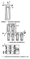
- FIG. 1 shows the scheme of the functional / connection unit (11) according to the invention.
- all 3 connections (3/7/6) are supplied on one side, ie at one end of the module tube, and that the annular gap between membrane and pressure tube inner side (21) is flushed through.
- This figure illustrates the scheme and, in particular, shows the possibility of modular serial and parallel switching to increase the filtrate capacity.
- This enlargement can be achieved by juxtaposing and connecting the function / connection unit (11). High-pressure connections are not necessary, as well as the membrane replacement can be performed without disconnection of the lines.
- the unneeded connections by means of connecting nipple 42, which is used here as an undrilled nipple, closed, or not created.
- the advantage lies in the uniform design of the functional / terminal units 11. The flow guidance shown is only possible if the terminals 3 and 6 are arranged symmetrically to the terminal 7 and horizontally also lie on a line so that in serial connection, the following functional / Connection unit can be rotated 180 °.
- connections 3 and 6 are not symmetrical with respect to the connection 7 and if they are not in line with each other, a reversal of the flow direction within the filter module occurs.
- the flow direction shown is advantageous but not mandatory, so that depending on the design advantage, the functional / terminal unit 11 can be performed with symmetrical or unbalanced terminals 3,6,7.
- the function / connection unit may be attached to the upper or lower end of the pressure tube.
- the liquid channels (50) and the webs (51) serve to uniformly distribute the liquid feed into the annular gap between the membrane and the inside of the pressure pipe.
- the membrane stop (52) ensures an unhindered outflow of the retentate into the bore (14).
- the prismatic upper part can additionally contain receiving connections for measuring and control tasks.
- the geometry is particularly useful for the space-saving juxtaposition of multiple units.
- the filtrate port 7 is usually always centered.
- the connections 3, 6 are advantageously symmetrical with respect to FIG. 7 and lie on a common horizontal plane relative to one another. This makes it possible to use the function / connection unit 11 in a filter system in each case by 180 ° to rotate and to string together so that there is no change in direction of the flow within the filter modules. However, it may also be structurally expedient to deviate from this symmetry in order to achieve flow changes within the filter module.
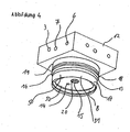
- This figure is intended to clarify the function with regard to freedom from dead space and easier interchangeability of the membrane. This construction is preferred for interchangeable membranes with plastic pressure pipes.
- the liquid is supplied to port (3).
- the liquid or else the gas flow via the outlet bore with annular gap (13) flowing around outside of the receiving cylinder (17) of the membrane into the liquid channels (50) on the outside of the cylinder evenly distributed in the annular gap (21).
- the filtrate is filtered to the permeate collection tube (44) and leaves the functional / connection unit (11) via the filtrate connection (7).
- the retentate exit occurs at the front (45).
- the retentate leaves the function / connection unit via the retentate connection (6).
- liquid outlet (45) can take place on the entire end face, the receiving cylinder of the membrane (17) on its inside a stop (52) on which the membrane is supported on the peripheral edge.
- the special embodiment provides a screwed on pressure tube (4), which is fastened by means of internal thread (23) on the function / connection unit.
- a tube sleeve can be pressed over the outside of the module tube (not shown) in the threaded area.
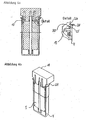
- This figure is intended to clarify the function in terms of dead space and easier interchangeability of the membrane when using metallic pressure pipes.
- a threaded fastener is as in Fig. 5 not described possible. Therefore, the attachment of the pressure tube to the function / connection unit at the bead of the pressure tube (25).
- the flanged edge of the module tube is received by means of a split flange clamp (24) and clamped with the function / connection unit.
- the upper side of the flange clamp (24) lies in a retaining groove (26) of the functional / connection unit (11).
- the flange clamp (24) can consist of 2 semicircles or more circular segments. However, it can also consist of a clamp with one-sided screw.
- the lying on the function / connection unit in the retaining groove (26) side has a larger contact surface than the surface at the bead, since the function / connection unit (11) usually off Plastic and therefore does not have the same strength as the metallic pressure tube.
- the flange 25 tends to buckle, therefore, the flange crimped outwardly at an angle to the module tube may receive an additional angled cuff in alignment with the module tube. This seen from the Modulrohrwandung Z-shape stiffens the flange.
- the connection between the module tube 4 and the functional connection unit 11 can be made by means of a circular-section flange plate and connecting screws.
- This figure is intended to illustrate the function when using a disposable pressure tube with integrated membrane as a low-cost variant.
- the module tube (4) with weld (29) is permanently attached to the lower part (28).
- the liquid is supplied as in Fig. 5 described. Since due to the different thread tolerances of the screw connection (30) between the upper and lower part of the function / connection unit (11), consisting of (27) and (28), the vertical axes of the liquid holes (3 and 6) are not aligned, is by means of Freistich a collection channel for the retentate (34) [formed as a circular ring depression of the second stage of the lower part (55)] and by means of undercut a collecting channel of the feeding liquid (35) [formed as a circular ring depression of the first stage of the lower part (54)] formed.
- an additional retentate effluent channel (36) can be added in the upper part (27) or used as the sole effluent channel.
- an additional flow channel (37) in the upper part (27) can be added to the flow channel (35) or used as the sole flow channel.
- the seal to the individual liquid channels is made with sealing elements (31/32/33).
- the upper part (27) is designed in three stages (54/55/56) or five stages (54/55/56/57/58).
- This figure shows the simple possibility of removal to a filter system of parallel design with standardized components and low production costs.
- this illustration shows in perspective the parallel alignment of the functional / terminal units (11), in this case the prismatic upper part (27).
- the adjacent function / connection units are plugged together by means of connecting plug nipple (42).
- the connecting nipple (42) receive circumferentially sealing elements (53) which are inserted one or more times in succession in the groove (47).
- the latches (43) are inserted over the openings for receiving the lock (41) of the function / connection units.
- the mounting holes (3/7/6) can be mounted simultaneously on all sides of the prismatic top to allow parallel or serial switching to increase the filtrate capacity.
- the flow channels 3,6,7 are connected by means of plug nipple 42 as shown. Due to different demands on the Permeat21, the efficiency of the entire system or the quality of the incoming liquid is also a series circuit or the combination of parallel and serial circuit of the filter elements into consideration, as from FIG. 3 can be seen ..
- the function / connection units receive the connections 3, 6, 7 at one or more sides, which are structurally favorable for the interconnection.
- the individual sections of the flange clamp are to be connected. 25th Modulrohrflansch 26th Holding the flange clamp in the function / connection unit 27th Separate prismatic upper part of the two-part function / connection unit 28th Separate cylindrical lower part of the two-part function / connection unit 29th Weld seam of the permanent module tube 30th Screw connection between upper u.
Claims (14)
- Module de filtre avec un tube de pression et une membrane qui y est agencée, avec des raccords pour un fluide à amener, de préférence de l'eau brute, et pour filtrat et retentat à évacuer, avec une unité de fonctionnement/raccordement (11) qui est fixée à une extrémité du tube de pression (4) et présente une partie supérieure (12) et une partie inférieure,
dans lequel tous les raccords (3, 6, 7) sont prévus au niveau de la partie supérieure (12) et des canaux d'écoulement communiquant avec les raccords (3, 6, 7) traversent la partie inférieure,
dans lequel un espace annulaire (21) ouvert est prévu entre le tube de pression (4) et la membrane (5), par lequel le fluide amené s'écoule vers la face inférieure de la membrane (5), et
dans lequel le tube de pression (4) présente un fond fermé,
caractérisé
en ce que la partie supérieure (12) a une forme de prisme et
en ce que respectivement tous les trois raccords (3, 6, 7) sont prévus dans plusieurs faces latérales du prisme de telle sorte que deux ou plusieurs unités de fonctionnement/raccordement (11) peuvent être reliées les unes aux autres en un système de filtre, dans lequel leurs faces latérales sont parallèles l'une à l'autre, dans lequel les raccords non nécessaires peuvent être obturés à l'aide d'un raccord fileté non percé. - Module de filtre selon la revendication 1,
caractérisé en ce que
l'unité de fonctionnement/raccordement (11) est fixée à l'extrémité supérieure du tube de pression (4). - Module de filtre selon la revendication 1,
caractérisé en ce que
l'unité de fonctionnement/raccordement (11) est fixée à l'extrémité inférieure du tube de pression (4). - Module de filtre selon l'une quelconque des revendications 1 à 3,
caractérisé en ce que
des unités de fonctionnement/raccordement (11) adjacentes peuvent être reliées par des raccords filetés enfichables (42). - Module de filtre selon la revendication 4,
caractérisé en ce que
les raccords filetés enfichables (42) sont verrouillables. - Module de filtre selon l'une quelconque des revendications 1 à 5,
caractérisé en ce que
la partie inférieure a une forme de cylindre et présente un raccord de connexion pour le tube de pression (4) et un raccord (52) pour la membrane (5) de telle sorte que le fluide amené est introduit entre la membrane (5) et la paroi intérieure du tube de pression (4). - Module de filtre selon l'une quelconque des revendications 1 à 6,
caractérisé en ce que
l'unité de fonctionnement/raccordement (11) présente en outre des raccords d'amenée et d'évacuation, qui servent au raccordement du système à des dispositifs externes, au prélèvement d'échantillons ou à l'injection d'agents, qui sont disposés sur les faces latérales ou la face avant de la partie supérieure (12). - Module de filtre selon l'une quelconque des revendications 1 à 7,
caractérisé en ce que
l'unité de fonctionnement/raccordement (11) présente des raccords de réception supplémentaires pour des dispositifs techniques de mesure et de régulation tels des capteurs de mesure de paramètres d'état, débits et propriétés de substances et/ou des dispositifs influençant les flux de gaz/liquide au sens de libération, accélération, blocage, étranglement ou commutation. - Module de filtre selon l'une quelconque des revendications 1 à 8,
caractérisé en ce que
le tube de pression (4) présente un collet (25) et est fixé à la partie inférieure de l'unité de fonctionnement/raccordement (11) à l'aide d'agrafes (24). - Module de filtre selon l'une quelconque des revendications 1 à 8,
caractérisé en ce que
le tube de pression (4) présente un filetage (23) et est fixé à la partie inférieure de l'unité de fonctionnement/raccordement (11) par vissage. - Module de filtre selon l'une quelconque des revendications 1 à 10,
caractérisé en ce que
la partie supérieure (27) et inférieure (28) de l'unité de fonctionnement/raccordement (11) sont fixées l'une à l'autre de manière amovible par vissage. - Module de filtre selon la revendication 11,
caractérisé en ce que
le tube de pression (4) et la membrane (5) sont reliés de manière inamovible à la partie inférieure (28) à visser. - Module de filtre selon la revendication 11,
caractérisé en ce que
la partie supérieure de l'unité de fonctionnement/raccordement (11) a un perçage central à trois niveaux permettant de recevoir la partie inférieure à visser. - Module de filtre selon l'une quelconque des revendications 1 à 13,
caractérisé en ce que
le fond, opposé à l'unité de fonctionnement/ raccordement (11), du tube de pression (4) doit être ouvert.
Priority Applications (2)
| Application Number | Priority Date | Filing Date | Title |
|---|---|---|---|
| PL08801110T PL2190561T3 (pl) | 2007-09-20 | 2008-07-24 | Moduł filtra i jego zestawienie w system filtracyjny |
| EP11000605.3A EP2319611B1 (fr) | 2007-09-20 | 2008-07-24 | Module de filtre avec un bloc de distribution |
Applications Claiming Priority (2)
| Application Number | Priority Date | Filing Date | Title |
|---|---|---|---|
| DE102007044922A DE102007044922B4 (de) | 2007-09-20 | 2007-09-20 | Filtermodul und dessen Aneinanderreihung zu einem Filtersystem |
| PCT/DE2008/001272 WO2009036717A2 (fr) | 2007-09-20 | 2008-07-24 | Module de filtre et empilement de ces modules en un système de filtre |
Related Child Applications (1)
| Application Number | Title | Priority Date | Filing Date |
|---|---|---|---|
| EP11000605.3A Division EP2319611B1 (fr) | 2007-09-20 | 2008-07-24 | Module de filtre avec un bloc de distribution |
Publications (2)
| Publication Number | Publication Date |
|---|---|
| EP2190561A2 EP2190561A2 (fr) | 2010-06-02 |
| EP2190561B1 true EP2190561B1 (fr) | 2011-02-09 |
Family
ID=40120108
Family Applications (2)
| Application Number | Title | Priority Date | Filing Date |
|---|---|---|---|
| EP08801110A Not-in-force EP2190561B1 (fr) | 2007-09-20 | 2008-07-24 | Module de filtre et empilement de ces modules en un système de filtre |
| EP11000605.3A Active EP2319611B1 (fr) | 2007-09-20 | 2008-07-24 | Module de filtre avec un bloc de distribution |
Family Applications After (1)
| Application Number | Title | Priority Date | Filing Date |
|---|---|---|---|
| EP11000605.3A Active EP2319611B1 (fr) | 2007-09-20 | 2008-07-24 | Module de filtre avec un bloc de distribution |
Country Status (12)
| Country | Link |
|---|---|
| US (1) | US9162187B2 (fr) |
| EP (2) | EP2190561B1 (fr) |
| CN (1) | CN101855006B (fr) |
| AT (1) | ATE497832T1 (fr) |
| BR (1) | BRPI0815969B1 (fr) |
| DE (2) | DE102007044922B4 (fr) |
| ES (2) | ES2533430T3 (fr) |
| MX (1) | MX2010003127A (fr) |
| PL (1) | PL2190561T3 (fr) |
| PT (1) | PT2190561E (fr) |
| RU (1) | RU2455053C2 (fr) |
| WO (1) | WO2009036717A2 (fr) |
Families Citing this family (19)
| Publication number | Priority date | Publication date | Assignee | Title |
|---|---|---|---|---|
| US20110120928A1 (en) * | 2009-11-25 | 2011-05-26 | Watts Water Technologies, Inc. | Easy change filter assembly for reverse osmosis membrane water purification system |
| DE102010009816B4 (de) * | 2010-03-02 | 2016-11-24 | Manfred Völker | Fluidsystem zur Versorgung eines Gerätes mit hochreiner Flüssigkeit |
| ITME20110001A1 (it) * | 2011-01-28 | 2012-07-29 | Terminter Srl | Sistema nuova osmosi |
| NL2006101C2 (nl) * | 2011-01-31 | 2012-08-01 | Artemis Systems B V | Inrichting voor het zuiveren van ruw water. |
| DE102011006543A1 (de) * | 2011-03-31 | 2012-10-04 | Krones Aktiengesellschaft | Membranfitrationsmodul |
| DE102011109093A1 (de) * | 2011-08-01 | 2013-02-07 | Manfred Völker | Kombination eines Einzelplatz-RO-Gerätes mit einem Hämodialysegerät |
| DE102012006320A1 (de) * | 2012-03-28 | 2013-10-02 | Manfred Völker | Membrane für Umkehrosmose |
| DE102012213483A1 (de) * | 2012-07-31 | 2014-02-06 | Krones Ag | Membranelement, Membranmodul und Membranverbindung |
| US20140069856A1 (en) * | 2012-09-13 | 2014-03-13 | Ying-Chen Lin | Water gathering cover |
| EP2907565A1 (fr) * | 2014-02-17 | 2015-08-19 | Bayer Technology Services GmbH | Unité de dialyse pour le changement continu de tampons ou de fluides à partir d'une solution protéique |
| WO2016074630A1 (fr) * | 2014-11-14 | 2016-05-19 | 天纳克(苏州)排放系统有限公司 | Ensemble filtre |
| ES2720280T3 (es) | 2015-02-05 | 2019-07-19 | Holger Knappe | Cabezal de distribución modular para cuerpo de carcasa de membrana |
| CN107096386A (zh) * | 2016-02-19 | 2017-08-29 | 上海奥星制药技术装备有限公司 | 反渗透膜壳体 |
| US11002373B2 (en) | 2017-01-13 | 2021-05-11 | Bwt Aqua Ag | Device and method of preparing salt-containing water by reverse osmosis |
| EP3473329A1 (fr) * | 2017-10-19 | 2019-04-24 | 3M Innovative Properties Company | Bâti de module à membrane intégrée |
| EP4142910A4 (fr) | 2020-04-28 | 2024-04-24 | Entegris Inc | Collecteur de filtre modulaire |
| WO2022106432A1 (fr) | 2020-11-18 | 2022-05-27 | Zhejiang Qinyuan Water Treatment S. T. Co., Ltd. | Unité de filtre à membrane |
| USD981531S1 (en) * | 2021-03-24 | 2023-03-21 | LANG Beverages SA | Water filter |
| CN113368565B (zh) * | 2021-06-30 | 2022-07-19 | 吉林信达石油技术服务有限公司 | 一种石油压裂液废水预处理装置 |
Family Cites Families (27)
| Publication number | Priority date | Publication date | Assignee | Title |
|---|---|---|---|---|
| US4476015A (en) * | 1982-11-02 | 1984-10-09 | V. J. Ciccone & Associates, Inc. | Multiple element fluid separation device |
| JPS63163002A (ja) * | 1986-12-26 | 1988-07-06 | Kuroda Precision Ind Ltd | 流体制御要素の連結ユニツト |
| DE3943631C2 (en) * | 1989-05-20 | 1992-10-29 | Seitz-Filter-Werke Theo & Geo Seitz Gmbh Und Co, 6550 Bad Kreuznach, De | Cross-flow liq. filtration by hollow membranes |
| EP0447513B1 (fr) * | 1989-09-29 | 1997-01-29 | Memtec Limited | Collecteur pour cartouches filtrantes |
| US5221473A (en) * | 1989-10-13 | 1993-06-22 | Burrows Bruce D | Filter cartridge assembly for a reverse osmosis purification system |
| US5354464A (en) * | 1990-03-14 | 1994-10-11 | Water Factory Systems | Multi-port connecting device |
| US5128035A (en) * | 1990-03-15 | 1992-07-07 | Clack Corporation | Fluid flow control device for water treatment systems |
| ES2126571T3 (es) * | 1990-04-20 | 1999-04-01 | Usf Filtration Limited | Conjuntos de filtros modulares microporosos. |
| US5389260A (en) * | 1993-04-02 | 1995-02-14 | Clack Corporation | Brine seal for tubular filter |
| DE9422466U1 (de) * | 1993-07-09 | 2003-01-30 | Parker Hannifin Corp | Lösbarer Verbinder für Druckfluidbauteile |
| US5401399A (en) * | 1993-08-27 | 1995-03-28 | Magnusson; Jan H. | Water purification system |
| US5865996A (en) * | 1996-08-14 | 1999-02-02 | Reid; Roger P. | Water purifier with collet and tube support |
| JP2001149933A (ja) * | 1999-11-29 | 2001-06-05 | Nitto Denko Corp | 逆浸透膜型カートリッジポリッシャー |
| US6436282B1 (en) * | 2000-08-08 | 2002-08-20 | Plymouth Products, Inc. | Flow control module for RO water treatment system |
| EP1219342B1 (fr) * | 2000-12-22 | 2003-05-28 | Grünbeck Wasseraufbereitung GmbH | Dispositif de traitement de liquides |
| RU23140U1 (ru) * | 2001-03-01 | 2002-05-27 | Ставропольская Государственная Сельскохозяйственная Академия | Мембранный аппарат |
| US7604738B2 (en) * | 2002-02-08 | 2009-10-20 | Schroeder Industries Llc | Connecting end cap for a filter |
| US6740235B2 (en) * | 2002-03-04 | 2004-05-25 | Culligan International Company | Swivelling filter head assembly |
| FR2840451B1 (fr) * | 2002-06-04 | 2004-08-13 | Centre Nat Rech Scient | Dispositif de production d'une nappe de plasma |
| AU2003245485A1 (en) * | 2002-06-12 | 2003-12-31 | The Water System Group, Inc. | Purified water supply system |
| FR2845082B1 (fr) * | 2002-09-26 | 2006-02-10 | Millipore Corp | Module de purification d'un fluide, notamment d'eau |
| US7017611B2 (en) * | 2003-02-04 | 2006-03-28 | Watts Regulator C. | One-piece manifold for a reverse osmosis system |
| AU2004268929A1 (en) * | 2003-05-02 | 2005-03-10 | 3M Innovative Properties Company | Crossflow filtration system with quick dry change elements |
| US7294262B2 (en) * | 2003-08-27 | 2007-11-13 | Sta-Rite Industries, Llc | Modular fluid treatment apparatus |
| IN2012DN00889A (fr) * | 2005-01-27 | 2015-07-10 | Ecowater Systems Llc | |
| KR100712266B1 (ko) * | 2005-03-24 | 2007-05-17 | 주식회사 피코그램 | 커넥터를 이용하여 용이하게 교체되는 정수용 필터, 및 이를 이용한 정수장치 |
| DE102005052486A1 (de) * | 2005-11-03 | 2007-05-10 | Asana Ro-Wasserbehandlung Gmbh | Filtereinrichtung |
-
2007
- 2007-09-20 DE DE102007044922A patent/DE102007044922B4/de active Active
-
2008
- 2008-07-24 EP EP08801110A patent/EP2190561B1/fr not_active Not-in-force
- 2008-07-24 DE DE502008002576T patent/DE502008002576D1/de active Active
- 2008-07-24 WO PCT/DE2008/001272 patent/WO2009036717A2/fr active Application Filing
- 2008-07-24 EP EP11000605.3A patent/EP2319611B1/fr active Active
- 2008-07-24 AT AT08801110T patent/ATE497832T1/de active
- 2008-07-24 MX MX2010003127A patent/MX2010003127A/es active IP Right Grant
- 2008-07-24 US US12/679,094 patent/US9162187B2/en active Active
- 2008-07-24 ES ES11000605.3T patent/ES2533430T3/es active Active
- 2008-07-24 PL PL08801110T patent/PL2190561T3/pl unknown
- 2008-07-24 RU RU2010115478/05A patent/RU2455053C2/ru active
- 2008-07-24 CN CN200880115639.7A patent/CN101855006B/zh active Active
- 2008-07-24 PT PT08801110T patent/PT2190561E/pt unknown
- 2008-07-24 BR BRPI0815969A patent/BRPI0815969B1/pt active IP Right Grant
- 2008-07-24 ES ES08801110T patent/ES2360163T3/es active Active
Also Published As
| Publication number | Publication date |
|---|---|
| DE102007044922A1 (de) | 2009-04-09 |
| ES2533430T3 (es) | 2015-04-10 |
| EP2319611B1 (fr) | 2015-01-07 |
| US9162187B2 (en) | 2015-10-20 |
| PT2190561E (pt) | 2011-05-12 |
| US20100307965A1 (en) | 2010-12-09 |
| DE502008002576D1 (de) | 2011-03-24 |
| BRPI0815969A2 (pt) | 2018-02-14 |
| WO2009036717A3 (fr) | 2009-06-18 |
| PL2190561T3 (pl) | 2011-07-29 |
| RU2455053C2 (ru) | 2012-07-10 |
| DE102007044922B4 (de) | 2012-04-19 |
| WO2009036717A2 (fr) | 2009-03-26 |
| BRPI0815969B1 (pt) | 2020-02-04 |
| EP2190561A2 (fr) | 2010-06-02 |
| ES2360163T3 (es) | 2011-06-01 |
| EP2319611A1 (fr) | 2011-05-11 |
| ATE497832T1 (de) | 2011-02-15 |
| CN101855006A (zh) | 2010-10-06 |
| CN101855006B (zh) | 2015-12-16 |
| RU2010115478A (ru) | 2011-10-27 |
| MX2010003127A (es) | 2010-09-09 |
Similar Documents
| Publication | Publication Date | Title |
|---|---|---|
| EP2190561B1 (fr) | Module de filtre et empilement de ces modules en un système de filtre | |
| EP1251944B1 (fr) | Dispositif et installation pour la filtration a contre-courant | |
| DE3916511A1 (de) | Membranfiltervorrichtung zur mikro- und ultrafiltration von fluiden im crossflow-verfahren | |
| DE3317517C2 (de) | Vorrichtung zum Filtern und Trennen von flüssigen und gasförmigen Medien | |
| DE602005002206T2 (de) | Anschlussadapter für eine Tangentialfiltrationscassette | |
| DE102006022502A1 (de) | Filtereinheit für die Abwasseraufbereitung und die Trinkwassergewinnung | |
| EP1812147A1 (fr) | Dispositif pour eliminer par filtrage des substances contenues dans des liquides | |
| DE602004013309T2 (de) | Apparat zur trennung eines fluides in mindestens zwei fraktionen mittels einer vielzahl von membranen sowie seine verwendung | |
| US20100140153A1 (en) | Manifold block for reverse osmosis systems | |
| EP1842580B1 (fr) | Dispositif destiné au dessalage électrochimique continu avec une étape membranaire intégrée | |
| DE102019132699A1 (de) | Vorrichtung zur Filterung von Bestandteilen aus einem Fluid | |
| EP3241806B1 (fr) | Dispositif de filtre terminal destiné à réduire les impuretés microbiologiques dans un milieu aqueux | |
| EP1747811B1 (fr) | Filtre pour la production d'eau essentiellement exempte de germes | |
| DE2945317A1 (de) | Vorrichtung zur wasserentsalzung und -reinigung durch umgekehrte osmose und ultrafiltration | |
| DE19933223B4 (de) | Verfahren zur thermischen Desinfektion von Hämodialyseanlagen | |
| DE102009031044A1 (de) | Anschluss einer sekundären Leitung einer Reinwasser-Hauptversorgungsleitung an ein Dialysegerät oder dergleichen | |
| DE3326704A1 (de) | Verfahren und vorrichtung zur haemodialyse | |
| EP2505257B1 (fr) | Module de filtration sur membranes | |
| EP3053640B1 (fr) | Tête de répartiteur modulaire pour corps de boîtier à membrane | |
| DE3943631C2 (en) | Cross-flow liq. filtration by hollow membranes | |
| EP3810303A1 (fr) | Système de filtration pour processus biopharmaceutiques | |
| DE202022001680U1 (de) | Filtervorrichtung vorgesehen zur Mikro- und/oder Ultrafiltration und/oder zur Fest-Flüssig-Trennung | |
| DE3341642A1 (de) | Aus einem gehaeuse und mindestens einem filterelement bestehende filteranordnung | |
| DE3937689A1 (de) | Verbundreaktor fuer ionenaustauschprozesse zur gewinnung von partikelfreiem deionisiertem wasser |
Legal Events
| Date | Code | Title | Description |
|---|---|---|---|
| PUAI | Public reference made under article 153(3) epc to a published international application that has entered the european phase |
Free format text: ORIGINAL CODE: 0009012 |
|
| 17P | Request for examination filed |
Effective date: 20100327 |
|
| AK | Designated contracting states |
Kind code of ref document: A2 Designated state(s): AT BE BG CH CY CZ DE DK EE ES FI FR GB GR HR HU IE IS IT LI LT LU LV MC MT NL NO PL PT RO SE SI SK TR |
|
| AX | Request for extension of the european patent |
Extension state: AL BA MK RS |
|
| GRAP | Despatch of communication of intention to grant a patent |
Free format text: ORIGINAL CODE: EPIDOSNIGR1 |
|
| GRAS | Grant fee paid |
Free format text: ORIGINAL CODE: EPIDOSNIGR3 |
|
| GRAA | (expected) grant |
Free format text: ORIGINAL CODE: 0009210 |
|
| AK | Designated contracting states |
Kind code of ref document: B1 Designated state(s): AT BE BG CH CY CZ DE DK EE ES FI FR GB GR HR HU IE IS IT LI LT LU LV MC MT NL NO PL PT RO SE SI SK TR |
|
| REG | Reference to a national code |
Ref country code: GB Ref legal event code: FG4D Free format text: NOT ENGLISH |
|
| REG | Reference to a national code |
Ref country code: CH Ref legal event code: EP |
|
| REG | Reference to a national code |
Ref country code: IE Ref legal event code: FG4D Free format text: LANGUAGE OF EP DOCUMENT: GERMAN |
|
| REF | Corresponds to: |
Ref document number: 502008002576 Country of ref document: DE Date of ref document: 20110324 Kind code of ref document: P |
|
| REG | Reference to a national code |
Ref country code: DE Ref legal event code: R096 Ref document number: 502008002576 Country of ref document: DE Effective date: 20110324 |
|
| REG | Reference to a national code |
Ref country code: CH Ref legal event code: NV Representative=s name: KIRKER & CIE S.A. |
|
| REG | Reference to a national code |
Ref country code: PT Ref legal event code: SC4A Free format text: AVAILABILITY OF NATIONAL TRANSLATION Effective date: 20110505 |
|
| REG | Reference to a national code |
Ref country code: NL Ref legal event code: VDEP Effective date: 20110209 Ref country code: ES Ref legal event code: FG2A Ref document number: 2360163 Country of ref document: ES Kind code of ref document: T3 Effective date: 20110601 |
|
| LTIE | Lt: invalidation of european patent or patent extension |
Effective date: 20110209 |
|
| PG25 | Lapsed in a contracting state [announced via postgrant information from national office to epo] |
Ref country code: HR Free format text: LAPSE BECAUSE OF FAILURE TO SUBMIT A TRANSLATION OF THE DESCRIPTION OR TO PAY THE FEE WITHIN THE PRESCRIBED TIME-LIMIT Effective date: 20110209 Ref country code: LV Free format text: LAPSE BECAUSE OF FAILURE TO SUBMIT A TRANSLATION OF THE DESCRIPTION OR TO PAY THE FEE WITHIN THE PRESCRIBED TIME-LIMIT Effective date: 20110209 Ref country code: GR Free format text: LAPSE BECAUSE OF FAILURE TO SUBMIT A TRANSLATION OF THE DESCRIPTION OR TO PAY THE FEE WITHIN THE PRESCRIBED TIME-LIMIT Effective date: 20110510 Ref country code: NO Free format text: LAPSE BECAUSE OF FAILURE TO SUBMIT A TRANSLATION OF THE DESCRIPTION OR TO PAY THE FEE WITHIN THE PRESCRIBED TIME-LIMIT Effective date: 20110509 Ref country code: LT Free format text: LAPSE BECAUSE OF FAILURE TO SUBMIT A TRANSLATION OF THE DESCRIPTION OR TO PAY THE FEE WITHIN THE PRESCRIBED TIME-LIMIT Effective date: 20110209 Ref country code: SE Free format text: LAPSE BECAUSE OF FAILURE TO SUBMIT A TRANSLATION OF THE DESCRIPTION OR TO PAY THE FEE WITHIN THE PRESCRIBED TIME-LIMIT Effective date: 20110209 |
|
| REG | Reference to a national code |
Ref country code: PL Ref legal event code: T3 |
|
| PG25 | Lapsed in a contracting state [announced via postgrant information from national office to epo] |
Ref country code: FI Free format text: LAPSE BECAUSE OF FAILURE TO SUBMIT A TRANSLATION OF THE DESCRIPTION OR TO PAY THE FEE WITHIN THE PRESCRIBED TIME-LIMIT Effective date: 20110209 Ref country code: NL Free format text: LAPSE BECAUSE OF FAILURE TO SUBMIT A TRANSLATION OF THE DESCRIPTION OR TO PAY THE FEE WITHIN THE PRESCRIBED TIME-LIMIT Effective date: 20110209 Ref country code: CY Free format text: LAPSE BECAUSE OF FAILURE TO SUBMIT A TRANSLATION OF THE DESCRIPTION OR TO PAY THE FEE WITHIN THE PRESCRIBED TIME-LIMIT Effective date: 20110209 Ref country code: BG Free format text: LAPSE BECAUSE OF FAILURE TO SUBMIT A TRANSLATION OF THE DESCRIPTION OR TO PAY THE FEE WITHIN THE PRESCRIBED TIME-LIMIT Effective date: 20110509 |
|
| REG | Reference to a national code |
Ref country code: IE Ref legal event code: FD4D |
|
| REG | Reference to a national code |
Ref country code: HU Ref legal event code: AG4A Ref document number: E011021 Country of ref document: HU |
|
| PG25 | Lapsed in a contracting state [announced via postgrant information from national office to epo] |
Ref country code: EE Free format text: LAPSE BECAUSE OF FAILURE TO SUBMIT A TRANSLATION OF THE DESCRIPTION OR TO PAY THE FEE WITHIN THE PRESCRIBED TIME-LIMIT Effective date: 20110209 Ref country code: DK Free format text: LAPSE BECAUSE OF FAILURE TO SUBMIT A TRANSLATION OF THE DESCRIPTION OR TO PAY THE FEE WITHIN THE PRESCRIBED TIME-LIMIT Effective date: 20110209 Ref country code: IE Free format text: LAPSE BECAUSE OF FAILURE TO SUBMIT A TRANSLATION OF THE DESCRIPTION OR TO PAY THE FEE WITHIN THE PRESCRIBED TIME-LIMIT Effective date: 20110209 |
|
| PG25 | Lapsed in a contracting state [announced via postgrant information from national office to epo] |
Ref country code: SK Free format text: LAPSE BECAUSE OF FAILURE TO SUBMIT A TRANSLATION OF THE DESCRIPTION OR TO PAY THE FEE WITHIN THE PRESCRIBED TIME-LIMIT Effective date: 20110209 Ref country code: RO Free format text: LAPSE BECAUSE OF FAILURE TO SUBMIT A TRANSLATION OF THE DESCRIPTION OR TO PAY THE FEE WITHIN THE PRESCRIBED TIME-LIMIT Effective date: 20110209 |
|
| PGFP | Annual fee paid to national office [announced via postgrant information from national office to epo] |
Ref country code: CZ Payment date: 20110718 Year of fee payment: 4 |
|
| PLBE | No opposition filed within time limit |
Free format text: ORIGINAL CODE: 0009261 |
|
| STAA | Information on the status of an ep patent application or granted ep patent |
Free format text: STATUS: NO OPPOSITION FILED WITHIN TIME LIMIT |
|
| PG25 | Lapsed in a contracting state [announced via postgrant information from national office to epo] |
Ref country code: MT Free format text: LAPSE BECAUSE OF FAILURE TO SUBMIT A TRANSLATION OF THE DESCRIPTION OR TO PAY THE FEE WITHIN THE PRESCRIBED TIME-LIMIT Effective date: 20110209 |
|
| 26N | No opposition filed |
Effective date: 20111110 |
|
| BERE | Be: lapsed |
Owner name: VOLKER, MANFRED Effective date: 20110731 |
|
| PG25 | Lapsed in a contracting state [announced via postgrant information from national office to epo] |
Ref country code: MC Free format text: LAPSE BECAUSE OF NON-PAYMENT OF DUE FEES Effective date: 20110731 |
|
| REG | Reference to a national code |
Ref country code: DE Ref legal event code: R097 Ref document number: 502008002576 Country of ref document: DE Effective date: 20111110 |
|
| PG25 | Lapsed in a contracting state [announced via postgrant information from national office to epo] |
Ref country code: BE Free format text: LAPSE BECAUSE OF NON-PAYMENT OF DUE FEES Effective date: 20110731 |
|
| REG | Reference to a national code |
Ref country code: PT Ref legal event code: MM4A Free format text: LAPSE DUE TO NON-PAYMENT OF FEES Effective date: 20120424 |
|
| PG25 | Lapsed in a contracting state [announced via postgrant information from national office to epo] |
Ref country code: SI Free format text: LAPSE BECAUSE OF FAILURE TO SUBMIT A TRANSLATION OF THE DESCRIPTION OR TO PAY THE FEE WITHIN THE PRESCRIBED TIME-LIMIT Effective date: 20110209 |
|
| PG25 | Lapsed in a contracting state [announced via postgrant information from national office to epo] |
Ref country code: PT Free format text: LAPSE BECAUSE OF NON-PAYMENT OF DUE FEES Effective date: 20120424 |
|
| PGFP | Annual fee paid to national office [announced via postgrant information from national office to epo] |
Ref country code: HU Payment date: 20120808 Year of fee payment: 5 |
|
| GBPC | Gb: european patent ceased through non-payment of renewal fee |
Effective date: 20120724 |
|
| PG25 | Lapsed in a contracting state [announced via postgrant information from national office to epo] |
Ref country code: GB Free format text: LAPSE BECAUSE OF NON-PAYMENT OF DUE FEES Effective date: 20120724 |
|
| PG25 | Lapsed in a contracting state [announced via postgrant information from national office to epo] |
Ref country code: LU Free format text: LAPSE BECAUSE OF NON-PAYMENT OF DUE FEES Effective date: 20110724 |
|
| PG25 | Lapsed in a contracting state [announced via postgrant information from national office to epo] |
Ref country code: IS Free format text: LAPSE BECAUSE OF FAILURE TO SUBMIT A TRANSLATION OF THE DESCRIPTION OR TO PAY THE FEE WITHIN THE PRESCRIBED TIME-LIMIT Effective date: 20110209 |
|
| PG25 | Lapsed in a contracting state [announced via postgrant information from national office to epo] |
Ref country code: TR Free format text: LAPSE BECAUSE OF FAILURE TO SUBMIT A TRANSLATION OF THE DESCRIPTION OR TO PAY THE FEE WITHIN THE PRESCRIBED TIME-LIMIT Effective date: 20110209 |
|
| PG25 | Lapsed in a contracting state [announced via postgrant information from national office to epo] |
Ref country code: CZ Free format text: LAPSE BECAUSE OF NON-PAYMENT OF DUE FEES Effective date: 20130724 Ref country code: HU Free format text: LAPSE BECAUSE OF NON-PAYMENT OF DUE FEES Effective date: 20130725 |
|
| PGFP | Annual fee paid to national office [announced via postgrant information from national office to epo] |
Ref country code: ES Payment date: 20140627 Year of fee payment: 7 |
|
| REG | Reference to a national code |
Ref country code: AT Ref legal event code: MM01 Ref document number: 497832 Country of ref document: AT Kind code of ref document: T Effective date: 20130724 |
|
| PGFP | Annual fee paid to national office [announced via postgrant information from national office to epo] |
Ref country code: CH Payment date: 20140729 Year of fee payment: 7 Ref country code: DE Payment date: 20140911 Year of fee payment: 7 |
|
| PG25 | Lapsed in a contracting state [announced via postgrant information from national office to epo] |
Ref country code: AT Free format text: LAPSE BECAUSE OF NON-PAYMENT OF DUE FEES Effective date: 20130724 |
|
| PGFP | Annual fee paid to national office [announced via postgrant information from national office to epo] |
Ref country code: PL Payment date: 20140714 Year of fee payment: 7 Ref country code: FR Payment date: 20140623 Year of fee payment: 7 |
|
| PGFP | Annual fee paid to national office [announced via postgrant information from national office to epo] |
Ref country code: IT Payment date: 20140730 Year of fee payment: 7 |
|
| REG | Reference to a national code |
Ref country code: DE Ref legal event code: R119 Ref document number: 502008002576 Country of ref document: DE |
|
| REG | Reference to a national code |
Ref country code: CH Ref legal event code: PL |
|
| PG25 | Lapsed in a contracting state [announced via postgrant information from national office to epo] |
Ref country code: LI Free format text: LAPSE BECAUSE OF NON-PAYMENT OF DUE FEES Effective date: 20150731 Ref country code: DE Free format text: LAPSE BECAUSE OF NON-PAYMENT OF DUE FEES Effective date: 20160202 Ref country code: CH Free format text: LAPSE BECAUSE OF NON-PAYMENT OF DUE FEES Effective date: 20150731 Ref country code: IT Free format text: LAPSE BECAUSE OF NON-PAYMENT OF DUE FEES Effective date: 20150724 |
|
| REG | Reference to a national code |
Ref country code: FR Ref legal event code: ST Effective date: 20160331 |
|
| PG25 | Lapsed in a contracting state [announced via postgrant information from national office to epo] |
Ref country code: FR Free format text: LAPSE BECAUSE OF NON-PAYMENT OF DUE FEES Effective date: 20150731 |
|
| PG25 | Lapsed in a contracting state [announced via postgrant information from national office to epo] |
Ref country code: ES Free format text: LAPSE BECAUSE OF NON-PAYMENT OF DUE FEES Effective date: 20150725 |
|
| PG25 | Lapsed in a contracting state [announced via postgrant information from national office to epo] |
Ref country code: PL Free format text: LAPSE BECAUSE OF NON-PAYMENT OF DUE FEES Effective date: 20150724 |