EP2190561B1 - Filter module and the stringing thereof to form a filter system - Google Patents
Filter module and the stringing thereof to form a filter system Download PDFInfo
- Publication number
- EP2190561B1 EP2190561B1 EP08801110A EP08801110A EP2190561B1 EP 2190561 B1 EP2190561 B1 EP 2190561B1 EP 08801110 A EP08801110 A EP 08801110A EP 08801110 A EP08801110 A EP 08801110A EP 2190561 B1 EP2190561 B1 EP 2190561B1
- Authority
- EP
- European Patent Office
- Prior art keywords
- filter module
- functional
- connection unit
- membrane
- pressure pipe
- Prior art date
- Legal status (The legal status is an assumption and is not a legal conclusion. Google has not performed a legal analysis and makes no representation as to the accuracy of the status listed.)
- Not-in-force
Links
- 239000012528 membrane Substances 0.000 claims abstract description 66
- 239000007788 liquid Substances 0.000 claims abstract description 33
- 239000000706 filtrate Substances 0.000 claims abstract description 14
- XLYOFNOQVPJJNP-UHFFFAOYSA-N water Substances O XLYOFNOQVPJJNP-UHFFFAOYSA-N 0.000 claims abstract description 11
- 239000012530 fluid Substances 0.000 claims abstract 3
- 239000012465 retentate Substances 0.000 claims description 19
- 239000000463 material Substances 0.000 claims description 3
- 230000000903 blocking effect Effects 0.000 claims 1
- 238000007599 discharging Methods 0.000 claims 1
- 238000002347 injection Methods 0.000 claims 1
- 239000007924 injection Substances 0.000 claims 1
- 210000004379 membrane Anatomy 0.000 description 62
- 239000012466 permeate Substances 0.000 description 14
- 238000007789 sealing Methods 0.000 description 14
- 210000002445 nipple Anatomy 0.000 description 9
- 238000001223 reverse osmosis Methods 0.000 description 6
- 238000013461 design Methods 0.000 description 5
- 229910021642 ultra pure water Inorganic materials 0.000 description 4
- 239000012498 ultrapure water Substances 0.000 description 4
- 239000012459 cleaning agent Substances 0.000 description 3
- 239000000645 desinfectant Substances 0.000 description 3
- 230000008439 repair process Effects 0.000 description 3
- 238000004659 sterilization and disinfection Methods 0.000 description 3
- 239000000126 substance Substances 0.000 description 3
- 244000052616 bacterial pathogen Species 0.000 description 2
- 239000011324 bead Substances 0.000 description 2
- 238000004140 cleaning Methods 0.000 description 2
- 238000005516 engineering process Methods 0.000 description 2
- 238000001914 filtration Methods 0.000 description 2
- 235000013305 food Nutrition 0.000 description 2
- 238000001631 haemodialysis Methods 0.000 description 2
- 230000000322 hemodialysis Effects 0.000 description 2
- 238000004519 manufacturing process Methods 0.000 description 2
- 238000005259 measurement Methods 0.000 description 2
- 238000000034 method Methods 0.000 description 2
- 239000004033 plastic Substances 0.000 description 2
- 235000014676 Phragmites communis Nutrition 0.000 description 1
- 239000004952 Polyamide Substances 0.000 description 1
- 239000004760 aramid Substances 0.000 description 1
- 150000004984 aromatic diamines Chemical class 0.000 description 1
- 229920003235 aromatic polyamide Polymers 0.000 description 1
- 230000002146 bilateral effect Effects 0.000 description 1
- 239000007795 chemical reaction product Substances 0.000 description 1
- 239000012141 concentrate Substances 0.000 description 1
- 238000010276 construction Methods 0.000 description 1
- 238000011109 contamination Methods 0.000 description 1
- 238000009295 crossflow filtration Methods 0.000 description 1
- 238000000354 decomposition reaction Methods 0.000 description 1
- 238000007872 degassing Methods 0.000 description 1
- 238000011161 development Methods 0.000 description 1
- 238000009826 distribution Methods 0.000 description 1
- 230000000694 effects Effects 0.000 description 1
- 230000002349 favourable effect Effects 0.000 description 1
- 230000014759 maintenance of location Effects 0.000 description 1
- 239000007769 metal material Substances 0.000 description 1
- 244000005700 microbiome Species 0.000 description 1
- 210000000056 organ Anatomy 0.000 description 1
- 239000011368 organic material Substances 0.000 description 1
- 230000002093 peripheral effect Effects 0.000 description 1
- 229920002647 polyamide Polymers 0.000 description 1
- 229920005597 polymer membrane Polymers 0.000 description 1
- 238000001556 precipitation Methods 0.000 description 1
- 238000002203 pretreatment Methods 0.000 description 1
- 239000000047 product Substances 0.000 description 1
- 230000002787 reinforcement Effects 0.000 description 1
- 230000000717 retained effect Effects 0.000 description 1
- 150000003839 salts Chemical class 0.000 description 1
- 239000008399 tap water Substances 0.000 description 1
- 235000020679 tap water Nutrition 0.000 description 1
- 239000010409 thin film Substances 0.000 description 1
- 238000012546 transfer Methods 0.000 description 1
- 238000009827 uniform distribution Methods 0.000 description 1
Images


Classifications
-
- B—PERFORMING OPERATIONS; TRANSPORTING
- B01—PHYSICAL OR CHEMICAL PROCESSES OR APPARATUS IN GENERAL
- B01D—SEPARATION
- B01D65/00—Accessories or auxiliary operations, in general, for separation processes or apparatus using semi-permeable membranes
-
- B—PERFORMING OPERATIONS; TRANSPORTING
- B01—PHYSICAL OR CHEMICAL PROCESSES OR APPARATUS IN GENERAL
- B01D—SEPARATION
- B01D61/00—Processes of separation using semi-permeable membranes, e.g. dialysis, osmosis or ultrafiltration; Apparatus, accessories or auxiliary operations specially adapted therefor
- B01D61/02—Reverse osmosis; Hyperfiltration ; Nanofiltration
- B01D61/025—Reverse osmosis; Hyperfiltration
-
- B—PERFORMING OPERATIONS; TRANSPORTING
- B01—PHYSICAL OR CHEMICAL PROCESSES OR APPARATUS IN GENERAL
- B01D—SEPARATION
- B01D61/00—Processes of separation using semi-permeable membranes, e.g. dialysis, osmosis or ultrafiltration; Apparatus, accessories or auxiliary operations specially adapted therefor
- B01D61/02—Reverse osmosis; Hyperfiltration ; Nanofiltration
- B01D61/08—Apparatus therefor
-
- B—PERFORMING OPERATIONS; TRANSPORTING
- B01—PHYSICAL OR CHEMICAL PROCESSES OR APPARATUS IN GENERAL
- B01D—SEPARATION
- B01D63/00—Apparatus in general for separation processes using semi-permeable membranes
-
- B—PERFORMING OPERATIONS; TRANSPORTING
- B01—PHYSICAL OR CHEMICAL PROCESSES OR APPARATUS IN GENERAL
- B01D—SEPARATION
- B01D2313/00—Details relating to membrane modules or apparatus
- B01D2313/02—Specific tightening or locking mechanisms
-
- B—PERFORMING OPERATIONS; TRANSPORTING
- B01—PHYSICAL OR CHEMICAL PROCESSES OR APPARATUS IN GENERAL
- B01D—SEPARATION
- B01D2313/00—Details relating to membrane modules or apparatus
- B01D2313/04—Specific sealing means
-
- B—PERFORMING OPERATIONS; TRANSPORTING
- B01—PHYSICAL OR CHEMICAL PROCESSES OR APPARATUS IN GENERAL
- B01D—SEPARATION
- B01D2313/00—Details relating to membrane modules or apparatus
- B01D2313/10—Specific supply elements
-
- B—PERFORMING OPERATIONS; TRANSPORTING
- B01—PHYSICAL OR CHEMICAL PROCESSES OR APPARATUS IN GENERAL
- B01D—SEPARATION
- B01D2313/00—Details relating to membrane modules or apparatus
- B01D2313/10—Specific supply elements
- B01D2313/105—Supply manifolds
-
- B—PERFORMING OPERATIONS; TRANSPORTING
- B01—PHYSICAL OR CHEMICAL PROCESSES OR APPARATUS IN GENERAL
- B01D—SEPARATION
- B01D2313/00—Details relating to membrane modules or apparatus
- B01D2313/12—Specific discharge elements
-
- B—PERFORMING OPERATIONS; TRANSPORTING
- B01—PHYSICAL OR CHEMICAL PROCESSES OR APPARATUS IN GENERAL
- B01D—SEPARATION
- B01D2313/00—Details relating to membrane modules or apparatus
- B01D2313/12—Specific discharge elements
- B01D2313/125—Discharge manifolds
-
- B—PERFORMING OPERATIONS; TRANSPORTING
- B01—PHYSICAL OR CHEMICAL PROCESSES OR APPARATUS IN GENERAL
- B01D—SEPARATION
- B01D2313/00—Details relating to membrane modules or apparatus
- B01D2313/21—Specific headers, end caps
-
- B—PERFORMING OPERATIONS; TRANSPORTING
- B01—PHYSICAL OR CHEMICAL PROCESSES OR APPARATUS IN GENERAL
- B01D—SEPARATION
- B01D2313/00—Details relating to membrane modules or apparatus
- B01D2313/44—Cartridge types
-
- B—PERFORMING OPERATIONS; TRANSPORTING
- B01—PHYSICAL OR CHEMICAL PROCESSES OR APPARATUS IN GENERAL
- B01D—SEPARATION
- B01D2315/00—Details relating to the membrane module operation
- B01D2315/10—Cross-flow filtration
Definitions
- the invention relates to a filter module and its juxtaposition to a filter system.
- the system was conceived and developed as an application in the field of water treatment, especially as part of a reverse osmosis system. However, it is easily applicable to other applications e.g. Transfer gas filtration.
- this filter module consisting of a filter - also called membrane -, a pressure tube and a function / connection unit is designed as a quick-change filter and includes a dead space-free water supply.
- the special design of the filter module provides a closure technique for one-sided connection to a function / connection unit.
- Another feature is the stringing together of several filter modules to a filter system. Of particular importance is that the incoming and outgoing connections to the filter module always one-sided, i. take place at the functional / connection unit.
- Reverse osmosis plants are particularly useful for obtaining pure, germ-free water from tap water, e.g. for medical, pharmaceutical and food applications.
- the ultrapure water thus obtained is ideally germ-free due to the retention properties of the membrane and free of organic decomposition products. In reality, however, this is not necessarily true. Without special countermeasures, colonization of the permeate system with microorganisms can occur. It forms a so-called biofilm on the inner surfaces of the liquid-carrying system. This biofilm is also called fouling.
- Fouling describes the loss of permeate through the attachment of secondary layers on the membrane surface. This may be organic material, colloidal materials or inorganic salts that exceed the precipitation limits upon concentration.
- thermo-resistant polymer membranes for reverse osmosis are available, which are disinfected with water at 90 ° C. This measure initially serves only to reduce germs, but is of little help in removing the biofilm.
- Another possibility is to disinfect or purify reverse osmosis systems at suitable intervals.
- the interrupted normal operation and supplied to the liquid-carrying system, a chemical disinfectant or cleaning agent.
- a suitable exposure time follows a rinsing process, which serves to remove the introduced disinfectant or cleaning agent and its reaction products, so that then the normal supply operation can be resumed.
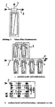
- This membrane exchange is carried out in the existing devices by a technician in such a way that first the entire reverse osmosis system shut down and by means of a tool, the three-piece filter module consisting of membrane element, pressure tube and connection unit is disassembled.
- a conventional structure is in illustration 1 shown.
- Another disadvantage is the exchange following chemical disinfection, which is necessary because during the repair and the high purity components of the connecting pipes or components were contaminated by technicians and tools.
- This aromatic polyamide is applied in an extremely thin layer ( ⁇ 0.3 microns) to a support membrane (or support layer).
- the membrane is therefore also called thin-film membrane.
- Another disadvantage of this technology is that the incoming and outgoing connections to the filter module are bilateral at both ends of the filter module.
- the US-A-5 401 399 discloses a modular cross-flow filtration system with prismatic units having multi-sided feed and permeate connections. The retentate is removed at the opposite end of the pressure tube.
- the JP 63 163002 , the DE 94 22 466 as well as the US-A-5,389,260 disclose modular filter systems with prismatic tops, but have no retentate connections because they are dead-end systems.
- the supplied liquid flows from the supply container (1) via the high-pressure pump (2) and the connection of the liquid supply (3), which is fixed to the cover of the pressure tube (48), via the pressure tube (4) in the membrane (5).
- the annular gap between the membrane and pressure tube inner side (21) is not flowed through because of the sealing lip of the membrane (8).
- a portion of the supplied liquid would lead to an insufficient membrane overflow due to the resulting bypass to the membrane.
- the missing overflow would then have to be compensated with a larger pump capacity.
- Via the filtrate connection (7), which is fastened to the cover (49) the ultrapure water flows to the outlet DP.
- the release valve (39) is opened and the ultrapure water flows back to the flow container (1).
- the Verschventil (9) is switched periodically.
- the module tube (4) in this case receives two covers (48/49), in which on the one hand the connection liquid supply (3) and on the other hand, the terminals for retentate and filtrate (6 and 7) are attached. To disassemble, open the covers (48/49). Before the connections (3/6/7) - which are usually designed as a high-pressure-resistant connection to solve. Only then can the Membrane to be removed. Because of the many leaks, frequent leaks are the result of repairs.
- FIG. 1 shows the scheme of the functional / connection unit (11) according to the invention.
- all 3 connections (3/7/6) are supplied on one side, ie at one end of the module tube, and that the annular gap between membrane and pressure tube inner side (21) is flushed through.
- This figure illustrates the scheme and, in particular, shows the possibility of modular serial and parallel switching to increase the filtrate capacity.
- This enlargement can be achieved by juxtaposing and connecting the function / connection unit (11). High-pressure connections are not necessary, as well as the membrane replacement can be performed without disconnection of the lines.
- the unneeded connections by means of connecting nipple 42, which is used here as an undrilled nipple, closed, or not created.
- the advantage lies in the uniform design of the functional / terminal units 11. The flow guidance shown is only possible if the terminals 3 and 6 are arranged symmetrically to the terminal 7 and horizontally also lie on a line so that in serial connection, the following functional / Connection unit can be rotated 180 °.
- connections 3 and 6 are not symmetrical with respect to the connection 7 and if they are not in line with each other, a reversal of the flow direction within the filter module occurs.
- the flow direction shown is advantageous but not mandatory, so that depending on the design advantage, the functional / terminal unit 11 can be performed with symmetrical or unbalanced terminals 3,6,7.
- the function / connection unit may be attached to the upper or lower end of the pressure tube.
- the liquid channels (50) and the webs (51) serve to uniformly distribute the liquid feed into the annular gap between the membrane and the inside of the pressure pipe.
- the membrane stop (52) ensures an unhindered outflow of the retentate into the bore (14).
- the prismatic upper part can additionally contain receiving connections for measuring and control tasks.
- the geometry is particularly useful for the space-saving juxtaposition of multiple units.
- the filtrate port 7 is usually always centered.
- the connections 3, 6 are advantageously symmetrical with respect to FIG. 7 and lie on a common horizontal plane relative to one another. This makes it possible to use the function / connection unit 11 in a filter system in each case by 180 ° to rotate and to string together so that there is no change in direction of the flow within the filter modules. However, it may also be structurally expedient to deviate from this symmetry in order to achieve flow changes within the filter module.
- This figure is intended to clarify the function with regard to freedom from dead space and easier interchangeability of the membrane. This construction is preferred for interchangeable membranes with plastic pressure pipes.
- the liquid is supplied to port (3).
- the liquid or else the gas flow via the outlet bore with annular gap (13) flowing around outside of the receiving cylinder (17) of the membrane into the liquid channels (50) on the outside of the cylinder evenly distributed in the annular gap (21).
- the filtrate is filtered to the permeate collection tube (44) and leaves the functional / connection unit (11) via the filtrate connection (7).
- the retentate exit occurs at the front (45).
- the retentate leaves the function / connection unit via the retentate connection (6).
- liquid outlet (45) can take place on the entire end face, the receiving cylinder of the membrane (17) on its inside a stop (52) on which the membrane is supported on the peripheral edge.
- the special embodiment provides a screwed on pressure tube (4), which is fastened by means of internal thread (23) on the function / connection unit.
- a tube sleeve can be pressed over the outside of the module tube (not shown) in the threaded area.
- This figure is intended to clarify the function in terms of dead space and easier interchangeability of the membrane when using metallic pressure pipes.
- a threaded fastener is as in Fig. 5 not described possible. Therefore, the attachment of the pressure tube to the function / connection unit at the bead of the pressure tube (25).
- the flanged edge of the module tube is received by means of a split flange clamp (24) and clamped with the function / connection unit.
- the upper side of the flange clamp (24) lies in a retaining groove (26) of the functional / connection unit (11).
- the flange clamp (24) can consist of 2 semicircles or more circular segments. However, it can also consist of a clamp with one-sided screw.
- the lying on the function / connection unit in the retaining groove (26) side has a larger contact surface than the surface at the bead, since the function / connection unit (11) usually off Plastic and therefore does not have the same strength as the metallic pressure tube.
- the flange 25 tends to buckle, therefore, the flange crimped outwardly at an angle to the module tube may receive an additional angled cuff in alignment with the module tube. This seen from the Modulrohrwandung Z-shape stiffens the flange.
- the connection between the module tube 4 and the functional connection unit 11 can be made by means of a circular-section flange plate and connecting screws.
- This figure is intended to illustrate the function when using a disposable pressure tube with integrated membrane as a low-cost variant.
- the module tube (4) with weld (29) is permanently attached to the lower part (28).
- the liquid is supplied as in Fig. 5 described. Since due to the different thread tolerances of the screw connection (30) between the upper and lower part of the function / connection unit (11), consisting of (27) and (28), the vertical axes of the liquid holes (3 and 6) are not aligned, is by means of Freistich a collection channel for the retentate (34) [formed as a circular ring depression of the second stage of the lower part (55)] and by means of undercut a collecting channel of the feeding liquid (35) [formed as a circular ring depression of the first stage of the lower part (54)] formed.
- an additional retentate effluent channel (36) can be added in the upper part (27) or used as the sole effluent channel.
- an additional flow channel (37) in the upper part (27) can be added to the flow channel (35) or used as the sole flow channel.
- the seal to the individual liquid channels is made with sealing elements (31/32/33).
- the upper part (27) is designed in three stages (54/55/56) or five stages (54/55/56/57/58).
- This figure shows the simple possibility of removal to a filter system of parallel design with standardized components and low production costs.
- this illustration shows in perspective the parallel alignment of the functional / terminal units (11), in this case the prismatic upper part (27).
- the adjacent function / connection units are plugged together by means of connecting plug nipple (42).
- the connecting nipple (42) receive circumferentially sealing elements (53) which are inserted one or more times in succession in the groove (47).
- the latches (43) are inserted over the openings for receiving the lock (41) of the function / connection units.
- the mounting holes (3/7/6) can be mounted simultaneously on all sides of the prismatic top to allow parallel or serial switching to increase the filtrate capacity.
- the flow channels 3,6,7 are connected by means of plug nipple 42 as shown. Due to different demands on the Permeat21, the efficiency of the entire system or the quality of the incoming liquid is also a series circuit or the combination of parallel and serial circuit of the filter elements into consideration, as from FIG. 3 can be seen ..
- the function / connection units receive the connections 3, 6, 7 at one or more sides, which are structurally favorable for the interconnection.
- the individual sections of the flange clamp are to be connected. 25th Modulrohrflansch 26th Holding the flange clamp in the function / connection unit 27th Separate prismatic upper part of the two-part function / connection unit 28th Separate cylindrical lower part of the two-part function / connection unit 29th Weld seam of the permanent module tube 30th Screw connection between upper u.
Abstract
Description
Die Erfindung betrifft ein Filtermodul und dessen Aneinanderreihung zu einem Filtersystem. Konzipiert und entwickelt wurde das System als Anwendung im Bereich der Wasseraufbereitung, speziell als Bestandteil einer Umkehrosmoseanlage. Es ist jedoch leicht auf andere Anwendungen z.B. Gasfiltration zu übertragen.The invention relates to a filter module and its juxtaposition to a filter system. The system was conceived and developed as an application in the field of water treatment, especially as part of a reverse osmosis system. However, it is easily applicable to other applications e.g. Transfer gas filtration.
Ein wesentlicher Aspekt der Erfindung ist, dass dieses Filtermodul, bestehend aus einem Filter - auch Membrane genannt -, einem Druckrohr und einer Funktions- / Anschlusseinheit als Schnellwechselfilter ausgebildet ist und eine totraumfreie Wasserführung beinhaltet. Die besondere Ausgestaltung des Filtermoduls sieht eine Verschlusstechnik zum einseitigen Anschluss an eine Funktions- / Anschlusseinheit vor. Ein weiteres Merkmal ist die Aneinanderreihung mehrere Filtermodule zu einem Filtersystem. Von besonderer Bedeutung ist dabei, dass die zu- und abführenden Anschlüssen an das Filtermodul immer einseitig, d.h. an der Funktions- / Anschlusseinheit erfolgen.An essential aspect of the invention is that this filter module, consisting of a filter - also called membrane -, a pressure tube and a function / connection unit is designed as a quick-change filter and includes a dead space-free water supply. The special design of the filter module provides a closure technique for one-sided connection to a function / connection unit. Another feature is the stringing together of several filter modules to a filter system. Of particular importance is that the incoming and outgoing connections to the filter module always one-sided, i. take place at the functional / connection unit.
Umkehrosmoseanlagen dienen insbesondere zur Gewinnung von reinem, keimfreiem Wassers aus Leitungswasser, z.B. für medizinische, pharmazeutische und lebensmitteltechnische Anwendungen.Reverse osmosis plants are particularly useful for obtaining pure, germ-free water from tap water, e.g. for medical, pharmaceutical and food applications.
Ihr Funktionsprinzip besteht bekanntlich darin, dass das aufzubereitende Wasser in einem Filtermodul unter Druck an der Oberfläche einer semipermeablen Membran entlang geführt wird, wobei ein Teil des Wassers, das so genannte Permeat, durch die Membran tritt und auf der anderen Seite der Membran als Reinstwasser gesammelt und der Verbrauchsstelle zugeführt wird.Their principle of operation is known to be that the water to be treated is passed in a filter module under pressure on the surface of a semi-permeable membrane along, with a portion of the water, the so-called Permeate, passes through the membrane and collected on the other side of the membrane as ultrapure water and the consumption point is supplied.
Der nicht durch die Membran tretende, mit zurückgehaltenen Stoffen angereicherte Teil des Rohwassers, das so genannte Konzentrat, fließt am Ende der Strömungsstrecke des Primärraumes aus dem Membranmodul aus.The part of the raw water which does not pass through the membrane and is enriched with retained substances, the so-called concentrate, flows out of the membrane module at the end of the flow path of the primary space.
Das so gewonnene Reinstwasser ist im Idealfalle aufgrund der Rückhalteeigenschaften der Membran keimfrei und frei von organischen Zerfallsprodukten. In der Realität trifft dies jedoch nicht ohne weiteres zu. Ohne besondere Gegenmaßnahmen kann es zu einer Besiedlung des Permeatsystems mit Mikroorganismen kommen. Es bildet sich ein so genannter Biofilm auf den Innenflächen des flüssigkeitsführenden Systems. Dieser Biofilm wird auch Fouling genannt.The ultrapure water thus obtained is ideally germ-free due to the retention properties of the membrane and free of organic decomposition products. In reality, however, this is not necessarily true. Without special countermeasures, colonization of the permeate system with microorganisms can occur. It forms a so-called biofilm on the inner surfaces of the liquid-carrying system. This biofilm is also called fouling.
Fouling beschreibt den Verlust an Permeatleistung durch Anlagerung von Sekundärschichten auf der Membranoberfläche. Dies kann organisches Material sein, kolloidale Stoffe oder anorganische Salze, die bei der Aufkonzentrierung die Ausfällungsgrenzen überschreiten.Fouling describes the loss of permeate through the attachment of secondary layers on the membrane surface. This may be organic material, colloidal materials or inorganic salts that exceed the precipitation limits upon concentration.
Es gibt bis heute noch kein allgemein gültiges Rezept, um Fouling zu verhindern. "Low Fouling Membranen" und verbesserte Vorbehandlung sowie bessere Membranreinigungen sind nur unzureichende technischen Möglichkeiten, um Fouling zu kontrollieren.There is still no universal recipe to prevent fouling. "Low fouling membranes" and improved pre-treatment as well as better membrane cleaning are only insufficient technical possibilities to control fouling.
In der Industrie sind zum Beispiel temperaturbeständige Polymermembranen für Umkehrosmosen erhältlich, die bei 90 °C mit Wasser desinfiziert werden. Diese Maßnahme dient zunächst nur der Keimreduzierung, ist jedoch zum Ablösen des Biofilms wenig hilfreich.In the industry, for example, temperature-resistant polymer membranes for reverse osmosis are available, which are disinfected with water at 90 ° C. This measure initially serves only to reduce germs, but is of little help in removing the biofilm.
Eine andere Möglichkeit ist, an Umkehrosmoseanlagen in geeigneten Zeitabständen eine Desinfektion bzw. Reinigung vorzunehmen. Hierzu wird der normale Betrieb unterbrochen und dem flüssigkeitsführenden System ein chemisches Desinfektions- bzw. Reinigungsmittel zugeführt. Nach einer geeigneten Einwirkzeit folgt ein Spülvorgang, der dazu dient, das eingebrachte Desinfektionsmittel bzw. Reinigungsmittel und seine Reaktionsprodukte wieder zu entfernen, so dass anschließend der normale Versorgungsbetrieb wieder aufgenommen werden kann.Another possibility is to disinfect or purify reverse osmosis systems at suitable intervals. For this purpose, the interrupted normal operation and supplied to the liquid-carrying system, a chemical disinfectant or cleaning agent. After a suitable exposure time follows a rinsing process, which serves to remove the introduced disinfectant or cleaning agent and its reaction products, so that then the normal supply operation can be resumed.
Wegen der erheblichen Gefahren, die mit einer unkontrollierten Zufuhr bzw. mit den Rückständen von Desinfektions- bzw. Reinigungsmitteln verbunden sind, insbesondere bei Anwendungen im medizinischen Bereich (Hämodialyse) ist diese Tätigkeit in der Regel mit einem Technikereinsatz verbunden und damit kostenintensiv.Because of the considerable dangers associated with an uncontrolled supply or with the residues of disinfectants or cleaning agents, especially in medical applications (hemodialysis), this activity is usually associated with a technician's deployment and therefore costly.
Weitere Nachteile der bisherigen Lösungen sind der hohe Energieeinsatz bei einer thermischen Desinfektion sowie der Verlust an Permeatleistung wegen des nicht ablösbaren Biofilms.Further disadvantages of the previous solutions are the high energy input in a thermal disinfection and the loss of permeate because of the non-removable biofilm.
Da der Verlust an Permeatleistung oder eine Kontamination mit Keimen oft auch nicht mehr durch aufwändige Reinigungs- u. Desinfektionsmaßnahmen zu kompensieren ist, erfolgt ein Austausch der Membranen.Since the loss of permeate or contamination with germs often no longer complicated by cleaning u. Disinfection is compensated, there is a replacement of the membranes.
Dieser Membrantausch wird bei den heute vorhandenen Geräten durch einen Techniker in der Weise durchgeführt, dass zunächst die gesamte Umkehrosmoseanlage stillgesetzt und mittels Werkzeug das dreiteilige Filtermodul, bestehend aus Membranelement, Druckrohr und Anschlusseinheit, demontiert wird. Ein herkömmlicher Aufbau ist in
Danach wird das wasserbenetzte Membranelement aus dem Druckrohr gezogen und durch ein neues ersetzt. Je nach Größe der Anlage handelt es sich um mehrere Membranelemente.Thereafter, the water wetted membrane element is pulled out of the pressure tube and replaced by a new one. Depending on the size of the system, there are several membrane elements.
Dabei können pro Membranelement mehrere Liter auch kontaminiertes Wasser austreten.Several liters of contaminated water can escape per membrane element.
Die während der Reparatur entstehenden Stillstandszeiten der Umkehrosmoseanlage können dabei erheblich sein und insbesondere im Bereich der Organe unterstützenden Geräte (Hämodialyse) zum großen Nachteil für die Patienten werden.The resulting during the repair downtime of the reverse osmosis system can be considerable and especially in the field of organs supporting devices (hemodialysis) become a major disadvantage for the patients.
Ein weiterer Nachteil ist die dem Austausch folgende chemische Desinfektion, die deshalb erforderlich ist, weil während der Reparatur auch die hochreinen Komponenten der Anschlussrohre bzw. Komponenten durch Techniker und Werkzeug kontaminiert wurden.Another disadvantage is the exchange following chemical disinfection, which is necessary because during the repair and the high purity components of the connecting pipes or components were contaminated by technicians and tools.
Von erheblichem Nachteil ist die historisch bedingte Dreiteiligkeit von Membran, Druckrohr und Anschlusseinheit des vorhandenen Filtermoduls, deren Ursache in den ursprünglich hohen Transmembrandrücken der Membranen begründet ist. Es wurden deshalb Filtermodule mit hoher Druckfestigkeit von Druckrohr und Anschlusseinheit konstruiert.Of considerable disadvantage is the historically caused three-part membrane, pressure tube and connection unit of the existing filter module, the cause of which is due to the originally high transmembrane pressures of the membranes. Therefore filter modules with high pressure resistance of pressure tube and connection unit were constructed.
95% aller RO-Membranen sind heute quervernetzte aromatische Diamine (-Polyamid-).Today, 95% of all RO membranes are cross-linked aromatic diamines (polyamide).
Dieses aromatische Polyamid wird in extrem dünner Schicht (< 0,3 Mikrometer) auf eine Trägermembrane (oder Stützschicht) aufgetragen. Die Membrane wird deshalb auch Dünn-Film-Membrane genannt.This aromatic polyamide is applied in an extremely thin layer (<0.3 microns) to a support membrane (or support layer). The membrane is therefore also called thin-film membrane.
Die immer dünnere Membranschichtentwicklung hat bei gleicher Permeatleistung einen immer geringeren Transmembrandruck zur Folge. Die vorhandenen Druckrohrkonstruktionen nutzen diese Innovation aus wirtschaftlicher Sicht nur ungenügend.The increasingly thinner membrane layer development results in an ever lower transmembrane pressure with the same permeate performance. The existing pressure tube designs use this innovation from an economic point of view only insufficient.
Insbesondere im Bereich für medizinische und lebensmitteltechnische Anwendungen wird auf Totraumfreiheit des Filtermoduls geachtet. Dazu werden von der Industrie totraumfreie - sogenannte "full fit" Membranen angeboten. Diese Membranen sind teurer. Ein zusätzlicher Nachteil ist die erforderliche zusätzliche Pumpenleistung, die benötigt wird um den Rohrspalt zwischen dem Membranelement und dem Druckrohr zu überströmen.Especially in the field of medical and food technology applications attention is paid to dead space freedom of the filter module. For this purpose, the industry offers dead-space-free so-called "full fit" membranes. These membranes are more expensive. An additional disadvantage is the required additional pump power needed to overflow the tube gap between the membrane element and the pressure tube.
Ein weiterer Nachteil dieser Technologie ist, dass die zu- und abführenden Anschlüsse an das Filtermodul zweiseitig an beiden Enden des Filtermoduls erfolgen.Another disadvantage of this technology is that the incoming and outgoing connections to the filter module are bilateral at both ends of the filter module.
Weitere Nachteile der bisherigen Lösung sind die dezentral zwischen Rohrleitungen angeordneten Komponenten zur Messung von Zustandsgrößen, Durchsätzen oder Stoffeigenschaften. Dies sind beispielsweise Leitfähigkeits- oder pH-Messzellen und Einrichtungen zur Beeinflussung der Flüssigkeitsströme, z.B. Ventile oder Drosseln.Further disadvantages of the previous solution are the decentralized arranged between pipes components for measuring state variables, throughputs or material properties. These are, for example, conductivity or pH measuring cells and devices for influencing the liquid streams, e.g. Valves or throttles.
Ebenso ist der enorme Verrohrungs- bzw. Verschlauchungsaufwand zu werten, der für die Aneinanderrreihung der Filtermodule zu einem Einfiltersystem benötigt wird.Likewise, the enormous Verrohrungs- or tubing effort is to be evaluated, which is needed for the lining up of the filter modules to a single-filter system.
Folgende Dokumente offenbaren Lösungen für aneinander reihbare Filtrationssysteme: Die
Die
Die
Aus den vorgenannten gründen ist es Aufgabe der Erfindung ein Membranmodul anzugeben, bei dem wenigstens einige der Nachteile des Standes der Technik hinsichtlich Hygiene-, Austauschbarkeit-, Herstellkosten vermieden sind.For the above reasons, it is an object of the invention to provide a membrane module in which at least some of the disadvantages of the prior art in terms of hygiene, Austauschbarkeit-, manufacturing costs are avoided.
Diese Aufgabe wird erfindungsgemäß durch die Merkmale des Anspruchs 1 gelöst. Vorteilhafte Ausgestaltungen der Erfindung sind in den Unteransprüchen angegeben.This object is achieved by the features of claim 1. Advantageous embodiments of the invention are specified in the subclaims.
Weitere Merkmale und Vorteile der Erfindung ergeben sich aus der nachfolgenden Beschreibung von Ausführungsbeispielen.Further features and advantages of the invention will become apparent from the following description of exemplary embodiments.
In den zugehörigen Abbildungen zeigt:
-
Abbildung 1
Eine übliche RO- Anlage mit einem dreiteiligen Filtermodul nach dem Stand der Technik; -
Abbildung 2
Eine RO- Anlage gemäß der Erfindung; -
Abbildung 3
Schema eines erfindungsgemäßen Filtermoduls; - Abbildungen 3a und 3b
Mehrere Filtermodule in Seriell- und Parallelschaltung; -
Abbildung 4
Eine Funktions-/Anschlusseinheit für ein Filtersystem in perspektivischer, schematisierter Darstellung; -
Abbildung 5a
Einen Vertikalschnitt und zugehörige perspektivische Darstellung der inAbbildung 4 -
Abbildung 6
Einen Vertikalschnitt einer Funktions-/Anschlusseinheit mit Membran und Flanschmodulrohr; -
Abbildung 7
Ein Vertikalschnitt einer Funktions-/Anschlusseinheit für ein Filtersystem mit verschraubbaren Ober-/Unterteil und unlösbaren Modulrohr; -
Abbildung 7c
Ein Filtersystem der inAbbildung 7a -
Abbildung 8
Eine schematische Darstellung derAbb. 7c zwischen benachbarten Funktions-/Anschlusseinheit mit den einzufügenden Dichtungselementen und der zugehörigen Verriegelung.
-
illustration 1
A conventional RO system with a three-piece filter module according to the prior art; -
Figure 2
A RO plant according to the invention; -
Figure 3
Scheme of a filter module according to the invention; - Figures 3a and 3b
Several filter modules in serial and parallel connection; -
Figure 4
A functional / connection unit for a filter system in a perspective, schematic representation; -
Figure 5a / b
A vertical section and associated perspective view of inFigure 4 shown function / connection unit with membrane and screwed on module tube; -
Figure 6 from
A vertical section of a function / connection unit with membrane and flange module tube; -
Figure 7 from
A vertical section of a function / connection unit for a filter system with screw-down upper / lower part and permanent module tube; -
Figure 7c
A filter system of inFigure 7a / b shown function / connection unit in a perspective, schematic representation; -
Figure 8 from
A schematic representation ofFig. 7c between adjacent functional / connection unit with the inserted sealing elements and the associated lock.
Die zugeführte Flüssigkeit fließt vom Vorlaufbehälter (1) über die Hochdruckpumpe (2) und den Anschluss der Flüssigkeitszuführung (3), die am Deckel des Druckrohres (48) befestigt ist, über das Druckrohr (4) in die Membran (5). Dabei wird der Ringspalt zwischen Membran und Druckrohrinnenseite (21) wegen der Dichtlippe der Membran (8) nicht durchströmt. Bei fehlenden Dichtlippen würde ein Teil der zugeführten Flüssigkeit wegen des dann entstehenden Bypass zur Membran zu einer ungenügenden Membranüberströmung führen. Die fehlende Überströmung wäre dann mit einer größeren Pumpenleistung zu kompensieren. Über den Filtratanschluss (7), der am Deckel (49) befestigt ist, fließt das Reinstwasser zum Ausgang DP. Bei einer fehlerhaften Permeatleitfähigkeit, festgestellt durch die Leitfähigkeitsmessung (10), wird das Freigabeventil (39) geöffnet und das Reinstwasser fließt zurück zum Vorlaufbehälter (1). Zur Steuerung der Ausbeute und der Reinstwasserqualität wird das Verwurfventil (9) periodisch geschaltet.The supplied liquid flows from the supply container (1) via the high-pressure pump (2) and the connection of the liquid supply (3), which is fixed to the cover of the pressure tube (48), via the pressure tube (4) in the membrane (5). In this case, the annular gap between the membrane and pressure tube inner side (21) is not flowed through because of the sealing lip of the membrane (8). In the absence of sealing lips, a portion of the supplied liquid would lead to an insufficient membrane overflow due to the resulting bypass to the membrane. The missing overflow would then have to be compensated with a larger pump capacity. Via the filtrate connection (7), which is fastened to the cover (49), the ultrapure water flows to the outlet DP. In the event of faulty permeate conductivity, determined by the conductivity measurement (10), the release valve (39) is opened and the ultrapure water flows back to the flow container (1). To control the yield and the ultrapure quality, the Verwurfventil (9) is switched periodically.
Das Modulrohr (4) erhält in diesem Fall zwei Deckel (48 / 49), in die zum einen der Anschluss Flüssigkeitszuführung (3) und zum anderen die Anschlüsse für Retentat und Filtrat (6 und 7) befestigt sind. Zur Demontage sind die Deckel (48 / 49) zu öffnen. Vorher sind die Anschlüsse (3 / 6 / 7) - die meist als hochdruckfeste Verbindung ausgebildet sind, zu lösen. Erst dann kann die Membran ausgebaut werden. Wegen der vielen Dichtstellen sind häufige Leckagen die Folge der Reparaturen.The module tube (4) in this case receives two covers (48/49), in which on the one hand the connection liquid supply (3) and on the other hand, the terminals for retentate and filtrate (6 and 7) are attached. To disassemble, open the covers (48/49). Before the connections (3/6/7) - which are usually designed as a high-pressure-resistant connection to solve. Only then can the Membrane to be removed. Because of the many leaks, frequent leaks are the result of repairs.
Im Vergleich zu
Diese Abbildung verdeutlicht das Schema und zeigt insbesondere die Möglichkeit der modularen Seriell- und Parallelschaltung zur Vergrößerung der Filtratkapazität. Diese Vergrößerung kann durch Aneinanderreihen und Verbinden der Funktions- / Anschlusseinheit (11) erreicht werden. Hochdruckverbindungen sind dabei nicht notwendig, ebenso kann der Membrantausch ohne Diskonnektion der Leitungen durchgeführt werden. Dabei werden die nicht benötigten Anschlüsse mittels Verbindungsnippel 42, der hierbei als ungebohrter Nippel verwendet wird, verschlossen, bzw. nicht erstellt. Der Vorteil liegt in der einheitlichen Ausführung der Funktions-/Anschlusseinheiten 11. Die dargestellte Strömungsführung ist nur möglich, wenn die Anschlüsse 3 und 6 symmetrisch zu dem Anschluss 7 angeordnet sind und dabei horizontal ebenso auf einer Linie liegen, damit bei Seriellschaltung die nachfolgende Funktions-/ Anschlusseinheit um 180° gedreht werden kann. Sind die Anschlüsse 3 und 6 nicht symmetrisch zu dem Anschluss 7 und liegen sie nicht auf einer Linie erfolgt bei Aneinanderreihung jeweils eine Umkehr der Strömungsrichtung innerhalb des Filtermoduls. Für die Entgasung des Filtermoduls ist die gezeigte Strömungsrichtung vorteilhaft aber nicht zwingend, so dass je nach konstruktivem Vorteil die Funktions-/Anschlusseinheit 11 mit symmetrischen oder unsymmetrischen Anschlüssen 3,6,7 ausgeführt werden kann.This figure illustrates the scheme and, in particular, shows the possibility of modular serial and parallel switching to increase the filtrate capacity. This enlargement can be achieved by juxtaposing and connecting the function / connection unit (11). High-pressure connections are not necessary, as well as the membrane replacement can be performed without disconnection of the lines. The unneeded connections by means of connecting
Die Funktions-/Anschlusseinheit kann an dem oberen oder an dem unteren Ende des Druckrohres angebracht sein.The function / connection unit may be attached to the upper or lower end of the pressure tube.
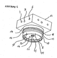
Diese Abbildung zeigt die detaillierte Funktions- / Anschlusseinheit (11). Diese Abbildung soll zum einem das Konzept der Aneinanderreihbarkeit mittels prismatischen Oberteil und der leichten Austauschbarkeit der Membranen mittels Schraubgewinde für das Modulrohr verdeutlichen. Nachfolgend weitere Details:
- Hier ist mit (12) das prismatische Oberteil und mit (16) das zylindrische Unterteil dargestellt. In diesem Fall ist das zylindrische Unterteil mit dem Anschlussgewinde (19) zur Aufnahme des Druckrohres (4) versehen. In die Aufnahmebohrung des Permeatsammelrohres (15) wird das Permeatsammelrohr der Membran (5) eingesteckt und dabei das Oberteil der Membran mit Dichtung (8) abgedichtet, wobei diese Dichtung auch an der Membran angebracht sein kann. Die komplette Funktion wird in
Abb. 5 beschrieben.
- Here, (12) shows the prismatic upper part and (16) the cylindrical lower part. In this case, the cylindrical lower part with the connecting thread (19) for receiving the pressure tube (4) is provided. Into the receiving bore of the permeate collection tube (15), the permeate collection tube of the membrane (5) is inserted while sealing the upper part of the membrane with seal (8), which seal may also be attached to the membrane. The complete function will be in
Fig. 5 described.
Die Flüssigkeitskanäle (50) und die Stege (51) dienen der gleichmäßigen Verteilung der Flüssigkeitszuführung in den Ringspalt zwischen Membran und Druckrohrinnenseite.The liquid channels (50) and the webs (51) serve to uniformly distribute the liquid feed into the annular gap between the membrane and the inside of the pressure pipe.
Der Membrananschlag (52) sorgt für einen ungehinderten Abfluss des Retentats in die Bohrung (14).The membrane stop (52) ensures an unhindered outflow of the retentate into the bore (14).
Das prismatische Oberteil kann zusätzlich Aufnahmeanschlüsse für mess- und regeltechnische Aufgaben beinhalten. Die Geometrie ist insbesondere für das Platz sparende Aneinanderreihen mehrerer Einheiten zweckmäßig.The prismatic upper part can additionally contain receiving connections for measuring and control tasks. The geometry is particularly useful for the space-saving juxtaposition of multiple units.
Der Filtratanschluss 7 ist in der Regel immer mittig angeordnet. Die Anschlüsse 3,6 sind vorteilhaft symmetrisch zu 7 und liegen auf einer gemeinsamen horizontalen Ebene zueinander. Damit ist es möglich, die Funktions-/Anschlusseinheit 11 bei einem Filtersystem jeweils um 180° zu drehen und so aneinander zu reihen, dass es zu keiner Richtungsänderung des Flusses innerhalb der Filtermodule kommt. Es kann aber auch konstruktiv zweckmäßig sein, von dieser Symmetrie abzuweichen, um Flussänderungen innerhalb des Filtermoduls zu erreichen.The
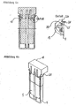
Diese Abbildung soll die Funktion hinsichtlich Totraumfreiheit und leichter Auswechselbarkeit der Membran verdeutlichen. Bevorzugt wird diese Konstruktion bei auswechselbaren Membranen mit Kunststoffdruckrohren.This figure is intended to clarify the function with regard to freedom from dead space and easier interchangeability of the membrane. This construction is preferred for interchangeable membranes with plastic pressure pipes.
Die Flüssigkeitszufuhr erfolgt an Anschluss (3). Die Flüssigkeit oder auch das Gas fließen über die Auslassbohrung mit umfließendem Ringspalt (13) außen an dem Aufnahmezylinder (17) der Membran in die Flüssigkeitskanäle (50) an der Außenseite des Zylinders gleichmäßig verteilt in den Ringspalt (21).The liquid is supplied to port (3). The liquid or else the gas flow via the outlet bore with annular gap (13) flowing around outside of the receiving cylinder (17) of the membrane into the liquid channels (50) on the outside of the cylinder evenly distributed in the annular gap (21).
Die Flüssigkeitszufuhr in die Membran erfolgt über die Stirnseite (22). Dabei wird das Filtrat zum Permeatsammelrohr (44) filtriert und verlässt über den Filtratanschluss (7) die Funktions- / Anschlusseinheit (11). Der Retentataustritt erfolgt stirnseitig an (45). Das Retentat verlässt über den Retentatanschluss (6) die Funktions- / Anschlusseinheit.The liquid supply to the membrane via the end face (22). The filtrate is filtered to the permeate collection tube (44) and leaves the functional / connection unit (11) via the filtrate connection (7). The retentate exit occurs at the front (45). The retentate leaves the function / connection unit via the retentate connection (6).
Damit der Flüssigkeitsaustritt (45) an der gesamten Stirnfläche erfolgen kann, hat der Aufnahmezylinder der Membran (17) an seiner Innenseite einen Anschlag (52), auf den sich die Membran am umfangseitigen Rand abstützt.Thus, the liquid outlet (45) can take place on the entire end face, the receiving cylinder of the membrane (17) on its inside a stop (52) on which the membrane is supported on the peripheral edge.
Die besondere Ausgestaltung sieht ein aufgeschraubtes Druckrohr (4) vor, welches mittels Innengewinde (23) an der Funktions- / Anschlusseinheit befestigt wird.The special embodiment provides a screwed on pressure tube (4), which is fastened by means of internal thread (23) on the function / connection unit.
Die Abdichtung des Modulrohres erfolgt mittels Dichtelement (18).The sealing of the module tube by means of sealing element (18).
Als kraftschlüssige Verstärkung der Schraubverbindung kann eine Rohrhülse über die Außenseite des Modulrohres (nicht abgebildet) im Gewindebereich gepresst werden.As non-positive reinforcement of the screw connection, a tube sleeve can be pressed over the outside of the module tube (not shown) in the threaded area.
Diese Abbildung soll die Funktion hinsichtlich Totraumfreiheit und leichter Auswechselbarkeit der Membran bei Einsatz von metallischen Druckrohren verdeutlichen.This figure is intended to clarify the function in terms of dead space and easier interchangeability of the membrane when using metallic pressure pipes.
Bei sehr dünnwandigen z.B. metallischen Druckrohren ist eine Gewindebefestigung wie in
Dabei liegt die Oberseite der Flanschklammer (24) in einer Haltenut (26) der Funktions- / Anschlusseinheit (11).In this case, the upper side of the flange clamp (24) lies in a retaining groove (26) of the functional / connection unit (11).
Die Flanschklammer (24) kann dabei aus 2 Halbkreisen oder mehreren Kreissegmenten bestehen. Sie kann jedoch auch aus einer Klammer mit einseitiger Verschraubung bestehen. Die auf der Funktions- / Anschlusseinheit in der Haltenut (26) liegende Seite hat dabei eine größere Auflagefläche als die Fläche am Bördelrand, da die Funktions- / Anschlusseinheit (11) in der Regel aus Kunststoff besteht und daher nicht die gleiche Festigkeit aufweist wie das metallische Druckrohr.The flange clamp (24) can consist of 2 semicircles or more circular segments. However, it can also consist of a clamp with one-sided screw. The lying on the function / connection unit in the retaining groove (26) side has a larger contact surface than the surface at the bead, since the function / connection unit (11) usually off Plastic and therefore does not have the same strength as the metallic pressure tube.
Zur Verbilligung der Flanschklammer besteht die Möglichkeit diese aus einem U-förmigen Blechmaterial kreisförmig zu biegen. In diesem Fall entfällt die Haltenut 26.To cheapen the flange clamp, it is possible to bend it from a U-shaped sheet metal material in a circle. In this case, the retaining
Bei hohen Drücken neigt der Flansch 25 zum Aufbiegen, deshalb kann der in einem Winkel zum Modulrohr nach außen gebördelte Flansch eine zusätzliche winklige Aufbördelung fluchtend zum Modulrohr erhalten. Diese von der Modulrohrwandung her gesehene Z-Form versteift den Flansch. In diesem Fall kann die Verbindung zwischen Modulrohr 4 und Funktions-Anschlusseinheit 11 mittels einer Flanschplatte mit Kreisausschnitt und Verbindungsschrauben hergestellt werden.At high pressures, the
Flüssigkeitszuführung und Membranaufnahme wurden bereits in
Diese Abbildung soll die Funktion bei Einsatz eines Einmaldruckrohres mit integrierter Membran als Billigvariante verdeutlichen.This figure is intended to illustrate the function when using a disposable pressure tube with integrated membrane as a low-cost variant.
In diesem Fall ist das prismatische Oberteil (27) vom zylindrischen Unterteil (28) mittels Schraubverbindung (30) voneinander lösbar. Dabei ist das Modulrohr (4) mit Schweißnaht (29) unlösbar am Unterteil (28) befestigt.In this case, the prismatic upper part (27) of the cylindrical lower part (28) by means of screw (30) from each other detachable. In this case, the module tube (4) with weld (29) is permanently attached to the lower part (28).
Die Flüssigkeitszufuhr erfolgt wie in
Zur Verbesserung des Retentatabflusses (6) und zur Erhöhung der Strömungsquerschnitte im Retentat-Abflusskanal (34) kann ein zusätzlicher Retentat- Abflusskanal (36) im Oberteil (27) hinzugefügt bzw. als alleiniger Abflusskanal genutzt werden.To improve the retentate effluent (6) and to increase the flow cross sections in the retentate effluent channel (34), an additional retentate effluent channel (36) can be added in the upper part (27) or used as the sole effluent channel.
Zur Verbesserung der Flüssigkeitsverteilung und zur Erhöhung der Strömungsquerschnitte der zuführenden Flüssigkeit kann zu dem Strömungskanal (35) ein zusätzlicher Strömungskanal (37) im Oberteil (27) hinzugefügt bzw. als alleiniger Strömungskanal genutzt werden.To improve the liquid distribution and to increase the flow cross sections of the feeding liquid, an additional flow channel (37) in the upper part (27) can be added to the flow channel (35) or used as the sole flow channel.
Die Abdichtung zu den einzelnen Flüssigkeitskanälen erfolgt mit Dichtelementen (31 / 32 / 33). Abhängig von der Anzahl der Abfluss- bzw. Zuflusskanäle ist das Oberteil (27) dreistufig (54 / 55 / 56) oder fünfstufig (54 / 55 / 56 / 57 / 58) ausgebildet.The seal to the individual liquid channels is made with sealing elements (31/32/33). Depending on the number of outflow or inflow channels, the upper part (27) is designed in three stages (54/55/56) or five stages (54/55/56/57/58).
Veranschaulicht in perspektivischer Weise die schematischen Darstellungen von 7.Illustrates in perspective the schematic illustrations of FIG. 7.
Diese Abbildung zeigt die einfache Möglichkeit des Ausbaues zu einem Filtersystem paralleler Ausführung mit standardisierten Komponenten und geringen Fertigungsaufwand.This figure shows the simple possibility of removal to a filter system of parallel design with standardized components and low production costs.
Ausgehend von
Bei paralleler Ausführung werden die Strömungskanäle 3,6,7 mittels Stecknippel 42 wie dargestellt miteinander verbunden. Bedingt durch unterschiedliche Anforderung an die Permeatqualität, den Wirkungsgrad des Gesamtsystems oder auch der Qualität der zufließenden Flüssigkeit ist auch eine Seriellschaltung- bzw. die Kombination aus Parallel- und Seriellschaltung der Filterelemente in Betracht zu ziehen, wie aus
Dabei erhalten die Funktions-/Anschlusseinheiten an einer oder mehreren - für die Zusammenschaltung konstruktiv günstigen Seite die Anschlüsse 3,6,7.The function / connection units receive the
Es wird betont, dass die Erfindung nicht auf die beschriebenen und dargestellten Ausführungsformen beschränkt ist. Vielmehr sind alle offenbarten Merkmale auf jede Weise einzeln miteinander kombinierbar.
Claims (14)
- A filter module with a pressure pipe and membrane disposed therein, connections for a liquid to be supplied, preferably raw water, and for discharging filtrate and retentate, a functional/connection unit (11), which is connected to one end of the pressure pipe (4), and has an upper portion (12) and a lower portion, wherein all the connections (3, 6, 7) are provided on the upper portion (12) and flow passages communicating with the connections (3, 6, 7) pass through the lower portion, wherein provided between the pressure pipe (4) and the membrane (5) there is an open annular space (21), through which the supplied fluid flows to the underside of the membrane (5), and wherein the pressure pipe (4) has a closed base, characterised in that the upper portion (12) has the shape of a prism and that all three connections (3, 6, 7) are provided in each of a plurality of side surfaces of the prism so that two or more functional/connection units (11) are connectable together to form a filter system, wherein its side surfaces extend parallel to one another, wherein connections that are not required are closable by means of unbored plugs.
- A filter module as claimed in claim 1, characterised in that the functional/connection unit (11) is connected to the upper end of the pressure pipe (4).
- A filter module as claimed in claim 1, characterised in that the functional/connection unit (11) is connected to the lower end of the pressure pipe (4).
- A filter module a claimed in one of claims 1 to 3, characterised in that adjacent functional/connection units (11) are connectable by means of plug connectors (42).
- A filter module as claimed in claim 4, characterised in that the plug connectors (42) are lockable.
- A filter module as claimed in one of claims 1 to 5, characterised in that the lower portion has a cylindrical shape and a connector for the pressure pipe (4) and a connector (52) for the membrane (5) such that the supplied fluid is introduced between the membrane (5) and the inner wall of the pressure pipe (4).
- A filter module as claimed in one of claims 1 to 6, characterised in that the functional/connection unit (11) further has supply and drain connections, which serve to connect the system to external devices, for sample removal or the injection of media, which are disposed on the side surfaces or the end surface of the upper portion (12).
- A filter module as claimed in one of claims 1 to 7, characterised in that the functional/connection unit (11) has additional receiving connections for measuring and control devices, such as sensors for measuring condition parameters, throughputs and material properties and/or devices for influencing the gas/liquid flows in the sense of releasing, accelerating, blocking, throttling or switching.
- A filter module as claimed in one of claims 1 to 8, characterised in that the pressure pipe (4) has a flange (25) and is connected by means of clips (24) to the lower portion of the functional/connection unit (11).
- A filter module as claimed in one of claims 1 to 8, characterised in that the pressure pipe (4) has a screw thread (23) and is connected by means of a screw connection to the lower portion of the functional/connection unit (11).
- A filter module as claimed in one of claims 1 to 10, characterised in that the upper portion (27) and lower portion (28) of the functional/connection unit (11) are releasably connected together by means of a screw connection.
- A filter module as claimed in claim 11, characterised in that the pressure pipe (4) and the membrane (5) are unreleasably connected to the lower portion (28) to be screwed in.
- A filter module as claimed in claim 11, characterised in that the upper portion of the functional/connection unit 11, has a central three-stepped bore for receiving the lower portion to be screwed in.
- A filter module as claimed in one of claims 1 to 13, characterised in that the base, which is opposite to the functional/connection unit (11), of the pressure pipe (4) is openable.
Priority Applications (2)
| Application Number | Priority Date | Filing Date | Title |
|---|---|---|---|
| EP11000605.3A EP2319611B1 (en) | 2007-09-20 | 2008-07-24 | Filtration module with manifold |
| PL08801110T PL2190561T3 (en) | 2007-09-20 | 2008-07-24 | Filter module and the stringing thereof to form a filter system |
Applications Claiming Priority (2)
| Application Number | Priority Date | Filing Date | Title |
|---|---|---|---|
| DE102007044922A DE102007044922B4 (en) | 2007-09-20 | 2007-09-20 | Filter module and its juxtaposition to a filter system |
| PCT/DE2008/001272 WO2009036717A2 (en) | 2007-09-20 | 2008-07-24 | Filter module and the stringing thereof to form a filter system |
Related Child Applications (1)
| Application Number | Title | Priority Date | Filing Date |
|---|---|---|---|
| EP11000605.3A Division EP2319611B1 (en) | 2007-09-20 | 2008-07-24 | Filtration module with manifold |
Publications (2)
| Publication Number | Publication Date |
|---|---|
| EP2190561A2 EP2190561A2 (en) | 2010-06-02 |
| EP2190561B1 true EP2190561B1 (en) | 2011-02-09 |
Family
ID=40120108
Family Applications (2)
| Application Number | Title | Priority Date | Filing Date |
|---|---|---|---|
| EP08801110A Not-in-force EP2190561B1 (en) | 2007-09-20 | 2008-07-24 | Filter module and the stringing thereof to form a filter system |
| EP11000605.3A Active EP2319611B1 (en) | 2007-09-20 | 2008-07-24 | Filtration module with manifold |
Family Applications After (1)
| Application Number | Title | Priority Date | Filing Date |
|---|---|---|---|
| EP11000605.3A Active EP2319611B1 (en) | 2007-09-20 | 2008-07-24 | Filtration module with manifold |
Country Status (12)
| Country | Link |
|---|---|
| US (1) | US9162187B2 (en) |
| EP (2) | EP2190561B1 (en) |
| CN (1) | CN101855006B (en) |
| AT (1) | ATE497832T1 (en) |
| BR (1) | BRPI0815969B1 (en) |
| DE (2) | DE102007044922B4 (en) |
| ES (2) | ES2533430T3 (en) |
| MX (1) | MX2010003127A (en) |
| PL (1) | PL2190561T3 (en) |
| PT (1) | PT2190561E (en) |
| RU (1) | RU2455053C2 (en) |
| WO (1) | WO2009036717A2 (en) |
Families Citing this family (19)
| Publication number | Priority date | Publication date | Assignee | Title |
|---|---|---|---|---|
| US20110120928A1 (en) * | 2009-11-25 | 2011-05-26 | Watts Water Technologies, Inc. | Easy change filter assembly for reverse osmosis membrane water purification system |
| DE102010009816B4 (en) * | 2010-03-02 | 2016-11-24 | Manfred Völker | Fluid system for supplying a device with highly pure liquid |
| ITME20110001A1 (en) * | 2011-01-28 | 2012-07-29 | Terminter Srl | NEW OSMOSIS SYSTEM |
| NL2006101C2 (en) * | 2011-01-31 | 2012-08-01 | Artemis Systems B V | DEVICE FOR PURIFYING RAW WATER. |
| DE102011006543A1 (en) * | 2011-03-31 | 2012-10-04 | Krones Aktiengesellschaft | Membranfitrationsmodul |
| DE102011109093A1 (en) * | 2011-08-01 | 2013-02-07 | Manfred Völker | Combination of a single-user RO device with a hemodialysis machine |
| DE102012006320A1 (en) * | 2012-03-28 | 2013-10-02 | Manfred Völker | Membrane for reverse osmosis |
| DE102012213483A1 (en) * | 2012-07-31 | 2014-02-06 | Krones Ag | Membrane element, membrane module and membrane compound |
| US20140069856A1 (en) * | 2012-09-13 | 2014-03-13 | Ying-Chen Lin | Water gathering cover |
| EP2907565A1 (en) * | 2014-02-17 | 2015-08-19 | Bayer Technology Services GmbH | Dialysis unit for continuous buffer or media exchange from a protein solution |
| WO2016074630A1 (en) * | 2014-11-14 | 2016-05-19 | 天纳克(苏州)排放系统有限公司 | Filter assembly |
| EP3053640B1 (en) | 2015-02-05 | 2018-12-19 | Holger Knappe | Modular distribution head for membrane housing body |
| CN107096386A (en) * | 2016-02-19 | 2017-08-29 | 上海奥星制药技术装备有限公司 | Reverse osmosis membrane housing |
| ES2908063T3 (en) * | 2017-01-13 | 2022-04-27 | Bwt Aqua Ag | Device and procedure for the treatment of saline water by means of reverse osmosis |
| EP3473329A1 (en) * | 2017-10-19 | 2019-04-24 | 3M Innovative Properties Company | Integrated membrane module rack |
| EP4142910A4 (en) | 2020-04-28 | 2024-04-24 | Entegris Inc | Modular filter manifold |
| WO2022106432A1 (en) | 2020-11-18 | 2022-05-27 | Zhejiang Qinyuan Water Treatment S. T. Co., Ltd. | A membrane filter unit |
| USD981531S1 (en) * | 2021-03-24 | 2023-03-21 | LANG Beverages SA | Water filter |
| CN113368565B (en) * | 2021-06-30 | 2022-07-19 | 吉林信达石油技术服务有限公司 | Petroleum fracturing fluid wastewater pretreatment device |
Family Cites Families (27)
| Publication number | Priority date | Publication date | Assignee | Title |
|---|---|---|---|---|
| US4476015A (en) * | 1982-11-02 | 1984-10-09 | V. J. Ciccone & Associates, Inc. | Multiple element fluid separation device |
| JPS63163002A (en) * | 1986-12-26 | 1988-07-06 | Kuroda Precision Ind Ltd | Connection unit of fluid control element |
| DE3943631C2 (en) * | 1989-05-20 | 1992-10-29 | Seitz-Filter-Werke Theo & Geo Seitz Gmbh Und Co, 6550 Bad Kreuznach, De | Cross-flow liq. filtration by hollow membranes |
| US5194149A (en) * | 1989-09-29 | 1993-03-16 | Memtec Limited | Filter cartridge manifold |
| US5221473A (en) * | 1989-10-13 | 1993-06-22 | Burrows Bruce D | Filter cartridge assembly for a reverse osmosis purification system |
| US5354464A (en) * | 1990-03-14 | 1994-10-11 | Water Factory Systems | Multi-port connecting device |
| US5128035A (en) * | 1990-03-15 | 1992-07-07 | Clack Corporation | Fluid flow control device for water treatment systems |
| WO1991016124A1 (en) * | 1990-04-20 | 1991-10-31 | Memtec Limited | Modular microporous filter assemblies |
| US5389260A (en) * | 1993-04-02 | 1995-02-14 | Clack Corporation | Brine seal for tubular filter |
| DE9422466U1 (en) * | 1993-07-09 | 2003-01-30 | Parker Hannifin Corp | Separable connector for pressure fluid components such as filters, regulators, manifolds, etc. - has joining block forming slide fit seal between pair of components using slide rails and tracks to secure two parts and O= ring to make fluid tight seal for fluid port |
| US5401399A (en) * | 1993-08-27 | 1995-03-28 | Magnusson; Jan H. | Water purification system |
| US5865996A (en) * | 1996-08-14 | 1999-02-02 | Reid; Roger P. | Water purifier with collet and tube support |
| JP2001149933A (en) * | 1999-11-29 | 2001-06-05 | Nitto Denko Corp | Reverse-osmosis membrane-type cartridge polisher |
| US6436282B1 (en) * | 2000-08-08 | 2002-08-20 | Plymouth Products, Inc. | Flow control module for RO water treatment system |
| DE50002390D1 (en) * | 2000-12-22 | 2003-07-03 | Gruenbeck Josef Wasseraufb | Device for processing a liquid |
| RU23140U1 (en) * | 2001-03-01 | 2002-05-27 | Ставропольская Государственная Сельскохозяйственная Академия | MEMBRANE MACHINE |
| US7604738B2 (en) * | 2002-02-08 | 2009-10-20 | Schroeder Industries Llc | Connecting end cap for a filter |
| US6740235B2 (en) * | 2002-03-04 | 2004-05-25 | Culligan International Company | Swivelling filter head assembly |
| FR2840451B1 (en) * | 2002-06-04 | 2004-08-13 | Centre Nat Rech Scient | DEVICE FOR PRODUCING A PLASMA TABLECLOTH |
| AU2003245485A1 (en) * | 2002-06-12 | 2003-12-31 | The Water System Group, Inc. | Purified water supply system |
| FR2845082B1 (en) * | 2002-09-26 | 2006-02-10 | Millipore Corp | MODULE FOR PURIFYING A FLUID, IN PARTICULAR WATER |
| US7017611B2 (en) * | 2003-02-04 | 2006-03-28 | Watts Regulator C. | One-piece manifold for a reverse osmosis system |
| JP2006525120A (en) * | 2003-05-02 | 2006-11-09 | キュノ、インコーポレーテッド | Crossflow filtration device with fast dry exchange element |
| US7294262B2 (en) * | 2003-08-27 | 2007-11-13 | Sta-Rite Industries, Llc | Modular fluid treatment apparatus |
| CA2771265C (en) * | 2005-01-27 | 2014-05-06 | Ecowater Systems, Llc | Encapsulated water treatment system |
| KR100712266B1 (en) * | 2005-03-24 | 2007-05-17 | 주식회사 피코그램 | purification filter of using connector and water purification ddevice |
| DE102005052486A1 (en) * | 2005-11-03 | 2007-05-10 | Asana Ro-Wasserbehandlung Gmbh | Water filter housing cap closure has connection holes with smooth sidewalls for matching push-fit connectors |
-
2007
- 2007-09-20 DE DE102007044922A patent/DE102007044922B4/en active Active
-
2008
- 2008-07-24 PL PL08801110T patent/PL2190561T3/en unknown
- 2008-07-24 US US12/679,094 patent/US9162187B2/en active Active
- 2008-07-24 WO PCT/DE2008/001272 patent/WO2009036717A2/en active Application Filing
- 2008-07-24 RU RU2010115478/05A patent/RU2455053C2/en active
- 2008-07-24 MX MX2010003127A patent/MX2010003127A/en active IP Right Grant
- 2008-07-24 AT AT08801110T patent/ATE497832T1/en active
- 2008-07-24 PT PT08801110T patent/PT2190561E/en unknown
- 2008-07-24 ES ES11000605.3T patent/ES2533430T3/en active Active
- 2008-07-24 EP EP08801110A patent/EP2190561B1/en not_active Not-in-force
- 2008-07-24 BR BRPI0815969A patent/BRPI0815969B1/en active IP Right Grant
- 2008-07-24 CN CN200880115639.7A patent/CN101855006B/en active Active
- 2008-07-24 DE DE502008002576T patent/DE502008002576D1/en active Active
- 2008-07-24 ES ES08801110T patent/ES2360163T3/en active Active
- 2008-07-24 EP EP11000605.3A patent/EP2319611B1/en active Active
Also Published As
| Publication number | Publication date |
|---|---|
| BRPI0815969B1 (en) | 2020-02-04 |
| DE102007044922B4 (en) | 2012-04-19 |
| PT2190561E (en) | 2011-05-12 |
| RU2010115478A (en) | 2011-10-27 |
| US20100307965A1 (en) | 2010-12-09 |
| DE102007044922A1 (en) | 2009-04-09 |
| EP2190561A2 (en) | 2010-06-02 |
| RU2455053C2 (en) | 2012-07-10 |
| ES2533430T3 (en) | 2015-04-10 |
| WO2009036717A2 (en) | 2009-03-26 |
| DE502008002576D1 (en) | 2011-03-24 |
| EP2319611B1 (en) | 2015-01-07 |
| US9162187B2 (en) | 2015-10-20 |
| WO2009036717A3 (en) | 2009-06-18 |
| ES2360163T3 (en) | 2011-06-01 |
| BRPI0815969A2 (en) | 2018-02-14 |
| CN101855006B (en) | 2015-12-16 |
| PL2190561T3 (en) | 2011-07-29 |
| ATE497832T1 (en) | 2011-02-15 |
| CN101855006A (en) | 2010-10-06 |
| EP2319611A1 (en) | 2011-05-11 |
| MX2010003127A (en) | 2010-09-09 |
Similar Documents
| Publication | Publication Date | Title |
|---|---|---|
| EP2190561B1 (en) | Filter module and the stringing thereof to form a filter system | |
| EP1251944B1 (en) | Device and assembly for cross-flow filtration | |
| DE3916511A1 (en) | MEMBRANE FILTER DEVICE FOR MICRO AND ULTRAFILTRATION OF FLUIDS IN THE CROSSFLOW PROCESS | |
| DE3317517C2 (en) | Device for filtering and separating liquid and gaseous media | |
| DE602005002206T2 (en) | Connection adapter for a tangential filtration cassette | |
| DE102006022502A1 (en) | Filter unit for wastewater treatment and drinking water production | |
| EP1812147A1 (en) | Device for filtering solids from liquids | |
| DE602004013309T2 (en) | APPARATUS FOR SEPARATING A FLUID IN AT LEAST TWO FRACTIONS BY MEANS OF A VARIETY OF MEMBRANES AND ITS USE | |
| US20100140153A1 (en) | Manifold block for reverse osmosis systems | |
| EP1842580B1 (en) | Device and continuous electrochemical desalination with an integrated membrane stage | |
| EP3241806B1 (en) | Terminal filter device for reduction of microbiological contaminants in an aqueous medium | |
| EP1747811B1 (en) | Filter for the production of substantially germ-free water | |
| DE2945317A1 (en) | DEVICE FOR WATER DESALINATION AND PURIFICATION BY REVERSE OSMOSIS AND ULTRAFILTRATION | |
| DE102019132699A1 (en) | Device for filtering components from a fluid | |
| DE19933223B4 (en) | Process for the thermal disinfection of hemodialysis machines | |
| DE102009031044A1 (en) | Connection for supply water main pipe to consumer between reverse osmosis system and dialysis equipment, comprises housing and filling line for supply water, where filling line is closed by permeated opening valve | |
| EP2505257B1 (en) | Membrane filtration module | |
| EP3053640B1 (en) | Modular distribution head for membrane housing body | |
| DE3943631C2 (en) | Cross-flow liq. filtration by hollow membranes | |
| WO2019242916A1 (en) | Filter system for biopharmaceutical processes | |
| DE202022001680U1 (en) | Filter device provided for micro and/or ultra filtration and/or for solid-liquid separation | |
| DE3341642A1 (en) | Filter arrangement comprising a casing and at least one filter element | |
| DD280261A1 (en) | COMPOUND REACTOR FOR ION EXCHANGE PROCESSES FOR OBTAINING PARTICLE-FREE DEIONIZED WATER |
Legal Events
| Date | Code | Title | Description |
|---|---|---|---|
| PUAI | Public reference made under article 153(3) epc to a published international application that has entered the european phase |
Free format text: ORIGINAL CODE: 0009012 |
|
| 17P | Request for examination filed |
Effective date: 20100327 |
|
| AK | Designated contracting states |
Kind code of ref document: A2 Designated state(s): AT BE BG CH CY CZ DE DK EE ES FI FR GB GR HR HU IE IS IT LI LT LU LV MC MT NL NO PL PT RO SE SI SK TR |
|
| AX | Request for extension of the european patent |
Extension state: AL BA MK RS |
|
| GRAP | Despatch of communication of intention to grant a patent |
Free format text: ORIGINAL CODE: EPIDOSNIGR1 |
|
| GRAS | Grant fee paid |
Free format text: ORIGINAL CODE: EPIDOSNIGR3 |
|
| GRAA | (expected) grant |
Free format text: ORIGINAL CODE: 0009210 |
|
| AK | Designated contracting states |
Kind code of ref document: B1 Designated state(s): AT BE BG CH CY CZ DE DK EE ES FI FR GB GR HR HU IE IS IT LI LT LU LV MC MT NL NO PL PT RO SE SI SK TR |
|
| REG | Reference to a national code |
Ref country code: GB Ref legal event code: FG4D Free format text: NOT ENGLISH |
|
| REG | Reference to a national code |
Ref country code: CH Ref legal event code: EP |
|
| REG | Reference to a national code |
Ref country code: IE Ref legal event code: FG4D Free format text: LANGUAGE OF EP DOCUMENT: GERMAN |
|
| REF | Corresponds to: |
Ref document number: 502008002576 Country of ref document: DE Date of ref document: 20110324 Kind code of ref document: P |
|
| REG | Reference to a national code |
Ref country code: DE Ref legal event code: R096 Ref document number: 502008002576 Country of ref document: DE Effective date: 20110324 |
|
| REG | Reference to a national code |
Ref country code: CH Ref legal event code: NV Representative=s name: KIRKER & CIE S.A. |
|
| REG | Reference to a national code |
Ref country code: PT Ref legal event code: SC4A Free format text: AVAILABILITY OF NATIONAL TRANSLATION Effective date: 20110505 |
|
| REG | Reference to a national code |
Ref country code: NL Ref legal event code: VDEP Effective date: 20110209 Ref country code: ES Ref legal event code: FG2A Ref document number: 2360163 Country of ref document: ES Kind code of ref document: T3 Effective date: 20110601 |
|
| LTIE | Lt: invalidation of european patent or patent extension |
Effective date: 20110209 |
|
| PG25 | Lapsed in a contracting state [announced via postgrant information from national office to epo] |
Ref country code: HR Free format text: LAPSE BECAUSE OF FAILURE TO SUBMIT A TRANSLATION OF THE DESCRIPTION OR TO PAY THE FEE WITHIN THE PRESCRIBED TIME-LIMIT Effective date: 20110209 Ref country code: LV Free format text: LAPSE BECAUSE OF FAILURE TO SUBMIT A TRANSLATION OF THE DESCRIPTION OR TO PAY THE FEE WITHIN THE PRESCRIBED TIME-LIMIT Effective date: 20110209 Ref country code: GR Free format text: LAPSE BECAUSE OF FAILURE TO SUBMIT A TRANSLATION OF THE DESCRIPTION OR TO PAY THE FEE WITHIN THE PRESCRIBED TIME-LIMIT Effective date: 20110510 Ref country code: NO Free format text: LAPSE BECAUSE OF FAILURE TO SUBMIT A TRANSLATION OF THE DESCRIPTION OR TO PAY THE FEE WITHIN THE PRESCRIBED TIME-LIMIT Effective date: 20110509 Ref country code: LT Free format text: LAPSE BECAUSE OF FAILURE TO SUBMIT A TRANSLATION OF THE DESCRIPTION OR TO PAY THE FEE WITHIN THE PRESCRIBED TIME-LIMIT Effective date: 20110209 Ref country code: SE Free format text: LAPSE BECAUSE OF FAILURE TO SUBMIT A TRANSLATION OF THE DESCRIPTION OR TO PAY THE FEE WITHIN THE PRESCRIBED TIME-LIMIT Effective date: 20110209 |
|
| REG | Reference to a national code |
Ref country code: PL Ref legal event code: T3 |
|
| PG25 | Lapsed in a contracting state [announced via postgrant information from national office to epo] |
Ref country code: FI Free format text: LAPSE BECAUSE OF FAILURE TO SUBMIT A TRANSLATION OF THE DESCRIPTION OR TO PAY THE FEE WITHIN THE PRESCRIBED TIME-LIMIT Effective date: 20110209 Ref country code: NL Free format text: LAPSE BECAUSE OF FAILURE TO SUBMIT A TRANSLATION OF THE DESCRIPTION OR TO PAY THE FEE WITHIN THE PRESCRIBED TIME-LIMIT Effective date: 20110209 Ref country code: CY Free format text: LAPSE BECAUSE OF FAILURE TO SUBMIT A TRANSLATION OF THE DESCRIPTION OR TO PAY THE FEE WITHIN THE PRESCRIBED TIME-LIMIT Effective date: 20110209 Ref country code: BG Free format text: LAPSE BECAUSE OF FAILURE TO SUBMIT A TRANSLATION OF THE DESCRIPTION OR TO PAY THE FEE WITHIN THE PRESCRIBED TIME-LIMIT Effective date: 20110509 |
|
| REG | Reference to a national code |
Ref country code: IE Ref legal event code: FD4D |
|
| REG | Reference to a national code |
Ref country code: HU Ref legal event code: AG4A Ref document number: E011021 Country of ref document: HU |
|
| PG25 | Lapsed in a contracting state [announced via postgrant information from national office to epo] |
Ref country code: EE Free format text: LAPSE BECAUSE OF FAILURE TO SUBMIT A TRANSLATION OF THE DESCRIPTION OR TO PAY THE FEE WITHIN THE PRESCRIBED TIME-LIMIT Effective date: 20110209 Ref country code: DK Free format text: LAPSE BECAUSE OF FAILURE TO SUBMIT A TRANSLATION OF THE DESCRIPTION OR TO PAY THE FEE WITHIN THE PRESCRIBED TIME-LIMIT Effective date: 20110209 Ref country code: IE Free format text: LAPSE BECAUSE OF FAILURE TO SUBMIT A TRANSLATION OF THE DESCRIPTION OR TO PAY THE FEE WITHIN THE PRESCRIBED TIME-LIMIT Effective date: 20110209 |
|
| PG25 | Lapsed in a contracting state [announced via postgrant information from national office to epo] |
Ref country code: SK Free format text: LAPSE BECAUSE OF FAILURE TO SUBMIT A TRANSLATION OF THE DESCRIPTION OR TO PAY THE FEE WITHIN THE PRESCRIBED TIME-LIMIT Effective date: 20110209 Ref country code: RO Free format text: LAPSE BECAUSE OF FAILURE TO SUBMIT A TRANSLATION OF THE DESCRIPTION OR TO PAY THE FEE WITHIN THE PRESCRIBED TIME-LIMIT Effective date: 20110209 |
|
| PGFP | Annual fee paid to national office [announced via postgrant information from national office to epo] |
Ref country code: CZ Payment date: 20110718 Year of fee payment: 4 |
|
| PLBE | No opposition filed within time limit |
Free format text: ORIGINAL CODE: 0009261 |
|
| STAA | Information on the status of an ep patent application or granted ep patent |
Free format text: STATUS: NO OPPOSITION FILED WITHIN TIME LIMIT |
|
| PG25 | Lapsed in a contracting state [announced via postgrant information from national office to epo] |
Ref country code: MT Free format text: LAPSE BECAUSE OF FAILURE TO SUBMIT A TRANSLATION OF THE DESCRIPTION OR TO PAY THE FEE WITHIN THE PRESCRIBED TIME-LIMIT Effective date: 20110209 |
|
| 26N | No opposition filed |
Effective date: 20111110 |
|
| BERE | Be: lapsed |
Owner name: VOLKER, MANFRED Effective date: 20110731 |
|
| PG25 | Lapsed in a contracting state [announced via postgrant information from national office to epo] |
Ref country code: MC Free format text: LAPSE BECAUSE OF NON-PAYMENT OF DUE FEES Effective date: 20110731 |
|
| REG | Reference to a national code |
Ref country code: DE Ref legal event code: R097 Ref document number: 502008002576 Country of ref document: DE Effective date: 20111110 |
|
| PG25 | Lapsed in a contracting state [announced via postgrant information from national office to epo] |
Ref country code: BE Free format text: LAPSE BECAUSE OF NON-PAYMENT OF DUE FEES Effective date: 20110731 |
|
| REG | Reference to a national code |
Ref country code: PT Ref legal event code: MM4A Free format text: LAPSE DUE TO NON-PAYMENT OF FEES Effective date: 20120424 |
|
| PG25 | Lapsed in a contracting state [announced via postgrant information from national office to epo] |
Ref country code: SI Free format text: LAPSE BECAUSE OF FAILURE TO SUBMIT A TRANSLATION OF THE DESCRIPTION OR TO PAY THE FEE WITHIN THE PRESCRIBED TIME-LIMIT Effective date: 20110209 |
|
| PG25 | Lapsed in a contracting state [announced via postgrant information from national office to epo] |
Ref country code: PT Free format text: LAPSE BECAUSE OF NON-PAYMENT OF DUE FEES Effective date: 20120424 |
|
| PGFP | Annual fee paid to national office [announced via postgrant information from national office to epo] |
Ref country code: HU Payment date: 20120808 Year of fee payment: 5 |
|
| GBPC | Gb: european patent ceased through non-payment of renewal fee |
Effective date: 20120724 |
|
| PG25 | Lapsed in a contracting state [announced via postgrant information from national office to epo] |
Ref country code: GB Free format text: LAPSE BECAUSE OF NON-PAYMENT OF DUE FEES Effective date: 20120724 |
|
| PG25 | Lapsed in a contracting state [announced via postgrant information from national office to epo] |
Ref country code: LU Free format text: LAPSE BECAUSE OF NON-PAYMENT OF DUE FEES Effective date: 20110724 |
|
| PG25 | Lapsed in a contracting state [announced via postgrant information from national office to epo] |
Ref country code: IS Free format text: LAPSE BECAUSE OF FAILURE TO SUBMIT A TRANSLATION OF THE DESCRIPTION OR TO PAY THE FEE WITHIN THE PRESCRIBED TIME-LIMIT Effective date: 20110209 |
|
| PG25 | Lapsed in a contracting state [announced via postgrant information from national office to epo] |
Ref country code: TR Free format text: LAPSE BECAUSE OF FAILURE TO SUBMIT A TRANSLATION OF THE DESCRIPTION OR TO PAY THE FEE WITHIN THE PRESCRIBED TIME-LIMIT Effective date: 20110209 |
|
| PG25 | Lapsed in a contracting state [announced via postgrant information from national office to epo] |
Ref country code: CZ Free format text: LAPSE BECAUSE OF NON-PAYMENT OF DUE FEES Effective date: 20130724 Ref country code: HU Free format text: LAPSE BECAUSE OF NON-PAYMENT OF DUE FEES Effective date: 20130725 |
|
| PGFP | Annual fee paid to national office [announced via postgrant information from national office to epo] |
Ref country code: ES Payment date: 20140627 Year of fee payment: 7 |
|
| REG | Reference to a national code |
Ref country code: AT Ref legal event code: MM01 Ref document number: 497832 Country of ref document: AT Kind code of ref document: T Effective date: 20130724 |
|
| PGFP | Annual fee paid to national office [announced via postgrant information from national office to epo] |
Ref country code: CH Payment date: 20140729 Year of fee payment: 7 Ref country code: DE Payment date: 20140911 Year of fee payment: 7 |
|
| PG25 | Lapsed in a contracting state [announced via postgrant information from national office to epo] |
Ref country code: AT Free format text: LAPSE BECAUSE OF NON-PAYMENT OF DUE FEES Effective date: 20130724 |
|
| PGFP | Annual fee paid to national office [announced via postgrant information from national office to epo] |
Ref country code: PL Payment date: 20140714 Year of fee payment: 7 Ref country code: FR Payment date: 20140623 Year of fee payment: 7 |
|
| PGFP | Annual fee paid to national office [announced via postgrant information from national office to epo] |
Ref country code: IT Payment date: 20140730 Year of fee payment: 7 |
|
| REG | Reference to a national code |
Ref country code: DE Ref legal event code: R119 Ref document number: 502008002576 Country of ref document: DE |
|
| REG | Reference to a national code |
Ref country code: CH Ref legal event code: PL |
|
| PG25 | Lapsed in a contracting state [announced via postgrant information from national office to epo] |
Ref country code: LI Free format text: LAPSE BECAUSE OF NON-PAYMENT OF DUE FEES Effective date: 20150731 Ref country code: DE Free format text: LAPSE BECAUSE OF NON-PAYMENT OF DUE FEES Effective date: 20160202 Ref country code: CH Free format text: LAPSE BECAUSE OF NON-PAYMENT OF DUE FEES Effective date: 20150731 Ref country code: IT Free format text: LAPSE BECAUSE OF NON-PAYMENT OF DUE FEES Effective date: 20150724 |
|
| REG | Reference to a national code |
Ref country code: FR Ref legal event code: ST Effective date: 20160331 |
|
| PG25 | Lapsed in a contracting state [announced via postgrant information from national office to epo] |
Ref country code: FR Free format text: LAPSE BECAUSE OF NON-PAYMENT OF DUE FEES Effective date: 20150731 |
|
| PG25 | Lapsed in a contracting state [announced via postgrant information from national office to epo] |
Ref country code: ES Free format text: LAPSE BECAUSE OF NON-PAYMENT OF DUE FEES Effective date: 20150725 |
|
| PG25 | Lapsed in a contracting state [announced via postgrant information from national office to epo] |
Ref country code: PL Free format text: LAPSE BECAUSE OF NON-PAYMENT OF DUE FEES Effective date: 20150724 |