EP2190352B1 - Combination drive for a sample extraction system for obtaining a liquid sample - Google Patents
Combination drive for a sample extraction system for obtaining a liquid sample Download PDFInfo
- Publication number
- EP2190352B1 EP2190352B1 EP08804479.7A EP08804479A EP2190352B1 EP 2190352 B1 EP2190352 B1 EP 2190352B1 EP 08804479 A EP08804479 A EP 08804479A EP 2190352 B1 EP2190352 B1 EP 2190352B1
- Authority
- EP
- European Patent Office
- Prior art keywords
- drive
- rotational
- auxiliary means
- coupling
- movement
- Prior art date
- Legal status (The legal status is an assumption and is not a legal conclusion. Google has not performed a legal analysis and makes no representation as to the accuracy of the status listed.)
- Active
Links
Images


Classifications
-
- A—HUMAN NECESSITIES
- A61—MEDICAL OR VETERINARY SCIENCE; HYGIENE
- A61B—DIAGNOSIS; SURGERY; IDENTIFICATION
- A61B5/00—Measuring for diagnostic purposes; Identification of persons
- A61B5/14—Devices for taking samples of blood ; Measuring characteristics of blood in vivo, e.g. gas concentration within the blood, pH-value of blood
- A61B5/1405—Devices for taking blood samples
- A61B5/1411—Devices for taking blood samples by percutaneous method, e.g. by lancet
-
- A—HUMAN NECESSITIES
- A61—MEDICAL OR VETERINARY SCIENCE; HYGIENE
- A61B—DIAGNOSIS; SURGERY; IDENTIFICATION
- A61B5/00—Measuring for diagnostic purposes; Identification of persons
- A61B5/145—Measuring characteristics of blood in vivo, e.g. gas concentration, pH value; Measuring characteristics of body fluids or tissues, e.g. interstitial fluid, cerebral tissue
- A61B5/14532—Measuring characteristics of blood in vivo, e.g. gas concentration, pH value; Measuring characteristics of body fluids or tissues, e.g. interstitial fluid, cerebral tissue for measuring glucose, e.g. by tissue impedance measurement
-
- A—HUMAN NECESSITIES
- A61—MEDICAL OR VETERINARY SCIENCE; HYGIENE
- A61B—DIAGNOSIS; SURGERY; IDENTIFICATION
- A61B5/00—Measuring for diagnostic purposes; Identification of persons
- A61B5/145—Measuring characteristics of blood in vivo, e.g. gas concentration, pH value; Measuring characteristics of body fluids or tissues, e.g. interstitial fluid, cerebral tissue
- A61B5/14546—Measuring characteristics of blood in vivo, e.g. gas concentration, pH value; Measuring characteristics of body fluids or tissues, e.g. interstitial fluid, cerebral tissue for measuring analytes not otherwise provided for, e.g. ions, cytochromes
-
- A—HUMAN NECESSITIES
- A61—MEDICAL OR VETERINARY SCIENCE; HYGIENE
- A61B—DIAGNOSIS; SURGERY; IDENTIFICATION
- A61B5/00—Measuring for diagnostic purposes; Identification of persons
- A61B5/15—Devices for taking samples of blood
- A61B5/150007—Details
- A61B5/150015—Source of blood
- A61B5/150022—Source of blood for capillary blood or interstitial fluid
-
- A—HUMAN NECESSITIES
- A61—MEDICAL OR VETERINARY SCIENCE; HYGIENE
- A61B—DIAGNOSIS; SURGERY; IDENTIFICATION
- A61B5/00—Measuring for diagnostic purposes; Identification of persons
- A61B5/15—Devices for taking samples of blood
- A61B5/150007—Details
- A61B5/150358—Strips for collecting blood, e.g. absorbent
-
- A—HUMAN NECESSITIES
- A61—MEDICAL OR VETERINARY SCIENCE; HYGIENE
- A61B—DIAGNOSIS; SURGERY; IDENTIFICATION
- A61B5/00—Measuring for diagnostic purposes; Identification of persons
- A61B5/15—Devices for taking samples of blood
- A61B5/150007—Details
- A61B5/150374—Details of piercing elements or protective means for preventing accidental injuries by such piercing elements
- A61B5/150381—Design of piercing elements
- A61B5/150412—Pointed piercing elements, e.g. needles, lancets for piercing the skin
-
- A—HUMAN NECESSITIES
- A61—MEDICAL OR VETERINARY SCIENCE; HYGIENE
- A61B—DIAGNOSIS; SURGERY; IDENTIFICATION
- A61B5/00—Measuring for diagnostic purposes; Identification of persons
- A61B5/15—Devices for taking samples of blood
- A61B5/150007—Details
- A61B5/150374—Details of piercing elements or protective means for preventing accidental injuries by such piercing elements
- A61B5/150381—Design of piercing elements
- A61B5/150503—Single-ended needles
-
- A—HUMAN NECESSITIES
- A61—MEDICAL OR VETERINARY SCIENCE; HYGIENE
- A61B—DIAGNOSIS; SURGERY; IDENTIFICATION
- A61B5/00—Measuring for diagnostic purposes; Identification of persons
- A61B5/15—Devices for taking samples of blood
- A61B5/151—Devices specially adapted for taking samples of capillary blood, e.g. by lancets, needles or blades
- A61B5/15101—Details
- A61B5/15103—Piercing procedure
- A61B5/15107—Piercing being assisted by a triggering mechanism
- A61B5/15109—Fully automatically triggered, i.e. the triggering does not require a deliberate action by the user, e.g. by contact with the patient's skin
-
- A—HUMAN NECESSITIES
- A61—MEDICAL OR VETERINARY SCIENCE; HYGIENE
- A61B—DIAGNOSIS; SURGERY; IDENTIFICATION
- A61B5/00—Measuring for diagnostic purposes; Identification of persons
- A61B5/15—Devices for taking samples of blood
- A61B5/151—Devices specially adapted for taking samples of capillary blood, e.g. by lancets, needles or blades
- A61B5/15101—Details
- A61B5/15103—Piercing procedure
- A61B5/15107—Piercing being assisted by a triggering mechanism
- A61B5/15113—Manually triggered, i.e. the triggering requires a deliberate action by the user such as pressing a drive button
-
- A—HUMAN NECESSITIES
- A61—MEDICAL OR VETERINARY SCIENCE; HYGIENE
- A61B—DIAGNOSIS; SURGERY; IDENTIFICATION
- A61B5/00—Measuring for diagnostic purposes; Identification of persons
- A61B5/15—Devices for taking samples of blood
- A61B5/151—Devices specially adapted for taking samples of capillary blood, e.g. by lancets, needles or blades
- A61B5/15101—Details
- A61B5/15115—Driving means for propelling the piercing element to pierce the skin, e.g. comprising mechanisms based on shape memory alloys, magnetism, solenoids, piezoelectric effect, biased elements, resilient elements, vacuum or compressed fluids
- A61B5/15117—Driving means for propelling the piercing element to pierce the skin, e.g. comprising mechanisms based on shape memory alloys, magnetism, solenoids, piezoelectric effect, biased elements, resilient elements, vacuum or compressed fluids comprising biased elements, resilient elements or a spring, e.g. a helical spring, leaf spring, or elastic strap
-
- A—HUMAN NECESSITIES
- A61—MEDICAL OR VETERINARY SCIENCE; HYGIENE
- A61B—DIAGNOSIS; SURGERY; IDENTIFICATION
- A61B5/00—Measuring for diagnostic purposes; Identification of persons
- A61B5/15—Devices for taking samples of blood
- A61B5/151—Devices specially adapted for taking samples of capillary blood, e.g. by lancets, needles or blades
- A61B5/15101—Details
- A61B5/15115—Driving means for propelling the piercing element to pierce the skin, e.g. comprising mechanisms based on shape memory alloys, magnetism, solenoids, piezoelectric effect, biased elements, resilient elements, vacuum or compressed fluids
- A61B5/15123—Driving means for propelling the piercing element to pierce the skin, e.g. comprising mechanisms based on shape memory alloys, magnetism, solenoids, piezoelectric effect, biased elements, resilient elements, vacuum or compressed fluids comprising magnets or solenoids
-
- A—HUMAN NECESSITIES
- A61—MEDICAL OR VETERINARY SCIENCE; HYGIENE
- A61B—DIAGNOSIS; SURGERY; IDENTIFICATION
- A61B5/00—Measuring for diagnostic purposes; Identification of persons
- A61B5/15—Devices for taking samples of blood
- A61B5/151—Devices specially adapted for taking samples of capillary blood, e.g. by lancets, needles or blades
- A61B5/15101—Details
- A61B5/15126—Means for controlling the lancing movement, e.g. 2D- or 3D-shaped elements, tooth-shaped elements or sliding guides
- A61B5/15128—Means for controlling the lancing movement, e.g. 2D- or 3D-shaped elements, tooth-shaped elements or sliding guides comprising 2D- or 3D-shaped elements, e.g. cams, curved guide rails or threads
-
- A—HUMAN NECESSITIES
- A61—MEDICAL OR VETERINARY SCIENCE; HYGIENE
- A61B—DIAGNOSIS; SURGERY; IDENTIFICATION
- A61B5/00—Measuring for diagnostic purposes; Identification of persons
- A61B5/15—Devices for taking samples of blood
- A61B5/151—Devices specially adapted for taking samples of capillary blood, e.g. by lancets, needles or blades
- A61B5/15101—Details
- A61B5/15126—Means for controlling the lancing movement, e.g. 2D- or 3D-shaped elements, tooth-shaped elements or sliding guides
- A61B5/15132—Means for controlling the lancing movement, e.g. 2D- or 3D-shaped elements, tooth-shaped elements or sliding guides comprising tooth-shaped elements, e.g. toothed wheel or rack and pinion
-
- A—HUMAN NECESSITIES
- A61—MEDICAL OR VETERINARY SCIENCE; HYGIENE
- A61B—DIAGNOSIS; SURGERY; IDENTIFICATION
- A61B5/00—Measuring for diagnostic purposes; Identification of persons
- A61B5/15—Devices for taking samples of blood
- A61B5/151—Devices specially adapted for taking samples of capillary blood, e.g. by lancets, needles or blades
- A61B5/15146—Devices loaded with multiple lancets simultaneously, e.g. for serial firing without reloading, for example by use of stocking means.
- A61B5/15148—Constructional features of stocking means, e.g. strip, roll, disc, cartridge, belt or tube
- A61B5/15149—Arrangement of piercing elements relative to each other
- A61B5/15153—Multiple piercing elements stocked in a single compartment
-
- A—HUMAN NECESSITIES
- A61—MEDICAL OR VETERINARY SCIENCE; HYGIENE
- A61B—DIAGNOSIS; SURGERY; IDENTIFICATION
- A61B5/00—Measuring for diagnostic purposes; Identification of persons
- A61B5/15—Devices for taking samples of blood
- A61B5/151—Devices specially adapted for taking samples of capillary blood, e.g. by lancets, needles or blades
- A61B5/15146—Devices loaded with multiple lancets simultaneously, e.g. for serial firing without reloading, for example by use of stocking means.
- A61B5/15148—Constructional features of stocking means, e.g. strip, roll, disc, cartridge, belt or tube
- A61B5/15157—Geometry of stocking means or arrangement of piercing elements therein
- A61B5/15165—Piercing elements stocked in or on a strip
- A61B5/15169—Characterized by a rolled strip
-
- A—HUMAN NECESSITIES
- A61—MEDICAL OR VETERINARY SCIENCE; HYGIENE
- A61B—DIAGNOSIS; SURGERY; IDENTIFICATION
- A61B5/00—Measuring for diagnostic purposes; Identification of persons
- A61B5/15—Devices for taking samples of blood
- A61B5/151—Devices specially adapted for taking samples of capillary blood, e.g. by lancets, needles or blades
- A61B5/15146—Devices loaded with multiple lancets simultaneously, e.g. for serial firing without reloading, for example by use of stocking means.
- A61B5/15148—Constructional features of stocking means, e.g. strip, roll, disc, cartridge, belt or tube
- A61B5/15157—Geometry of stocking means or arrangement of piercing elements therein
- A61B5/15165—Piercing elements stocked in or on a strip
- A61B5/15171—Characterized by propelling the piercing element perpendicular to the direction of movement of the strip
-
- A—HUMAN NECESSITIES
- A61—MEDICAL OR VETERINARY SCIENCE; HYGIENE
- A61B—DIAGNOSIS; SURGERY; IDENTIFICATION
- A61B5/00—Measuring for diagnostic purposes; Identification of persons
- A61B5/15—Devices for taking samples of blood
- A61B5/157—Devices characterised by integrated means for measuring characteristics of blood
-
- A—HUMAN NECESSITIES
- A61—MEDICAL OR VETERINARY SCIENCE; HYGIENE
- A61B—DIAGNOSIS; SURGERY; IDENTIFICATION
- A61B2562/00—Details of sensors; Constructional details of sensor housings or probes; Accessories for sensors
- A61B2562/02—Details of sensors specially adapted for in-vivo measurements
- A61B2562/0295—Strip shaped analyte sensors for apparatus classified in A61B5/145 or A61B5/157
-
- Y—GENERAL TAGGING OF NEW TECHNOLOGICAL DEVELOPMENTS; GENERAL TAGGING OF CROSS-SECTIONAL TECHNOLOGIES SPANNING OVER SEVERAL SECTIONS OF THE IPC; TECHNICAL SUBJECTS COVERED BY FORMER USPC CROSS-REFERENCE ART COLLECTIONS [XRACs] AND DIGESTS
- Y10—TECHNICAL SUBJECTS COVERED BY FORMER USPC
- Y10T—TECHNICAL SUBJECTS COVERED BY FORMER US CLASSIFICATION
- Y10T436/00—Chemistry: analytical and immunological testing
- Y10T436/11—Automated chemical analysis
Definitions
- the invention relates to a sample extraction system for collecting a liquid sample using at least one analytical aid.
- the invention further relates to a method for obtaining a liquid sample.
- sample collection systems and methods are used in particular in medical diagnostics in hospitals, in the area of nursing homes or in the context of a home monitoring concept in order to determine the concentration in at least one analyte, for example a metabolite and in particular blood glucose, in a body fluid.
- the skin can e.g. B. on the fingertip or the earlobe of the person to be examined with the aid of a sterile, pointed or sharp lancet, so as to collect a few microliters of blood or less for analysis.
- This method is particularly suitable for the analysis of a sample that is carried out immediately after the sample has been obtained.
- lancets and matching devices are offered, which enable a painless and reproducible sample collection.
- lancets and devices are e.g. B. Subject of WO-A 98/48695 , US 4,442,836 , US 5,554,166 or WO 2006/013045 A1 .
- Handwritten blood sugar determination is a method used worldwide in diabetes control today.
- Blood sugar devices in the prior art generally have an analysis device into which a test element (test strip) is inserted. The test element is brought into contact with a drop of a sample, which was previously z. B. was obtained from the fingertip.
- test elements For analyzing liquid samples, for example body fluids such as blood or urine, analysis devices are frequently used, in which the sample to be analyzed is located on a test field of a test element and, if appropriate, reacts in the test field with one or more reagents before it is analyzed.
- the optical, in particular photometric, and the electrochemical evaluation of test elements are the most common methods for quickly determining the concentration of analytes in samples.
- Analysis systems with test elements for sample analysis are generally used in the field of analysis, environmental analysis and, above all, in the field of medical diagnostics . Particularly in the field of blood glucose diagnostics from capillary blood, test elements that are evaluated photometrically or electrochemically are of great importance.
- test elements There are different types of test elements. For example, essentially known are square plates, which are also referred to as slides, in the middle of which there is a multilayer test field. Diagnostic test elements that are strip-shaped are referred to as test strips. Test elements are comprehensively described in the prior art, for example in the documents CA 2311496 A1 , US 5,846,837 A , US 6,036,919 A or WO 97/02487 .
- test elements are stored in the analyzer and made available for the measurement.
- a next step in miniaturization can be achieved, for example, by integrating several functions or functional elements in a single analytical aid (disposable).
- the operating sequence can be significantly simplified, for example, by a suitable combination of the lancing process and sensory analyte concentration detection on a test element.
- a lancet device for producing a puncture wound in a skin surface which comprises an integrated test element in the form of a reference element with a lancet and a sample receiving unit.
- the test element is permanently coupled to a coupling mechanism of the lancet device.
- the lancet of the test element is actuated by means of a coupling rod and a connecting rod and a lancing movement is carried out.
- the entire coupling mechanism, together with the test element firmly coupled therein, is then moved by a pivoting movement into a second position, in which an opening of a sample receiving channel of the test element lies above the puncture point in order to receive a liquid sample.
- WO 2005/107596 A2 is known to provide a plurality of spaced apart lancets on a tape.
- the band not only carries the lancets, but also a large number of test elements, each of which is assigned to one of the lancets. It is therefore a band with a large number of analytical aids which are arranged at a distance from one another and which make it possible to integrate lancing processes and sample taking processes in a sample collection system.
- the size plays a special role for integrated measuring systems.
- One goal of integrated systems must be to provide a device that is not much larger than the previous non-integrated systems.
- One approach in this direction is to use combination drives in which a movement sequence takes over several functions.
- a system is known in which an electrically operated motor on the one hand provides energy for a mechanical energy store, and on the other hand also operates another system function simultaneously or at the same time.
- This system function can be, for example, a magazine transport or a test element transport.
- a transmission and / or a clutch is proposed which actively connects the engine to the corresponding system function that is currently desired. coupled or decoupled from this.
- Various clutch systems are proposed.
- a sample collection system for collecting a body fluid is known.
- This has an optical sensor for evaluating blood on an indicator, which is designed as part of a lancing device.
- the sample extraction system has a coupling element which is coupled to the lancing means and a motor for driving a movement of the coupling element from a rest position into a deflected position.
- the motor makes it possible to generate rotary movements with different directions of rotation, with a correspondingly designed toothed gear with pawl - depending on the direction of rotation - allowing coupling to different system functions.
- FIG WO 2007/077212 Another sample collection system for collecting a body fluid is shown in FIG WO 2007/077212 described. It also proposes a toothed gear with a pawl to enable a step-by-step transport of an analytical aid in the form of a belt with a large number of units, each unit having a lancet and a test element.
- sample collection system in particular a sample collection system as described above, which is suitable for obtaining a liquid sample, in particular a body fluid, and which avoids the disadvantages of the known systems.
- sample collection system should have a high degree of integration and provide a simple and trouble-free combination drive for various system functions of the sample collection system.
- sample collection system should be set up to obtain a liquid sample, in particular a body fluid, in particular for an analyte detection, such as a qualitative and / or quantitative detection of blood glucose.
- a “sample collection system” is to be understood as a system which is set up to generate this liquid sample and / or to take up the liquid sample and / or to at least partially process the received sample, that is to say to analyze it in whole or in part.
- the conceptual content of the term "sample collection system” is therefore broad.
- the sample collection system includes at least one analytical tool.
- This analytical aid can, for example, take over the sample collection, the sample generation, the analysis of the sample, a combination of these functions or similar tasks. It is particularly preferred if the analytical device has at least one lancet and / or at least one test element with at least one test field for analyzing the liquid sample.
- the lancet can be a lancet needle or a lancet with a sharp-edged element, which is suitable, for example, for the perforation of a skin area in the area of the fingertip and / or the earlobe.
- the test element can be configured, for example, according to one of the test elements described above and can, for example, comprise a test field for optical analyte detection and / or for electrochemical analyte detection, in each case by means of a suitable test chemistry.
- the sample collection system can include suitable elements for receiving and providing several analytical test elements, for example a magazine, in particular a drum magazine, a rod magazine, a series magazine or zigzag magazine, an analysis tape with a large number of analytical aids, an analysis disk on which several analytical aids are arranged or similar elements that allow the provision and use of a variety of these analytical tools.
- suitable elements for receiving and providing several analytical test elements for example a magazine, in particular a drum magazine, a rod magazine, a series magazine or zigzag magazine, an analysis tape with a large number of analytical aids, an analysis disk on which several analytical aids are arranged or similar elements that allow the provision and use of a variety of these analytical tools.
- the analytical aid has an analysis tape, a large number of lancets and / or test fields being arranged on the analysis tape. It is again preferred if lancets and test fields are arranged alternately, so that, for example, a downstream test field is assigned to each lancet. Bands which only have lancets and bands which only have test fields can also be used within the scope of the invention. Analysis tapes with lancets arranged thereon are also known as "lancet on tape" (LOT) analysis tapes.
- LOT lance on tape
- tape in connection with “analysis tape” should preferably be understood to mean that this analysis tape comprises a continuous carrier strip, for example a carrier strip made of a polymer material (for example a polyester film), a paper material or a composite material.
- the term “tape” is not limited to continuous tapes, but in principle encompasses any serial connection technology of adjacent analytical aids, such as lancets and / or test elements, which includes a serial feed of these analytical aids into an application position. For example, link chains, hook and eye connections, connections via intermediate links or similar types of serial connections between adjacent analytical aids encompassed by this term. It should also be pointed out that the invention is not limited to the use of analysis tapes, but that it can also be used, for example, for other methods of providing analytical aids.
- the sample extraction system comprises a coupling element for coupling to the analytical aid, as well as at least one drive unit for driving a movement of the coupling element from a rest position into a deflected position.
- the coupling is preferably carried out in such a way that after use of the analytical aid (for example a lancet) there is again a decoupling from it so that it can then be coupled again to a next analytical aid, for example a test element, for example one on the same analysis tape as that Test element arranged previously used lancet.
- Coupling or coupling can be understood to mean in particular the establishment of a physical contact, and decoupling the task or separation of this contact.
- the coupling element can actively and / or passively couple to the analytical aid in the application position and can thereby cause this analytical aid to likewise perform a movement by a defined path into one or more deflected positions.
- different deflected positions can be provided for different types of analytical aids, for example a deflected position for sampling by means of a test element and a deflected position for a lancing movement of a lancet.
- an “active” coupling can be understood to mean different types of coupling of the coupling element to the analytical aid.
- the coupling element can actively grip the analytical aid, for example by means of a gripper and / or an opening or closing mechanism designed in another way, which allows active coupling and uncoupling.
- a passive coupling is understood to mean a coupling without active opening or closing, that is to say, for example, a simple exertion of a force by the coupling element on the analytical aid or a coupling using barbs.
- An active or a passive coupling can also be understood in another sense, both possibilities being realizable again, namely in the sense of an active or passive drive of the analytical aid by the coupling element.
- An active coupling can be understood to mean a coupling in which the coupling element is coupled to the analytical aid in this way (for example by a non-positive and / or positive coupling, for example by gripping the lancet or the test element or by means of a microstructure with barbs, which also pull the lancet or the test element back when the coupling element is withdrawn), so that the lancet or the test element also moves back the deflected position in the rest position is guided and driven by the coupling element.
- the coupling element pushes or pushes the analytical aid, for example the lancet or the test element, into the deflected position.
- the return movement of the analytical aid into the rest position must then be carried out by an additional drive element, for example by a spring which is tensioned when the lancet or the test element is deflected and acts on the lancet or the test element when it relaxes, so that the lancet moves back or the test element takes place in the rest position.
- the coupling element can be coupled to the analytical aid in various ways, which can be adapted, for example, to the design of the analytical aid.
- any drive can be used that is suitable for causing a defined stroke of the analytical aid.
- Eccentric drives, knee joint drives or similar drives can be mentioned as examples.
- the coupling element comprises a connecting rod drive and / or a link drive.
- the connecting rod drive can comprise, for example, a connecting rod.
- the connecting rod drive and / or the link drive should be designed in such a way that they couple to an analytical aid arranged in an application position.
- an “application position” is to be understood as a position in which the analytical aid can be used for a sample collection function of the sample collection system.
- this can be a position in which a lancet carries out a piercing movement for perforating a skin area and / or a position in which a test element is used for collecting or taking up a liquid sample.
- the analytical device ie the lancet in one case and the test element in the other case
- the application positions can also be provided for these different types of analytical aids.
- the application position can comprise an opening in a housing of the sample collection system, for example an opening that can be closed by a flap or a slide.
- the drive unit that drives the movement of the coupling element comprises a single energy converter.
- This energy converter is preferably designed as an electromechanical energy converter.
- An “electromechanical energy converter” is to be understood in the context of the present invention as a converter which is set up to generate electrical energy, for example via an electrical energy supply (for example a power cable) and / or an electrical energy store (for example an accumulator) Battery or a capacity) convert electrical energy provided into mechanical energy.
- an electric motor is particularly preferred in the context of the present invention.
- the energy converter can also comprise other types of electromechanical energy converters, for example actuators, pumps or similar converters or converter combinations.
- any other type of energy converter would also be conceivable instead of the electrical-mechanical (i.e. electromechanical) energy converter, i.e. a converter that is set up to convert an energy form into mechanical energy, preferably rotational energy.
- a mechanically operated drive i.e. a mechanical-mechanical energy converter
- the term “energy converter” is to be understood broadly and is basically intended to encompass any type of drive in which an energy form (for example electrical and / or mechanical energy) is converted into kinetic energy.
- the energy converter is designed to generate a rotary movement that includes different directions of rotation. When using an electric motor, this can be done, for example, by simply reversing the polarity, which leads to a reversal of the direction of rotation.
- the drive unit further comprises a coupling device which can couple to the energy converter and can supply various system functions with mechanical energy, in particular rotational energy, provided by the latter.
- the coupling device has at least one direction-sensitive element and is set up to couple the energy converter to at least one first system function in a first direction of rotation and to at least one second system function different from the first system function in a second direction of rotation that is different from the first direction of rotation . It is thus possible to switch between different system functions using the direction-sensitive element.
- the at least one first system function and the at least one second system function can each comprise one or more system functions. If several first and / or second system functions are provided, these can be carried out, for example, at the same time, overlapping in time or also with a time offset. This can be done, for example, by coupling system functions in different angular positions in the same direction of rotation of the energy converter, which, as will be explained in more detail below with the aid of examples, can be brought about, for example, by partially toothed gears or similar coupling mechanisms. A coupling of several system functions in the same direction of rotation can also be offset in a different way.
- An important example of a time-delayed coupling of several system functions to a rotation in the same direction is a voltage or charging of an energy store, followed by a triggering process. Further examples are explained in more detail below.
- the proposed sample collection system in which two different directions of rotation of the energy converter are used to activate different system functions or to supply them with energy, offers numerous advantages over conventional integrated sample collection systems, for example those described above, in particular with regard to the system complexity and the reliability of the system Systems known in the prior art.
- the degree of integration is greatly increased by using both directions of rotation.
- an active coupling and uncoupling of individual system functions as for example by the in WO 2006/013045 described coupling mechanisms takes place, not absolutely necessary.
- An independent coupling movement for coupling or uncoupling the system functions, which requires an additional actuator, user intervention or the like, can thus be dispensed with.
- the different system functions can, for example, be activated or coupled exclusively by the direction of rotation of an electric motor or a differently designed energy converter, which can be implemented in a simple manner, for example by electronic control of the sample collection system.
- the sample collection system can comprise a controller, for example a microcomputer and / or another type of electronic controller, which couples the different system functions by specifying the direction of rotation of the energy converter. In this way, individual phases or clock cycles of the operation of the sample collection system can be controlled in a simple manner without the additional actuation of coupling elements being necessary.
- the sample collection system can advantageously be developed in various ways, the developments being dependent in particular on the functionality of the sample collection system.
- the sample collection system includes the sample collection system a lancet for perforating a skin area
- the sample extraction system further comprises a mechanical energy store.
- This mechanical energy store should be set up to deliver energy for a lancing movement of a lancet of the analytical aid, which in turn is transmitted to the lancet via the coupling element.
- This coupling is preferably designed in such a way that the lancet reaches a speed of approximately 2 to 3 m / s during the lancing movement, so that preferably an energy storage device is used as the mechanical energy storage device, which is able to deliver the stored energy quickly.
- the mechanical energy store can also comprise an elastic element, for example an elastomer element (for example a rubber element), which can be tensioned by compression and / or stretching, so that mechanical energy is stored.
- an elastic element for example an elastomer element (for example a rubber element)
- other types of energy stores can also be used, for example pneumatic pressure stores or other types of stores.
- the sample collection system should in particular have a device which enables the stored mechanical energy to be released suddenly and transmitted to the lancet.
- a large number of trigger mechanisms can be used here, for example trigger mechanisms which comprise a mechanical switch for release.
- this switch can be activated by a user action or, alternatively or additionally, again via an electronic control of the sample collection system.
- the lancet movement that is to say a release of the energy of the mechanical energy store to the lancet, is also triggered via the drive unit, in particular via a rotary movement of the energy converter.
- the drive unit can have, for example, a toothed gear, the toothed gear being set up to charge the mechanical energy store in a first angular position range of the energy converter and to keep it in a charged state, the toothed gear being further set up to adjust the mechanical in a second angular position range To release energy storage so that energy is provided for the lancing movement of the lancet.
- the toothed gear can have, for example, one or more partially toothed gearwheels, the partially toothed gearwheel being toothed in at least a first circumferential region and having no teeth in at least a second circumferential region.
- the term "gear” is to be understood broadly and encompasses a large number of possible gear systems, such as, for example, spur gear, bevel gear, worm gear, toothed racks, spindle gears, crown gears, planet gears or similar.
- the toothed gear can also have a lock, which is set up to prevent undesired discharge of the energy store in the first angular position range.
- this lock can comprise a pawl which prevents the energy store from being discharged in the first angular position range.
- other types of locks can also be implemented.
- the entire drive unit can comprise a gear system, wherein the gear systems mentioned above can in turn be used individually or in combination.
- the gear system can in turn include one or more of the following gear elements: a spur gear, a bevel gear, a worm gear, a rack and pinion gear, a spindle gear, a crown gear, a planetary gear.
- the gear system can be arranged in one plane, but individual elements or several elements of the gear mechanism can also protrude from this plane, for example in the context of a bevel gear mechanism.
- the level of the gear transmission is then preferably also the level in which the movement of the analytical aid into the deflected position, for example the sampling movement or sample-taking movement of the test element and / or the lancet movement of the lancet, takes place.
- This enables a particularly flat design of the entire sample collection system.
- other configurations are also conceivable, for example a lancet movement and / or a sampling movement perpendicular to a plane of the gear transmission.
- the coupling device comprises a first drive wheel and a second drive element.
- this first drive wheel can be, for example, one of the gears described above and / or a combination of such gears.
- the second drive element is also preferably designed as a wheel, although a drive rod can also be included here. Again, one or more of the toothed gears described above can be used.
- the first drive wheel is coupled to the energy converter. This coupling can take place directly or indirectly, that is to say via an intermediate gear or an intermediate coupling, in such a way that the first drive wheel can be driven by the energy converter, preferably in both directions of rotation.
- the second drive element is coupled to the first system function and / or the second system function.
- the first drive wheel and the second drive element are connected to one another by the direction-sensitive element.
- This direction of rotation sensitive element is designed such that it couples the first drive wheel and the second drive element to one another in a first direction of rotation (for example clockwise or counterclockwise) and in one second direction of rotation (for example counterclockwise or clockwise) decouples the first drive wheel and the second drive element from each other.
- first drive wheel can couple to a first of the second drive elements in a first direction of rotation and to a second of the second drive elements in a second direction of rotation.
- first drive wheel can couple to a first of the second drive elements in a first direction of rotation and to a second of the second drive elements in a second direction of rotation.
- different system functions can be coupled to the first drive wheel, which can be activated depending on the direction of rotation.
- the "sensitivity to the direction of rotation" of the element sensitive to the direction of rotation is understood to mean the direction in which the coupling between the first drive wheel and the second drive element takes place, or the direction in which the decoupling takes place.
- Another preferred development of the invention relates to a preferred embodiment of the direction-sensitive element. It is particularly preferred if this element which is sensitive to the direction of rotation has at least one freewheel.
- a freewheel is to be understood as meaning a rotary coupling between two elements, which in a direction of rotation of a first of these elements brings about a non-positive or positive coupling with the second element (and thereby entrainment), this non-positive or positive connection being canceled in the other direction of rotation becomes.
- Such freewheels are also referred to as overrunning clutches.
- Freewheels are known in a wide variety of embodiments from the prior art. It is particularly preferred in the context of the present invention if the freewheel is a pinch roller freewheel (whereby “rollers” here can be understood to mean both rollers and balls), a sprag clutch freewheel, a pawl clutch freewheel, a friction lock clutch freewheel, a rocker arm freewheel or a combination of these and / or other types of freewheels.
- roller freewheel here can be understood to mean both rollers and balls
- a sprag clutch freewheel a pawl clutch freewheel
- a friction lock clutch freewheel a rocker arm freewheel or a combination of these and / or other types of freewheels.
- the freewheel further comprise at least one freewheel lock.
- Such freewheel locks which reduce the freewheel lost motion, are known from the prior art.
- the direction-sensitive element can, however, also be configured in other ways or comprise other types of direction-sensitive elements.
- Such other configurations of elements sensitive to the direction of rotation include, for example, couplings on different levels, one level being used for each direction of rotation.
- the direction-sensitive element can have at least one first drive wheel coupled to the energy converter and at least two second drive elements coupled to different system functions and arranged in different planes.
- drive elements reference is again made to the possibilities described above.
- the first drive wheel is set up in such a way that it is arranged in the first direction of rotation on a first level and is coupled to a first of the second drive elements, and that the first drive wheel is arranged in the second direction of rotation on a second level and to a second one second drive elements is coupled.
- This use of different levels can take place, for example, in that the first drive wheel is arranged on an axis in which a groove or a thread is provided, into which or which an engagement element (for example a threaded section, a toothed section, a pin, a bolt) or a mandrel) engages the first drive wheel.
- the first drive wheel In a first direction of rotation, the first drive wheel is then “screwed” onto the first level, whereas in the second direction of rotation the drive wheel is moved (screwed) onto the second level.
- Other types of transfer to different levels are also conceivable.
- This proposed possibility also represents a realization of the idea according to the invention that different directions of rotation of the energy converter can be used for coupling to different system functions.
- sample collection system can be designed such that two or more system functions are coupled to the energy converter in the first direction of rotation, or, alternatively or additionally, at least two different system functions are also coupled to the energy converter in the second direction of rotation.
- a sample movement is carried out by means of a test element, that is to say, for example, a drop of blood is collected by means of a test field arranged on a belt, a movement which is usually carried out at a speed of a few cm / s.
- the coupling device is set up in such a way that the energy converter can be coupled to a system function in the second direction of rotation, which is different from the first direction of rotation , in which an analytical aid is provided in an application position.
- the same drive unit is used with the coupling device in order to couple to different system functions
- the technical challenge arises in many cases that these system functions require a different way of providing drive energy.
- a force to be made available a torque to be made available, an amount of energy to be made available, a duration of the coupling or other variables.
- the optimal coupling or the optimal provision of one or more of the named and / or other variables can change over the period of use of the sample collection system. A typical example of such a change usually occurs when coupling to transport functions of the sample collection system.
- An important example is transport functions of one or more belts, for example analysis belts, which contain several analytical aids, for example several lancets and / or test elements or test fields.
- Such tapes can be provided, for example, by means of winding and / or spools. With increasing winding or unwinding of such a spool, for example a good roll and / or a bad roll, the winding conditions change, however, since the distance between the unwinding position of the tape from the axis of rotation increases or decreases. For example, with a high number of windings on a spool, there is a greater distance between the unwinding point and the axis of rotation than with a lower number of windings.
- the strip is to be wound by a predetermined distance, since the angle of rotation or winding angle is inversely proportional to the distance from the axis of rotation, only a smaller angle of rotation is required than with a smaller number of windings.
- additional technical measures are therefore desirable which ensure that the coupling to the respective system function is constant even over a period of the operating time of the sample collection system.
- the sample collection system in particular the at least one drive unit, therefore has at least one slip clutch.
- a slip clutch is to be understood as an element which switches automatically due to the torque to be transmitted and / or the force to be transmitted.
- the slip clutch can have a maximum force and / or a maximum torque, and if the force or the torque required for coupling to the system function exceeds the maximum force and / or the maximum torque, coupling is automatically prevented.
- an automatic shift can also take place in the opposite direction, so that a coupling takes place above the maximum force or the maximum torque, but not below.
- the at least one slip clutch can comprise at least one of the following types of slip clutch: a non-positive slip clutch, in particular a slip clutch with a friction clutch; a positive slip clutch, in particular a slip clutch with at least one spring-loaded first engagement element, which disengages from an engagement with at least a second engagement element when a maximum force and / or a maximum torque is reached; a slip clutch with a coil spring; a slip clutch with a spring arm; a slip clutch with a flexible plastic and / or metal element.
- a non-positive slip clutch in particular a slip clutch with a friction clutch
- a positive slip clutch in particular a slip clutch with at least one spring-loaded first engagement element, which disengages from an engagement with at least a second engagement element when a maximum force and / or a maximum torque is reached
- a slip clutch with a coil spring a slip clutch with a spring arm
- a slip clutch with a flexible plastic and / or metal element Various exemplary embodiments of such slip clutches are explained
- Slip clutches are often referred to as safety or overload clutches.
- the maximum torque and / or the maximum force do not have to correspond to a sharply defined value, but there can also be a continuous and / or gradual transition between coupling and uncoupling the slip clutch.
- the slip clutch can be provided at various points within the sample collection system and / or the drive unit and / or the coupling device.
- the use of several slip clutches is also conceivable.
- the sample collection system can fully or partially attach one or more slip clutches include different positions. It is particularly preferred if the drive unit comprises at least one slip clutch. Alternatively or additionally, one or more slip clutches can also be provided at other points in the sample collection system.
- the sample extraction system in particular the drive unit, can completely or partially include the slip clutch.
- the drive unit can also only partially encompass the slip clutch.
- only a part of the slip clutch can be integrated in the drive unit, while a second part of the slip clutch can be included in another element of the sample collection system, for example an element that provides the system function to which it is to be coupled.
- the problem of changing coupling parameters for example the force to be provided, the torque to be provided, the energy to be provided, a duration of the coupling, a distance of the coupling or similar parameters or a combination of the mentioned or other coupling parameters occurs in particular if the System function to which to be coupled comprises at least one transport function.
- the first system function and / or the second system function can comprise at least one of the following functions of the sample collection system: a transport function of an analytical aid for providing the analytical aid in a measuring position; a transport function of a magazine of the sample collection system for providing an analytical aid from a magazine in an application position; a transport function of an analysis tape containing a plurality of analytical aids for providing an analytical aid in an application position; a transport function of an analysis disk containing several analytical aids for providing an analytical aid in an application position.
- the slip clutch is preferably set up in order to prevent or prevent further exercise of the transport function once it has been positioned in the measuring position and / or application position.
- the sample collection system further comprises at least one blocking element, the blocking element being set up to generate a blocking force and / or a blocking torque in the measuring position and / or the application position, which blocking force has a maximum force and / or a maximum torque the slip clutch exceeds. In this way, the transport function can be prevented from being carried out further.
- Such a blocking element can be created in various ways.
- these blocking elements can comprise holes, for example one or more holes in a band, for example an analysis band with one or more test elements and / or one or more lancets.
- a lock of the blocking element can engage in these holes in order to prevent the tape from being transported further.
- the blocking elements can, for example, also be designed as steps running transversely to a longitudinal direction of the band, which stop at a stop of the sample collection system as soon as an analytical aid, for example a lancet and / or a test element, has reached a measuring position and / or an application position.
- the blocking element then exerts a counterforce and / or a counter torque that exceeds the maximum force and / or the maximum torque of the slip clutch, so that the transport function is uncoupled and further transport is prevented.
- the slip clutch then slips.
- a counterforce and / or a counter torque can also be applied by providing points on the analysis belt with different dimensions, in particular different thicknesses, which are arranged in a defined manner and interact with a corresponding mechanism of the sample extraction system. If these points, for example thickened areas, have reached a certain position, this can be recognized by the mechanism, for example felt, and so, preferably automatically, the desired counter torque and / or the desired counterforce can be transmitted to the analysis tape.
- the blocking element can comprise a mechanism which has a gripper, in particular a permanently closed gripper.
- the gripper can then be used, for example, to scan the thickness of the analysis tape.
- a gripper in particular a spring-loaded gripper, can be provided, through which the analysis tape is pulled almost without friction.
- the point of differing thickness for example the thickening, for example a specific lancet to be used
- a counterforce is exerted on the analysis tape, which is converted into a counter torque in a winding, for example a bad winding.
- the blocking element can then be released again in a further method step in order to enable the analysis tape to be transported further.
- the gripper can, for example, be opened briefly automatically or manually or released in another way.
- other types of blocking elements for generating a counterforce and / or a counter torque are also conceivable.
- a blocking element has the particular advantage that the drive movement does not have to be coordinated with the conveying path required for correct positioning in the application position and / or measuring position and can therefore also be larger. This also prevents a change in the required conveying path, for example due to the unwinding and / or winding effect described above.
- the at least one analytical aid comprises at least one analysis tape with at least one test element, for example a test element with at least one test field, and / or at least one lancet.
- this can be an analysis tape with a plurality of test fields arranged in a winding direction, a plurality of lancets arranged in a winding direction and / or with a plurality of alternately arranged test fields and lancets.
- Such an analysis tape can, for example, be recorded on one or more spools and / or windings, which, for example, can be part of a tape cassette described in more detail below.
- the described transport function can comprise, for example, a drive for the good roll and / or bad roll, with a drive for the bad roll being preferred.
- the bad winding can be driven via a winding drive, for example a winding drive gear, which is part of the drive unit. The coupling between the winding drive and the winding, for example bad winding, can then take place, for example, via the at least one slip clutch described above.
- the use of the at least one slip clutch according to the invention enables stable and uniform operation of the sample collection system in a technically simple manner.
- the coupling to different system functions, whereby the coupling parameters can change, can thereby be considerably improved and simplified.
- the embodiments described above and also below, in which the sample collection system comprises a slip clutch can also be used independently of the implementation of the other aspects of the present invention.
- a sample collection system for obtaining a liquid sample which has at least one analytical aid, can be equipped with a slip clutch in order to generally couple the sample collection system to the usually as Improve consumables designed analytical aids and / or equalize.
- any winding drive and / or another type of transport function in which the analytical aid is transported and / or moved in another way can be carried out using at least one slip clutch.
- a coupling of a drive unit to different system functions is not necessarily necessary.
- the use of a slip clutch is particularly advantageous for configurations which include a coupling to different system functions for the reasons described above.
- the use of one or more slip clutches outlined above for coupling to one, several or all system functions is not absolutely necessary.
- the sample collection system can also be implemented completely without the slip clutch mentioned.
- the sample collection system and / or the drive unit can also be fully or partially equipped with an electronic control which can control and / or manage the coupling.
- a slip clutch can be dispensed with, since the coupling parameters required in each case can be provided and / or set and / or regulated by the electronic control, for example.
- one or more slip clutches can in principle be provided in the sample collection system and / or the drive unit.
- the use of one or more slip clutches is particularly advantageous, for example in the case of a purely mechanical drive unit and / or a purely mechanical coupling.
- sample collection system described above in one of the possible configurations, can preferably be used, as already described above, in the context of various, sequentially carried out operating phases, which together form a sample collection cycle.
- a sample extraction system and a method are particularly preferred, which include both the generation of a liquid sample (for example a lancet movement) and a collection of the liquid sample by means of a test element.
- a method for obtaining a liquid sample according to claim 15 is proposed, which can be carried out, for example, on a sample collection system according to one of the above embodiments, and a sample collection system according to claim 1, which is set up to carry out the proposed method or Perform sampling sequence.
- a measurement step can be provided between method steps c) and d) and / or at other times during the method, in which the test element to which the liquid sample has been applied is evaluated, ie measured.
- This can take place, for example, directly in the application position, in which case a corresponding measuring device (for example an optical and / or an electrochemical measuring device) would be provided in the application position.
- the measurement can also take place in another position, in particular a special measurement position.
- a separate transport step can be provided, for example, in which the test element with the sample applied thereon is transferred to the measuring position. In this measuring position, for example, a corresponding measuring optic or another type of measuring device can be provided.
- the separate transport step can also be carried out between process steps c) and d).
- the transport step can also coincide in whole or in part with other process steps, for example with process step d).
- the sample collection system can be set up, for example, that the distance between a lancet and a test field on the test element corresponds exactly to the distance between the measurement position and the application position. If the lancet is moved into the application position in method step d), the test field is then simultaneously moved into the measurement position.
- other configurations are also possible.
- the described method in one of the variants shown makes it possible, in a highly integrated manner and preferably by means of a single energy converter, to carry out or activate various functions which are required for sampling, one after the other.
- Further method steps not listed can include, for example, the analysis of the liquid sample on the test field, for example, as described above, a quantitative detection of at least one analyte in the sample by means of a test chemistry, by means of an optical and / or electrochemical method. This detection can also be carried out directly in the application position, for example by irradiating the test element in this application with light and, for example, detecting a change in color, or a separate analysis position can be provided in which the test element is evaluated.
- a tape cassette is also proposed which is suitable for use in a sample collection system according to one of the exemplary embodiments described above.
- the tape cassette comprises an analysis tape as described above, in particular a tape on which at least one test element and / or at least one lancet are arranged.
- the tape cassette comprises at least one good roll from which the analysis tape can be unwound and provided, and at least one bad roll, that is to say a roll on which used analysis tape can be wound.
- it is further proposed to integrate a part of the coupling element in the tape cassette and thus to make it interchangeable.
- the coupling piece (which preferably interacts directly with the analysis tape) can be designed as an exchangeable part of the tape cassette.
- the tape cassette can comprise further components, for example a housing, a base plate and further elements.
- the mechanical dimensions of the tape cassette can be particularly suitable for insertion or insertion into the sample collection system, for example into a housing of the sample collection system, and can be used as a disposable material or also be designed as a multi-roof usable, ie recyclable, tape cassette.
- FIG. 1A and 1B A basic concept of an exemplary embodiment of a sample collection system 110 according to the invention is shown schematically in a top view.
- the sample collection system uses an analytical tool 112 in the form of an analysis tape.
- An exemplary embodiment of such an analysis tape 114 is exemplary in FIG Figure 1C shown.
- the sampling system is in these Figures 1A and 1B , and also in the following figures, shown only as examples and in sections and can include further components, not shown.
- further electronic components can be included, for example components for carrying out and evaluating a qualitative and / or quantitative analysis of a sample (for example an electronic control, display elements, input and output means and / or further components).
- the components of the sample collection system 110 shown in the figures are mounted on a base plate 116.
- further components can be present, in particular a housing surrounding the base plate 116, for example a housing which, in an application position 118 of the sample collection system 110, has an opening (for example an opening which can be closed by a flap and / or a slide) through which access is provided can be made on the analytical tool 112.
- the analysis tape 114 is initially received on a material roll 120, which is designed as a spool with a wound analysis tape 114.
- the analysis tape 114 comprises alternately arranged test elements 122 in the form of test fields 124.
- These test fields 124 can, for example, be printed and / or laminated and / or glued onto a carrier tape 126 and contain a test chemistry which, when in contact with the at least one analyte to be detected, at least changes a chemical or physical property.
- this can be an electrochemically detectable property and / or an optically detectable property, for example a color change.
- Lancets 128 are applied to the carrier tape 126 between the test elements 122.
- the test fields 124 and the lancets 128 are arranged on the carrier tape 126 such that they point to the same side of this carrier tape 126.
- a lancet 128 and a test element 122 each form a pair 130 of analytical aids 112 which are assigned to one another
- the test field assigned to the lancet 128 in a running direction 132 of the analysis tape 114 124 of the lancet 128 is arranged downstream.
- Markings 134 are printed on the carrier tape between the individual analytical aids 112, that is to say between the lancets 128 and the test fields 124. These markings 134 can, for example, be optically recognized by the sample collection system 110 in order in this way to position a specific analytical aid 112 of the analysis tape 114 in the application position 118.
- FIG Figure 1C illustrated embodiment Other configurations of the analytical aid 112, the analysis tape 114 and the lancets 128 and test elements 122 than those in FIG Figure 1C illustrated embodiment are however conceivable.
- an analysis tape 114 is also possible, in which only test fields 124 are applied without lancets 128 being present, or an analysis tape 114 which only comprises lancets 128.
- the analysis tape 114 is guided to the application position 118 via a roller system 136, which comprises fixed rollers 138 and movable rollers 140.
- the roller system 136 is designed such that the analysis tape 114 is deflected in its orientation shortly before the application position 118 is reached by a deflection system 142 which comprises deflection rollers.
- this can be used to hold a liquid sample on the test field 124, which is arranged in the application position 118, or to perform a lancet movement by means of the lancet 128, which is arranged in the application position 118.
- the direction of movement of the analysis tape 114 in the Figures 1A and 1B is marked with arrow 132.
- the individual analytical aids 112 are therefore moved (clocked) into the application position 118 one after the other, the material wrap 120 in an unwinding direction 144 (in Figure 1A clockwise).
- Spent analytical aids 112, i.e. test fields 124, to which a liquid sample has been applied, or lancets 128, which were used for a lancet movement, are then transferred via the roller system 136 to a bad winder 146, which is rotated in a winding direction 148 (in this Embodiment also clockwise) spent. In this way it is ensured, for example, that these analytical aids 112 are not reused, but are disposed of safely and hygienically and without danger to a user.
- a coupling piece 150 is shown, which is part of a coupling element 152 (in the Figures 1A and 1B not completely shown, see the following figures) and which is movably mounted in a deflection direction 154 (represented by a double arrow in FIG. 1A).
- the direction of deflection 154 in the application position 118 is substantially perpendicular to the direction of movement 132 of the analysis tape 114
- Figure 1A shows an undeflected position of the coupling piece 150 and the analytical aid 112 in the application position 118
- the Figure 1B shows a deflected position of these elements.
- the coupling piece 150 can comprise, for example, a slot 156 which is let into the coupling piece 150 and through which the analysis tape 114 is guided such that the application edge (that is the upper edge in FIG Figures 1A and 1B ) remains accessible, for example for applying a liquid sample and / or a lancet movement.
- the analysis tape 114 can be slidably guided through this slot 156.
- the coupling piece 150 is connected to further parts of the coupling element 152 which enable the analysis band 114 to be deflected in the application position 118 and which are driven by a drive unit (see the figures below) in order to effect the deflection movement.
- the movable rollers 140 serve the purpose of forming a tension within the analysis band 114 during the deflection (see Figure 1B ) because these movable rollers 140 are in an upper state in the deflected position (cf. Figure 1B across from Figure 1A ), whereby the voltage generated by the deflection on the analysis tape 114 is balanced.
- the whole in the Figures 1A and 1B Part of the sample collection system 110 shown can be generated, for example, by introducing individual or more of these elements into the sample collection system 110 separately.
- the tape cassette 158 preferably comprises at least the optional base plate 116, the good roll 120, the bad roll 146 and at least parts of the optional reel system 136.
- the coupling piece 150 can also be part of this tape cassette 158 accordingly.
- the tape cassette 158 comprise a housing, which preferably enables coupling of further elements of the sample collection system 110 to the material roll 120, the bad roll 146 and, if appropriate, the coupling piece 150.
- the tape cassette 158 can be introduced completely as a separate component into the sample collection system 110 and can be coupled there, for example, to a drive unit and / or further parts of the coupling element 152.
- fresh analytical aids 112 can also be easily introduced into the sample collection system 110 by physically handicapped patients by exchanging a complete tape cassette 158.
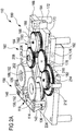
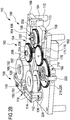
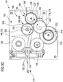
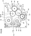
- FIGS Figures 1A and 1B Various perspective representations of an exemplary embodiment of a sample collection system 110 according to the invention are shown, the mode of operation of which is subsequently illustrated in FIG Figures 3A to 3D shown sequence is explained.
- the sample collection system 110 is preferably set up for operation with a tape cassette 158 for an analysis tape 114, which, for example, is analogous to the example in FIGS Figures 1A and 1B can be designed.
- This tape cassette 158 is in the Figures 2A to 2C however, it is only partially shown, so that, for example, the base plate 116 is not shown, since this would cover up other essential elements of the tape cassette 158. This base plate would fit into the Figures 2A to 2C located above the structure shown.
- the tape cassette 158 again comprises a good roll 120, a bad roll 146 as well as a roller system 136, a deflection system 142 and a coupling piece 150.
- the roller system 136 is shown in FIGS Figures 2A to 2C only shown in part and slightly different from that in the Figures 1A and 1B roller system 136 shown constructed. However, it is also possible analogously to use a roller system 136 according to FIGS Figures 1A and 1B to be used, in particular a roller system 136 with fixed rollers 138 and movable rollers 140, which prevent tension build-up within the analysis belt 114.
- a possible housing of the tape cassette 158 as well as further components of the sample collection system 110, such as an electronic control, as well as input means, display elements, data storage, evaluation devices for qualitative and / or quantitative analysis of the liquid sample, a housing of the sample collection system 110 or similar elements.
- the sample collection system 110 in FIGS Figures 2A to 2C further comprises a drive unit 160 for driving the functions of the sample collection system 110.
- the drive unit 160 in turn comprises an energy converter, which is preferably configured here as an electromechanical energy converter in the form of a motor 162 without restricting the possibilities of designing the energy converter.
- the motor 162 is preferably designed as an electric motor.
- the drive unit 160 further comprises a toothed gear 164, which is coupled to a coupling element 152.
- a connecting rod 166 as a connecting element, which connects to the coupling piece 150 and the deflection movement along the deflection direction 154 in FIGS Figures 1A and 1B can effect.
- the entire drive unit 160 is shown in FIGS Figures 2A to 2C illustrated embodiment applied to a base plate 168.
- the motor 162 is fixed in a motor guide 170 in the form of a slot in the base plate 168, such that a large part of the body of this motor 162 is arranged below the base plate 168 (that is to say on the side of the base plate 168 opposite the gear transmission 164) .
- the base plate 168 has supports 172, via which the base plate 168 can be mounted, for example, in a housing of the sample collection system 110.
- FIGS Figures 2A to 2C Embodiment of the assembly of the drive unit 160 illustrated by way of example, however, numerous other possibilities are conceivable for constructing or fixing this drive unit, so that the example is only intended to serve for illustration purposes.
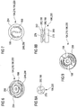
- Gear 164 includes a plurality of gears coupled together in various ways.
- the starting point is a motor gear 174 which functions as the first drive wheel and which is connected in a rotationally fixed manner to a motor axis 178 of the motor 162.
- This motor gear 174 is connected to a first drive train 180 and a second drive train 182, which drive different system functions.
- the first drive train 180 comprises a lancing drive gear 184, which engages directly in the motor gear 174 and thus rotates in the opposite direction to this motor gear 174.
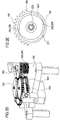
- the first drive train 180 further comprises a trigger gear 186 (only in FIGS Figures 2A and 2C shown, omitted in FIG. 2B), which is toothed only over almost half of its circumference and thus has a first, toothed circumferential region 188 and a second, toothless circumferential region 190.
- the trigger gear 186 is supported with the lancing drive gear on a common axis 192, but is not non-rotatably connected to this axis 192, but rather is only slidably mounted thereon.
- first direction-sensitive element 194 arranged between these elements in the form of a first freewheel 196.
- This first freewheel 196 is shown in the illustration Figure 2B , in which the trigger gear 186 has been omitted, and is likewise mounted on the axis 192 and is connected in a rotationally fixed manner to the lancing drive gear 184.
- the freewheel 196 has freewheel arms which, starting from the axis 192, extend spirally in a counterclockwise direction around this axis. These freewheel arms 198 or the ends of these freewheel arms 198 engage in (in the Figures 2A to 2C non-recognizable) drive pins or other designed drive elements on the underside of the trigger gear 196.
- the embodiment of the first direction-sensitive element 194 shown represents only one possibility for the configuration of such elements sensitive to the direction of rotation, which cause entrainment in one direction, but decoupling in another direction of rotation.
- other types of freewheels could also be used, for example freewheels with a higher number of freewheel arms 198 or another configuration of these freewheel arms.
- Freewheels with such freewheel arms 198 which can be configured, for example, as arms or prongs or pawls, are generally referred to as pawl freewheel arms in the context of the present invention.
- the first drive train 180 comprises a spike spring gear 202, which (at least in some angular positions) is in engagement with the trigger gear 186.
- This piercing spring gear 202 is connected in a rotationally fixed manner to a mechanical energy store 204 in the form of a spiral piercing spring 206.
- One end of this piercing spring 206 is connected to the piercing spring gear 202, whereas another end of this piercing spring 206 is stationary.
- the prong spring 206 is arranged about an axis 208 of the prong spring gear 202 in such a way that a clockwise rotation of the prong spring gear 202 causes tensioning of the prong spring 206 and thus a charging of the mechanical energy store 204, whereas a rotation of the prong spring gear 202 in the counterclockwise direction relaxes the pricking spring 206 and thus a discharge of the mechanical energy store 104.
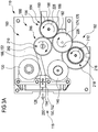
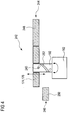
- a lock 200 is provided on the trigger gear 186, which is firmly connected to the base plate 168 and whose function is shown in FIG Figures 2D and 2E to be explained. It shows Figure 2D a partial perspective view of the first drive train 180, which illustrates that the lock 200 engages in the trigger gear 186.
- the lock 200 serves to prevent a sudden relaxation of this prong spring 206 by a rotation of the prong spring gear 202 (counterclockwise rotation) and the trigger gear 186 (clockwise rotation) in a tensioned state of the prong spring 206.
- the lock 200 is designed, for example, to be elastic (for example, as a leaf spring) and engages on the underside of the trigger gear 186 on a pawl 201 which protrudes on the circumference.
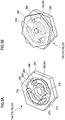
- This pawl 201 is in Figure 2E can be seen, which shows a view of the trigger gear 186 from below.
- the pawl 201 is arranged on the outside of a pawl ring 203, which is arranged on the underside of the trigger gear 186, that is to say on the side of this trigger gear 186 facing the freewheel arms 198.
- the pawl ring 203 On its inside, the pawl ring 203 has a tooth structure 154 with two teeth 256, which interact with the two freewheel arms 198 and form the first element 194 which is sensitive to the direction of rotation.
- the trigger gear 186 in this illustration has a bore 205 for receiving the axis 192.
- the pawl 201 is positioned on the circumferential side in such a way that it is held in the tensioned position of the piercing spring 206 (for example in a form-fitting manner) by the lock 200, so that only the trigger gear 186 can be rotated counterclockwise.
- the trigger mechanism is described in more detail below using the Figures 3A to 3D explained.
- the piercing spring gear 202 is connected via an eccentric bolt 210 to the connecting rod 166 of the coupling element 152, so that a rotary movement of the piercing spring gear 202 can be converted directly into a movement of the connecting rod 166, and thus, via the coupling piece 150, into a deflection of the in the application position 118 located analytical aids 112.
- these deflections can be configured differently for the different analytical aids 112, so that, for example, a different deflection (ie, eg a different deflection range) can take place for a lancet 128 than for a test element 122.
- This can in different ways, for example by using a link drive with different links for the lancet 128 and the test element 122.
- the positioning of the lancet 128 relative to the analysis tape 114 for example, also influences the penetration depth.
- Various other design variants are conceivable.
- the first drive train 180 thus essentially serves to deflect the analytical aid 112, for example for a lancing movement of a lancet 128 and / or a sampling movement of a test element 122.
- These different system functions are transmitted to the motor gear 174 and thus to the motor 162 by the first drive train 180 coupled. As described above, this coupling occurs only in the case where the motor gear 174 rotates clockwise.
- This drive train 182 initially comprises a winding drive gear 212 which is in engagement with the motor gear 174. If the motor gear 174 rotates clockwise, for example, the winding drive gear 212 rotates counterclockwise.
- a transport gear 216 is received on an axis 214 of the winding drive gear 212, but is not connected to the winding drive gear 212 in a rotationally fixed manner.
- the winding drive gear 212 and the transport gear 216 are connected to one another via a second direction-sensitive element 218, which in turn can be configured as a second freewheel 220 in this exemplary embodiment.
- a second direction-sensitive element 218 which in turn can be configured as a second freewheel 220 in this exemplary embodiment.
- a freewheel lock can also be provided to reduce lost motion and suppress noise Figure 2B is only indicated and which is designated by the reference number 222.
- the second freewheel 220 is configured in such a way that it only takes the transport gear 216 with it when the winding drive gear 212 rotates clockwise. If, however, the winding drive gear 212 rotates counterclockwise, there is no coupling between this winding drive gear 212 and the transport gear 216. Or, expressed in the direction of rotation of the motor gear 174, only this motor gear 174 is coupled to the transport gear 216 when the motor gear 174 turns counterclockwise.
- the second drive train 182 is therefore only coupled to the drive by the motor 162 when the motor gear 174 rotates counterclockwise, but is decoupled from the motor 162 when the motor 162 rotates clockwise.
- the transport gear 216 is again, for example, from Figure 2B can be seen in engagement with a winding gear 224.
- This winding gear 224 is non-rotatably (for example by means of teeth) connected to the bad winding 146 and drives it. Since in the illustrated embodiment of the drive unit 160 it is only possible to drive the transport gear 216 by the motor 162 in a clockwise direction, only a drive of the bad winding 146 in the counterclockwise direction is possible, that is to say a rotary movement of this bad winding 146, in which the analysis tape 114 is placed on this bad winding 146 is wound up. It should be pointed out here that, for example, in the Figures 2A to 2C illustrated embodiment of the sample collection system 110 only the bad winding 146 is driven.
- the starting point is the in Figure 3A illustrated situation of the sample collection system 110.
- the proposed method is preferably a cyclical method in which the individual method steps (operating phases) repeated in succession, it would equally be possible to carry out the method at another point, for example with Figure 3B to start.
- the starting point is in Figure 3A illustrated situation in which a lancet 128 is in the application position 118.
- the connecting rod 166 is arranged in such a way that it is in an upper position, in which the eccentric bolt 210 is arranged approximately in a 12 o'clock position of the piercing spring gear 202.
- the piercing spring 206 is tensioned, that is to say the mechanical energy store 204 is charged (in Figure 3A not recognizable, because covered by the spring gear 202).
- the trigger gear 186 is in a position in which the toothed peripheral region 188 just engages in the teeth of the piercing spring gear 202. Again, since the lock 200, as described above, holds the trigger gear 186 and prevents it from rotating clockwise, the piercing gear 202 is just held in the cocked position.
- the drive unit 160 drives the connecting rod 166 via the piercing spring gear 202, which in turn couples via the coupling piece 150 to the lancet 128 in the application position 118 and drives the latter into a deflected position.
- the lancet 128 is driven via the coupling element 152 into a lancing movement, which in Figure 3A is designated by the reference number 230.
- the eccentric pin 210 has reached its 9 o'clock position, the lancet 128 reaches its greatest deflection.
- the connecting rod 166 moves back again, since the piercing spring 206 continues to relax.
- the analysis tape 114 also moves back into its undeflected position.
- This return movement can, for example, take place actively by the coupling element 152 and / or can be driven in another way, for example by an internal tension of the analysis tape 114.
- an active coupling would also be possible, in which the backward movement of the lancet 128 or the analytical aid 112 would also be driven.
- This lancing movement 230 of the lancet 128 causes, for example, perforation of a skin area of a patient, as a result of which, for example, a drop of blood is generated.
- FIG. 3B A second operating phase of the sample collection system 110 is shown, which for example relates to the operating phase in FIG Figure 3A connects. While in the phase according Figure 3A the first drive train 180 was coupled to the motor gear 174 in order to initiate the system function of the lancing movement 230, is now in the in Figure 3B In the illustrated process, the second drive train 182 is coupled to the motor gear 174 in order to effect further transport of the analysis tape 114. During this sequence, the piercing spring 206 is in a relaxed position, in which the eccentric bolt 210 is in a 6 o'clock position. This relaxed position can be designed in a defined manner, for example by providing a defined stop and / or by applying a pretensioning force to the spring 206 206.
- the direction of rotation of the motor 162 is reversed, which can be done, for example, by a control by reversing the polarity of this motor 162. Accordingly, the motor gear 174 performs a counterclockwise rotation 232. Accordingly, the winding drive gear 212 rotates clockwise, which is shown in FIG Figure 3B is designated by the reference number 234. Because of the sensitivity to the direction of rotation of the second element sensitive to the direction of rotation, the winding drive gear 212 takes the transport gear 216 with it, so that this also performs the rotation 234 in a clockwise direction. The transport gear 216 engages the winding gear 224 as described above so that the bad winder 146 makes a counterclockwise rotation 236.
- the analysis tape 114 is wound on the bad winding 146.
- the duration of the rotation or the angle of rotation of the motor gear 174 (which can be done, for example, by controlling the sample collection system 110), this can result in exactly one test element 122 in the form of a test field 124 being moved into the application position 118.
- This is preferably the case of the in Figure 3A used Lancet 128 following test element 122 on the analysis tape 114.
- a clocking by exactly one analytical aid 112 can take place on the analysis tape 114.
- the first drive train 180 is decoupled from the motor gear 174 in this sequence, so that, for example, the spring gear 202 and the trigger gear 186 do not rotate.
- This in Figure 3B hidden) lancing drive gear 184 also rotates, but is decoupled from the trigger gear 186 via the first direction-sensitive element 194. This ensures that the connecting rod 166 does not change during this partial sequence 166.
- the result of in Figure 3B The partial sequence shown therefore consists in that a fresh analytical aid 112 in the form of a test element 122 with a test field 124 is again in the application position 118.
- the piercing spring 206 is relaxed, that is to say the energy store 204 is discharged.
- the direction of rotation of the motor gear 174 is used counterclockwise to couple the system function of continuing the analysis band 114 to the motor 162 via the second drive train 182.
- FIG. 3C A third partial sequence is shown, in which the first drive train 180 is in turn coupled to the engine 162.
- the motor 162 is actuated in such a way that it in turn rotates 226 clockwise, analogously to FIG Figure 3A .
- the winding drive gear 212 rotates counterclockwise, but the transport gear 216 is decoupled from it by the second direction-sensitive element 218 and is stationary.
- the analysis tape 114 thus remains in the position in which the test element 122 is in the application position 118.
- the first drive train 180 is coupled, since the motor gear 174 drives the lancing drive gear 184 to a rotation 228, which in turn drives the trigger gear 186 via the first direction-sensitive element 194. This entrainment takes place until the toothed peripheral region 188 of this trigger gear 186 engages again in the teeth of the prong spring gear 202 and drives it to rotate 238 in a clockwise direction.
- the piercing spring 206 is tensioned again, so that the mechanical energy store 204 is charged.
- the eccentric bolt 210 moves the connecting rod 166.
- the coupling piece 150 of the coupling element 152 again engages the analysis tape 114 and deflects the test element 122 in the application position 118.
- the test element 122 is in the deflected position Position.
- the test element 122 moves back to the undeflected position.
- This movement of the test element 122 can be used for sample collection.
- the test field 124 can perform a sampling movement 240, in which the test field 124 is moved towards a previously perforated area of skin, for example absorbing a drop of blood or another type of liquid sample, and then moving it back again.
- This sampling movement is thus gear-driven by the motor 174.
- This sampling movement 240 is thus considerably slower than the previous deflection of the analysis tape 114 during the lancing movement 230, which is advantageous for the sampling. In this way it can be ensured that a sufficient amount of the liquid sample is applied to the test field 124.
- the piercing spring 206 is again in the tensioned position, analogous to FIG Figure 3A , and a liquid sample was applied to the test field 124 in the application position 118.
- This partial sequence can be followed by a partial sequence (not shown) in which the sample is evaluated qualitatively and / or quantitatively.
- the test field 124 in the application position 118 can be illuminated with light, and by means of suitable detectors, for example, color changes in a test chemistry of the test field 124 can be determined, from which in turn an analyte concentration (for example a blood glucose concentration) in the liquid sample can be concluded can be.
- an electrochemical evaluation is also possible, for example by making electrical contact with the analysis tape 114 or the test field 124.
- the analyte concentration can advantageously also be measured in a different position than in the application position 118.
- at least one separate measurement position could be provided, into which the test field 124 is moved (for example in the context of a subsequent method step), and in which this test field 124 is evaluated, for example optically and / or electrochemically.
- This transport of the test field 124 into the measuring position could, for example, be based on the following Figure 3D described transport step take place or could be implemented as part of a separate transport step.
- the result of the partial transport sequence according to Figure 3D is again the starting point of the partial sequence in Figure 3A .
- the cycle of the partial sequences can accordingly start again, for example to carry out a new analysis.
- the use of the freewheels 196, 220 is only one possibility of realizing elements 194, 218 which are sensitive to the direction of rotation.
- a further possibility of realizing a direction-sensitive element 242 is exemplified in Figure 4 shown. Again, a motor 162 is used which drives a motor axis 192. A first drive wheel 176 in the form of a motor gear 174 sits on this axis 192.
- this motor gear 174 is connected to the axis 192 via a bolt 243 in such a way that this motor gear 174 can move on two planes 244, 246.
- a first drive level 244 (which in Figure 4 is arranged at the top)
- the motor gear 174 is in engagement with a drive element 248 of a first drive train
- the second drive plane 246 (in Figure 4 below)
- the motor gear 174 is engaged with a drive element 250 of a second drive train.
- the two drive trains need not necessarily be identical to the drive trains 180, 182 of the exemplary embodiment according to the Figures 3A to 3D , but can also be exchanged for example.
- the arrangement of the motor gear 174 on the two levels 244, 246 is brought about by a groove 252 arranged on the circumference in the axis 192.
- the bolt 243 is received in this groove 252.
- rotation of the axis 192 in the counterclockwise direction (viewed in FIG Figure 4 from above onto the axis 192) the motor gear 174 is "screwed down" to the second drive level 146, whereas a clockwise rotation of the axis 192 causes the motor gear 174 to be arranged on the first drive level 244 and thus engages in the drive element 248 of the first drive train .
- the groove 252 is designed in accordance with a screw curve.
- the drive elements 248, 250 of the two drive trains can, for example, in turn be designed as gear wheels. However, other configurations are also conceivable.
- one of the freewheels 196, 220 shown is rotated faster on one drive side in one working direction than on an output side, then a driver in the form of freewheel arms 198 reaches for a construction-specific angle of rotation, the lost motion, and transmits a maximum torque to the output side. If the maximum torque is exceeded, the freewheel 196, 220 is destroyed. If the drive side rotates in the opposite direction to the working direction, only a minimal torque, the idling torque, is transmitted to the output side.
- the freewheels 196, 220 suitable for the present sample collection system 110 could, for example, transmit torques up to approx. 100 mNm and have an idling torque which is approximately 0 mNm.
- the freewheels 196, 220 should have a small size, a simple structure, a robust construction and a low lost motion and should work quietly.
- FIG. 5A and 5B shows a first freewheel 196, 220 in various perspective views, which is based on a freewheel in an automatic watch.
- This freewheel is designed for torques of over 100 mNm and has a vanishingly low idle torque ( ⁇ 1 mNm).
- the rocker arm 264 is asymmetrically shaped and interacts with a tooth structure 254 on the driven side 262.
- the rocker arms 264 slide over flat flanks 268 of this tooth structure 254 without driving the output side 262.
- driving ends 270 of the rocker arms 264 are pressed against steep flanks 272 of the tooth structure 254 and take the driven side 262 with them.
- a second tooth structure 274 in the interior of the driven side 262 ensures that the curved rocker arms 264 always optimally contact the outer tooth structure 254.
- the tooth structure 254 and the second tooth structure 274 together form a channel 275 in which the rocker arms 264 run.
- the rocker arm construction according to the Figures 5A and 5B has some advantages over other types of freewheels, which are particularly advantageous for medical applications.
- the extremely low idle torque has already been mentioned.
- a lubricant is not applied to the freewheel 198, 264, since such lubricants cause a torque even in the idling direction due to their toughness.
- smooth-running materials can be used, in particular plastics such as polyamide and / or polyacetal (POM).
- plastics such as polyamide and / or polyacetal (POM).
- metal parts can also be used. Metal parts that are produced by a laser sintering process are particularly suitable here.
- FIG. 6 An embodiment of a freewheel 196, 220 is shown, which essentially corresponds to the freewheel 196 in Figure 2B corresponds.
- the freewheel 196, 220 has two freewheel arms 198, which in one working direction (in Figure 6 a rotation of the arms to 196 in the clockwise direction) engage in a tooth structure 254 of a drive element 248, 250 to be driven. However, there is no entrainment in the opposite direction, since the freewheel arms 198 slide over the tooth structure 254.
- the tooth structure 254 in the example of FIG Figure 6 here has two teeth 256.
- the freewheel according to Figure 6 is designed for a maximum torque of approx. 75 mNm and has an idle torque of approx. 11 mNm.
- Figure 7 is a too Figure 6 alternative embodiment of a freewheel 196, 220 shown.
- the freewheel 196, 220 has two freewheel arms 198, which in this exemplary embodiment likewise slide over a tooth structure 254 of the drive element 248, 250 to be driven.
- the direction of entrainment is a direction of rotation of the freewheel arms 198 in the counterclockwise direction.
- a larger number of teeth 256 is provided, which results in less lost motion.
- the freewheel 196, 220 according to FIG. 7 is designed for a maximum torque of approx. 20 mNm.
- FIGs 8A and 8B Another variant of a freewheel 196, 220 is shown, which can preferably be made entirely of sheet steel.
- an input side 260 and an output side 262 are provided, which in this example are each made of circular steel sheet disks.
- Figure 8A is a Top view of the output side 262 shown, whereas Figure 8B shows the freewheel 196, 220 in a side view.
- the disks each have a bore 276 or 278.
- Freewheel arms 198 which are oriented in opposite directions, are punched out of the disks in the form of driver levers 280, 282, which have the form of tongues.
- driver levers 280, 282 which have the form of tongues.
- four such driver levers 280, 282 are provided, but this does not rule out an embodiment with a different number.
- the drive side 260 rotates counterclockwise in Figure 8A
- these tongue-shaped driver levers 280, 282 slide over one another so that there is no entrainment (idling).
- the driver levers 280, 282 become caught in one another and take-along takes place.
- the variant shown allows a particularly flat construction and is designed with two driver levers 198 for a maximum torque of 50 mNm and an idling torque of approximately 2.8 mNm.
- the freewheel 196, 220 is designed for a maximum torque of approximately 100 mNm and an idling torque of approximately 5.6 mNm.
- FIG 9 Another exemplary embodiment of a freewheel 196, 220 according to the invention is shown.
- the freewheel arms 198 are greatly shortened compared to the freewheel arms in the previous exemplary embodiments and represent a gearwheel structure with 8 teeth.
- Two driver arms 258 engage in these freewheel arms 198. These driver arms have the effect that when the freewheel 196, 220 is rotated clockwise, the driver arms 258 are carried along, but not in the counterclockwise direction.
- the freewheel 196, 220 according to Figure 9 is with 2 driver arms 258, that means as in Figure 9 shown, designed for a maximum torque of 25 mNm and an idle torque of approx.4.4 mNm, and in a variant not shown with four driver arms 258 for a maximum torque of approx. 40 mNm and an idle torque of approx.6.6 mNm .
- sample collection system 110 includes at least one system function to which is coupled, ie a transport function, namely the drive of the bad winding 146.
- This drive takes place, as for example in Figure 2B recognizable, via the winding gear 224.
- the winding drive can be coupled to the bad winding 146, for example rigidly, for example by the bad winding 146, for example as part of a tape cassette 158, being rotatably mounted on this winding drive.
- slip clutches can also be used, which can be part of the drive unit 160, for example part of the winding drive. Examples of such slip clutches are in the Figures 10 to 12 shown, which will be explained below.
- the slip clutches are generally designated there with the reference number 284.
- winding wheel 286 is shown of the bad winding 146 in order to allow a view of the slip clutch 284.
- the winding wheel 286 is driven by a winding drive 288, which is part of the drive unit 160 and which can comprise, for example, the winding gear 224.
- This winding drive 288 drives the winding wheel 286, on which in turn the analysis tape 114 (not shown in the figures) with the used test elements 122 and / or lancets 128 can be wound up.
- the winding wheel 286 can be directly part of the bad winding 146. Alternatively, the bad winding 146 can, however, only be seated on this winding wheel 286.
- the slip clutch 284 is only part of the drive unit 160 and comprises elements of the winding wheel 286 and the winding drive 288 Figure 10
- the slip clutch 284 comprises a spiral spring element 292 which is connected to a central hub 290 of the winding drive 288 and which can be produced, for example, from a metallic material, for example spring steel.
- a metallic material for example spring steel.
- other materials for example plastic materials, can also be used in principle.
- the slip clutch 284 may include other types of spring elements.
- the spiral spring element 292 ends in a curved end 294, which acts as a first engagement element 296.
- These second engaging elements 298 are shown in FIG Figure 10 embodiment shown designed in the form of ramp-shaped teeth 300. Another configuration of these second engagement elements 298 is also possible in principle.
- the first engagement element 296 initially engages in the second engagement elements 298.
- the number of teeth 300 distributed over the inner circumference of the winding wheel 286 should be chosen to be as large as possible in order to achieve the least possible idling. In the exemplary embodiment shown, eleven teeth 300 are provided, although in principle a different number of teeth 300 is also possible.
- the spiral spring element 292 takes the winding wheel 286 with it during the said rotation in the direction of rotation 312 by engagement of the engagement elements 296, 298 until a desired positioning of the analysis tape 114 is achieved.
- This positioning can consist, for example, of a specific test field 124 and / or a specific lancet 128, for example the next lancet 128 and / or the next test field 124, having reached the application position 118 and / or a measurement position.
- a blocking element for example, can be provided in this application position 118 and / or measuring position, which prevents and / or complicates further transport of the analysis tape 114.
- This blocking element can in turn comprise, for example, at least one first engagement element, which is firmly connected to the sample collection system, and a second engagement element, which is connected to the analysis tape 114, the two engagement elements engaging in one another and a further transport when the desired application position and / or measurement position is reached prevent.
- a gripper or another type of blocking element is also conceivable.
- the blocking element then exerts a force on the analysis tape 114, which in this case corresponds to a holding force. At the winding drive 288, this holding force is converted into a torque which counteracts the drive torque of the winding drive 288.
- the spiral spring element 292 then contracts up to a defined maximum torque.
- This maximum torque is due to the fact that, when interacting, the curved end 294 of the spiral spring element 292 moves radially inward until the teeth 300 are no longer carried. From this torque, the first engagement element 296 reaches out of the second engagement elements 298, and the slip clutch 284 opens. The curved end 294 of the spiral spring element 292 now slips over the teeth 300 on the winding wheel 286 and thus decouples the drive unit 160 from the bad winding 146, so that the transport function is no longer carried out. This on the one hand prevents further transport of the analysis tape 114 into incorrect positioning, and on the other hand also prevents damage to the analysis tape 114, the blocking element (for example a gripper) and / or the drive unit 160. Furthermore, the changed drive conditions described above can be compensated in this way for different degrees of winding of the bad winding 146.
- the spiral spring element 292 can comprise a metallic spiral spring element and / or a plastic spiral spring element, which can be fastened to the central hub 290 and / or another element of the winding drive 288, for example in a form-fitting, force-fitting or material-locking manner.
- the spring element can also be received on the element to be driven, so that a reversal of the in Figure 10 shown principle can be done.
- the winding drive 288 can include the second engagement elements 298, for example in the form of the teeth 300, and the winding wheel 286 to be driven includes the spring element, for example the spiral spring element 292, with the first engagement element 296.
- a plurality of engagement elements 296 is also conceivable.
- the spiral spring element 292 according to the exemplary embodiment is in FIG Figure 10 replaced by spring elements 304, which in this case comprise a spring arm 306.
- the exemplary embodiments differ according to the Figures 11 and 12th in the number of these spring elements 304 or spring arms 306. While in the embodiment according to Figure 11 only one spring arm 306 is provided in the exemplary embodiment according to FIG Figure 12 several spring arms 306 available.
- the spring arms 306 can, for example, like other components of the slip clutches 184, be made of a metallic material and / or a plastic material. However, other materials, in particular materials with elastic properties, can also be used in principle.
- Three spring arms 306 are evenly distributed along the periphery of the central hub 290 and connected to it. A different number and / or arrangement of the spring arms 306 is in principle also possible.
- first engagement elements 296 are again provided.
- these first engagement elements 296 comprise projections 308 projecting radially from the spring arms 306.
- another configuration of the first engagement elements 296 is also possible in principle.
- the first engagement elements 296 in the form of the projections 308 in turn interact with second engagement elements 298 in the form of teeth 300 arranged on the inner circumference of the winding wheel 286.
- these teeth 300 may in turn be ramp-shaped, the outer surface of the projections 308 being chamfered, for example, and thus essentially parallel to the ramp surfaces of the teeth 300 can be configured.
- a non-parallel arrangement is also possible in principle.
- the effect of the slip clutches 284 according to the Figures 11 and 12th is basically similar to that based on Figure 10 described effect.
- the teeth 300 of the winding wheel 286 are entrained by the projections 308 up to a maximum torque.
- the spring arms 306 are bent inwards and the projections 308 move radially inwards. From a maximum torque at which the projections 308 no longer engage the teeth 300 or the winding wheel 286 is carried along, the transport function is then interrupted. Again, this maximum torque can be provided, for example, by one or more blocking elements, for example a gripper, which holds the analysis tape 114 in a desired position.
- Slip clutches 284 shown only represent possible embodiments of such slipping clutches.
- the possibility of using a slipping clutch 284 for coupling to the winding wheel 286 and its transport function is only one of many possibilities for the useful use of such slipping clutches 284 in FIGS Sample collection systems 110.
- one or more other system functions can also be coupled via one or more slip clutches 284, for example.
- the drive unit 160 can also include one or more slip clutches 284 for other purposes, for example in driving the coupling element 152 and / or when coupling to the energy converter 162.
- a slip clutch 284 can also be profitable when coupling to the energy converter 162 are used, for example to avoid damage to the drive unit 160 and / or other elements in the event of a malfunction of the energy converter 162.
- a slip clutch 284 can also be used, for example, when coupling to the mechanical energy store 204, for example in order to avoid over-tensioning a piercing spring 206 and thereby damaging the same.
- Various other configurations are conceivable.
Description
Die Erfindung betrifft ein Probengewinnungssystem zum Gewinnen einer flüssigen Probe mittels mindestens eines analytischen Hilfsmittels. Die Erfindung betrifft weiterhin ein Verfahren zum Gewinnen einer flüssigen Probe. Derartige Probengewinnungssysteme und Verfahren werden insbesondere in der medizinischen Diagnostik im Krankenhausbereich, im Bereich von Pflegeheimen oder im Rahmen eines Home-Monitoring Konzeptes eingesetzt, um die Konzentration mindestens eines Analyten, beispielsweise eines Metaboliten und insbesondere von Blutglucose, in einer Körperflüssigkeit zu bestimmen.The invention relates to a sample extraction system for collecting a liquid sample using at least one analytical aid. The invention further relates to a method for obtaining a liquid sample. Such sample collection systems and methods are used in particular in medical diagnostics in hospitals, in the area of nursing homes or in the context of a home monitoring concept in order to determine the concentration in at least one analyte, for example a metabolite and in particular blood glucose, in a body fluid.
Die Untersuchung von Blutproben oder anderen Proben von Körperflüssigkeit, wie beispielsweise von interstitieller Flüssigkeit, ermöglichen in der klinischen Diagnostik das frühzeitige und zuverlässige Erkennen von pathologischen Zuständen sowie die gezielte und fundierte Kontrolle von Körperzuständen. Die medizinische Diagnostik setzt in der Regel die Gewinnung einer Probe aus Blut oder interstitieller Flüssigkeit des zu untersuchenden Individuums voraus.In clinical diagnostics, the examination of blood samples or other samples of body fluid, such as interstitial fluid, enables the early and reliable detection of pathological conditions as well as the targeted and well-founded control of body conditions. Medical diagnostics generally require the taking of a sample from the blood or interstitial fluid of the individual to be examined.
Zur Gewinnung der Probe kann die Haut z. B. an der Fingerbeere oder dem Ohrläppchen der zu untersuchenden Person mit Hilfe einer sterilen, spitzen oder scharfen Lanzette perforiert werden, um so einige wenige Mikroliter Blut oder weniger für die Analyse zu gewinnen. Insbesondere eignet sich diese Methode für die Analyse einer Probe, die unmittelbar nach der Probengewinnung durchgeführt wird.To obtain the sample, the skin can e.g. B. on the fingertip or the earlobe of the person to be examined with the aid of a sterile, pointed or sharp lancet, so as to collect a few microliters of blood or less for analysis. This method is particularly suitable for the analysis of a sample that is carried out immediately after the sample has been obtained.
Vor allem im Bereich des so genannten "Home-Monitoring", also dort, wo medizinische Laien selbst einfache Analysen des Bluts oder der interstitiellen Flüssigkeit durchführen, und dort insbesondere für die regelmäßige, mehrmals täglich durchzuführende Blutgewinnung durch Diabetiker für die Kontrolle der Blutglukosekonzentration, werden Lanzetten und dazu passende Geräte (so genannte Stechhilfen) angeboten, die eine möglichst schmerzarme und reproduzierbare Probengewinnung ermöglichen. Solche Lanzetten und Geräte (Stechhilfen) sind z. B. Gegenstand von
Die eigenhändige Blutzuckerbestimmung ist heute eine weltweit verbreitete Methode in der Diabetes-Kontrolle. Blutzuckergeräte im Stand der Technik weisen in der Regel ein Analysegerät auf, in das ein Testelement (Teststreifen) eingeführt wird. Das Testelement wird mit einem Tropfen einer Probe in Kontakt gebracht, der zuvor mittels einer Stechhilfe z. B. aus der Fingerbeere gewonnen wurde.Handwritten blood sugar determination is a method used worldwide in diabetes control today. Blood sugar devices in the prior art generally have an analysis device into which a test element (test strip) is inserted. The test element is brought into contact with a drop of a sample, which was previously z. B. was obtained from the fingertip.
Zur Analyse von Flüssigproben, beispielsweise Körperflüssigkeiten wie Blut oder Urin, werden häufig Analysegeräte verwendet, bei denen sich die zu analysierende Probe auf einem Testfeld eines Testelements befindet und in dem Testfeld gegebenenfalls mit einer oder mehreren Reagenzien reagiert, bevor sie analysiert wird. Die optische, insbesondere photometrische, und die elektrochemische Auswertung von Testelementen stellen die gebräuchlichsten Verfahren zur schnellen Bestimmung der Konzentration von Analyten in Proben dar. Analysesysteme mit Testelementen zur Probenanalyse werden allgemein im Bereich der Analytik, der Umweltanalytik und vor allem im Bereich der medizinischen Diagnostik eingesetzt. Insbesondere im Bereich der Blutglukosediagnostik aus Kapillarblut besitzen Testelemente, die photometrisch oder elektrochemisch ausgewertet werden, einen großen Stellenwert.For analyzing liquid samples, for example body fluids such as blood or urine, analysis devices are frequently used, in which the sample to be analyzed is located on a test field of a test element and, if appropriate, reacts in the test field with one or more reagents before it is analyzed. The optical, in particular photometric, and the electrochemical evaluation of test elements are the most common methods for quickly determining the concentration of analytes in samples. Analysis systems with test elements for sample analysis are generally used in the field of analysis, environmental analysis and, above all, in the field of medical diagnostics . Particularly in the field of blood glucose diagnostics from capillary blood, test elements that are evaluated photometrically or electrochemically are of great importance.
Es gibt verschiedene Formen von Testelementen. Bekannt sind zum Beispiel im Wesentlichen quadratische Plättchen, die auch als Slides bezeichnet werden, in deren Mitte sich ein mehrschichtiges Testfeld befindet. Diagnostische Testelemente, die streifenförmig ausgebildet sind, werden als Teststreifen bezeichnet. Im Stand der Technik sind Testelemente umfassend beschrieben, beispielsweise in den Dokumenten
Weitere im Stand der Technik bekannte mehrschichtige Testelemente sind Analysebänder mit einer Vielzahl von Testfeldern, die in einer Kassette aufgewickelt zur Verwendung in einem Analysegerät bereitgestellt werden. Solche Kassetten und Analysebänder werden zum Beispiel in den Dokumenten
Die zahlreichen Systemkomponenten (Lanzette, Stechhilfe, Testelement und Analysegerät) benötigen viel Platz und bedingen eine relativ komplexe Handhabung. Inzwischen gibt es auch Systeme mit einem höheren Grad der Integration und damit einer einfacheren Handhabung, bei denen z. B. die Testelemente im Analysegerät magaziniert und für die Messung zur Verfügung gestellt werden. Ein nächster Schritt der Miniaturisierung ist beispielsweise durch die Integration von mehreren Funktionen beziehungsweise Funktionselementen in einem einzigen analytischen Hilfsmittel (Disposable) zu erreichen. Durch geeignete Kombination von Stechvorgang und sensorischer Analytkonzentrations-Erfassung auf einem Testelement lässt sich beispielsweise der Bedienablauf deutlich vereinfachen.The numerous system components (lancet, lancing device, test element and analysis device) require a lot of space and require a relatively complex handling. There are now also systems with a higher degree of integration and thus easier handling, in which, for. B. the test elements are stored in the analyzer and made available for the measurement. A next step in miniaturization can be achieved, for example, by integrating several functions or functional elements in a single analytical aid (disposable). The operating sequence can be significantly simplified, for example, by a suitable combination of the lancing process and sensory analyte concentration detection on a test element.
Aus
Aus
Für integrierte Messsysteme spielt die Baugröße eine besondere Rolle. Ein Ziel integrierter Systeme muss es sein, ein Gerät bereitzustellen, das nicht viel größer ist als die bisherigen, nicht-integrierten Systeme. Ein Ansatz in dieser Richtung besteht darin, Kombinationsantriebe zu verwenden, bei welchen ein Bewegungsablauf mehrere Funktionen übernimmt. So ist beispielsweise aus
Die in
Aus
Ein weiteres Probengewinnungssystem zum Gewinnen einer Körperflüssigkeit ist in der
Es ist daher eine Aufgabe der vorliegenden Erfindung, ein Probengewinnungssystem, insbesondere ein Probengewinnungssystem gemäß der obigen Beschreibung, bereitzustellen, welches zum Gewinnen einer flüssigen Probe, insbesondere einer Körperflüssigkeit, geeignet ist und welches die Nachteile der bekannten Systeme vermeidet. Insbesondere soll das Probengewinnungssystem einen hohen Integrationsgrad aufweisen und einen einfachen und störungsunanfälligen Kombinationsantrieb für verschiedene Systemfunktionen des Probengewinnungssystems bereitstellen.It is therefore an object of the present invention to provide a sample collection system, in particular a sample collection system as described above, which is suitable for obtaining a liquid sample, in particular a body fluid, and which avoids the disadvantages of the known systems. In particular, the sample collection system should have a high degree of integration and provide a simple and trouble-free combination drive for various system functions of the sample collection system.
Diese Aufgabe wird gelöst mittels eines Probengewinnungssystems mit den Merkmalen des Anspruchs 1. Vorteilhafte Weiterbildungen der Erfindung, welche einzeln und in Kombination realisiert werden können, sind in den abhängigen Ansprüchen dargestellt. Der Wortlaut sämtlicher Ansprüche wird hiermit zum Inhalt der Beschreibung gemacht.This object is achieved by means of a sample collection system with the features of claim 1. Advantageous further developments of the invention, which can be implemented individually and in combination, are presented in the dependent claims. The wording of all claims is hereby made the content of the description.
Das vorgeschlagene Probengewinnungssystem soll eingerichtet sein, um insbesondere für einen Analytnachweis, wie beispielsweise einen qualitativen und/oder quantitativen Nachweis von Blutglukose, eine flüssige Probe, insbesondere eine Körperflüssigkeit, zu gewinnen. Dabei ist unter einem "Probengewinnungssystem" ein System zu verstehen, welches eingerichtet ist, um diese flüssige Probe zu erzeugen und/oder die flüssige Probe aufzunehmen und/oder die aufgenommene Probe zumindest teilweise bereits zu verarbeiten, das heißt ganz oder teilweise zu analysieren. Der Begriffsinhalt des Begriffs "Probengewinnungssystem" ist insofern weit zu fassen.The proposed sample collection system should be set up to obtain a liquid sample, in particular a body fluid, in particular for an analyte detection, such as a qualitative and / or quantitative detection of blood glucose. In this context, a “sample collection system” is to be understood as a system which is set up to generate this liquid sample and / or to take up the liquid sample and / or to at least partially process the received sample, that is to say to analyze it in whole or in part. The conceptual content of the term "sample collection system" is therefore broad.
Das Probengewinnungssystem umfasst mindestens ein analytisches Hilfsmittel. Dieses analytische Hilfsmittel kann beispielsweise die Probenaufhahme, die Probenerzeugung, die Analyse der Probe, eine Kombination dieser Funktionen oder ähnliche Aufgaben übernehmen. Besonders bevorzugt ist es dabei, wenn das analytische Hilfsmittel mindestens eine Lanzette und/oder mindestens ein Testelement mit mindestens einem Testfeld zur Analyse der flüssigen Probe aufweist. Beispielsweise kann es sich bei der Lanzette um eine Lanzettennadel oder um eine Lanzette mit einem scharfkantigen Element handeln, welches beispielsweise für die Perforation einer Hautpartie im Bereich der Fingerbeere und/oder des Ohrläppchens geeignet ist. Das Testelement kann beispielsweise gemäß einem der oben beschriebenen Testelemente ausgestaltet sein und kann beispielsweise ein Testfeld für einen optischen Analytnachweis und/oder für einen elektrochemischen Analytnachweis, jeweils mittels einer geeigneten Testchemie, umfassen.The sample collection system includes at least one analytical tool. This analytical aid can, for example, take over the sample collection, the sample generation, the analysis of the sample, a combination of these functions or similar tasks. It is particularly preferred if the analytical device has at least one lancet and / or at least one test element with at least one test field for analyzing the liquid sample. For example, the lancet can be a lancet needle or a lancet with a sharp-edged element, which is suitable, for example, for the perforation of a skin area in the area of the fingertip and / or the earlobe. The test element can be configured, for example, according to one of the test elements described above and can, for example, comprise a test field for optical analyte detection and / or for electrochemical analyte detection, in each case by means of a suitable test chemistry.
Besonders bevorzugt ist es dabei, wenn mehrere analytische Hilfsmittel vorgesehen sind oder ein analytisches Hilfsmittel, welches eine Mehrzahl von Untereinheiten analytischer Hilfsmittel (beispielsweise eine Mehrzahl von Lanzetten und/oder eine Mehrzahl von Testelementen) umfasst. Beispielsweise kann das Probengewinnungssystem zur Aufnahme und Bereitstellung mehrerer analytischer Testelemente geeignete Elemente umfassen, beispielsweise ein Magazin, insbesondere ein Trommelmagazin, ein Stangenmagazin, ein Reihenmagazin oder Zickzackmagazin, ein Analyseband mit einer Vielzahl von analytischen Hilfsmitteln, eine Analysescheibe, auf welcher mehrere analytische Hilfsmittel angeordnet sind oder ähnliche Elemente, welche die Bereitstellung und Verwendung einer Vielzahl dieser analytischen Hilfsmittel ermöglichen. Besonders bevorzugt ist es im Rahmen der vorliegenden Erfindung, wenn das analytische Hilfsmittel ein Analyseband aufweist, wobei auf dem Analyseband eine Vielzahl von Lanzetten und/oder Testfeldern angeordnet sind. Dabei ist es wiederum bevorzugt, wenn Lanzetten und Testfelder alternierend angeordnet sind, so dass beispielsweise jeweils einer Lanzette ein nachgeordnetes Testfeld zugeordnet ist. Auch Bänder, welche ausschließlich Lanzetten aufweisen, sowie Bänder, welche ausschließlich Testfelder aufweisen, sind im Rahmen der Erfindung anwendbar. Analysebänder mit hierauf angeordneten Lanzetten sind auch als "lancet on tape"-(LOT-)Analysebänder bekannt. Dabei ist der Begriff "Band" im Zusammenhang mit "Analyseband" vorzugsweise dahingehend zu verstehen, dass dieses Analyseband einen kontinuierlichen Trägerstreifen umfasst, beispielsweise einen Trägerstreifen aus einem Polymermaterial (zum Beispiel eine Polyesterfolie), einem Papiermaterial oder einem Verbundmaterial. Der Begriff "Band" ist jedoch nicht auf durchgehende Bänder beschränkt, sondern umfasst prinzipiell jegliche serielle Verbindungstechnik benachbarter analytischer Hilfsmittel, wie beispielsweise Lanzetten und/oder Testelemente, welche eine serielle Zufuhr dieser analytischen Hilfsmittel in eine Applikationsposition beinhaltet. So sind beispielsweise Gliederketten, Haken- und Ösenverbindungen, Verbindungen über Zwischenglieder oder ähnliche Arten von seriellen Verbindungen zwischen benachbarten analytischen Hilfsmitteln von diesem Begriff mit umfasst. Es sei weiterhin darauf hingewiesen, dass die Erfindung jedoch nicht auf die Verwendung von Analysebändern beschränkt ist, sondern dass diese beispielsweise auch für andere Methoden der Bereitstellung von analytischen Hilfsmitteln eingesetzt werden kann.It is particularly preferred if a plurality of analytical aids are provided or an analytical aid which comprises a plurality of subunits of analytical aids (for example a plurality of lancets and / or a plurality of test elements). For example, the sample collection system can include suitable elements for receiving and providing several analytical test elements, for example a magazine, in particular a drum magazine, a rod magazine, a series magazine or zigzag magazine, an analysis tape with a large number of analytical aids, an analysis disk on which several analytical aids are arranged or similar elements that allow the provision and use of a variety of these analytical tools. In the context of the present invention, it is particularly preferred if the analytical aid has an analysis tape, a large number of lancets and / or test fields being arranged on the analysis tape. It is again preferred if lancets and test fields are arranged alternately, so that, for example, a downstream test field is assigned to each lancet. Bands which only have lancets and bands which only have test fields can also be used within the scope of the invention. Analysis tapes with lancets arranged thereon are also known as "lancet on tape" (LOT) analysis tapes. The term “tape” in connection with “analysis tape” should preferably be understood to mean that this analysis tape comprises a continuous carrier strip, for example a carrier strip made of a polymer material (for example a polyester film), a paper material or a composite material. However, the term “tape” is not limited to continuous tapes, but in principle encompasses any serial connection technology of adjacent analytical aids, such as lancets and / or test elements, which includes a serial feed of these analytical aids into an application position. For example, link chains, hook and eye connections, connections via intermediate links or similar types of serial connections between adjacent analytical aids encompassed by this term. It should also be pointed out that the invention is not limited to the use of analysis tapes, but that it can also be used, for example, for other methods of providing analytical aids.
Das Probengewinnungssystem umfasst ein Kopplungselement zur Ankopplung an das analytische Hilfsmittel, sowie mindestens eine Antriebseinheit zum Antreiben einer Bewegung des Kopplungselements aus einer Ruheposition in eine ausgelenkte Position. Die Ankopplung erfolgt dabei vorzugsweise derart, dass nach der Verwendung des analytischen Hilfsmittels (beispielsweise einer Lanzette) wiederum eine Abkopplung von diesem erfolgt, so dass anschließend erneut an ein nächstes analytisches Hilfsmittel angekoppelt werden kann, beispielsweise ein Testelement, beispielsweise ein auf demselben Analyseband wie die zuvor verwendete Lanzette angeordnetes Testelement.The sample extraction system comprises a coupling element for coupling to the analytical aid, as well as at least one drive unit for driving a movement of the coupling element from a rest position into a deflected position. The coupling is preferably carried out in such a way that after use of the analytical aid (for example a lancet) there is again a decoupling from it so that it can then be coupled again to a next analytical aid, for example a test element, for example one on the same analysis tape as that Test element arranged previously used lancet.
Unter einer Kopplung oder einem Ankoppeln kann dabei insbesondere eine Herstellung eines physikalischen Kontaktes verstanden werden, und unter einer Abkopplung die Aufgabe oder Trennung dieses Kontaktes. Das Kopplungselement kann aktiv und/oder passiv an das analytische Hilfsmittel in der Applikationsposition ankoppeln und kann hierdurch bewirken, dass dieses analytische Hilfsmittel ebenfalls eine Bewegung um einen definierten Weg in eine oder mehrere ausgelenkte Positionen durchführt. Dabei können für unterschiedliche Arten analytischer Hilfsmittel unterschiedliche ausgelenkte Positionen vorgesehen sein, beispielsweise eine ausgelenkte Position für eine Probenaufhahme mittels eines Testelements und eine ausgelenkte Position für eine Stechbewegung einer Lanzette.Coupling or coupling can be understood to mean in particular the establishment of a physical contact, and decoupling the task or separation of this contact. The coupling element can actively and / or passively couple to the analytical aid in the application position and can thereby cause this analytical aid to likewise perform a movement by a defined path into one or more deflected positions. In this case, different deflected positions can be provided for different types of analytical aids, for example a deflected position for sampling by means of a test element and a deflected position for a lancing movement of a lancet.
Unter einer "aktiven" Kopplung können dabei verschiedene Arten der Kopplung des Kopplungselements mit dem analytischen Hilfsmittel zu verstehen sein. So kann beispielsweise das Kopplungselement das analytische Hilfsmittel aktiv greifen, beispielsweise mittels eines Greifers und/oder eines auf andere Weise gestalteten Öffnungs- oder Schließmechanismus, welcher ein aktives An- und Abkoppeln erlaubt. Im Gegensatz hierzu wird in diesem Sinne unter einer passiven Kopplung eine Kopplung ohne aktives Öffnen oder Schließen verstanden, also beispielsweise eine einfache Ausübung einer Kraft durch das Kopplungselement auf das analytische Hilfsmittel oder ein Ankoppeln mittels Widerhaken.An “active” coupling can be understood to mean different types of coupling of the coupling element to the analytical aid. For example, the coupling element can actively grip the analytical aid, for example by means of a gripper and / or an opening or closing mechanism designed in another way, which allows active coupling and uncoupling. In contrast to this, a passive coupling is understood to mean a coupling without active opening or closing, that is to say, for example, a simple exertion of a force by the coupling element on the analytical aid or a coupling using barbs.
Auch in einem anderen Sinne kann eine aktive oder eine passive Kopplung verstanden werden, wobei wiederum beide Möglichkeiten realisierbar sind, nämlich im Sinne eines aktiven oder passiven Antriebs des analytischen Hilfsmittels durch das Kopplungselement. Unter einer aktiven Kopplung kann dabei eine Kopplung verstanden werden, bei welcher das Kopplungselement an das analytische Hilfsmittel derart ankoppelt (zum Beispiel durch eine kraftschlüssige und/oder formschlüssige Kopplung, beispielsweise durch ein Greifen der Lanzette oder des Testelements oder durch eine Mikrostruktur mit Widerhaken, welche beim Zurückziehen des Kopplungselements auch die Lanzette oder das Testelement mit zurückziehen), so dass auch die Rückbewegung der Lanzette oder des Testelements aus der ausgelenkten Position in die Ruheposition durch das Kopplungselement geführt und angetrieben wird. Bei einer passiven Kopplung hingegen schiebt oder stößt das Kopplungselement das analytische Hilfsmittel, beispielsweise die Lanzette oder das Testelement, in die ausgelenkte Position. Die Rückbewegung des analytischen Hilfsmittels in die Ruheposition muss dann durch ein zusätzliches Antriebselement erfolgen, beispielsweise durch eine Feder, die bei der Auslenkung der Lanzette oder des Testelements gespannt wird und bei ihrer Entspannung auf die Lanzette oder das Testelement wirkt, so dass eine Rückbewegung der Lanzette oder des Testelements in die Ruheposition erfolgt.An active or a passive coupling can also be understood in another sense, both possibilities being realizable again, namely in the sense of an active or passive drive of the analytical aid by the coupling element. An active coupling can be understood to mean a coupling in which the coupling element is coupled to the analytical aid in this way (for example by a non-positive and / or positive coupling, for example by gripping the lancet or the test element or by means of a microstructure with barbs, which also pull the lancet or the test element back when the coupling element is withdrawn), so that the lancet or the test element also moves back the deflected position in the rest position is guided and driven by the coupling element. In the case of a passive coupling, however, the coupling element pushes or pushes the analytical aid, for example the lancet or the test element, into the deflected position. The return movement of the analytical aid into the rest position must then be carried out by an additional drive element, for example by a spring which is tensioned when the lancet or the test element is deflected and acts on the lancet or the test element when it relaxes, so that the lancet moves back or the test element takes place in the rest position.
Die Ankopplung des Kopplungselements an das analytische Hilfsmittel kann auf verschiedene Weisen erfolgen, welche beispielsweise an die Ausgestaltung des analytischen Hilfsmittels angepasst sein können. Dabei kann grundsätzlich ein beliebiger Antrieb verwendet werden, welcher geeignet ist, einen definierten Hub des analytischen Hilfsmittels zu bewirken. Als Beispiele können dabei Exzenterantriebe, Kniegelenkantriebe oder ähnliche Antriebe genannt werden. Im Rahmen der vorliegenden Erfindung ist es jedoch besonders bevorzugt, insbesondere wenn ein Analyseband verwendet wird, wenn das Kopplungselement einen Pleuelantrieb und/oder einen Kulissenantrieb umfasst. Der Pleuelantrieb kann beispielsweise eine Pleuelstange umfassen. Der Pleuelantrieb und/oder der Kulissenantrieb sollen derart ausgestaltet sein, dass diese an ein in einer Applikationsposition angeordnetes analytisches Hilfsmittel ankoppeln. Unter einer "Applikationsposition" ist dabei im Rahmen der vorliegenden Erfindung eine Position zu verstehen, in welcher das analytische Hilfsmittel für eine Probengewinnungsfunktion des Probengewinnungssystems einsetzbar ist. Beispielsweise kann es sich dabei um eine Position handeln, in welcher eine Lanzette eine Stechbewegung zur Perforation einer Hautpartie durchführt und/oder eine Position, in welcher ein Testelement für das Sammeln bzw. Aufnehmen einer flüssigen Probe eingesetzt wird. In beiden Fällen wird das analytische Hilfsmittel (das heißt im einen Fall die Lanzette und im anderen Fall das Testelement) aus seiner Ruheposition ausgelenkt, um die beschriebene Funktion wahrzunehmen. Sind unterschiedliche Arten analytischer Hilfsmittel vorgesehen, wie beispielsweise eine Lanzette und ein Testelement, so können auch mehrere Applikationspositionen für diese unterschiedlichen Arten analytischer Hilfsmittel vorgesehen sein. Vorzugsweise wird jedoch für alle analytischen Hilfsmittel ein und dieselbe Applikationsposition verwendet. Beispielsweise kann die Applikationsposition eine Öffnung in einem Gehäuse des Probengewinnungssystems umfassen, beispielsweise eine durch eine Klappe oder einen Schieber verschließbare Öffnung.The coupling element can be coupled to the analytical aid in various ways, which can be adapted, for example, to the design of the analytical aid. In principle, any drive can be used that is suitable for causing a defined stroke of the analytical aid. Eccentric drives, knee joint drives or similar drives can be mentioned as examples. In the context of the present invention, however, it is particularly preferred, in particular if an analysis tape is used, if the coupling element comprises a connecting rod drive and / or a link drive. The connecting rod drive can comprise, for example, a connecting rod. The connecting rod drive and / or the link drive should be designed in such a way that they couple to an analytical aid arranged in an application position. In the context of the present invention, an “application position” is to be understood as a position in which the analytical aid can be used for a sample collection function of the sample collection system. For example, this can be a position in which a lancet carries out a piercing movement for perforating a skin area and / or a position in which a test element is used for collecting or taking up a liquid sample. In both cases, the analytical device (ie the lancet in one case and the test element in the other case) is deflected from its rest position in order to perform the function described. If different types of analytical aids are provided, such as a lancet and a test element, several application positions can also be provided for these different types of analytical aids. However, one and the same application position is preferably used for all analytical aids. For example, the application position can comprise an opening in a housing of the sample collection system, for example an opening that can be closed by a flap or a slide.
Die Antriebseinheit, welche die Bewegung des Kopplungselements antreibt, umfasst einen einzelnen Energiewandler. Dieser Energiewandler ist vorzugsweise als elektromechanischer Energiewandler ausgestaltet. Unter einem "elektromechanischen Energiewandler" ist dabei im Rahmen der vorliegenden Erfindung ein Wandler zu verstehen, welcher eingerichtet ist, um elektrische Energie, beispielsweise über eine elektrische Energieversorgung (zum Beispiel ein Stromkabel) und/oder einen elektrischen Energiespeicher (zum Beispiel einen Akkumulator, eine Batterie oder eine Kapazität) bereitgestellte elektrische Energie in mechanische Energie umzuwandeln. Dabei ist im Rahmen der vorliegenden Erfindung besonders die Verwendung eines Elektromotors bevorzugt. Alternativ oder zusätzlich kann der Energiewandler jedoch auch andere Arten von elektromechanischen Energiewandlern umfassen, beispielsweise Aktuatoren, Pumpen oder ähnliche Wandler oder Wandlerkombinationen. Prinzipiell wäre anstelle des bevorzugt eingesetzten elektrisch-mechanischen (d.h. elektromechanischen) Energiewandlers jedoch auch eine beliebige andere Art eines Energiewandlers denkbar, also ein Wandler, welcher eingerichtet ist, um eine Energieform in eine mechanische Energie, vorzugsweise eine Rotationsenergie, umzuwandeln. Beispielsweise wäre ein mechanisch betätigter Antrieb, also ein mechanisch-mechanischer Energiewandler möglich. Insofern ist der Begriff des Energiewandlers weit zu fassen und soll grundsätzlich jede Art des Antriebs umfassen, bei welcher eine Energieform (beispielsweise eine elektrische und/oder mechanische Energie) in eine Bewegungsenergie umgewandelt wird.The drive unit that drives the movement of the coupling element comprises a single energy converter. This energy converter is preferably designed as an electromechanical energy converter. An “electromechanical energy converter” is to be understood in the context of the present invention as a converter which is set up to generate electrical energy, for example via an electrical energy supply (for example a power cable) and / or an electrical energy store (for example an accumulator) Battery or a capacity) convert electrical energy provided into mechanical energy. The use of an electric motor is particularly preferred in the context of the present invention. Alternatively or additionally, however, the energy converter can also comprise other types of electromechanical energy converters, for example actuators, pumps or similar converters or converter combinations. In principle, however, any other type of energy converter would also be conceivable instead of the electrical-mechanical (i.e. electromechanical) energy converter, i.e. a converter that is set up to convert an energy form into mechanical energy, preferably rotational energy. For example, a mechanically operated drive, i.e. a mechanical-mechanical energy converter, would be possible. In this respect, the term “energy converter” is to be understood broadly and is basically intended to encompass any type of drive in which an energy form (for example electrical and / or mechanical energy) is converted into kinetic energy.
Der Energiewandler ist ausgestaltet, um eine Drehbewegung zu erzeugen, welche unterschiedliche Drehrichtungen beinhaltet. Bei der Verwendung eines Elektromotors kann dies beispielsweise durch einfaches Umpolen erfolgen, was zu einer Umkehr der Drehrichtung führt.The energy converter is designed to generate a rotary movement that includes different directions of rotation. When using an electric motor, this can be done, for example, by simply reversing the polarity, which leads to a reversal of the direction of rotation.
Eine Grundidee der vorliegenden Erfindung liegt darin, den Integrationsgrad des Probengewinnungssystems dadurch zu erhöhen, dass diese unterschiedlichen Drehrichtungen des (vorzugsweise elektromechanischen) Energiewandlers für unterschiedliche Systemfunktionen genutzt werden. Zu diesem Zweck umfasst die Antriebseinheit weiterhin eine Kopplungsvorrichtung, welche an den Energiewandler ankoppeln kann und von diesem bereitgestellte mechanische Energie, insbesondere Rotationsenergie, unterschiedlichen Systemfunktionen zuführen kann. Zu diesem Zweck weist die Kopplungsvorrichtung mindestens ein drehrichtungssensitives Element auf und ist eingerichtet, um in einer ersten Drehrichtung den Energiewandler an mindestens eine erste Systemfunktion und in einer zweiten, von der ersten Drehrichtung verschiedenen Drehrichtung an mindestens eine zweite, von der ersten Systemfunktion verschiedene Systemfunktion anzukoppeln. Mittels des drehrichtungssensitiven Elements kann somit zwischen verschiedenen Systemfunktionen geschaltet werden.A basic idea of the present invention is to increase the degree of integration of the sample collection system by using these different directions of rotation of the (preferably electromechanical) energy converter for different system functions. For this purpose, the drive unit further comprises a coupling device which can couple to the energy converter and can supply various system functions with mechanical energy, in particular rotational energy, provided by the latter. For this purpose, the coupling device has at least one direction-sensitive element and is set up to couple the energy converter to at least one first system function in a first direction of rotation and to at least one second system function different from the first system function in a second direction of rotation that is different from the first direction of rotation . It is thus possible to switch between different system functions using the direction-sensitive element.
Unter einem An- bzw. Abkoppeln einer Systemfunktion ist dabei eine Aktion des Probengewinnungssystems zu verstehen, bei welcher die jeweilige Systemfunktion aktiviert und verwendet bzw. deaktiviert und nicht mehr verwendet wird. Bei der ersten und/oder der zweiten Systemfunktion kann es sich dabei um eine Vielzahl möglicher Funktionen des Probengewinnungssystems oder eine Kombination derartiger Funktionen handeln. Die erste Systemfunktion und/oder die zweite Systemfunktion umfassen mindestens eine der folgenden Funktionen des Probengewinnungssystems: einen Antrieb einer Stechbewegung einer Lanzette des analytischen Hilfsmittels, eine Probennahmebewegung eines Testelements des analytischen Hilfsmittels, ein Spannen eines Energiespeichers zum Antreiben der Stechbewegung einer Lanzette, insbesondere eines mechanischen Energiespeichers (zum Beispiel eines Federelements), eine Transportfunktion eines analytischen Hilfsmittels zum Bereitstellen des analytischen Hilfsmittels in einer Applikationsposition, eine Transportfunktion eines analytischen Hilfsmittels zum Bereitstellen des analytischen Hilfsmittels (insbesondere eines Testelements des analytischen Hilfsmittels) in einer Messposition, insbesondere einer Messposition zur optischen und/oder elektrochemischen Auswertung des Testelements, eine Transportfunktion eines Magazins des Probengewinnungssystems zum Bereitstellen eines analytischen Hilfsmittels aus einem Magazin in einer Applikationsposition (zum Beispiel ein Weitertakten eines Magazins), eine Transportfunktion eines mehrere analytische Hilfsmittel enthaltenden Analysebandes zum Bereitstellen eines analytischen Hilfsmittels in einer Applikationsposition (zum Beispiel ein Weitertakten des Analysebandes zum Bereitstellen eines Testelements und/oder ein Weitertakten zum Bereitstellen einer Lanzette), eine Transportfunktion einer mehrere analytische Hilfsmittel enthaltenden Analysescheibe zum Bereitstellen eines analytischen Hilfsmittels in einer Applikationsposition. Alternativ oder zusätzlich sind jedoch auch weitere Systemfunktionen einsetzbar. Dabei wird ein Zyklus verwendet bei welchem im Rahmen eines einzelnen Zyklus in verschiedenen Phasen mehrfach in die Drehrichtungen gedreht wird, wobei jeweils ganz oder teilweise unterschiedliche Systemfunktionen angekoppelt werden. Ein Zyklus umfasst vier Phasen :
- erste Phase: Drehung in die erste Drehrichtung, Ankopplung Systemfunktion A,
- zweite Phase: Drehung in die zweite Drehrichtung, Ankopplung Systemfunktion B,
- dritte Phase: Drehung in die erste Drehrichtung, Ankopplung Systemfunktion C, und
- vierte Phase: Drehung in die zweite Drehrichtung, Ankopplung Systemfunktion D.
- first phase: rotation in the first direction of rotation, coupling system function A,
- second phase: rotation in the second direction of rotation, coupling system function B,
- third phase: rotation in the first direction of rotation, coupling system function C, and
- fourth phase: rotation in the second direction of rotation, coupling system function D.
Auch andere Ausgestaltungen sind jedoch denkbar, beispielsweise Zyklen mit mehr als vier Phasen und/oder die Ankopplung mehrerer Systemfunktionen in einer Phase und/oder die Wiederholung der Ankopplung einer Systemfunktion in verschiedenen Phasen (also beispielsweise Identität der Systemfunktionen A und C im obigen Beispiel).However, other configurations are also conceivable, for example cycles with more than four phases and / or the coupling of several system functions in one phase and / or the repetition of the coupling of a system function in different phases (for example the identity of the system functions A and C in the example above).
Die mindestens eine erste Systemfunktion und die mindestens eine zweite Systemfunktion können dabei jeweils eine oder mehrere Systemfunktionen umfassen. Sind mehrere erste und/oder zweite Systemfunktionen vorgesehen, so können diese beispielsweise zeitgleich, zeitlich überlappend oder auch zeitlich versetzt durchgeführt werden. Dies kann beispielsweise dadurch erfolgen, dass in derselben Drehrichtung des Energiewandlers Systemfunktionen in unterschiedlichen Winkelstellungen angekoppelt werden, was, wie unten anhand von Beispielen näher erläutert wird, beispielsweise durch teilbezahnte Zahnräder oder ähnliche Kopplungsmechanismen bewirkt werden kann. Auch auf andere Weise kann ein zeitlicher Versatz der Ankopplung mehrerer Systemfunktionen bei derselben Drehrichtung erfolgen. Ein wichtiges Beispiel einer zeitversetzten Ankopplung mehrerer Systemfunktionen an eine Drehung in derselben Richtung ist eine Spannung bzw. Aufladung eines Energiespeichers, gefolgt von einem Auslösevorgang. Weitere Beispiele werden unten näher erläutert.The at least one first system function and the at least one second system function can each comprise one or more system functions. If several first and / or second system functions are provided, these can be carried out, for example, at the same time, overlapping in time or also with a time offset. This can be done, for example, by coupling system functions in different angular positions in the same direction of rotation of the energy converter, which, as will be explained in more detail below with the aid of examples, can be brought about, for example, by partially toothed gears or similar coupling mechanisms. A coupling of several system functions in the same direction of rotation can also be offset in a different way. An important example of a time-delayed coupling of several system functions to a rotation in the same direction is a voltage or charging of an energy store, followed by a triggering process. Further examples are explained in more detail below.
Das vorgeschlagene Probengewinnungssystem, bei welchem zwei verschiedene Drehrichtungen des Energiewandlers eingesetzt werden, um unterschiedliche Systemfunktionen zu aktivieren bzw. mit Energie zu versorgen, bietet insbesondere hinsichtlich der Systemkomplexität und der Zuverlässigkeit des Systems zahlreiche Vorteile gegenüber herkömmlichen integrierten Probengewinnungssystemen, beispielsweise den oben beschriebenen, aus dem Stand der Technik bekannten Systemen. So wird insbesondere der Integrationsgrad durch die Nutzung beider Drehrichtungen stark erhöht. Zudem ist ein aktives An- und Abkoppeln einzelner Systemfunktionen, wie dies beispielsweise durch die in
Das Probengewinnungssystem kann auf verschiedene Weise vorteilhaft weitergebildet werden, wobei die Weiterbildungen insbesondere von der Funktionalität des Probengewinnungssystems abhängig sein können. Umfasst das Probengewinnungssystem beispielsweise eine Lanzette zum Perforieren einer Hautpartie, so ist es besonders bevorzugt, wenn das Probengewinnungssystem weiterhin einen mechanischen Energiespeicher umfasst. Dieser mechanische Energiespeicher soll eingerichtet sein, um Energie für eine Stechbewegung einer Lanzette des analytischen Hilfsmittels abzugeben, welche wiederum über das Kopplungselement an die Lanzette übertragen wird. Diese Kopplung ist vorzugsweise derart ausgestaltet, dass die Lanzette bei der Stechbewegung eine Geschwindigkeit von ca. 2 bis 3 m/s erreicht, so dass als mechanischer Energiespeicher vorzugsweise ein Energiespeicher genutzt wird, welcher in der Lage ist, die gespeicherte Energie schnell abzugeben. Zu diesem Zweck haben sich insbesondere Energiespeicher als vorteilhaft erwiesen, welche ein Federelement umfassen, beispielsweise eine Schraubenfeder, eine Spiralfeder, eine Blattfeder, eine Tellerfeder oder eine andere Art von Federelement. Weiterhin kann, alternativ oder zusätzlich, der mechanische Energiespeicher jedoch auch ein elastisches Element umfassen, beispielsweise ein Elastomerelement (zum Beispiel ein Gummielement), welches durch Zusammendrücken und/oder Dehnen gespannt werden kann, so dass mechanische Energie gespeichert wird. Auch andere Arten von Energiespeichern sind jedoch einsetzbar, beispielsweise pneumatische Druckspeicher oder andere Arten von Speichern.The sample collection system can advantageously be developed in various ways, the developments being dependent in particular on the functionality of the sample collection system. For example, includes the sample collection system a lancet for perforating a skin area, it is particularly preferred if the sample extraction system further comprises a mechanical energy store. This mechanical energy store should be set up to deliver energy for a lancing movement of a lancet of the analytical aid, which in turn is transmitted to the lancet via the coupling element. This coupling is preferably designed in such a way that the lancet reaches a speed of approximately 2 to 3 m / s during the lancing movement, so that preferably an energy storage device is used as the mechanical energy storage device, which is able to deliver the stored energy quickly. For this purpose, energy storage devices which have a spring element, for example a coil spring, a spiral spring, a leaf spring, a plate spring or another type of spring element, have proven to be particularly advantageous. Furthermore, alternatively or additionally, the mechanical energy store can also comprise an elastic element, for example an elastomer element (for example a rubber element), which can be tensioned by compression and / or stretching, so that mechanical energy is stored. However, other types of energy stores can also be used, for example pneumatic pressure stores or other types of stores.
Wird ein derartiger mechanischer Energiespeicher verwendet, so sollte das Probengewinnungssystem insbesondere eine Vorrichtung aufweisen, welche eine schlagartige Freigabe der gespeicherten mechanischen Energie und eine Übertragung an die Lanzette ermöglicht. Hierbei können grundsätzlich eine Vielzahl von Auslösemechanismen eingesetzt werden, beispielsweise Auslösemechanismen, welche einen mechanischen Schalter zur Freigabe umfassen. Beispielsweise kann dieser Schalter durch eine Benutzeraktion aktiviert werden oder, alternativ oder zusätzlich, wiederum über eine elektronische Steuerung des Probengewinnungssystems. Im Rahmen der vorliegenden Erfindung ist es jedoch besonders bevorzugt, wenn auch das Auslösen der Lanzettenbewegung, also eine Freigabe der Energie des mechanischen Energiespeichers an die Lanzette, über die Antriebseinheit erfolgt, insbesondere über eine Drehbewegung des Energiewandlers. Zu diesem Zweck kann die Antriebseinheit beispielsweise ein Zahngetriebe aufweisen, wobei das Zahngetriebe eingerichtet ist, um in einem ersten Winkelstellungsbereich des Energiewandlers den mechanischen Energiespeicher aufzuladen und in einem aufgeladenen Zustand zu halten, wobei das Zahngetriebe weiterhin eingerichtet ist, um in einem zweiten Winkelstellungsbereich den mechanischen Energiespeicher freizugeben, so dass Energie für die Stechbewegung der Lanzette bereitgestellt wird. Zu diesem Zweck kann das Zahngetriebe beispielsweise ein oder mehrere teilbezahnte Zahnräder aufweisen, wobei das teilbezahnte Zahnrad in mindestens einem ersten Umfangsbereich bezahnt ist und in mindestens einem zweiten Umfangsbereich unbezahnt ist. Der Begriff des "Zahnrades" ist hierbei jedoch weit zu fassen und umfasst eine Vielzahl möglicher Zahnradsysteme, wie beispielsweise Stirnradzahnräder, Kegelradzahnräder, Schneckenzahnräder, Zahnstangen, Spindelräder, Kronräder, Planetenräder oder ähnliches. Zusätzlich kann das Zahngetriebe weiterhin noch eine Sperre aufweisen, welche eingerichtet ist, um ein unerwünschtes Entladen des Energiespeichers in dem ersten Winkelstellungsbereich zu verhindern. Beispielsweise kann diese Sperre eine Sperrklinke umfassen, welche das Entladen des Energiespeichers in dem ersten Winkelstellungsbereich verhindert. Auch andere Arten von Sperren sind jedoch realisierbar.If such a mechanical energy store is used, the sample collection system should in particular have a device which enables the stored mechanical energy to be released suddenly and transmitted to the lancet. In principle, a large number of trigger mechanisms can be used here, for example trigger mechanisms which comprise a mechanical switch for release. For example, this switch can be activated by a user action or, alternatively or additionally, again via an electronic control of the sample collection system. In the context of the present invention, however, it is particularly preferred if the lancet movement, that is to say a release of the energy of the mechanical energy store to the lancet, is also triggered via the drive unit, in particular via a rotary movement of the energy converter. For this purpose, the drive unit can have, for example, a toothed gear, the toothed gear being set up to charge the mechanical energy store in a first angular position range of the energy converter and to keep it in a charged state, the toothed gear being further set up to adjust the mechanical in a second angular position range To release energy storage so that energy is provided for the lancing movement of the lancet. For this purpose, the toothed gear can have, for example, one or more partially toothed gearwheels, the partially toothed gearwheel being toothed in at least a first circumferential region and having no teeth in at least a second circumferential region. However, the term "gear" is to be understood broadly and encompasses a large number of possible gear systems, such as, for example, spur gear, bevel gear, worm gear, toothed racks, spindle gears, crown gears, planet gears or similar. In addition, the toothed gear can also have a lock, which is set up to prevent undesired discharge of the energy store in the first angular position range. For example, this lock can comprise a pawl which prevents the energy store from being discharged in the first angular position range. However, other types of locks can also be implemented.
Insgesamt kann die gesamte Antriebseinheit ein Zahnradsystem umfassen, wobei wiederum die oben genannten Zahnradsysteme einzeln oder in Kombination zum Einsatz kommen können. So kann das Zahnradsystem wiederum beispielsweise eines oder mehrere der folgenden Getriebeelemente umfassen: ein Stirnradgetriebe, ein Kegelradgetriebe, ein Schneckengetriebe, ein Zahnstangengetriebe, ein Spindelradgetriebe, ein Kronradgetriebe, ein Planetengetriebe. Dabei kann das Zahnradsystem in einer Ebene angeordnet werden, wobei jedoch einzelne Elemente oder mehrere Elemente des Zahnradgetriebes auch aus dieser Ebene herausragen können, beispielsweise im Rahmen eines Kegelradgetriebes. Vorzugsweise ist dann die Ebene des Zahnradgetriebes auch die Ebene, in welcher die Bewegung des analytischen Hilfsmittels in die ausgelenkte Position, beispielsweise die Probennahmebewegung oder Probenaufnahmebewegung des Testelements und/oder die Lanzettenbewegung der Lanzette, erfolgt. Dies ermöglicht eine besonders flache Ausgestaltung des gesamten Probengewinnungssystems. Auch andere Ausgestaltungen sind jedoch denkbar, beispielsweise eine Lanzettenbewegung und/oder eine Probennahmebewegung senkrecht zu einer Ebene des Zahnradgetriebes.Overall, the entire drive unit can comprise a gear system, wherein the gear systems mentioned above can in turn be used individually or in combination. For example, the gear system can in turn include one or more of the following gear elements: a spur gear, a bevel gear, a worm gear, a rack and pinion gear, a spindle gear, a crown gear, a planetary gear. The gear system can be arranged in one plane, but individual elements or several elements of the gear mechanism can also protrude from this plane, for example in the context of a bevel gear mechanism. The level of the gear transmission is then preferably also the level in which the movement of the analytical aid into the deflected position, for example the sampling movement or sample-taking movement of the test element and / or the lancet movement of the lancet, takes place. This enables a particularly flat design of the entire sample collection system. However, other configurations are also conceivable, for example a lancet movement and / or a sampling movement perpendicular to a plane of the gear transmission.
In einer besonders bevorzugten Ausgestaltung der Erfindung umfasst die Kopplungsvorrichtung ein erstes Antriebsrad und ein zweites Antriebselement. Wiederum kann es sich bei diesem ersten Antriebsrad beispielsweise um eines der oben beschriebenen Zahnräder und/oder eine Kombination derartiger Zahnräder handeln. Auch das zweite Antriebselement ist vorzugsweise als Rad ausgestaltet, wobei jedoch hier auch eine Antriebsstange mit umfasst sein kann. Wiederum können eines oder mehrere der oben beschriebenen Zahngetriebe zum Einsatz kommen.In a particularly preferred embodiment of the invention, the coupling device comprises a first drive wheel and a second drive element. Again, this first drive wheel can be, for example, one of the gears described above and / or a combination of such gears. The second drive element is also preferably designed as a wheel, although a drive rod can also be included here. Again, one or more of the toothed gears described above can be used.
Das erste Antriebsrad ist mit dem Energiewandler gekoppelt. Diese Kopplung kann direkt oder indirekt, das heißt über ein Zwischengetriebe oder eine Zwischenkopplung, erfolgen, dergestalt, dass das erste Antriebsrad durch den Energiewandler antreibbar ist, und zwar vorzugsweise in beide Drehrichtungen. Das zweite Antriebselement ist mit der ersten Systemfunktion und/oder der zweiten Systemfunktion gekoppelt. Das erste Antriebsrad und das zweite Antriebselement sind miteinander durch das drehrichtungssensitive Element verbunden. Dieses drehrichtungssensitive Element ist dabei derart ausgestaltet, dass dieses in einer ersten Drehrichtung (zum Beispiel im Uhrzeigersinn oder im Gegenuhrzeigersinn) das erste Antriebsrad und das zweite Antriebselement miteinander koppelt und in einer zweiten Drehrichtung (zum Beispiel entgegen dem Uhrzeigersinn bzw. im Uhrzeigersinn) das erste Antriebsrad und das zweite Antriebselement voneinander entkoppelt. Durch diese Weiterbildung der Erfindung kann, durch Verwendung des ersten Antriebsrades, des zweiten Antriebselements und des drehrichtungssensitiven Elements, durch einfaches Einstellen einer bestimmten Drehrichtung eine Systemfunktion an- oder abgekoppelt werden.The first drive wheel is coupled to the energy converter. This coupling can take place directly or indirectly, that is to say via an intermediate gear or an intermediate coupling, in such a way that the first drive wheel can be driven by the energy converter, preferably in both directions of rotation. The second drive element is coupled to the first system function and / or the second system function. The first drive wheel and the second drive element are connected to one another by the direction-sensitive element. This direction of rotation sensitive element is designed such that it couples the first drive wheel and the second drive element to one another in a first direction of rotation (for example clockwise or counterclockwise) and in one second direction of rotation (for example counterclockwise or clockwise) decouples the first drive wheel and the second drive element from each other. By means of this development of the invention, by using the first drive wheel, the second drive element and the direction-sensitive element, a system function can be coupled or uncoupled by simply setting a specific direction of rotation.
Besonders bevorzugt ist es dabei, wenn zwei oder sogar mehr mit dem ersten Antriebsrad durch zwei bzw. mehrere drehrichtungssensitive Elemente verbundene zweite Antriebselemente vorgesehen sind. Dabei sollen die jeweiligen drehrichtungssensitiven Elemente derart ausgestaltet sein, dass das erste Antriebsrad in unterschiedlichen Drehrichtungen jeweils an unterschiedliche Antriebselemente ankoppelt. So kann beispielsweise das erste Antriebsrad in einer ersten Drehrichtung an ein erstes der zweiten Antriebselemente ankoppeln und in einer zweiten Drehrichtung an ein zweites der zweiten Antriebselemente. Auf diese Weise können jeweils unterschiedliche Systemfunktionen an das erste Antriebsrad angekoppelt werden, welche je nach Drehrichtung aktiviert werden können. Unter der "Drehrichtungssensitivität" des drehrichtungssensitiven Elementes ist dabei die Richtung zu verstehen, in welcher die Kopplung zwischen erstem Antriebsrad und zweitem Antriebselement erfolgt, bzw. die Richtung, in welcher eine Entkopplung erfolgt. Diese Richtungen sollen für die zwei oder mehr zweiten Antriebselemente jeweils unterschiedlich sein.It is particularly preferred if two or even more second drive elements connected to the first drive wheel by two or more rotation direction-sensitive elements are provided. The respective elements sensitive to the direction of rotation should be designed in such a way that the first drive wheel couples to different drive elements in different directions of rotation. For example, the first drive wheel can couple to a first of the second drive elements in a first direction of rotation and to a second of the second drive elements in a second direction of rotation. In this way, different system functions can be coupled to the first drive wheel, which can be activated depending on the direction of rotation. The "sensitivity to the direction of rotation" of the element sensitive to the direction of rotation is understood to mean the direction in which the coupling between the first drive wheel and the second drive element takes place, or the direction in which the decoupling takes place. These directions should each be different for the two or more second drive elements.
Eine weitere bevorzugte Weiterbildung der Erfindung betrifft eine bevorzugte Ausgestaltung des drehrichtungssensitiven Elements. So ist es besonders bevorzugt, wenn dieses drehrichtungssensitive Element mindestens einen Freilauf aufweist. Unter einem Freilauf ist dabei eine Drehkopplung zwischen zwei Elementen zu verstehen, welche in einer Drehrichtung eines ersten dieser Elemente eine kraft- oder formschlüssige Kopplung mit dem zweiten Element (und dadurch eine Mitnahme) bewirkt, wobei in der anderen Drehrichtung dieser Kraftschluss bzw. Formschluss aufgehoben wird. Derartige Freiläufe werden auch als Überholkupplungen bezeichnet.Another preferred development of the invention relates to a preferred embodiment of the direction-sensitive element. It is particularly preferred if this element which is sensitive to the direction of rotation has at least one freewheel. A freewheel is to be understood as meaning a rotary coupling between two elements, which in a direction of rotation of a first of these elements brings about a non-positive or positive coupling with the second element (and thereby entrainment), this non-positive or positive connection being canceled in the other direction of rotation becomes. Such freewheels are also referred to as overrunning clutches.
Freiläufe sind in den verschiedensten Ausführungsformen aus dem Stand der Technik bekannt. Dabei ist es im Rahmen der vorliegenden Erfindung besonders bevorzugt, wenn der Freilauf einen Klemmrollenfreilauf (wobei unter "Rollen" hier sowohl Rollen als auch Kugeln zu verstehen sein können), einen Klemmkörperfreilauf, einen Sperrklinkenfreilauf, einen Reibrichtsperrenfreilauf, einen Schlepphebelfreilauf oder eine Kombination dieser und/oder anderer Arten von Freiläufen umfasst. Um das bei üblichen Freiläufen bekannte Problem des Freilauf-Totgangs zu vermindern, das heißt des Drehbereichs in Mitnahmerichtung, in welchem auch in dieser Mitnahmerichtung noch keine Mitnahme erfolgt, kann der Freilauf weiterhin mindestens eine Freilaufsperre umfassen. Derartige Freilaufsperren, welche den Freilauf-Totgang vermindern, sind aus dem Stand der Technik bekannt.Freewheels are known in a wide variety of embodiments from the prior art. It is particularly preferred in the context of the present invention if the freewheel is a pinch roller freewheel (whereby "rollers" here can be understood to mean both rollers and balls), a sprag clutch freewheel, a pawl clutch freewheel, a friction lock clutch freewheel, a rocker arm freewheel or a combination of these and / or other types of freewheels. In order to reduce the problem of free-running lost motion known in conventional freewheels, that is to say the rotational range in the driving direction, in which no driving takes place in this driving direction either the freewheel further comprise at least one freewheel lock. Such freewheel locks, which reduce the freewheel lost motion, are known from the prior art.
Alternativ oder zusätzlich zur beschriebenen Verwendung eines Freilaufs kann das drehrichtungssensitive Element jedoch auch auf andere Arten ausgestaltet sein bzw. andere Arten drehrichtungssensitiver Elemente umfassen. Derartige andere Ausgestaltungen drehrichtungssensitiver Elemente umfassen beispielsweise Kopplungen auf unterschiedlichen Ebenen, wobei für jeweils eine Drehrichtung eine Ebene genutzt wird. So kann beispielsweise das drehrichtungssensitive Element mindestens ein mit dem Energiewandler gekoppeltes erstes Antriebsrad und mindestens zwei mit unterschiedlichen Systemfunktionen gekoppelte, in unterschiedlichen Ebenen angeordnete zweite Antriebselemente aufweisen. Bezüglich des Ausdrucks "Antriebselemente" sei wieder auf die oben beschriebenen Möglichkeiten verwiesen. Dabei ist das erste Antriebsrad derart eingerichtet, dass dieses in der ersten Drehrichtung auf einer ersten Ebene angeordnet ist und an ein erstes der zweiten Antriebselemente gekoppelt ist, und dass das erste Antriebsrad in der zweiten Drehrichtung auf einer zweiten Ebene angeordnet ist und an ein zweites der zweiten Antriebselemente gekoppelt ist. Diese Nutzung verschiedener Ebenen kann beispielsweise dadurch erfolgen, dass das erste Antriebsrad auf einer Achse angeordnet ist, in welcher eine Nut oder ein Gewinde vorgesehen ist, in welche bzw. welches ein Eingriffselement (zum Beispiel ein Gewindeabschnitt, ein Verzahnungsabschnitt, ein Stift, ein Bolzen oder ein Dorn) des ersten Antriebsrades eingreift. In einer ersten Drehrichtung wird dann das erste Antriebsrad auf die erste Ebene "geschraubt", wohingegen in der zweiten Drehrichtung das Antriebsrad auf die zweite Ebene verbracht (geschraubt) wird. Auch andere Arten der Verbringung in unterschiedliche Ebenen sind denkbar. Auch diese vorgeschlagene Möglichkeit stellt eine Realisierung der erfindungsgemäßen Idee dar, dass unterschiedliche Drehrichtungen des Energiewandlers für die Kopplung an unterschiedliche Systemfunktionen genutzt werden können.As an alternative or in addition to the described use of a freewheel, the direction-sensitive element can, however, also be configured in other ways or comprise other types of direction-sensitive elements. Such other configurations of elements sensitive to the direction of rotation include, for example, couplings on different levels, one level being used for each direction of rotation. For example, the direction-sensitive element can have at least one first drive wheel coupled to the energy converter and at least two second drive elements coupled to different system functions and arranged in different planes. With regard to the expression “drive elements”, reference is again made to the possibilities described above. The first drive wheel is set up in such a way that it is arranged in the first direction of rotation on a first level and is coupled to a first of the second drive elements, and that the first drive wheel is arranged in the second direction of rotation on a second level and to a second one second drive elements is coupled. This use of different levels can take place, for example, in that the first drive wheel is arranged on an axis in which a groove or a thread is provided, into which or which an engagement element (for example a threaded section, a toothed section, a pin, a bolt) or a mandrel) engages the first drive wheel. In a first direction of rotation, the first drive wheel is then “screwed” onto the first level, whereas in the second direction of rotation the drive wheel is moved (screwed) onto the second level. Other types of transfer to different levels are also conceivable. This proposed possibility also represents a realization of the idea according to the invention that different directions of rotation of the energy converter can be used for coupling to different system functions.
Auch in ein und derselben Drehrichtung können unterschiedliche Systemfunktionen miteinander gekoppelt werden. So kann beispielsweise das Probengewinnungssystem derart ausgestaltet sein, dass in der ersten Drehrichtung zwei oder mehr Systemfunktionen an den Energiewandler angekoppelt sind, oder, alternativ oder zusätzlich, auch in der zweiten Drehrichtung mindestens zwei unterschiedliche Systemfunktionen an den Energiewandler angekoppelt sind.Different system functions can also be coupled to one another in the same direction of rotation. For example, the sample collection system can be designed such that two or more system functions are coupled to the energy converter in the first direction of rotation, or, alternatively or additionally, at least two different system functions are also coupled to the energy converter in the second direction of rotation.
Besonders bevorzugt ist es im Rahmen dieser Weiterentwicklung der Erfindung, wenn in einer der Drehrichtungen (das heißt in der ersten oder der zweiten Drehrichtung) gleichzeitig eine Kopplung der Systemfunktion, in welcher ein mechanischer Energiespeicher mit Energie aufgeladen wird, und einer Systemfunktion, in welcher ein Testelement in eine ausgelenkte Position überführt wird, in welcher eine flüssige Probe auf einem Testfeld des Testelements appliziert werden kann, an den Energiewandler erfolgt. Diese Kopplung von Aufladung des Energiespeichers und einer Probennahmebewegung ist insbesondere deswegen bevorzugt, weil beide Systemfunktionen in der Regel eine langsame Bewegung erfordern. So erfolgt beispielsweise eine Probennahmebewegung mittels eines Testelements, das heißt zum Beispiel ein Abholen eines Blutstropfens mittels eines auf einem Band angeordneten Testfeldes, eine Bewegung, welche üblicherweise mit einer Geschwindigkeit von einigen cm/s durchgeführt wird.In the context of this further development of the invention, it is particularly preferred if, in one of the directions of rotation (that is to say in the first or the second direction of rotation), a coupling of the system function in which a mechanical energy store is charged with energy and a system function in which a Test element in a deflected position is transferred, in which a liquid sample can be applied to a test field of the test element to which the energy converter takes place. This coupling of charging the energy store and a sampling movement is preferred in particular because both system functions generally require slow movement. For example, a sample movement is carried out by means of a test element, that is to say, for example, a drop of blood is collected by means of a test field arranged on a belt, a movement which is usually carried out at a speed of a few cm / s.
Wird eine Drehrichtung kombiniert für ein Aufladen des Energiespeichers und eine Probennahmebewegung genutzt, so ist es weiterhin besonders bevorzugt, wenn die Kopplungsvorrichtung derart eingerichtet ist, dass der Energiewandler in der zweiten Drehrichtung, welche von der ersten Drehrichtung verschieden ist, an eine Systemfunktion angekoppelt werden kann, in welcher ein analytisches Hilfsmittel in einer Applikationsposition bereitgestellt wird.If a direction of rotation is used in combination for charging the energy store and for a sampling movement, it is furthermore particularly preferred if the coupling device is set up in such a way that the energy converter can be coupled to a system function in the second direction of rotation, which is different from the first direction of rotation , in which an analytical aid is provided in an application position.
Wird erfindungsgemäß dieselbe Antriebseinheit mit der Kopplungsvorrichtung eingesetzt, um an unterschiedliche Systemfunktionen anzukoppeln, so tritt in vielen Fällen die technische Herausforderung auf, dass diese Systemfunktionen eine unterschiedliche Art der Bereitstellung von Antriebsenergie benötigen. So können beispielsweise, je nach Systemfunktion, eine bereitzustellende Kraft, ein bereitzustellendes Drehmoment, eine bereitzustellende Energiemenge, eine Zeitdauer der Ankopplung oder andere Größen variieren. Auch innerhalb ein und derselben Systemfunktion kann sich die optimale Ankopplung bzw. die optimale Bereitstellung einer oder mehrerer der genannten und/oder anderer Größen über die Zeit der Verwendung des Probengewinnungssystems hinweg ändern. Ein typisches Beispiel einer derartigen Veränderung tritt in der Regel dann auf, wenn an Transportfunktionen des Probengewinnungssystems angekoppelt werden soll. Ein wichtiges Beispiel sind Transportfunktionen von einem oder mehreren Bändern, beispielsweise Analysebändern, welche mehrere analytische Hilfsmittel, beispielsweise mehrere Lanzetten und/oder Testelemente bzw. Testfelder enthalten. Derartige Bänder können beispielsweise mittels Wickeln und/oder Spulen bereitgestellt werden. Mit zunehmendem Auf- bzw. Abwickeln einer derartigen Spule, beispielsweise eines Gutwickels und/oder eines Schlechtwickels, ändern sich jedoch die Spulbedingungen, da der Abstand der Abspulposition des Bandes von der Drehachse steigt bzw. sinkt. So ist beispielsweise bei einer hohen Zahl von Wicklungen auf einer Spule ein höherer Abstand des Abspulpunktes von der Drehachse gegeben als bei einer niedrigeren Wicklungszahl. Soll das Band um eine vorgegebene Strecke gespult werden, so ist somit, da der Drehwinkel oder Spulwinkel umgekehrt proportional zum Abstand von der Drehachse ist, lediglich ein kleinerer Drehwinkel erforderlich als bei einer geringeren Wicklungszahl. Um dennoch ein analytisches Hilfsmittel stets genau in einer Applikations- und/oder Messposition zu positionieren, sind deshalb zusätzliche technische Maßnahmen wünschenswert, die eine Konstanz der Ankopplung an die jeweilige Systemfunktion auch über einen Zeitraum der Betriebsdauer des Probengewinnungssystems hinweg gewährleisten.If, according to the invention, the same drive unit is used with the coupling device in order to couple to different system functions, the technical challenge arises in many cases that these system functions require a different way of providing drive energy. For example, depending on the system function, a force to be made available, a torque to be made available, an amount of energy to be made available, a duration of the coupling or other variables. Even within one and the same system function, the optimal coupling or the optimal provision of one or more of the named and / or other variables can change over the period of use of the sample collection system. A typical example of such a change usually occurs when coupling to transport functions of the sample collection system. An important example is transport functions of one or more belts, for example analysis belts, which contain several analytical aids, for example several lancets and / or test elements or test fields. Such tapes can be provided, for example, by means of winding and / or spools. With increasing winding or unwinding of such a spool, for example a good roll and / or a bad roll, the winding conditions change, however, since the distance between the unwinding position of the tape from the axis of rotation increases or decreases. For example, with a high number of windings on a spool, there is a greater distance between the unwinding point and the axis of rotation than with a lower number of windings. If the strip is to be wound by a predetermined distance, since the angle of rotation or winding angle is inversely proportional to the distance from the axis of rotation, only a smaller angle of rotation is required than with a smaller number of windings. In order to always have an analytical aid precisely in To position an application and / or measurement position, additional technical measures are therefore desirable which ensure that the coupling to the respective system function is constant even over a period of the operating time of the sample collection system.
In einer bevorzugten erfindungsgemäßen Ausgestaltung weist das Probengewinnungssystem, insbesondere die mindestens eine Antriebseinheit, daher mindestens eine Rutschkupplung auf. Unter einer Rutschkupplung ist dabei im Rahmen der vorliegenden Erfindung ein Element zu verstehen, welches selbsttätig aufgrund des zu übertragenden Drehmoments und/oder der zu übertragenden Kraft schaltet. So kann die Rutschkupplung beispielsweise eine maximale Kraft und/oder ein maximales Drehmoment aufweisen, wobei, wenn die für eine Ankopplung an die Systemfunktion erforderliche Kraft bzw. das erforderliche Drehmoment die maximale Kraft und/oder das maximale Drehmoment überschreitet, selbsttätig eine Ankopplung verhindert wird. Alternativ kann auch eine selbsttätige Schaltung in umgekehrter Richtung erfolgen, so dass oberhalb der maximalen Kraft bzw. des maximalen Drehmoments eine Ankopplung erfolgt, unterhalb hingegen nicht.In a preferred embodiment according to the invention, the sample collection system, in particular the at least one drive unit, therefore has at least one slip clutch. In the context of the present invention, a slip clutch is to be understood as an element which switches automatically due to the torque to be transmitted and / or the force to be transmitted. For example, the slip clutch can have a maximum force and / or a maximum torque, and if the force or the torque required for coupling to the system function exceeds the maximum force and / or the maximum torque, coupling is automatically prevented. Alternatively, an automatic shift can also take place in the opposite direction, so that a coupling takes place above the maximum force or the maximum torque, but not below.
Derartige Rutschkupplungen sind in zahlreichen verschiedenen Ausführungsformen bekannt. So kann die mindestens eine Rutschkupplung beispielsweise mindestens eine der folgenden Rutschkupplungsarten umfassen: eine kraftschlüssige Rutschkupplung, insbesondere eine Rutschkupplung mit einer Reibkupplung; eine formschlüssige Rutschkupplung, insbesondere eine Rutschkupplung mit mindestens einem federbelasteten ersten Eingriffselement, welches bei Erreichen einer maximalen Kraft und/oder eines maximalen Drehmoments aus einem Eingriff mit mindestens einem zweiten Eingriffselement auskuppelt; eine Rutschkupplung mit einer Spiralfeder; eine Rutschkupplung mit einem Federarm; eine Rutschkupplung mit einem flexiblen Kunststoff- und/oder Metallelement. Verschiedene Ausführungsbeispiele derartiger Rutschkupplungen werden unten näher erläutert.Such slip clutches are known in numerous different embodiments. For example, the at least one slip clutch can comprise at least one of the following types of slip clutch: a non-positive slip clutch, in particular a slip clutch with a friction clutch; a positive slip clutch, in particular a slip clutch with at least one spring-loaded first engagement element, which disengages from an engagement with at least a second engagement element when a maximum force and / or a maximum torque is reached; a slip clutch with a coil spring; a slip clutch with a spring arm; a slip clutch with a flexible plastic and / or metal element. Various exemplary embodiments of such slip clutches are explained in more detail below.
Rutschkupplungen werden häufig auch als Sicherheits- oder Überlastkupplungen bezeichnet. Das maximale Drehmoment und/oder die maximale Kraft müssen dabei nicht einem scharf definierten Wert entsprechen, sondern es kann auch ein kontinuierlicher und/oder stufenweiser Übergang zwischen einem Ankoppeln und einem Abkoppeln der Rutschkupplung erfolgen.Slip clutches are often referred to as safety or overload clutches. The maximum torque and / or the maximum force do not have to correspond to a sharply defined value, but there can also be a continuous and / or gradual transition between coupling and uncoupling the slip clutch.
Wie oben dargestellt, kann die Rutschkupplung an verschiedenen Stellen innerhalb des Probengewinnungssystems und/oder der Antriebseinheit und/oder der Kopplungsvorrichtung vorgesehen sein. Auch ein Einsatz mehrerer Rutschkupplungen ist denkbar. Das Probengewinnungssystem kann eine oder mehrere Rutschkupplungen ganz oder teilweise an verschiedenen Stellen umfassen. Besonders bevorzugt ist es, wenn die Antriebseinheit mindestens eine Rutschkupplung umfasst. Alternativ oder zusätzlich können eine oder mehrere Rutschkupplungen jedoch auch an anderen Stellen im Probengewinnungssystem vorgesehen sein. Das Probengewinnungssystem, insbesondere die Antriebseinheit, kann die Rutschkupplung dabei im Sinne dieser Weiterentwicklung der Erfindung ganz oder teilweise umfassen. So kann die Antriebseinheit, anstelle eines vollständigen Umfassens der Rutschkupplung, die Rutschkupplung beispielsweise auch lediglich teilweise umfassen. So kann beispielsweise lediglich ein Teil der Rutschkupplung in der Antriebseinheit integriert sein, während ein zweiter Teil der Rutschkupplung in einem anderen Element des Probengewinnungssystems umfasst sein kann, beispielsweise einem Element, welches die Systemfunktion bereitstellt, an welche angekoppelt werden soll.As shown above, the slip clutch can be provided at various points within the sample collection system and / or the drive unit and / or the coupling device. The use of several slip clutches is also conceivable. The sample collection system can fully or partially attach one or more slip clutches include different positions. It is particularly preferred if the drive unit comprises at least one slip clutch. Alternatively or additionally, one or more slip clutches can also be provided at other points in the sample collection system. In the sense of this further development of the invention, the sample extraction system, in particular the drive unit, can completely or partially include the slip clutch. For example, instead of completely encompassing the slip clutch, the drive unit can also only partially encompass the slip clutch. For example, only a part of the slip clutch can be integrated in the drive unit, while a second part of the slip clutch can be included in another element of the sample collection system, for example an element that provides the system function to which it is to be coupled.
Wie oben dargestellt, tritt die Problematik der Veränderung von Ankopplungsparametern, beispielsweise der bereitzustellenden Kraft, des bereitzustellenden Drehmoments, einer bereitzustellenden Energie, einer Dauer der Ankopplung, einer Strecke der Ankopplung oder ähnlicher Parameter oder Kombination der genannten oder anderer Ankopplungsparameter insbesondere dann auf, wenn die Systemfunktion, an welche angekoppelt werden soll, mindestens eine Transportfunktion umfasst. So können die erste Systemfunktion und/oder die zweite Systemfunktion beispielsweise mindestens eine der folgenden Funktionen des Probengewinnungssystems umfassen: eine Transportfunktion eines analytischen Hilfsmittels zum Bereitstellen des analytischen Hilfsmittels in einer Messposition; eine Transportfunktion eines Magazins des Probengewinnungssystems zum Bereitstellen eines analytischen Hilfsmittels aus einem Magazin in einer Applikationsposition; eine Transportfunktion eines mehrere analytische Hilfsmittel enthaltenden Analysebandes zum Bereitstellen eines analytischen Hilfsmittels in einer Applikationsposition; eine Transportfunktion einer mehrere analytische Hilfsmittel enthaltenden Analysescheibe zum Bereitstellen eines analytischen Hilfsmittels in einer Applikationsposition. In diesem Fall ist die Rutschkupplung vorzugsweise eingerichtet, um bei einer erreichten Positionierung in der Messposition und/oder Applikationsposition eine weitere Ausübung der Transportfunktion zu unterbinden bzw. zu verhindern. Dies kann beispielsweise dadurch erfolgen, dass eine weitere Ausübung der Transportfunktion die Bereitstellung eines Drehmoments und/oder einer Kraft seitens der Antriebseinheit bzw. des Kopplungselements erfordern würde, welche die maximale Kraft und/oder das maximale Drehmoment übersteigen würde. Beispielsweise kann dies dadurch erfolgen, dass das Probengewinnungssystem weiterhin mindestens ein Blockadeelement umfasst, wobei das Blockadeelement eingerichtet ist, um in der Messposition und/oder der Applikationsposition eine Sperrkraft und/oder ein Sperrdrehmoment zu erzeugen, welches eine maximale Kraft und/oder ein maximales Drehmoment der Rutschkupplung übersteigt. Auf diese Weise kann verhindert werden, dass die Transportfunktion weiter ausgeübt wird.As shown above, the problem of changing coupling parameters, for example the force to be provided, the torque to be provided, the energy to be provided, a duration of the coupling, a distance of the coupling or similar parameters or a combination of the mentioned or other coupling parameters occurs in particular if the System function to which to be coupled comprises at least one transport function. For example, the first system function and / or the second system function can comprise at least one of the following functions of the sample collection system: a transport function of an analytical aid for providing the analytical aid in a measuring position; a transport function of a magazine of the sample collection system for providing an analytical aid from a magazine in an application position; a transport function of an analysis tape containing a plurality of analytical aids for providing an analytical aid in an application position; a transport function of an analysis disk containing several analytical aids for providing an analytical aid in an application position. In this case, the slip clutch is preferably set up in order to prevent or prevent further exercise of the transport function once it has been positioned in the measuring position and / or application position. This can be done, for example, in that a further exercise of the transport function would require the provision of a torque and / or a force on the part of the drive unit or the coupling element which would exceed the maximum force and / or the maximum torque. For example, this can be done in that the sample collection system further comprises at least one blocking element, the blocking element being set up to generate a blocking force and / or a blocking torque in the measuring position and / or the application position, which blocking force has a maximum force and / or a maximum torque the slip clutch exceeds. In this way, the transport function can be prevented from being carried out further.
Ein derartiges Blockadeelement kann auf verschiedene Weise erzeugt werden. So können diese Blockadeelemente beispielsweise Löcher umfassen, beispielsweise ein oder mehrere Löcher in einem Band, beispielsweise einem Analyseband mit einem oder mehreren Testelementen und/oder einer oder mehreren Lanzetten. In diese Löcher kann eine Sperre des Blockadeelements eingreifen, um einen Weitertransport des Bandes zu verhindern. Die Blockadeelemente können beispielsweise auch als quer zu einer Längsrichtung des Bandes verlaufende Stufen ausgebildet sein, welche an einen Anschlag des Probengewinnungssystems anschlagen, sobald ein analytisches Hilfsmittel, beispielsweise eine Lanzette und/oder ein Testelement, eine Messposition und/oder eine Applikationsposition erreicht hat. Das Blockadeelement übt dann eine Gegenkraft und/oder ein Gegendrehmoment aus, welche die maximale Kraft und/oder das maximale Drehmoment der Rutschkupplung übersteigt, so dass ein Abkoppeln der Transportfunktion erfolgt und ein Weitertransport verhindert wird. Die Rutschkupplung rutscht daraufhin durch.Such a blocking element can be created in various ways. For example, these blocking elements can comprise holes, for example one or more holes in a band, for example an analysis band with one or more test elements and / or one or more lancets. A lock of the blocking element can engage in these holes in order to prevent the tape from being transported further. The blocking elements can, for example, also be designed as steps running transversely to a longitudinal direction of the band, which stop at a stop of the sample collection system as soon as an analytical aid, for example a lancet and / or a test element, has reached a measuring position and / or an application position. The blocking element then exerts a counterforce and / or a counter torque that exceeds the maximum force and / or the maximum torque of the slip clutch, so that the transport function is uncoupled and further transport is prevented. The slip clutch then slips.
Alternativ oder zusätzlich sind zahlreiche weitere Arten von Blockadeelementen denkbar und realisierbar. So können beispielsweise auch eine Gegenkraft und/oder ein Gegendrehmoment dadurch aufgebracht werden, dass am Analyseband Stellen mit unterschiedlichen Dimensionen, insbesondere unterschiedlicher Dicke, vorgesehen sind, welche definiert angeordnet sind und mit einem entsprechenden Mechanismus des Probengewinnungssystems zusammenwirken. Sind diese Stellen, beispielsweise Verdickungen, in einer bestimmten Position angelangt, so kann dies von dem Mechanismus erkannt, beispielsweise ertastet, werden, und so, vorzugsweise automatisch, das gewünschte Gegendrehmoment und/oder die gewünschte Gegenkraft auf das Analyseband übertragen werden. Ein Beispiel derartiger Stellen des Analysebands mit vom übrigen Analyseband abweichender Geometrie können Testelemente, Testfelder oder Lanzetten sein, welche am jeweiligen Ort durch ihre Ausdehnungen beispielsweise eine Dickenänderung der Dicke des Analysebands bewirken können. So kann beispielsweise das Blockadeelement einen Mechanismus umfassen, welcher einen Greifer, insbesondere einen permanent geschlossenen Greifer aufweist. Mittels dieses Greifers kann dann beispielsweise die Dicke des Analysebands abgetastet werden. So kann beispielsweise ein Greifer, insbesondere ein federbelasteter Greifer, vorgesehen seien, durch welchen hindurch das Analyseband nahezu reibungsfrei gezogen wird. Stößt die Stelle abweichender Dicke, beispielsweise die Verdickung, beispielsweise eine bestimmte, zu verwendende Lanzette, gegen eine dafür vorgesehene Kante des Greifers, so wird eine Gegenkraft auf das Analyseband ausgeübt, welche in einem Wickel, beispielsweise einem Schlechtwickel, in ein Gegendrehmoment umgesetzt wird. Anschließend kann, in einem weiteren Verfahrensschritt, das Blockadeelemente wieder gelöst werden, um einen Weitertransport des Analysebands zu ermöglichen. Zu diesem Zweck kann beispielsweise der Greifer automatisch oder manuell kurzfristig geöffnet oder auf andere Weise freigegeben werden. Alternativ oder zusätzlich zu dem beschriebenen Blockadeelement sind jedoch auch andere Arten von Blockadeelementen zur Erzeugung einer Gegenkraft und/oder eines Gegendrehmoments denkbar.Alternatively or additionally, numerous other types of blocking elements are conceivable and realizable. For example, a counterforce and / or a counter torque can also be applied by providing points on the analysis belt with different dimensions, in particular different thicknesses, which are arranged in a defined manner and interact with a corresponding mechanism of the sample extraction system. If these points, for example thickened areas, have reached a certain position, this can be recognized by the mechanism, for example felt, and so, preferably automatically, the desired counter torque and / or the desired counterforce can be transmitted to the analysis tape. An example of such locations on the analysis tape with a geometry that differs from the rest of the analysis tape can be test elements, test fields or lancets, which can cause a change in the thickness of the analysis tape due to their dimensions at the respective location. For example, the blocking element can comprise a mechanism which has a gripper, in particular a permanently closed gripper. The gripper can then be used, for example, to scan the thickness of the analysis tape. For example, a gripper, in particular a spring-loaded gripper, can be provided, through which the analysis tape is pulled almost without friction. If the point of differing thickness, for example the thickening, for example a specific lancet to be used, abuts an edge of the gripper provided for this purpose, a counterforce is exerted on the analysis tape, which is converted into a counter torque in a winding, for example a bad winding. The blocking element can then be released again in a further method step in order to enable the analysis tape to be transported further. For this purpose, the gripper can, for example, be opened briefly automatically or manually or released in another way. Alternatively or in addition to the described blocking element However, other types of blocking elements for generating a counterforce and / or a counter torque are also conceivable.
Die Verwendung eines Blockadeelements hat insbesondere den Vorteil, dass die Antriebsbewegung nicht auf den zum korrekten Positionieren in der Applikationsposition und/oder Messposition erforderlichen Förderweg abgestimmt sein muss und deshalb auch größer sein kann. Auch eine Änderung des erforderlichen Förderwegs, beispielsweise durch den oben beschriebenen Abspul- und/oder Aufspuleffekt, kann dadurch verhindert werden.The use of a blocking element has the particular advantage that the drive movement does not have to be coordinated with the conveying path required for correct positioning in the application position and / or measuring position and can therefore also be larger. This also prevents a change in the required conveying path, for example due to the unwinding and / or winding effect described above.
Besonders bevorzugt ist es, wenn das mindestens eine analytische Hilfsmittel mindestens ein Analyseband mit mindestens einem Testelement, beispielsweise einem Testelement mit mindestens einem Testfeld, und/oder mindestens einer Lanzette, umfasst. Beispielsweise kann dies ein Analyseband mit einer Mehrzahl von in einer Spulrichtung angeordneten Testfeldern, einer Mehrzahl in einer Spulrichtung angeordneten Lanzetten und/oder mit einer Mehrzahl alternierend angeordneter Testfelder und Lanzetten sein. Ein derartiges Analyseband kann beispielsweise auf einer oder mehreren Spulen und/oder Wickeln aufgenommen sein, welche beispielsweise Bestandteil einer unten näher beschriebenen Bandkassette sein können. Beispielsweise können mindestens ein Gutwickel, auf welchem noch unbenutzte Testelemente und/oder Lanzetten enthalten sind, und/oder mindestens ein Schlechtwickel, auf welchem benutzte Testelemente und/oder Lanzetten enthalten sein können, vorhanden sein. In diesem Fall kann die beschriebene Transportfunktion beispielsweise einen Antrieb des Gutwickels und/oder Schlechtwickels umfassen, wobei ein Antrieb des Schlechtwickels bevorzugt ist. Beispielsweise kann der Schlechtwickel über einen Wickelantrieb, beispielsweise ein Wickelantriebszahnrad, angetrieben werden, welcher Bestandteil der Antriebseinheit ist. Die Kopplung zwischen Wickelantrieb und Wickel, beispielsweise Schlechtwickel, kann dann beispielsweise über die mindestens eine oben beschriebene Rutschkupplung erfolgen.It is particularly preferred if the at least one analytical aid comprises at least one analysis tape with at least one test element, for example a test element with at least one test field, and / or at least one lancet. For example, this can be an analysis tape with a plurality of test fields arranged in a winding direction, a plurality of lancets arranged in a winding direction and / or with a plurality of alternately arranged test fields and lancets. Such an analysis tape can, for example, be recorded on one or more spools and / or windings, which, for example, can be part of a tape cassette described in more detail below. For example, there may be at least one good wrap on which unused test elements and / or lancets are contained, and / or at least one bad wrap on which used test elements and / or lancets may be contained. In this case, the described transport function can comprise, for example, a drive for the good roll and / or bad roll, with a drive for the bad roll being preferred. For example, the bad winding can be driven via a winding drive, for example a winding drive gear, which is part of the drive unit. The coupling between the winding drive and the winding, for example bad winding, can then take place, for example, via the at least one slip clutch described above.
Insgesamt lässt sich durch die erfindungsgemäße Verwendung der mindestens einen Rutschkupplung ein stabiler und gleichmäßiger Betrieb des Probengewinnungssystems auf technisch einfache Weise realisieren. Die Ankopplung an unterschiedliche Systemfunktionen, wobei die Ankopplungsparameter sich verändern können, kann dadurch erheblich verbessert und vereinfacht werden. Es wird jedoch allgemein darauf hingewiesen, dass die vorangehend und auch im Folgenden beschriebenen Ausführungsformen, bei welchen das Probengewinnungssystem eine Rutschkupplung umfasst, auch unabhängig von der Realisierung der übrigen Aspekte der vorliegenden Erfindung einsetzbar sind. So kann allgemein ein Probengewinnungssystem zum Gewinnen einer flüssigen Probe, welches mindestens ein analytisches Hilfsmittel aufweist, mit einer Rutschkupplung ausgestattet werden, um allgemein eine Kopplung des Probengewinnungssystems an das üblicherweise als Verbrauchsmittel ausgestaltete analytische Hilfsmittel zu verbessern und/oder zu vergleichmäßigen. So kann beispielsweise, wie oben beschrieben, ein beliebiger Wickelantrieb und/oder eine andere Art von Transportfunktion, bei welcher das analytische Hilfsmittel transportiert und/oder auf andere Weise bewegt wird, unter Verwendung mindestens einer Rutschkupplung erfolgen. Eine Ankopplung einer Antriebseinheit an unterschiedliche Systemfunktionen ist dabei nicht notwendigerweise erforderlich. Die Verwendung einer Rutschkupplung ist jedoch für Ausgestaltungen, welche eine Ankopplung an unterschiedliche Systemfunktionen enthalten, aus den oben beschriebenen Gründen besonders vorteilhaft.Overall, the use of the at least one slip clutch according to the invention enables stable and uniform operation of the sample collection system in a technically simple manner. The coupling to different system functions, whereby the coupling parameters can change, can thereby be considerably improved and simplified. However, it is generally pointed out that the embodiments described above and also below, in which the sample collection system comprises a slip clutch, can also be used independently of the implementation of the other aspects of the present invention. In general, a sample collection system for obtaining a liquid sample, which has at least one analytical aid, can be equipped with a slip clutch in order to generally couple the sample collection system to the usually as Improve consumables designed analytical aids and / or equalize. For example, as described above, any winding drive and / or another type of transport function in which the analytical aid is transported and / or moved in another way can be carried out using at least one slip clutch. A coupling of a drive unit to different system functions is not necessarily necessary. However, the use of a slip clutch is particularly advantageous for configurations which include a coupling to different system functions for the reasons described above.
Weiterhin wird darauf hingewiesen, dass die oben skizzierte Verwendung einer oder mehrerer Rutschkupplungen zur Ankopplung an eine, mehrere oder an alle Systemfunktionen nicht unbedingt erforderlich ist. Das Probengewinnungssystem kann auch vollständig ohne die genannte Rutschkupplung realisiert werden. So können beispielsweise das Probengewinnungssystem und/oder die Antriebseinheit auch ganz oder teilweise mit einer elektronischen Steuerung ausgestattet sein, welche die Ankopplung steuern und/oder bewerkstelligen kann. In diesem Fall kann beispielsweise auf eine Rutschkupplung verzichtet werden, da die jeweils erforderlichen Ankopplungsparameter beispielsweise durch die elektronische Steuerung bereitgestellt und/oder eingestellt und/oder geregelt werden können. Auch im Fall einer Verwendung mindestens einer elektronischen Steuerung in dem Probengewinnungssystem und/oder der Antriebseinheit können jedoch grundsätzlich eine oder mehrere Rutschkupplungen in dem Probengewinnungssystem und/oder der Antriebseinheit vorgesehen sein. Besonders vorteilhaft ist die Verwendung einer oder mehrerer Rutschkupplungen jedoch beispielsweise im Falle einer rein mechanischen Antriebseinheit und/oder einer rein mechanischen Ankopplung.Furthermore, it is pointed out that the use of one or more slip clutches outlined above for coupling to one, several or all system functions is not absolutely necessary. The sample collection system can also be implemented completely without the slip clutch mentioned. For example, the sample collection system and / or the drive unit can also be fully or partially equipped with an electronic control which can control and / or manage the coupling. In this case, for example, a slip clutch can be dispensed with, since the coupling parameters required in each case can be provided and / or set and / or regulated by the electronic control, for example. Even if at least one electronic control is used in the sample collection system and / or the drive unit, however, one or more slip clutches can in principle be provided in the sample collection system and / or the drive unit. However, the use of one or more slip clutches is particularly advantageous, for example in the case of a purely mechanical drive unit and / or a purely mechanical coupling.
Das oben beschriebene Probengewinnungssystem in einer der möglichen Ausgestaltungen kann vorzugsweise, wie oben bereits beschrieben, im Rahmen verschiedener, sequentiell durchgeführter Betriebsphasen eingesetzt werden, welche insgesamt einen Probengewinnungszyklus bilden. Besonders bevorzugt sind dabei ein Probengewinnungssystem und ein Verfahren, welche sowohl das Erzeugen einer flüssigen Probe (zum Beispiel eine Lanzettenbewegung) und ein Abholen der flüssigen Probe mittels eines Testelements umfassen. Zu diesem Zweck wird ein Verfahren zur Gewinnung einer flüssigen Probe entsprechend dem Anspruch 15 vorgeschlagen, welches beispielsweise auf einem Probengewinnungssystem gemäß einer der obigen Ausgestaltungen durchgeführt werden kann, sowie ein Probengewinnungssystem entsprechend dem Anspruch 1, welches eingerichtet ist, um das vorgeschlagene Verfahren bzw. die Probennahmesequenz durchzuführen. Die im Folgenden beschriebenen Verfahrensschritte werden dabei in der im Folgenden dargestellten Reihenfolge durchgeführt werden, wobei jedoch auch andere, nicht dargestellte Verfahrensschritte zusätzlich durchgeführt werden können. Alternativ sind auch andere als die dargestellte Reihenfolge möglich. Zudem kann die dargestellte Reihenfolge der Verfahrensschritte a) bis d) zyklisch oder antizyklisch permutiert werden, so dass statt der Reihenfolge a), b), c), d) auch beispielsweise die Reihenfolgen d), a), b), c); c), d), a), b) oder b), c), d), a) durchführbar sind. Weiterhin können auch einzelne oder mehrere Verfahrensschritte wiederholt durchgeführt werden, oder es können einzelne Verfahrensschritte zeitlich parallel oder zeitlich überlappend durchgeführt werden.The sample collection system described above, in one of the possible configurations, can preferably be used, as already described above, in the context of various, sequentially carried out operating phases, which together form a sample collection cycle. A sample extraction system and a method are particularly preferred, which include both the generation of a liquid sample (for example a lancet movement) and a collection of the liquid sample by means of a test element. For this purpose, a method for obtaining a liquid sample according to claim 15 is proposed, which can be carried out, for example, on a sample collection system according to one of the above embodiments, and a sample collection system according to claim 1, which is set up to carry out the proposed method or Perform sampling sequence. The method steps described below will be carried out in the order shown below, but other, Process steps, not shown, can also be carried out. Alternatively other than the order shown are also possible. In addition, the sequence of process steps a) to d) shown can be permuted cyclically or countercyclically, so that instead of the sequence a), b), c), d), for example, the sequences d), a), b), c); c), d), a), b) or b), c), d), a) are feasible. Furthermore, individual or several method steps can also be carried out repeatedly, or individual method steps can be carried out in parallel or overlapping in time.
Das Verfahren umfasst folgende Schritte:
- a) Der Energiewandler führt eine erste Drehbewegung in der ersten Drehrichtung aus, wobei ein mechanischer Energiespeicher freigegeben wird und Energie für eine Stechbewegung einer in einer Applikationsposition angeordneten Lanzette des analytischen Hilfsmittels abgibt.
- b) Der Energiewandler führt eine zweite Drehbewegung in der zweiten Drehrichtung aus, wobei ein Testelement mit einem Testfeld zur Analyse der flüssigen Probe in die Applikationsposition überführt wird.
- c) Der Energiewandler führt eine dritte Drehbewegung in der ersten Drehrichtung aus, wobei ein Aufladen des mechanischen Energiespeichers mit Energie erfolgt und wobei das Testelement in eine ausgelenkte Position überführt wird, um eine flüssige Probe auf dem Testfeld des Testelements zu applizieren.
- d) Der Energiewandler führt eine vierte Drehbewegung in der zweiten Drehrichtung aus, wobei eine Lanzette in die Applikationsposition überführt wird.
- a) The energy converter carries out a first rotary movement in the first direction of rotation, a mechanical energy store being released and emitting energy for a lancing movement of a lancet of the analytical aid arranged in an application position.
- b) The energy converter executes a second rotary movement in the second direction of rotation, a test element with a test field for analyzing the liquid sample being transferred to the application position.
- c) The energy converter performs a third rotary movement in the first direction of rotation, wherein the mechanical energy store is charged with energy and the test element is transferred into a deflected position in order to apply a liquid sample to the test field of the test element.
- d) The energy converter executes a fourth rotary movement in the second direction of rotation, a lancet being transferred to the application position.
Wie oben beschrieben, können weitere Verfahrensschritte vorgesehen sein. So kann beispielsweise zwischen den Verfahrensschritten c) und d) und/oder zu anderen Zeitpunkten des Verfahrens ein Messschritt vorgesehen sein, in welchem das Testelement, auf welches die flüssige Probe appliziert wurde, ausgewertet, d.h. gemessen, wird. Dies kann beispielsweise unmittelbar in der Applikationsposition erfolgen, wobei in diesem Fall in der Applikationsposition eine entsprechende Messeinrichtung (beispielsweise eine optische und/oder eine elektrochemische Messeinrichtung) vorgesehen wäre. Alternativ oder zusätzlich kann die Messung jedoch auch in einer anderen Position, insbesondere einer speziellen Messposition, erfolgen. Zu diesem Zweck kann beispielsweise ein separater Transportschritt vorgesehen sein, in welchem das Testelement mit der darauf applizierten Probe in die Messposition überführt wird. In dieser Messposition kann beispielsweise eine entsprechende Messoptik oder eine andere Art von Messeinrichtung vorgesehen sein. Insbesondere kann der separate Transportschritt jedoch auch zwischen den Verfahrensschritten c) und d) durchgeführt werden. Der Transportschritt kann auch ganz oder teilweise mit anderen Verfahrensschritten zusammenfallen, beispielsweise mit dem Verfahrensschritt d). In diesem Fall kann beispielsweise das Probengewinnungssystem derart eingerichtet sein, dass der Abstand zwischen einer Lanzette und einem Testfeld auf dem Testelement gerade dem Abstand zwischen der Messposition und der Applikationsposition entspricht. Wenn die Lanzette in Verfahrensschritt d) in die Applikationsposition gefahren wird, so wird dann gleichzeitig auch das Testfeld in die Messposition gefahren. Auch andere Ausgestaltungen sind jedoch möglich.As described above, further method steps can be provided. For example, a measurement step can be provided between method steps c) and d) and / or at other times during the method, in which the test element to which the liquid sample has been applied is evaluated, ie measured. This can take place, for example, directly in the application position, in which case a corresponding measuring device (for example an optical and / or an electrochemical measuring device) would be provided in the application position. Alternatively or additionally, however, the measurement can also take place in another position, in particular a special measurement position. For this purpose, a separate transport step can be provided, for example, in which the test element with the sample applied thereon is transferred to the measuring position. In this measuring position, for example, a corresponding measuring optic or another type of measuring device can be provided. In particular, however, the separate transport step can also be carried out between process steps c) and d). The transport step can also coincide in whole or in part with other process steps, for example with process step d). In this case, the sample collection system can be set up, for example, that the distance between a lancet and a test field on the test element corresponds exactly to the distance between the measurement position and the application position. If the lancet is moved into the application position in method step d), the test field is then simultaneously moved into the measurement position. However, other configurations are also possible.
Das beschriebene Verfahren in einer der dargestellten Varianten ermöglicht es, auf hoch integrierte Weise und vorzugsweise mittels eines einzelnen Energiewandlers, verschiedene Funktionen, welche für eine Probennahme erforderlich sind, nacheinander durchzuführen bzw. zu aktivieren. Weitere, nicht aufgeführte Verfahrensschritte können beispielsweise die Analyse der flüssigen Probe auf dem Testfeld umfassen, beispielsweise, wie oben beschrieben, einen quantitativen Nachweis mindestens eines Analyten in der Probe mittels einer Testchemie, mittels eines optischen und/oder elektrochemischen Verfahrens. Dieser Nachweis kann ebenfalls in der Applikationsposition unmittelbar erfolgen, beispielsweise indem das Testelement in diese Applikation mit Licht bestrahlt und beispielsweise eine Farbänderung detektiert wird, oder es kann eine separate Analysenposition vorgesehen sein, in welcher das Testelement ausgewertet wird.The described method in one of the variants shown makes it possible, in a highly integrated manner and preferably by means of a single energy converter, to carry out or activate various functions which are required for sampling, one after the other. Further method steps not listed can include, for example, the analysis of the liquid sample on the test field, for example, as described above, a quantitative detection of at least one analyte in the sample by means of a test chemistry, by means of an optical and / or electrochemical method. This detection can also be carried out directly in the application position, for example by irradiating the test element in this application with light and, for example, detecting a change in color, or a separate analysis position can be provided in which the test element is evaluated.
Neben dem Probengewinnungssystem und dem beschriebenen Verfahren in einer der dargestellten Ausführungsformen wird weiterhin eine Bandkassette vorgeschlagen, welche zum Einsatz in einem Probengewinnungssystem gemäß einem der oben beschriebenen Ausführungsbeispiele geeignet ist. Die Bandkassette umfasst ein Analyseband gemäß der obigen Beschreibung, also insbesondere ein Band, auf welchem mindestens ein Testelement und/oder mindestens eine Lanzette angeordnet sind. Weiterhin umfasst die Bandkassette mindestens einen Gutwickel, von welchem das Analyseband abgewickelt und bereitgestellt werden kann, sowie mindestens einen Schlechtwickel, also eine Rolle, auf welcher verbrauchtes Analyseband aufgewickelt werden kann. Erfindungsgemäß wird weiterhin vorgeschlagen, einen Teil des Kopplungselements in der Bandkassette zu integrieren und somit austauschbar zu gestalten. Auf diese Weise wird beim Austausch der Bandkassette die Ankopplung an das Analyseband erleichtert, da nunmehr beim Auswechseln der Bandkassette lediglich der in der Bandkassette verbleibende Teil des Kopplungselements an das restliche, nicht ausgetauschte Kopplungselement angekoppelt werden muss, nicht hingegen eine neue Ankopplung an das empfindliche Band erforderlich ist. Insbesondere kann beispielsweise das (vorzugsweise mit dem Analyseband unmittelbar wechselwirkende) Koppelstück als auswechselbares Teil der Bandkassette ausgestaltet sein. Daneben kann die Bandkassette weitere Bestandteile umfassen, beispielsweise ein Gehäuse, eine Grundplatte und weitere Elemente. Die Bandkassette kann insbesondere von ihren mechanischen Dimensionen zum Einlegen oder Einschieben in das Probengewinnungssystem, beispielsweise in ein Gehäuse des Probengewinnungssystems, geeignet sein und kann als Einwegmaterial oder auch als mehdach verwendbare, d.h. rezyklierbare, Bandkassette ausgestaltet sein.In addition to the sample collection system and the method described in one of the illustrated embodiments, a tape cassette is also proposed which is suitable for use in a sample collection system according to one of the exemplary embodiments described above. The tape cassette comprises an analysis tape as described above, in particular a tape on which at least one test element and / or at least one lancet are arranged. Furthermore, the tape cassette comprises at least one good roll from which the analysis tape can be unwound and provided, and at least one bad roll, that is to say a roll on which used analysis tape can be wound. According to the invention, it is further proposed to integrate a part of the coupling element in the tape cassette and thus to make it interchangeable. In this way, the coupling to the analysis tape is facilitated when replacing the tape cassette, since now when the tape cassette is replaced, only the part of the coupling element remaining in the tape cassette has to be coupled to the rest of the coupling element that has not been replaced, but not a new coupling to the sensitive tape is required. In particular, for example, the coupling piece (which preferably interacts directly with the analysis tape) can be designed as an exchangeable part of the tape cassette. In addition, the tape cassette can comprise further components, for example a housing, a base plate and further elements. The mechanical dimensions of the tape cassette can be particularly suitable for insertion or insertion into the sample collection system, for example into a housing of the sample collection system, and can be used as a disposable material or also be designed as a multi-roof usable, ie recyclable, tape cassette.
Weitere Einzelheiten und Merkmale der Erfindung ergeben sich aus der nachfolgenden Beschreibung von bevorzugten Ausführungsbeispielen in Verbindung mit Unteransprüchen. Hierbei können die jeweiligen Merkmale für sich alleine oder zu mehreren in Kombination miteinander verwirklicht sein. Die Erfindung ist nicht auf die Ausführungsbeispiele sondern allein durch den Schutzbereich der Ansprüche beschränkt. Die Ausführungsbeispiele sind in den Figuren schematisch dargestellt. Gleiche Bezugsziffern in den einzelnen Figuren bezeichnen dabei gleiche oder funktionsgleiche bzw. hinsichtlich ihrer Funktionen einander entsprechende Elemente.Further details and features of the invention emerge from the following description of preferred exemplary embodiments in conjunction with subclaims. The respective features can be implemented individually or in combination with one another. The invention is not limited to the exemplary embodiments but solely by the scope of the claims. The exemplary embodiments are shown schematically in the figures. The same reference numerals in the individual figures designate the same or functionally identical or corresponding in terms of their functions elements.
Im Einzelnen zeigt:
- Figuren 1A und 1B
- ein Grundkonzept eines Probengewinnungssystems mit einem Analyseband;
- Figur 1C
- ein Ausführungsbeispiel eines Analysebandes;
- Figuren 2A bis 2C
- verschiedene perspektivische Darstellungen eines Ausführungsbeispiels eines Probengewinnungssystems;
- Figuren 3A bis 3D
- einen Probengewinnungszyklus zur Verdeutlichung eines Ausführungsbeispiels eines mit dem Probengewinnungssystem gemäß den
Figuren 2A bis 2C durchgeführten Verfahrens zum Gewinnen einer flüssigen Probe; - Figur 4
- ein alternatives Ausführungsbeispiel eines drehrichtungssensitiven Elements;
- Figuren 5A bis 9
- mehrere Ausführungsbeispiele von Freiläufen, die als drehrichtungssensitive Elemente eingesetzt werden können; und
- Figuren 10 bis 12
- verschiedene Ausführungsbeispiele von Rutschkupplungen zum Antrieb eines Schlechtwickels.
- Figures 1A and 1B
- a basic concept of a sample collection system with an analysis tape;
- Figure 1C
- an embodiment of an analysis tape;
- Figures 2A to 2C
- different perspective views of an embodiment of a sample collection system;
- Figures 3A to 3D
- a sample collection cycle to illustrate an embodiment of a with the sample collection system according to the
Figures 2A to 2C performed method for obtaining a liquid sample; - Figure 4
- an alternative embodiment of a direction sensitive element;
- Figures 5A to 9
- several embodiments of freewheels that can be used as rotation-sensitive elements; and
- Figures 10 to 12
- different embodiments of slip clutches for driving a bad winding.
In den
Das Probengewinnungssystem ist in diesen
In den
Wie in den
Zwischen den Testelementen 122 sind jeweils Lanzetten 128 auf das Trägerband 126 aufgebracht. Dabei sind die Testfelder 124 und die Lanzetten 128 derart auf dem Trägerband 126 angeordnet, dass diese zur selben Seite dieses Trägerbandes 126 hinweisen. Jede dieser Lanzetten 128 und Testfelder 124 bzw. Testelemente 122 bilden für sich genommen ein einzelnes analytisches Hilfsmittel 112, so dass sowohl die Gesamtheit der analytischen Hilfsmittel als auch ein einzelnes analytisches Hilfsmittel 112 im Rahmen der vorliegenden Erfindung gleich bezeichnet werden kann. Bei dem dargestellten bevorzugten Ausführungsbeispiel, bei welchem Lanzetten 128 und Testfelder 124 verwendet werden, bilden jeweils eine Lanzette 128 und ein Testelement 122, ein einander zugeordnetes Paar 130 analytischer Hilfsmittel 112, wobei in einer Laufrichtung 132 des Analysebandes 114 jeweils das der Lanzette 128 zugeordnete Testfeld 124 der Lanzette 128 nachgeordnet ist. Zwischen den einzelnen analytischen Hilfsmitteln 112, also zwischen den Lanzetten 128 und den Testfeldern 124, sind auf dem Trägerband 126 Markierungen 134 aufgedruckt. Diese Markierungen 134 können beispielsweise von dem Probengewinnungssystem 110 optisch erkannt werden, um auf diese Weise ein bestimmtes analytisches Hilfsmittel 112 des Analysebands 114 in der Applikationsposition 118 zu positionieren.
Auch andere Ausgestaltungen des analytischen Hilfsmittels 112, des Analysebands 114 und der Lanzetten 128 und Testelemente 122 als die in
Von dem Gutwickel 120 in den
Die Bewegungsrichtung des Analysebandes 114 in den
Weiterhin ist in den
Das Koppelstück 150 ist dabei an weitere Teile des Kopplungselements 152 angeschlossen, welche eine Auslenkung des Analysebandes 114 in der Applikationsposition 118 ermöglichen und welche durch eine Antriebseinheit (siehe die nachfolgenden Figuren) angetrieben werden, um die Auslenkungsbewegung zu bewerkstelligen. Die beweglichen Rollen 140 dienen dabei dem Zweck, eine Spannungsbildung innerhalb des Analysebandes 114 bei der Auslenkung (siehe
Der gesamte in den
Da dieses Einfädeln jedoch insbesondere für Patienten mit körperlichen Behinderungen, wie sie bei Diabetes in vielen Fällen anzutreffen sind, nur schwer zu handhaben wäre, ist es bevorzugt, den in
In den
Wiederum umfasst die Bandkassette 158 einen Gutwickel 120, einen Schlechtwickel 146 sowie ein Rollensystem 136, ein Umlenksystem 142 und ein Koppelstück 150. Dabei ist das Rollensystem 136 in den
Ebenfalls nicht dargestellt in den
Das Probengewinnungssystem 110 in den
Die gesamte Antriebseinheit 160 ist in dem in den
Das Zahnradgetriebe 164 umfasst eine Vielzahl von auf verschiedene Weise miteinander gekoppelten Zahnrädern. Ausgangspunkt ist ein Motorzahnrad 174, welches als erstes Antriebsrad fungiert und welches drehfest mit einer Motorachse 178 des Motors 162 verbunden ist. Dieses Motorzahnrad 174 steht mit einem ersten Antriebsstrang 180 und einem zweiten Antriebsstrang 182 in Verbindung, welche unterschiedliche Systemfunktionen antreiben.
Der erste Antriebsstrang 180 umfasst ein Stechantriebszahnrad 184, welches unmittelbar in das Motorzahnrad 174 eingreift und sich somit gegensinnig zu diesem Motorzahnrad 174 dreht. Oberhalb dieses Stechantriebszahnrades 184 umfasst der erste Antriebsstrang 180 weiterhin ein Auslöserzahnrad 186 (lediglich in den
Diese in
Weiterhin umfasst der erste Antriebsstrang 180 ein Stechfederzahnrad 202, welches (zumindest in einigen Winkelstellungen) mit dem Auslöserzahnrad 186 in Eingriff steht. Dieses Stechfederzahnrad 202 ist drehfest verbunden mit einem mechanischen Energiespeicher 204 in Form einer spiralförmigen Stechfeder 206. Ein Ende dieser Stechfeder 206 ist dabei mit dem Stechfederzahnrad 202 verbunden, wohingegen ein anderes Ende dieser Stechfeder 206 ortsfest ist. Dabei ist die Stechfeder 206 um eine Achse 208 des Stechfederzahnrades 202 derart angeordnet, dass eine Drehung des Stechfederzahnrades 202 im Uhrzeigersinn ein Spannen der Stechfeder 206 und somit ein Aufladen des mechanischen Energiespeichers 204 bewirkt, wohingegen eine Drehung des Stechfederzahnrades 202 im Gegenuhrzeigersinn eine Entspannung der Stechfeder 206 und somit ein Entladen des mechanischen Energiespeichers 104 bewirkt.Furthermore, the
Weiterhin ist an dem Auslöserzahnrad 186 eine Sperre 200 vorgesehen, welche fest mit der Basisplatte 168 verbunden ist und deren Funktion anhand der
Das Stechfederzahnrad 202 ist über einen Exzenterbolzen 210 mit der Pleuelstange 166 des Kopplungselements 152 verbunden, so dass eine Drehbewegung des Stechfederzahnrades 202 unmittelbar in eine Bewegung der Pleuelstange 166 umgesetzt werden kann, und somit, über das Koppelstück 150, in eine Auslenkung des in der Applikationsposition 118 befindlichen analytischen Hilfsmittels 112. Wie oben beschrieben, können diese Auslenkungen dabei für die unterschiedlichen analytischen Hilfsmittel 112 unterschiedlich ausgestaltet sein, so dass beispielsweise für eine Lanzette 128 eine andere Auslenkung (d.h. z.B. eine andere Auslenkungsweite) erfolgen kann als für ein Testelement 122. Dies kann auf verschiedene Weisen erfolgen, beispielsweise dadurch, dass ein Kulissenantrieb mit unterschiedlichen Kulissen für die Lanzette 128 und das Testelement 122 verwendet werden. Auch beispielsweise die Positionierung der Lanzette 128 relativ zum Analyseband 114 beeinflusst die Einstechtiefe. Verschiedene andere Ausführungsvarianten sind denkbar.The piercing
Der erste Antriebsstrang 180 dient somit im Wesentlichen der Auslenkung des analytischen Hilfsmittels 112, beispielsweise für eine Stechbewegung einer Lanzette 128 und/oder eine Probennahmebewegung eines Testelements 122. Diese verschiedenen Systemfunktionen werden durch den ersten Antriebsstrang 180 an das Motorzahnrad 174 und damit an den Motor 162 angekoppelt. Wie oben beschrieben, erfolgt diese Kopplung lediglich in dem Fall, in welchem sich das Motorzahnrad 174 im Uhrzeigersinn dreht.The
Weiterhin umfasst das Probengewinnungssystem 110 gemäß den
Gemeinsam mit dem Wickelantriebszahnrad 212 ist auf einer Achse 214 des Wickelantriebszahnrades 212 ein Transportzahnrad 216 aufgenommen, welches mit dem Wickelantriebszahnrad 212 jedoch nicht drehfest verbunden ist. Wiederum sind das Wickelantriebszahnrad 212 und das Transportzahnrad 216 miteinander über ein zweites drehrichtungssensitives Element 218 verbunden, welches in diesem Ausführungsbeispiel wiederum als zweiter Freilauf 220 ausgestaltet sein kann. Für die Ausgestaltung dieses zweiten Freilaufs 220 kann auf die obige Beschreibung des ersten Freilaufs 196 verwiesen werden, so dass beide Freiläufe 196, 220 beispielsweise bauteilidentisch ausgestaltet sein können. Wiederum kann auch zur Verminderung des Totgangs und zur Unterdrückung der Geräuschentwicklung eine Freilaufsperre vorgesehen sein, welche in
Der zweite Freilauf 220 ist dabei derart ausgestaltet, dass dieser das Transportzahnrad 216 lediglich dann mitnimmt, wenn sich das Wickelantriebszahnrad 212 im Uhrzeigersinn dreht. Dreht sich das Wickelantriebszahnrad 212 hingegen im Gegenuhrzeigersinn, so erfolgt keine Kopplung zwischen diesem Wickelantriebszahnrad 212 und dem Transportzahnrad 216. Oder, es erfolgt, im Drehsinn des Motorzahnrades 174 ausgedrückt, lediglich eine Kopplung dieses Motorzahnrades 174 an das Transportzahnrad 216, wenn sich das Motorzahnrad 174 im Gegenuhrzeigersinn dreht. Der zweite Antriebsstrang 182 ist also lediglich bei einer Drehung des Motorzahnrades 174 im Gegenuhrzeigersinn an den Antrieb durch den Motor 162 angekoppelt, bei einer Drehung des Motors 162 im Uhrzeigersinn hingegen von diesem entkoppelt.The second freewheel 220 is configured in such a way that it only takes the
Das Transportzahnrad 216 steht wiederum, wie beispielsweise aus
Die Funktionsweise des in den
Ausgangspunkt ist dabei die in
Ausgangspunkt ist die in
Anschließend erfolgt, ausgehend von der in
Alternativ wäre jedoch auch eine aktive Kopplung möglich, bei welcher auch die Rückwärtsbewegung der Lanzette 128 bzw. des analytischen Hilfsmittels 112 angetrieben würde. Diese Stechbewegung 230 der Lanzette 128 bewirkt beispielsweise eine Perforation einer Hautpartie eines Patienten, wodurch beispielsweise ein Blutstropfen generiert wird.Alternatively, however, an active coupling would also be possible, in which the backward movement of the
Bei diesem Auslösevorgang mit einer Drehung 226 des Motorzahnrads 174 im Uhrzeigersinn wird weiterhin durch das Motorzahnrad 174 lediglich das Wickelantriebszahnrad 212 angetrieben, nicht hingegen das Transportzahnrad 216. Dies ist auf die Drehrichtungssensitivität des zweiten drehrichtungssensitiven Elements 218 zurückzuführen. Der Schlechtwickel 146 wird bei diesem Vorgang also nicht bewegt, und das Wickelantriebszahnrad 212 dreht sich leer mit, ohne den restlichen zweiten Antriebsstrang 182 zu betätigen.During this triggering process with a rotation 226 of the motor gear 174 clockwise, only the winding
In
Während dieser zweiten Betriebsphase wird die Drehrichtung des Motors 162 umgedreht, was beispielsweise über eine Steuerung durch ein Umpolen dieses Motors 162 erfolgen kann. Das Motorzahnrad 174 führt dementsprechend eine Drehbewegung 232 im Gegenuhrzeigersinn durch. Entsprechend dreht sich das Wickelantriebszahnrad 212 im Uhrzeigersinn, was in
Aufgrund der umgekehrten Drehrichtungssensitivität des ersten drehrichtungssensitiven Elementes 194 ist in dieser Sequenz der erste Antriebsstrang 180 vom Motorzahnrad 174 abgekoppelt, so dass sich beispielsweise das Stechfederzahnrad 202 und das Auslöserzahnrad 186 nicht mitdrehen. Das (in
In
Angekoppelt ist hingegen der erste Antriebsstrang 180, da das Motorzahnrad 174 das Stechantriebszahnrad 184 zu einer Drehung 228 antreibt, welches wiederum über das erste drehrichtungssensitive Element 194 das Auslöserzahnrad 186 mitnimmt. Diese Mitnahme erfolgt soweit, bis der bezahnte Umfangsbereich 188 dieses Auslöserzahnrades 186 wieder in die Zähne des Stechfederzahnrades 202 eingreift und dieses zu einer Drehung 238 im Uhrzeigersinn antreibt. Dabei laufen mehrere Vorgänge gleichzeitig ab. Zum einen wird die Stechfeder 206 wieder gespannt, so dass der mechanische Energiespeicher 204 aufgeladen wird. Gleichzeitig bewegt jedoch der Exzenterbolzen 210 die Pleuelstange 166. Dabei greift das Koppelstück 150 des Kopplungselements 152 wieder an dem Analyseband 114 an und lenkt das Testelement 122 in der Applikationsposition 118 aus. Wenn sich der Exzenterbolzen 210 in der 9-Uhr-Position befindet, so ist das Testelement 122 in der ausgelenkten Position. Anschließend, wenn sich der Exzenterbolzen 210 von der 9-Uhr-Position hin zur 12-Uhr-Position bewegt, findet eine Rückwärtsbewegung des Testelements 122 in die nicht-ausgelenkte Position statt. Diese Bewegung des Testelements 122 kann zur Probenaufnahme genutzt werden. So kann beispielsweise das Testfeld 124 eine Probennahmebewegung 240 durchführen, bei welcher das Testfeld 124 hin zu einer zuvor perforierten Hautpartie bewegt wird, dort beispielsweise einen Blutstropfen oder eine andere Art einer flüssigen Probe aufnimmt, und anschließend wieder zurückbewegt wird.On the other hand, the
Diese Probennahmebewegung erfolgt somit zahnradgetrieben durch den Motor 174. Diese Probennahmebewegung 240 ist somit erheblich langsamer als die vorherige Auslenkung des Analysebandes 114 bei der Stechbewegung 230, was für die Probenahme vorteilhaft ist. Auf diese Weise kann sichergestellt werden, dass eine ausreichende Menge der flüssigen Probe auf das Testfeld 124 aufgebracht wird.This sampling movement is thus gear-driven by the motor 174. This
Als Resultat der in
Anschließend erfolgt in
Angetrieben wird jedoch wiederum, jedoch analog zu
Das Ergebnis der Transport-Teilsequenz gemäß
Wie oben dargestellt, ist die Verwendung der Freiläufe 196, 220 lediglich eine Möglichkeit drehrichtungssensitive Elemente 194, 218 zu realisieren. Alternativ oder zusätzlich bestehen jedoch zahlreiche weitere Möglichkeiten, eine Kopplung des Motors 162 und des Motorzahnrades 174 in unterschiedlichen Drehrichtungen an unterschiedliche Antriebsstränge 180, 182 zu realisieren, derart, dass jeweils nur ein Antriebsstrang aktiv bzw. angekoppelt ist. Eine weitere Möglichkeit einer Realisierung eines drehrichtungssensitiven Elements 242 ist exemplarisch in
Die Anordnung des Motorzahnrads 174 auf den zwei Ebenen 244, 246 wird dabei durch eine umfangsseitig angeordnete Nut 252 in der Achse 192 bewirkt. Der Bolzen 243 ist in dieser Nut 252 aufgenommen. Auf diese Weise wird beispielsweise bewirkt, dass durch eine Drehung der Achse 192 im Gegenuhrzeigersinn (betrachtet in
In den
Wird einer der dargestellten Freiläufe 196, 220 auf einer Antriebsseite in einer Arbeitsrichtung schneller gedreht als auf einer Abtriebsseite, so greift nach einem bauspezifischen Drehwinkel, dem Totgang, ein Mitnehmer in Form von Freilaufarmen 198 und überträgt auf die Abtriebsseite ein maximales Drehmoment. Bei Überschreitung des maximalen Drehmoments wird der Freilauf 196, 220 zerstört. Dreht sich die Antriebsseite in Gegenrichtung zur Arbeitsrichtung, so wird nur ein minimales Drehmoment, das Leerlaufdrehmoment, auf die Abtriebsseite übertragen.If one of the freewheels 196, 220 shown is rotated faster on one drive side in one working direction than on an output side, then a driver in the form of
Die für das vorliegende Probengewinnungssystem 110 geeigneten Freiläufe 196, 220 könnten beispielsweise Drehmomente bis ca. 100 mNm übertragen können und ein Leerlaufdrehmoment aufweisen, welches näherungsweise bei 0 mNm liegt. Zudem sollten die Freiläufe 196, 220 eine geringe Baugröße, einen einfachen Aufbau, eine robuste Konstruktion und einen geringen Totgang aufweisen und sollten leise arbeiten.The freewheels 196, 220 suitable for the present
In den
Es handelt sich in diesem, in den
Der Schlepphebel 264 ist asymmetrisch geformt und wirkt mit einer Zahnstruktur 254 der Abtriebsseite 262 zusammen. Bei einer Drehbewegung der Antriebsseite 260 im Gegenuhrzeigersinn gleiten die Schlepphebel 264 über flache Flanken 268 dieser Zahnstruktur 254 hinweg, ohne die Abtriebsseite 262 anzutreiben. Bei einer Drehung im Uhrzeigersinn hingegen werden Mitnahmeenden 270 der Schlepphebel 264 gegen steile Flanken 272 der Zahnstruktur 254 gedrückt und nehmen die Abtriebsseite 262 mit. Eine zweite Zahnstruktur 274 im Inneren der Abtriebsseite 262 sorgt dafür, dass sich die gekrümmten Schlepphebel 264 immer optimal an die äußere Zahnstruktur 254 anlegen. Die Zahnstruktur 254 und die zweite Zahnstruktur 274 bilden gemeinsam einen Kanal 275, in welchem die Schlepphebel 264 laufen. Im Zentrum der Antriebsseite 260 und der Abtriebsseite 262 sind jeweils Bohrungen 276, 278 vorgesehen, durch welche eine oder mehrere Achsen (nicht dargestellt) geführt und mit der Antriebsseite 260 und/oder der Abtriebsseite 262 verbunden werden können. Statt zwei Freilaufarmen 198 kann auch eine andere Anzahl von Freilaufarmen 198 vorgesehen sein, beispielsweise eine höhere Anzahl, was beispielsweise genutzt werden kann, um einen Totgang weiter zu vermindern.The rocker arm 264 is asymmetrically shaped and interacts with a
Die Schlepphebelkonstruktion gemäß den
Ein weiterer Grund dafür, dass das Leerlaufdrehmoment in der Schlepphebel-Konstruktion sehr gering ist, liegt darin, dass bei diesen Freiläufen in Leerlaufrichtung keine elastischen und/oder plastischen Verformungen der Freilaufarme 198 erforderlich sind. Die Schlepphebel 264 sind stattdessen starr ausgebildet, so dass Kräfte, welche für eine Verformung erforderlich wären, wegfallen. Gleichzeitig sind die Freilaufarme 198 in dieser Konstruktion sehr robust ausgebildet, was zu den hohen maximalen Drehmomenten von in diesem Beispiel mehr als 100 mNm führt.Another reason that the idle torque in the rocker arm construction is very low is that no elastic and / or plastic deformations of the
Ein weiterer Vorteil der in den
In
In
In den
Die Scheiben weisen jeweils eine Bohrung 276 bzw. 278 auf. Aus den Scheiben sind gegensinnig orientierte Freilaufarme 198 in Form von Mitnehmerhebeln 280, 282 ausgestanzt, welche die Form von Zungen aufweisen. In diesem Beispiel sind jeweils vier derartiger Mitnehmerhebel 280, 282 vorgesehen, was jedoch eine Ausführungsform mit einer unterschiedlichen Anzahl nicht ausschließt. Bei einer Drehung der Antriebsseite 260 im Gegenuhrzeigersinn in
Diese in den
In
Bei dem oben anhand der
Alternativ oder zusätzlich zu einer drehfesten Verbindung zwischen Wickelantrieb und Schlechtwickel 146 kann jedoch, wie oben dargestellt, auch der Einsatz einer oder mehrerer Rutschkupplungen erfolgen, welche Bestandteil der Antriebseinheit 160 sein können, beispielsweise Bestandteil des Wickelantriebs. Beispiele derartiger Rutschkupplungen sind in den
In den
Die Rutschkupplung 284 ist in den dargestellten Ausführungsbeispielen lediglich teilweise Bestandteil der Antriebseinheit 160 und umfasst Elemente des Wickelrades 286 und des Wickelantriebs 288. In dem in
Das Spiralfederelement 292 endet in einem gebogenen Ende 294, welches als erstes Eingriffselement 296 wirkt. Dieses erste Eingriffselement 296, welches auch auf andere Weise als als gebogenes Ende 294 ausgestaltet sein kann, wirkt mit zweiten Eingriffselementen 298 zusammen. Diese zweiten Eingriffselemente 298 sind im in
Wird der Wickelantrieb 288 in einer Drehrichtung 302 gedreht, so greift zunächst das erste Eingriffselement 296 in die zweiten Eingriffselemente 298 ein. Dabei sollte grundsätzlich die Anzahl der über den Innenumfang des Wickelrades 286 verteilten Zähne 300 möglichst groß gewählt werden, um einen möglichst geringen Totlauf zu erzielen. Im dargestellten Ausführungsbeispiel sind elf Zähne 300 vorgesehen, wobei jedoch grundsätzlich auch eine andere Anzahl von Zähnen 300 möglich ist.If the winding drive 288 is rotated in a direction of
Das Spiralfederelement 292 nimmt bei der genannten Drehung in Drehrichtung 312 durch Eingriff der Eingriffselemente 296, 298 das Wickelrad 286 mit, bis eine gewünschte Positionierung des Analysebandes 114 erreicht ist. Diese Positionierung kann beispielsweise darin bestehen, dass ein bestimmtes Testfeld 124 und/oder eine bestimmte Lanzette 128, beispielsweise die jeweils nächste Lanzette 128 und/oder das nächste Testfeld 124, die Applikationsposition 118 und/oder eine Messposition erreicht hat. Wie oben beschrieben, kann in dieser Applikationsposition 118 und/oder Messposition beispielsweise ein Blockadeelement vorgesehen sein, welches einen Weitertransport des Analysebandes 114 verhindert und/oder erschwert. Dieses Blockadeelement kann beispielsweise wiederum mindestens ein erstes Eingriffselement umfassen, welches fest mit dem Probengewinnungssystem verbunden ist, und ein zweites Eingriffselement, welches mit dem Analyseband 114 verbunden ist, wobei bei Erreichen der gewünschten Applikationsposition und/oder Messposition die beiden Eingriffselemente ineinander eingreifen und einen Weitertransport verhindern. Auch ein Greifer oder eine andere Art von Blockadeelement ist denkbar. Dann übt das Blockadeelement eine Kraft auf das Analyseband 114 aus, welche in diesem Fall einer Haltekraft entspricht. Am Wickelantrieb 288 wird diese Haltekraft in ein Drehmoment umgesetzt, welches dem Antriebsdrehmoment des Wickelantriebs 288 entgegenwirkt. Das Spiralfederelement 292 zieht sich dann zusammen bis zu einem definierten maximalen Drehmoment. Dieses maximale Drehmoment ist dadurch bedingt, dass beim Zusammenwirken das gebogene Ende 294 des Spiralfederelements 292 radial nach innen wandert, so lange bis die Zähne 300 nicht mehr mitgenommen werden. Das erste Eingriffselement 296 greift ab diesem Drehmoment aus den zweiten Eingriffselementen 298 aus, und die Rutschkupplung 284 öffnet. Das gebogene Ende 294 des Spiralfederelements 292 rutscht nunmehr über die Zähne 300 am Wickelrad 286 hinweg und koppelt damit die Antriebseinheit 160 vom Schlechtwickel 146 ab, so dass die Transportfunktion nicht mehr weiter ausgeübt wird. Dadurch wird zum einen ein Weitertransport des Analysebandes 114 in eine Fehlpositionierung verhindert, und zum anderen kann auch eine Beschädigung des Analysebandes 114, des Blockadeelements (beispielsweise eines Greifers) und/oder der Antriebseinheit 160 verhindert werden. Weiterhin kann auf diese Weise ein Ausgleich der oben beschriebenen geänderten Antriebsbedingungen bei unterschiedlichen Aufwicklungsgraden des Schlechtwickels 146 erfolgen.The
Wie oben dargestellt, ist die in
In den
Am Ende der Federarme 306 sind bei den in den
Die ersten Eingriffselemente 296 in Form der Vorsprünge 308 wirken wiederum mit am Innenumfang des Wickelrades 286 angeordneten zweiten Eingriffselementen 298 in Form von Zähnen 300 zusammen. Beispielsweise können diese Zähne 300 wiederum rampenförmig ausgestaltet sein, wobei die Außenfläche der Vorsprünge 308 beispielsweise abgeschrägt sein kann und somit im Wesentlichen parallel zu den Rampenflächen der Zähne 300 ausgestaltet sein kann. Auch eine nicht-parallele Anordnung ist jedoch grundsätzlich möglich.The first engagement elements 296 in the form of the projections 308 in turn interact with second engagement elements 298 in the form of teeth 300 arranged on the inner circumference of the winding wheel 286. For example, these teeth 300 may in turn be ramp-shaped, the outer surface of the projections 308 being chamfered, for example, and thus essentially parallel to the ramp surfaces of the teeth 300 can be configured. However, a non-parallel arrangement is also possible in principle.
Die Wirkung der Rutschkupplungen 284 gemäß den
Wie oben dargestellt, stellen die in den
Claims (15)
- Sampling system (110) for collecting a liquid sample, in particular a bodily fluid, having an analytic auxiliary means (112), wherein the sampling system (110) has a coupling element (152) for coupling onto the analytic auxiliary means (112) and a drive unit (160) for driving a movement of the coupling element (152) from a rest position into a deflected position, wherein the drive unit (160) comprises a single energy transducer (162) which is designed to generate a rotational movement with different rotational directions, wherein the drive unit (160) furthermore has a coupling device with a rotational-direction sensitive element (194, 218; 242) for coupling onto the energy transducer (162) and for supplying mechanical energy provided by the energy transducer to different system functions, wherein the coupling device is designed to couple the energy transducer (162) onto a first system function in a first rotational direction, and to couple said transducer onto a second system function which differs from the first system function in a second rotational direction which differs from the first rotational direction, wherein the coupling device comprises a first drive wheel (184, 212) and a second drive element (186, 216), with the first drive wheel (184, 212) being coupled to the energy transducer (162), with the second drive element (186, 216) being coupled to the first system function and/or the second system function, with the first drive wheel (184, 212) and the second drive element (186, 216) being interconnected by the rotational-direction sensitive element (194, 218; 242), the rotational-direction sensitive element (194, 218; 242) coupling the first drive wheel (184, 212) and the second drive element (186, 216) to one another in the first rotational direction and decoupling the first drive wheel (184, 212) and the second drive element (186, 216) from one another in the second rotational direction, wherein the first system function and/or the second system function comprise at least one of the following functions of the sampling system: a drive for a puncture movement of a lancet of the analytic auxiliary means, a sampling movement of a test element of the analytic auxiliary means, a tensioning of an energy storage for driving the puncture movement of a lancet, a transport function of an analytic auxiliary means for providing the analytic auxiliary means in an application position, a transport function of an analytic auxiliary means for providing the analytic auxiliary means in a measurement position, a transport function of a cartridge of the sampling system for providing an analytic auxiliary means from a cartridge in an application position, a transport function of an analysis tape comprising a number of analytic auxiliary means for providing an analytic auxiliary means in an application position, a transport function of an analysis disk comprising a number of analytic auxiliary means for providing an analytic auxiliary means in an application position, characterized in that
the sampling system (110) is designed to perform the following sampling sequence:a) the energy transducer (162) performs a first rotational movement in the first rotational direction, wherein a mechanical energy storage (204) is released and emits energy for a puncture movement of a lancet (128) of the analytic auxiliary means (112), which lancet is arranged in an application position (118);b) the energy transducer (162) performs a second rotational movement in the second rotational direction, wherein a test element (122) with a test field (124) is transferred into the application position (118) for analyzing the liquid sample;c) the energy transducer (162) performs a third rotational movement in the first rotational direction, wherein the mechanical energy storage (204) is charged with energy and wherein the test element (122) is transferred into a deflected position for applying a liquid sample to the test field (124) of the test element (122);d) the energy transducer (162) performs a fourth rotational movement in the second rotational direction, wherein a lancet (128) is transferred into the application position (118). - Sampling system (110) according to the preceding claim, wherein the coupling element (152) comprises a drive, with the drive being designed to couple onto an analytic auxiliary means (112) arranged in an application position (118), with the drive being selected from the following group: a connecting rod drive (166); a crank drive.
- Sampling system (110) according to one of the preceding claims, comprising a mechanical energy storage (204) designed to emit energy for a puncture movement of a lancet (128) of the analytic auxiliary means (112).
- Sampling system (110) according to one of the two preceding claims, wherein the drive unit (160) has a toothed transmission (186), with the toothed transmission (186) being designed to charge the mechanical energy storage (204) in a first angular position range of the energy transducer (162) and to keep said storage in a charged state, and with the toothed transmission (186) being designed to release the mechanical energy storage (204) in a second angular position range and so energy is emitted for the puncture movement of the lancet (128).
- Sampling system (110) according to the preceding claim, wherein the toothed transmission (186) has at least one partly toothed gearwheel (186) which is toothed in at least a first circumferential region (188) and which is not toothed in at least a second circumferential region (190).
- Sampling system (110) according to one of the two preceding claims, wherein the toothed transmission additionally has a lock, with the lock being designed to prevent a discharge of the energy storage (204) in the first angular position range.
- Sampling system (110) according to one of the three preceding claims, wherein a lock (200) is provided for keeping the mechanical energy storage (204) in the charged state.
- Sampling system (110) according to the preceding claim, wherein the coupling device comprises two second drive elements (186, 216) connected to the first drive wheel (184, 212) by two rotational-direction sensitive elements (194, 218; 242), with the two rotational-direction sensitive elements (194, 218; 242) having an opposing rotational-direction sensitivity and with the second drive elements (186, 216) respectively being coupled to different system functions.
- Sampling system (110) according to one of the preceding claims, wherein the rotational-direction sensitive element (194, 218; 242) has a freewheel (196, 220), in particular a freewheel (196, 220) selected from the following group: a clamping roller freewheel, a clamping body freewheel, a catch freewheel, a frictionallocking mechanism freewheel, a finger follower freewheel.
- Sampling system (110) according to one of the preceding claims, wherein the rotational-direction sensitive element (194, 218; 242) has a first drive wheel (176) coupled to the energy transducer (162) and at least two second drive elements (248, 250) arranged in different planes (244, 246) and coupled to different system functions, with the first drive wheel (176) being designed such that it is arranged on a first plane (244) in the first rotational direction and coupled to a first drive element (248) of the second drive elements (248, 250) and with the first drive wheel (176) being designed such that it is arranged on a second plane (246) in the second rotational direction and coupled to a second drive element (250) of the second drive elements (248, 250).
- Sampling system (110) according to one of the preceding claims, wherein the coupling device is designed such that the energy transducer (162) can, in the first rotational direction or the second rotational direction, simultaneously be coupled to a system function in which a mechanical energy storage (204) is charged with energy and to a system function in which a test element (122) is transferred into a deflected position in order to apply a liquid sample on a test field (124) of the test element (122).
- Sampling system (110) according to the preceding claim, wherein the coupling device is designed such that the energy transducer (162) can, in the second rotational direction, be coupled to a system function in which an analytic auxiliary means (112) is provided in an application position (118).
- Sampling system (110) according to one of the preceding claims, wherein the sampling sequence furthermore comprises a transport step in which the test element (122) with the liquid sample applied thereon is transferred into a measurement position.
- Sampling system (110) according to the preceding claim, wherein the transport step is performed between method steps c) and d).
- Method for collecting a liquid sample, in particular a bodily fluid, wherein a sampling system (110) is used which has an analytic auxiliary means (112), wherein the sampling system (110) furthermore has a coupling element (152) for coupling onto the analytic auxiliary means (112) and a drive unit (160) for driving a movement of the coupling element (152) from a rest position into a deflected position, wherein the drive unit (160) comprises a single energy transducer (162) which is designed to generate a rotational movement with different rotational directions, wherein the drive unit (160) furthermore has a coupling device with a rotational-direction sensitive element (194, 218; 242) for coupling onto the energy transducer (162) and for supplying mechanical energy provided by the energy transducer to different system functions, wherein the coupling device is designed to couple the energy transducer (162) onto a first system function in a first rotational direction, and to couple said transducer onto a second system function which differs from the first system function in a second rotational direction which differs from the first rotational direction, wherein the coupling device comprises a first drive wheel (184, 212) and a second drive element (186, 216), with the first drive wheel (184, 212) being coupled to the energy transducer (162), with the second drive element (186, 216) being coupled to the first system function and/or the second system function, with the first drive wheel (184, 212) and the second drive element (186, 216) being interconnected by the rotational-direction sensitive element (194, 218; 242), the rotational-direction sensitive element (194, 218; 242) coupling the first drive wheel (184, 212) and the second drive element (186, 216) to one another in the first rotational direction and decoupling the first drive wheel (184, 212) and the second drive element (186, 216) from one another in the second rotational direction, wherein the first system function and/or the second system function comprise at least one of the following functions of the sampling system: a drive for a puncture movement of a lancet of the analytic auxiliary means, a sampling movement of a test element of the analytic auxiliary means, a tensioning of an energy storage for driving the movement of a lancet, a transport function of an analytic auxiliary means for providing the analytic auxiliary means in an application position, a transport function of an analytic auxiliary means for providing the analytic auxiliary means in a measurement position, a transport function of a cartridge of the sampling system for providing an analytic auxiliary means from a cartridge in an application position, a transport function of an analysis tape comprising a number of analytic auxiliary means for providing an analytic auxiliary means in an application position, a transport function of an analysis disk comprising a number of analytic auxiliary means for providing an analytic auxiliary means in an application position, characterized in that the method comprises the following steps:a) the energy transducer (162) performs a first rotational movement in the first rotational direction, wherein a mechanical energy storage (204) is released and emits energy for a puncture movement of a lancet (128) of the analytic auxiliary means (112), which lancet is arranged in an application position (118);b) the energy transducer (162) performs a second rotational movement in the second rotational direction, wherein a test element (122) with a test field (124) is transferred into the application position (118) for analyzing the liquid sample;c) the energy transducer (162) performs a third rotational movement in the first rotational direction, wherein the mechanical energy storage (204) is charged with energy and wherein the test element (122) is transferred into a deflected position for applying a liquid sample to the test field (124) of the test element (122);d) the energy transducer (162) performs a fourth rotational movement in the second rotational direction, wherein a lancet (128) is transferred into the application position (118).
Priority Applications (1)
| Application Number | Priority Date | Filing Date | Title |
|---|---|---|---|
| EP08804479.7A EP2190352B1 (en) | 2007-09-19 | 2008-09-19 | Combination drive for a sample extraction system for obtaining a liquid sample |
Applications Claiming Priority (3)
| Application Number | Priority Date | Filing Date | Title |
|---|---|---|---|
| EP07116748A EP2039293A1 (en) | 2007-09-19 | 2007-09-19 | Combination drive for a sample extraction system for obtaining a liquid sample |
| PCT/EP2008/062547 WO2009037341A1 (en) | 2007-09-19 | 2008-09-19 | Combination drive for a sampling system for collecting a liquid sample |
| EP08804479.7A EP2190352B1 (en) | 2007-09-19 | 2008-09-19 | Combination drive for a sample extraction system for obtaining a liquid sample |
Publications (2)
| Publication Number | Publication Date |
|---|---|
| EP2190352A1 EP2190352A1 (en) | 2010-06-02 |
| EP2190352B1 true EP2190352B1 (en) | 2020-05-06 |
Family
ID=39109002
Family Applications (2)
| Application Number | Title | Priority Date | Filing Date |
|---|---|---|---|
| EP07116748A Withdrawn EP2039293A1 (en) | 2007-09-19 | 2007-09-19 | Combination drive for a sample extraction system for obtaining a liquid sample |
| EP08804479.7A Active EP2190352B1 (en) | 2007-09-19 | 2008-09-19 | Combination drive for a sample extraction system for obtaining a liquid sample |
Family Applications Before (1)
| Application Number | Title | Priority Date | Filing Date |
|---|---|---|---|
| EP07116748A Withdrawn EP2039293A1 (en) | 2007-09-19 | 2007-09-19 | Combination drive for a sample extraction system for obtaining a liquid sample |
Country Status (7)
| Country | Link |
|---|---|
| US (1) | US9017620B2 (en) |
| EP (2) | EP2039293A1 (en) |
| JP (1) | JP2010538783A (en) |
| KR (1) | KR20100046260A (en) |
| CN (1) | CN101801268A (en) |
| CA (1) | CA2700330A1 (en) |
| WO (1) | WO2009037341A1 (en) |
Families Citing this family (17)
| Publication number | Priority date | Publication date | Assignee | Title |
|---|---|---|---|---|
| US9517027B2 (en) | 2009-07-10 | 2016-12-13 | Facet Techonologies, Llc | Advancement mechanism for cartridge-based devices |
| CN102497813B (en) * | 2009-07-14 | 2018-01-12 | 霍夫曼-拉罗奇有限公司 | Analytical and testing instrument with friction clutch |
| WO2011006913A1 (en) | 2009-07-14 | 2011-01-20 | Roche Diagnostics Gmbh | Optimized lancet strip |
| EP2279689A1 (en) * | 2009-07-30 | 2011-02-02 | F. Hoffmann-La Roche AG | Handheld medical device |
| CA2774540C (en) * | 2009-09-28 | 2019-02-12 | Facet Technologies, Llc | Advancement mechanism for cartridge-based devices |
| EP2311374A1 (en) * | 2009-10-13 | 2011-04-20 | Roche Diagnostics GmbH | Apparatus for retrieving and analysing blood; coupling mechanism for lancets |
| EP2316338A1 (en) | 2009-11-02 | 2011-05-04 | Roche Diagnostics GmbH | Lancet hook for use in a lancet device |
| PL2503938T3 (en) * | 2009-11-24 | 2014-03-31 | Hoffmann La Roche | Belt magazine with backing block and integrated belt release |
| EP2357473A1 (en) * | 2010-01-26 | 2011-08-17 | F. Hoffmann-La Roche AG | Belt system for examining samples |
| AU2011295342B2 (en) * | 2010-08-27 | 2016-03-31 | Société des Produits Nestlé S.A. | Simple motorized brewing unit |
| EP2478840A1 (en) * | 2011-01-19 | 2012-07-25 | Roche Diagnostics GmbH | Medical hand-held device |
| EP2617356A1 (en) * | 2012-01-18 | 2013-07-24 | Roche Diagniostics GmbH | Analytic system for testing a bodily fluid and method for its operation |
| CA2884845C (en) * | 2012-09-27 | 2020-12-29 | Facet Technologies, Llc | Depth-adjust mechanism for lancing device |
| TWI564562B (en) * | 2013-03-11 | 2017-01-01 | 亞宣西亞糖尿病治療控股股份有限公司 | Strip grabber |
| US9376708B2 (en) | 2013-03-13 | 2016-06-28 | Ascensia Diabetes Care Holdings Ag | Bottled glucose sensor with no handling |
| CN109142709B (en) * | 2018-09-02 | 2023-10-03 | 广州源起健康科技有限公司 | Puncture pipetting device of time-resolved fluoroimmunoassay analyzer |
| CN114018640B (en) * | 2021-10-27 | 2023-09-26 | 河南大学第一附属医院 | Urine detection sampling device for clinical laboratory in hospital |
Citations (2)
| Publication number | Priority date | Publication date | Assignee | Title |
|---|---|---|---|---|
| GB2222251A (en) * | 1987-09-08 | 1990-02-28 | Wolfgang Wagner | Device for metabolism control |
| WO2007077212A2 (en) * | 2006-01-05 | 2007-07-12 | Roche Diagnostics Gmbh | Lancet integrated test element tape dispenser |
Family Cites Families (25)
| Publication number | Priority date | Publication date | Assignee | Title |
|---|---|---|---|---|
| DE8007991U1 (en) | 1980-03-22 | 1981-04-09 | Clinicon Mannheim GmbH, 6800 Mannheim | Blood lancet device for drawing blood for diagnostic purposes |
| DE4212315A1 (en) * | 1992-04-13 | 1993-10-14 | Boehringer Mannheim Gmbh | Blood lancet device for drawing blood for diagnostic purposes |
| DE4320463A1 (en) | 1993-06-21 | 1994-12-22 | Boehringer Mannheim Gmbh | Blood lancet device for drawing blood for diagnostic purposes |
| US5762770A (en) | 1994-02-21 | 1998-06-09 | Boehringer Mannheim Corporation | Electrochemical biosensor test strip |
| DE19629656A1 (en) | 1996-07-23 | 1998-01-29 | Boehringer Mannheim Gmbh | Diagnostic test carrier with multilayer test field and method for the determination of analyte with its aid |
| DE19629657A1 (en) | 1996-07-23 | 1998-01-29 | Boehringer Mannheim Gmbh | Volume-independent diagnostic test carrier and method for determining analyte with its aid |
| DE19718081A1 (en) | 1997-04-29 | 1998-11-05 | Boehringer Mannheim Gmbh | Disposable blood lancet |
| DE19753847A1 (en) | 1997-12-04 | 1999-06-10 | Roche Diagnostics Gmbh | Analytical test element with capillary channel |
| US7077828B2 (en) * | 1999-03-05 | 2006-07-18 | Roche Diagnostics Gmbh | Device for withdrawing blood for diagnostic applications |
| EP1416851B1 (en) * | 2001-06-08 | 2006-08-09 | Roche Diagnostics GmbH | Bodily fluid sampling device and test media cassette to be used with such a device |
| US7025774B2 (en) * | 2001-06-12 | 2006-04-11 | Pelikan Technologies, Inc. | Tissue penetration device |
| DE10208575C1 (en) * | 2002-02-21 | 2003-08-14 | Hartmann Paul Ag | Blood analyzer device comprises needles, test media, analyzer and display, and has carrier turned with respect to main body, to position needle and test media |
| EP1424040A1 (en) | 2002-11-26 | 2004-06-02 | Roche Diagnostics GmbH | Body fluid testing device |
| ES2522972T3 (en) | 2002-12-23 | 2014-11-19 | F.Hoffmann-La Roche Ag | Device for testing body fluids |
| AU2003300154A1 (en) * | 2002-12-31 | 2004-07-29 | Pelikan Technologies Inc. | Method and apparatus for loading penetrating members |
| DE10332488A1 (en) * | 2003-07-16 | 2005-02-24 | Roche Diagnostics Gmbh | Analyzer and analysis method for body fluids |
| DE10336933B4 (en) * | 2003-08-07 | 2007-04-26 | Roche Diagnostics Gmbh | Blood Collection system |
| DE10343896A1 (en) * | 2003-09-19 | 2005-04-28 | Roche Diagnostics Gmbh | Testing device for the examination of body fluids |
| US7909776B2 (en) | 2004-04-30 | 2011-03-22 | Roche Diagnostics Operations, Inc. | Lancets for bodily fluid sampling supplied on a tape |
| AU2005201576B2 (en) * | 2004-05-07 | 2010-06-24 | F. Hoffmann-La Roche Ag | Process and device for producing an analytical tape for liquid samples |
| DE102004037270B4 (en) | 2004-07-31 | 2008-01-31 | Roche Diagnostics Gmbh | Blood collection system for taking blood for diagnostic purposes |
| DE102004059491B4 (en) * | 2004-12-10 | 2008-11-06 | Roche Diagnostics Gmbh | Lancet device for creating a puncture wound and lancet drive assembly |
| US7922971B2 (en) * | 2005-11-30 | 2011-04-12 | Abbott Diabetes Care Inc. | Integrated meter for analyzing biological samples |
| WO2009076247A1 (en) * | 2007-12-10 | 2009-06-18 | Bayer Healthcare Llc | Integrated fluid analyte meter system |
| US9517027B2 (en) * | 2009-07-10 | 2016-12-13 | Facet Techonologies, Llc | Advancement mechanism for cartridge-based devices |
-
2007
- 2007-09-19 EP EP07116748A patent/EP2039293A1/en not_active Withdrawn
-
2008
- 2008-09-19 CA CA2700330A patent/CA2700330A1/en not_active Abandoned
- 2008-09-19 CN CN200880107825A patent/CN101801268A/en active Pending
- 2008-09-19 JP JP2010525362A patent/JP2010538783A/en not_active Withdrawn
- 2008-09-19 WO PCT/EP2008/062547 patent/WO2009037341A1/en active Application Filing
- 2008-09-19 EP EP08804479.7A patent/EP2190352B1/en active Active
- 2008-09-19 KR KR1020107005889A patent/KR20100046260A/en not_active Application Discontinuation
-
2010
- 2010-03-19 US US12/727,720 patent/US9017620B2/en not_active Expired - Fee Related
Patent Citations (2)
| Publication number | Priority date | Publication date | Assignee | Title |
|---|---|---|---|---|
| GB2222251A (en) * | 1987-09-08 | 1990-02-28 | Wolfgang Wagner | Device for metabolism control |
| WO2007077212A2 (en) * | 2006-01-05 | 2007-07-12 | Roche Diagnostics Gmbh | Lancet integrated test element tape dispenser |
Also Published As
| Publication number | Publication date |
|---|---|
| EP2190352A1 (en) | 2010-06-02 |
| WO2009037341A1 (en) | 2009-03-26 |
| KR20100046260A (en) | 2010-05-06 |
| JP2010538783A (en) | 2010-12-16 |
| US9017620B2 (en) | 2015-04-28 |
| CA2700330A1 (en) | 2009-03-26 |
| EP2039293A1 (en) | 2009-03-25 |
| US20100216246A1 (en) | 2010-08-26 |
| CN101801268A (en) | 2010-08-11 |
Similar Documents
| Publication | Publication Date | Title |
|---|---|---|
| EP2190352B1 (en) | Combination drive for a sample extraction system for obtaining a liquid sample | |
| DE102005004498B4 (en) | Drive for medical devices and use for such a drive | |
| EP1784128B1 (en) | Lancet device for making a puncture wound | |
| EP1643909B1 (en) | Analysis apparatus for body fluids | |
| EP1773196B1 (en) | Blood collection system for collecting blood for diagnostic purposes | |
| EP1808128B1 (en) | Puncturing auxiliary device with protection against re-use | |
| EP1190674B1 (en) | Lancet devices | |
| EP2205154B1 (en) | Lancet magazine | |
| EP2168482B1 (en) | sampling system to obtain liquid samples | |
| WO2006092309A2 (en) | Piercing system for removing a bodily fluid | |
| EP1743577A1 (en) | Hand-held apparatus for the analysis of bodily fluids | |
| WO2008138443A1 (en) | Pricking system and lancet carrier strip | |
| EP1797822A1 (en) | Lancing system for sampling of bodily fluid | |
| WO2003070099A1 (en) | Blood analyzer and pricking device for use in blood analysis | |
| EP2311374A1 (en) | Apparatus for retrieving and analysing blood; coupling mechanism for lancets | |
| WO2007065844A1 (en) | Reusable piercing aid and method for carrying out a piercing movement by means of a reusable piercing aid | |
| EP2496140B1 (en) | Lancet hook for use in a lancet device | |
| WO2011134639A1 (en) | Lancing device having automatic triggering | |
| EP2503938B1 (en) | Belt magazine with backing block and integrated belt release | |
| EP1529488A1 (en) | Device and method for sampling and analysing body fluids |
Legal Events
| Date | Code | Title | Description |
|---|---|---|---|
| PUAI | Public reference made under article 153(3) epc to a published international application that has entered the european phase |
Free format text: ORIGINAL CODE: 0009012 |
|
| 17P | Request for examination filed |
Effective date: 20100319 |
|
| AK | Designated contracting states |
Kind code of ref document: A1 Designated state(s): AT BE BG CH CY CZ DE DK EE ES FI FR GB GR HR HU IE IS IT LI LT LU LV MC MT NL NO PL PT RO SE SI SK TR |
|
| AX | Request for extension of the european patent |
Extension state: AL BA MK RS |
|
| RIN1 | Information on inventor provided before grant (corrected) |
Inventor name: HARTTIG, HERBERT Inventor name: KONYA, AHMET |
|
| DAX | Request for extension of the european patent (deleted) | ||
| 17Q | First examination report despatched |
Effective date: 20150511 |
|
| RAP1 | Party data changed (applicant data changed or rights of an application transferred) |
Owner name: F. HOFFMANN-LA ROCHE AG Owner name: ROCHE DIABETES CARE GMBH |
|
| RAP1 | Party data changed (applicant data changed or rights of an application transferred) |
Owner name: ROCHE DIABETES CARE GMBH Owner name: F. HOFFMANN-LA ROCHE AG |
|
| STAA | Information on the status of an ep patent application or granted ep patent |
Free format text: STATUS: EXAMINATION IS IN PROGRESS |
|
| GRAP | Despatch of communication of intention to grant a patent |
Free format text: ORIGINAL CODE: EPIDOSNIGR1 |
|
| STAA | Information on the status of an ep patent application or granted ep patent |
Free format text: STATUS: GRANT OF PATENT IS INTENDED |
|
| INTG | Intention to grant announced |
Effective date: 20191218 |
|
| GRAS | Grant fee paid |
Free format text: ORIGINAL CODE: EPIDOSNIGR3 |
|
| GRAA | (expected) grant |
Free format text: ORIGINAL CODE: 0009210 |
|
| STAA | Information on the status of an ep patent application or granted ep patent |
Free format text: STATUS: THE PATENT HAS BEEN GRANTED |
|
| AK | Designated contracting states |
Kind code of ref document: B1 Designated state(s): AT BE BG CH CY CZ DE DK EE ES FI FR GB GR HR HU IE IS IT LI LT LU LV MC MT NL NO PL PT RO SE SI SK TR |
|
| REG | Reference to a national code |
Ref country code: GB Ref legal event code: FG4D Free format text: NOT ENGLISH |
|
| REG | Reference to a national code |
Ref country code: AT Ref legal event code: REF Ref document number: 1265475 Country of ref document: AT Kind code of ref document: T Effective date: 20200515 Ref country code: CH Ref legal event code: EP |
|
| REG | Reference to a national code |
Ref country code: IE Ref legal event code: FG4D Free format text: LANGUAGE OF EP DOCUMENT: GERMAN |
|
| REG | Reference to a national code |
Ref country code: DE Ref legal event code: R096 Ref document number: 502008017080 Country of ref document: DE |
|
| REG | Reference to a national code |
Ref country code: LT Ref legal event code: MG4D |
|
| REG | Reference to a national code |
Ref country code: NL Ref legal event code: MP Effective date: 20200506 |
|
| PG25 | Lapsed in a contracting state [announced via postgrant information from national office to epo] |
Ref country code: PT Free format text: LAPSE BECAUSE OF FAILURE TO SUBMIT A TRANSLATION OF THE DESCRIPTION OR TO PAY THE FEE WITHIN THE PRESCRIBED TIME-LIMIT Effective date: 20200907 Ref country code: SE Free format text: LAPSE BECAUSE OF FAILURE TO SUBMIT A TRANSLATION OF THE DESCRIPTION OR TO PAY THE FEE WITHIN THE PRESCRIBED TIME-LIMIT Effective date: 20200506 Ref country code: GR Free format text: LAPSE BECAUSE OF FAILURE TO SUBMIT A TRANSLATION OF THE DESCRIPTION OR TO PAY THE FEE WITHIN THE PRESCRIBED TIME-LIMIT Effective date: 20200807 Ref country code: IS Free format text: LAPSE BECAUSE OF FAILURE TO SUBMIT A TRANSLATION OF THE DESCRIPTION OR TO PAY THE FEE WITHIN THE PRESCRIBED TIME-LIMIT Effective date: 20200906 Ref country code: FI Free format text: LAPSE BECAUSE OF FAILURE TO SUBMIT A TRANSLATION OF THE DESCRIPTION OR TO PAY THE FEE WITHIN THE PRESCRIBED TIME-LIMIT Effective date: 20200506 Ref country code: LT Free format text: LAPSE BECAUSE OF FAILURE TO SUBMIT A TRANSLATION OF THE DESCRIPTION OR TO PAY THE FEE WITHIN THE PRESCRIBED TIME-LIMIT Effective date: 20200506 Ref country code: NO Free format text: LAPSE BECAUSE OF FAILURE TO SUBMIT A TRANSLATION OF THE DESCRIPTION OR TO PAY THE FEE WITHIN THE PRESCRIBED TIME-LIMIT Effective date: 20200806 |
|
| PGFP | Annual fee paid to national office [announced via postgrant information from national office to epo] |
Ref country code: DE Payment date: 20200812 Year of fee payment: 13 Ref country code: FR Payment date: 20200814 Year of fee payment: 13 Ref country code: GB Payment date: 20200828 Year of fee payment: 13 |
|
| PG25 | Lapsed in a contracting state [announced via postgrant information from national office to epo] |
Ref country code: HR Free format text: LAPSE BECAUSE OF FAILURE TO SUBMIT A TRANSLATION OF THE DESCRIPTION OR TO PAY THE FEE WITHIN THE PRESCRIBED TIME-LIMIT Effective date: 20200506 Ref country code: LV Free format text: LAPSE BECAUSE OF FAILURE TO SUBMIT A TRANSLATION OF THE DESCRIPTION OR TO PAY THE FEE WITHIN THE PRESCRIBED TIME-LIMIT Effective date: 20200506 Ref country code: BG Free format text: LAPSE BECAUSE OF FAILURE TO SUBMIT A TRANSLATION OF THE DESCRIPTION OR TO PAY THE FEE WITHIN THE PRESCRIBED TIME-LIMIT Effective date: 20200806 |
|
| PGFP | Annual fee paid to national office [announced via postgrant information from national office to epo] |
Ref country code: IT Payment date: 20200921 Year of fee payment: 13 |
|
| PG25 | Lapsed in a contracting state [announced via postgrant information from national office to epo] |
Ref country code: NL Free format text: LAPSE BECAUSE OF FAILURE TO SUBMIT A TRANSLATION OF THE DESCRIPTION OR TO PAY THE FEE WITHIN THE PRESCRIBED TIME-LIMIT Effective date: 20200506 |
|
| PG25 | Lapsed in a contracting state [announced via postgrant information from national office to epo] |
Ref country code: RO Free format text: LAPSE BECAUSE OF FAILURE TO SUBMIT A TRANSLATION OF THE DESCRIPTION OR TO PAY THE FEE WITHIN THE PRESCRIBED TIME-LIMIT Effective date: 20200506 Ref country code: CZ Free format text: LAPSE BECAUSE OF FAILURE TO SUBMIT A TRANSLATION OF THE DESCRIPTION OR TO PAY THE FEE WITHIN THE PRESCRIBED TIME-LIMIT Effective date: 20200506 Ref country code: EE Free format text: LAPSE BECAUSE OF FAILURE TO SUBMIT A TRANSLATION OF THE DESCRIPTION OR TO PAY THE FEE WITHIN THE PRESCRIBED TIME-LIMIT Effective date: 20200506 Ref country code: DK Free format text: LAPSE BECAUSE OF FAILURE TO SUBMIT A TRANSLATION OF THE DESCRIPTION OR TO PAY THE FEE WITHIN THE PRESCRIBED TIME-LIMIT Effective date: 20200506 Ref country code: ES Free format text: LAPSE BECAUSE OF FAILURE TO SUBMIT A TRANSLATION OF THE DESCRIPTION OR TO PAY THE FEE WITHIN THE PRESCRIBED TIME-LIMIT Effective date: 20200506 |
|
| REG | Reference to a national code |
Ref country code: DE Ref legal event code: R097 Ref document number: 502008017080 Country of ref document: DE |
|
| PG25 | Lapsed in a contracting state [announced via postgrant information from national office to epo] |
Ref country code: SK Free format text: LAPSE BECAUSE OF FAILURE TO SUBMIT A TRANSLATION OF THE DESCRIPTION OR TO PAY THE FEE WITHIN THE PRESCRIBED TIME-LIMIT Effective date: 20200506 Ref country code: PL Free format text: LAPSE BECAUSE OF FAILURE TO SUBMIT A TRANSLATION OF THE DESCRIPTION OR TO PAY THE FEE WITHIN THE PRESCRIBED TIME-LIMIT Effective date: 20200506 |
|
| PLBE | No opposition filed within time limit |
Free format text: ORIGINAL CODE: 0009261 |
|
| STAA | Information on the status of an ep patent application or granted ep patent |
Free format text: STATUS: NO OPPOSITION FILED WITHIN TIME LIMIT |
|
| 26N | No opposition filed |
Effective date: 20210209 |
|
| PG25 | Lapsed in a contracting state [announced via postgrant information from national office to epo] |
Ref country code: MC Free format text: LAPSE BECAUSE OF FAILURE TO SUBMIT A TRANSLATION OF THE DESCRIPTION OR TO PAY THE FEE WITHIN THE PRESCRIBED TIME-LIMIT Effective date: 20200506 |
|
| REG | Reference to a national code |
Ref country code: CH Ref legal event code: PL |
|
| PG25 | Lapsed in a contracting state [announced via postgrant information from national office to epo] |
Ref country code: SI Free format text: LAPSE BECAUSE OF FAILURE TO SUBMIT A TRANSLATION OF THE DESCRIPTION OR TO PAY THE FEE WITHIN THE PRESCRIBED TIME-LIMIT Effective date: 20200506 |
|
| REG | Reference to a national code |
Ref country code: BE Ref legal event code: MM Effective date: 20200930 |
|
| PG25 | Lapsed in a contracting state [announced via postgrant information from national office to epo] |
Ref country code: LU Free format text: LAPSE BECAUSE OF NON-PAYMENT OF DUE FEES Effective date: 20200919 |
|
| PG25 | Lapsed in a contracting state [announced via postgrant information from national office to epo] |
Ref country code: LI Free format text: LAPSE BECAUSE OF NON-PAYMENT OF DUE FEES Effective date: 20200930 Ref country code: IE Free format text: LAPSE BECAUSE OF NON-PAYMENT OF DUE FEES Effective date: 20200919 Ref country code: BE Free format text: LAPSE BECAUSE OF NON-PAYMENT OF DUE FEES Effective date: 20200930 Ref country code: CH Free format text: LAPSE BECAUSE OF NON-PAYMENT OF DUE FEES Effective date: 20200930 |
|
| REG | Reference to a national code |
Ref country code: AT Ref legal event code: MM01 Ref document number: 1265475 Country of ref document: AT Kind code of ref document: T Effective date: 20200919 |
|
| PG25 | Lapsed in a contracting state [announced via postgrant information from national office to epo] |
Ref country code: AT Free format text: LAPSE BECAUSE OF NON-PAYMENT OF DUE FEES Effective date: 20200919 |
|
| REG | Reference to a national code |
Ref country code: DE Ref legal event code: R119 Ref document number: 502008017080 Country of ref document: DE |
|
| GBPC | Gb: european patent ceased through non-payment of renewal fee |
Effective date: 20210919 |
|
| PG25 | Lapsed in a contracting state [announced via postgrant information from national office to epo] |
Ref country code: TR Free format text: LAPSE BECAUSE OF FAILURE TO SUBMIT A TRANSLATION OF THE DESCRIPTION OR TO PAY THE FEE WITHIN THE PRESCRIBED TIME-LIMIT Effective date: 20200506 Ref country code: MT Free format text: LAPSE BECAUSE OF FAILURE TO SUBMIT A TRANSLATION OF THE DESCRIPTION OR TO PAY THE FEE WITHIN THE PRESCRIBED TIME-LIMIT Effective date: 20200506 Ref country code: CY Free format text: LAPSE BECAUSE OF FAILURE TO SUBMIT A TRANSLATION OF THE DESCRIPTION OR TO PAY THE FEE WITHIN THE PRESCRIBED TIME-LIMIT Effective date: 20200506 |
|
| PG25 | Lapsed in a contracting state [announced via postgrant information from national office to epo] |
Ref country code: GB Free format text: LAPSE BECAUSE OF NON-PAYMENT OF DUE FEES Effective date: 20210919 Ref country code: FR Free format text: LAPSE BECAUSE OF NON-PAYMENT OF DUE FEES Effective date: 20210930 Ref country code: DE Free format text: LAPSE BECAUSE OF NON-PAYMENT OF DUE FEES Effective date: 20220401 |
|
| PG25 | Lapsed in a contracting state [announced via postgrant information from national office to epo] |
Ref country code: IT Free format text: LAPSE BECAUSE OF NON-PAYMENT OF DUE FEES Effective date: 20210919 |