EP2190349B1 - Sensorsystem zur messung, übertragung verarbeitung und darstellung eines hirnparameters - Google Patents
Sensorsystem zur messung, übertragung verarbeitung und darstellung eines hirnparameters Download PDFInfo
- Publication number
- EP2190349B1 EP2190349B1 EP08802003.7A EP08802003A EP2190349B1 EP 2190349 B1 EP2190349 B1 EP 2190349B1 EP 08802003 A EP08802003 A EP 08802003A EP 2190349 B1 EP2190349 B1 EP 2190349B1
- Authority
- EP
- European Patent Office
- Prior art keywords
- receiving unit
- sensor system
- head
- hood
- antenna
- Prior art date
- Legal status (The legal status is an assumption and is not a legal conclusion. Google has not performed a legal analysis and makes no representation as to the accuracy of the status listed.)
- Not-in-force
Links
Images

Classifications
-
- A—HUMAN NECESSITIES
- A61—MEDICAL OR VETERINARY SCIENCE; HYGIENE
- A61B—DIAGNOSIS; SURGERY; IDENTIFICATION
- A61B5/00—Measuring for diagnostic purposes; Identification of persons
- A61B5/03—Measuring fluid pressure within the body other than blood pressure, e.g. cerebral pressure ; Measuring pressure in body tissues or organs
- A61B5/031—Intracranial pressure
-
- A—HUMAN NECESSITIES
- A61—MEDICAL OR VETERINARY SCIENCE; HYGIENE
- A61B—DIAGNOSIS; SURGERY; IDENTIFICATION
- A61B5/00—Measuring for diagnostic purposes; Identification of persons
- A61B5/0002—Remote monitoring of patients using telemetry, e.g. transmission of vital signals via a communication network
- A61B5/0004—Remote monitoring of patients using telemetry, e.g. transmission of vital signals via a communication network characterised by the type of physiological signal transmitted
- A61B5/0006—ECG or EEG signals
-
- A—HUMAN NECESSITIES
- A61—MEDICAL OR VETERINARY SCIENCE; HYGIENE
- A61B—DIAGNOSIS; SURGERY; IDENTIFICATION
- A61B5/00—Measuring for diagnostic purposes; Identification of persons
- A61B5/0002—Remote monitoring of patients using telemetry, e.g. transmission of vital signals via a communication network
- A61B5/0026—Remote monitoring of patients using telemetry, e.g. transmission of vital signals via a communication network characterised by the transmission medium
-
- A—HUMAN NECESSITIES
- A61—MEDICAL OR VETERINARY SCIENCE; HYGIENE
- A61B—DIAGNOSIS; SURGERY; IDENTIFICATION
- A61B5/00—Measuring for diagnostic purposes; Identification of persons
- A61B5/0002—Remote monitoring of patients using telemetry, e.g. transmission of vital signals via a communication network
- A61B5/0031—Implanted circuitry
-
- A—HUMAN NECESSITIES
- A61—MEDICAL OR VETERINARY SCIENCE; HYGIENE
- A61B—DIAGNOSIS; SURGERY; IDENTIFICATION
- A61B5/00—Measuring for diagnostic purposes; Identification of persons
- A61B5/40—Detecting, measuring or recording for evaluating the nervous system
- A61B5/4058—Detecting, measuring or recording for evaluating the nervous system for evaluating the central nervous system
- A61B5/4064—Evaluating the brain
-
- A—HUMAN NECESSITIES
- A61—MEDICAL OR VETERINARY SCIENCE; HYGIENE
- A61B—DIAGNOSIS; SURGERY; IDENTIFICATION
- A61B5/00—Measuring for diagnostic purposes; Identification of persons
- A61B5/68—Arrangements of detecting, measuring or recording means, e.g. sensors, in relation to patient
- A61B5/6801—Arrangements of detecting, measuring or recording means, e.g. sensors, in relation to patient specially adapted to be attached to or worn on the body surface
- A61B5/6813—Specially adapted to be attached to a specific body part
- A61B5/6814—Head
-
- A—HUMAN NECESSITIES
- A61—MEDICAL OR VETERINARY SCIENCE; HYGIENE
- A61B—DIAGNOSIS; SURGERY; IDENTIFICATION
- A61B5/00—Measuring for diagnostic purposes; Identification of persons
- A61B5/68—Arrangements of detecting, measuring or recording means, e.g. sensors, in relation to patient
- A61B5/6846—Arrangements of detecting, measuring or recording means, e.g. sensors, in relation to patient specially adapted to be brought in contact with an internal body part, i.e. invasive
- A61B5/6867—Arrangements of detecting, measuring or recording means, e.g. sensors, in relation to patient specially adapted to be brought in contact with an internal body part, i.e. invasive specially adapted to be attached or implanted in a specific body part
- A61B5/6868—Brain
-
- A—HUMAN NECESSITIES
- A61—MEDICAL OR VETERINARY SCIENCE; HYGIENE
- A61B—DIAGNOSIS; SURGERY; IDENTIFICATION
- A61B5/00—Measuring for diagnostic purposes; Identification of persons
- A61B5/72—Signal processing specially adapted for physiological signals or for diagnostic purposes
-
- A—HUMAN NECESSITIES
- A61—MEDICAL OR VETERINARY SCIENCE; HYGIENE
- A61B—DIAGNOSIS; SURGERY; IDENTIFICATION
- A61B5/00—Measuring for diagnostic purposes; Identification of persons
- A61B5/74—Details of notification to user or communication with user or patient; User input means
- A61B5/742—Details of notification to user or communication with user or patient; User input means using visual displays
-
- A—HUMAN NECESSITIES
- A61—MEDICAL OR VETERINARY SCIENCE; HYGIENE
- A61B—DIAGNOSIS; SURGERY; IDENTIFICATION
- A61B2560/00—Constructional details of operational features of apparatus; Accessories for medical measuring apparatus
- A61B2560/02—Operational features
- A61B2560/0204—Operational features of power management
- A61B2560/0214—Operational features of power management of power generation or supply
- A61B2560/0219—Operational features of power management of power generation or supply of externally powered implanted units
Definitions
- the invention relates to a sensor system for measuring, transmitting, processing and displaying a brain parameter according to the preamble of claim 1.
- the invention relates to a hood for such a sensor system.
- a sensor system of the type mentioned is known from the WO2004 / 023993 A1
- Other sensor systems are known from the EP 1 312 302 A2 , of the DE 696 34 810 T2 , of the DE 197 05 474 A1 , of the DE 696 34 689 T2 , of the US 4,519,401 A , of the US 2003/0023146 A1 who US 5,873,840 , of the US 2005/0090756 A1 , of the US 4,676,255 and the US 2005/0137652 A1 ,
- an EEG cap is known with sensors that form a sensor grid to form a measuring device in a device for reactive automatic non-invasive controlled electromagnetic seizure prevention in vivo.
- Brain parameter measurements take place in particular with the aim of clarifying the necessity for later therapeutic measures.
- An application example for this purpose is a long-term intracranial pressure measurement to clarify the question of whether a hydrocephalus patient needs a shunt valve and how such a valve has to be designed with regard to its dimensioning.
- a data acquisition of the intracranial pressure over a longer period of time, for example, overnight or over several days is required to be able to derive a corresponding diagnosis from the dynamics of intracranial pressure (ICP, IntraCranial Pressure).
- ICP intracranial pressure
- those components which are required for receiving the measurement data from the implanted brain parameter sensor can be designed so easily and compactly that they can be easily attached to a head cover.
- the hood protects the receiving unit. The patient is essentially free to move with the hood, so it does not have to be stationary during the measurement period. The hood ensures an exact relative position of the receiving unit to the transmitting unit.
- a mesh hood has proven useful when used in conjunction with EEG (electroencephalography) systems.
- a corresponding mesh hood is also, after equipment with a corresponding receiving unit, the sensor system used.
- An antenna according to claim 2 is particularly lightweight and compact and therefore comfortable to wear.
- a Velcro connection according to claim 3 allows a location-flexible relative positioning for adjusting the receiving unit relative to the transmitting unit.
- the receiving unit relative to the hood can be moved continuously until a desired desired signal strength is achieved in the transmission between the transmitting unit and the receiving unit.
- a housing ring according to claim 4 ensures a secure system of the receiving unit on the patient's head. Since the transmitting unit is usually accommodated between the scalp and the calotte, the transmitting unit represents a clearly palpable elevation on the patient's head.
- the housing ring is preferably dimensioned such that it encloses this elevation at least in sections, which improves the relative positioning of the transmitting unit to the receiving unit.
- the housing or housing ring which can be placed on the patient's head, only a part of the components forming the receiving unit can be accommodated.
- the antenna of the receiving unit is housed in the housing or housing ring, whereas the other components of the receiving unit, for example via a wired or via a wireless signal connection to the antenna in connection.
- the applicable to the patient's head component can then be designed lightweight and compact.
- Embodiments according to claims 5 and 6 improve the system of the receiving unit to the transmitting unit and thus the relative positioning of these two units to each other.
- An integration according to claim 7 avoids in particular that the patient must wear additional components, for example on the belt next to the hood.
- An Indian Fig. 1 Overall illustrated sensor system 1 is used for the measurement, transmission, processing and representation of a brain parameter, in particular a brain pressure.
- the sensor system 1 includes a brain parameter sensor (not shown in more detail) that can be implanted in a patient's head.
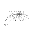
- the fragmentary cross-section of Fig. 2 shows components of the implanted HEP parameter sensor, the one between a dashed in the Fig. 2 indicated calotte 2 and the scalp 3 of a patient are arranged.
- This includes a wireless sensor transponder 4 with an antenna coil.
- the sensor transponder 4 is also referred to below as a transmitting unit.
- the transmitting unit 4 is connected via a line 5 and a rectification, not shown, with a capacitor 6 is in electrical contact.
- the representation after Fig. 2 is very schematic and not to scale.
- the sensor transponder 4 does not have its own energy source.
- the sensor transponder 4 additionally has an A / D converter (not shown). This serves to digitize the sensor measurement data to be relayed by the sensor transponder 4.
- a rotational symmetry axis 7 of the antenna coil of the transmitting unit 4 is in the Fig. 2 indicated by dashed lines.
- the axis 7 runs due to the arrangement of the transmitting unit 4 substantially normal to the outer wall of the cap 2 in the region of the support of the antenna coil of the transmitting unit 4 on this.
- the transmitting unit 4 is connected to a sensor element of the brain parameter sensor.
- the sensor element is designed, for example, as a catheter guided through the calotte 2 with a pressure measuring head.
- the transmitting unit 4 Associated with the transmitting unit 4 is an external transmitting / receiving unit 8 of the sensor system 1, which is also referred to below as a receiving unit or as a reader.
- the receiving unit 8 is arranged outside the patient's head.
- the receiving unit 8 has an antenna 9, which is wirelessly connected to the power supply and for data transmission with the transmitting unit 4 in signal connection.
- the antenna 9 is as part of a printed circuit board (PCB) on a thin board 10 with a thickness between 0.8 mm and 1.5 mm printed. Even an even thinner board is possible.
- the board 10 may be formed as a flexible, ie as a flexible board.
- the antenna 9 also has the shape of a coil whose rotational symmetry axis coincides with the axis 7.
- the coil turns of the units 4, 8 may be arranged in particular spirally.
- the board 10 is attached to an annular housing 11 with a diameter of a few cm.
- the rotational symmetry axis of the housing 11 coincides with the axis 7.
- the mounting location of the board 10 is on a side facing away from the scalp 3 side of the housing eleventh
- a flexible membrane 12 is fixed to the housing 11 on the scalp 3 side facing.
- the membrane 12 thus lies between the antenna 9 and the scalp 3.
- a layer 13 of a resilient, shape-changing material in particular of a flowable and highly viscous material, in particular arranged from a gel.
- the membrane 12 adapts to the shape of the patient's head at this point due to targeted displacement of the layer 13, so that a correct fit of the receiving unit 8 relative to Transmitter unit 4 is guaranteed.
- the receiving unit 8 is fixed to the inside of a hood 14, which is also part of the sensor system 1.
- a Velcro connection with a Velcro strip 15 which is glued on the hood 14 side facing the housing 11 and the board 10 of the receiving unit 8.
- the hood 14 is made of a stretchy and close to the patient's head gauze or cotton material.
- the hood 14 is adapted in section to the shape of the patient's head.
- the hood 14 may have a chin strap not shown in the drawing for fixation on the patient's head.
- the hood 14 may also have a in Fig. 2 dashed lines indicated outer hood 16 may be provided which receives forces from the outside and thus the then inner hood 14 secures against undesired slipping relative to the calotte 2.
- the antenna 9 of the receiving unit 8 is in signal communication with a data reading module 18.
- the data reading module 18 comprises a control unit for controlling the implanted HEP parameter sensor via the receiving unit 8, via which bidirectional data transmission is possible. Further, the data read module 18 has a high frequency source for generating a carrier frequency of 13.56 MHz. The data read module 18 also has a latch. The data reading module 18 is approximately the size of a pack of cigarettes and can be worn by the patient on the belt.
- the data reading module 18 is in signal connection with a data processing and display device 20.
- the latter has a display 21 and a plurality of control buttons 22 and connection sockets 23, in particular at least one USB interface.
- the data processing and display device 20 can be connected to an external voltage source.
- the data processing and display device 20 may have an internal energy source, for example in the form of a battery or a rechargeable accumulator.
- the data reading module 18, the receiving unit 8 and also the transmitting unit 4 are supplied with power wirelessly during a measuring process via this energy source.
- the signal connection between the antenna 9 and the data reading module 18 on the one hand and the data reading module 18 and the data processing and display device 20 on the other hand can be a USB interface or an RS232 interface, ie a digital interface.
- a brain parameter measurement procedure which is regularly repeated over a longer period of time, for example over several days, proceeds as follows:
- the data reading module 18 first sends an RF signal to the transmitting unit 4 via the receiving unit 8.
- the RF signal is rectified and charges the capacitor 6 for temporary power supply to the transmitting unit 4.
- RF signal is deactivated.
- the brain parameter sensor supplied via the capacitor 6, records the brain parameter measurement signal, for example a brain pressure value.
- the RF signal is reactivated and the transmitting unit. 4 sends with the RF signal as a carrier frequency digitized via the A / D converter measured value as a digitally modulated signal to the receiving unit 8.
- the receiving unit 8 takes place a transfer or decoding of the modulated RF signal into a digital, PC-compatible signal , Depending on the interface standard used in the sensor system 1, it may be, for example, a USB or an RS232 signal.
- This transferred measuring signal is transmitted to the data reading module 18 via the signal cable 17.
- the transmitted signal is then transmitted via the signal cable 19 to the data processing and display device 20 for further processing and presentation.
- the hood 14 may be formed as a network of a plurality of individual bands or hoses. Through these individual bands or hoses then a grid is specified.
- the receiving unit 8 can then have fastening means on the individual bands or hoses, which in particular allow the receiving unit 8 to be fastened at points of intersection of this grid.
- headbands from single bands or hoses are known in the context of EEG headgear.
- the receiving unit 8 and the data reading module 18 are designed as an integrated unit and attached to the hood 14.
- the data reading module can also be fastened by the receiving unit 8 separately on the inside of the hood 14, for example on a position opposite the receiving unit 8.
- the receiving unit 8 and the iesemodul 18 can then be connected to each other via a short signal cable.
- a corresponding integration of the receiving unit 8 is also possible with individual components of the data reading module 18, for example with the RF source or with the control unit of the data reading module 18. The remaining components are in turn via a signal connection with an external, so outside the hood 14 mounted module connected.
- the receiving unit 8 also has additional components of the data reading module 18, it is also possible for the receiving unit 8 to have its own energy supply, for example in the form of a button cell. In this case, it is also possible to dispense with a wired signal connection, and at the stalks of the signal cable 17, a wireless signal connection, for example a Bluetooth signal connection, can be used.
- a wireless signal connection for example a Bluetooth signal connection
- the data reading module 18 has its own power supply and instead of a wired signal connection to the data processing and representation device 20 (signal cable 19), there is a wireless signal connection, which can also be realized, for example, via a Bluetooth connection.
- the data processing and presentation device 20 need not be constantly in signal communication with the data reading module 18. It is sufficient if the data processing and presentation device 20, the recorded measurement data from the data reading module 18 after completion of the read, for example, multi-day measurement. Only then is a corresponding data connection required, so that the patient only has to wear the head cap 14 with the receiving unit 8 and the data reading module 18 during the measuring time.
- the location-flexible positioning of the receiving unit 8 via the Velcro connection with the Velcro strip 15 allows an exact alignment of the receiving unit 8 to the transmitting unit 4, so that the coil axes of these two units 4, 8 coincide. This ensures optimum signal transmission between the units 4 and 8.
- the receiving unit 8 is designed with an annular housing 11, in which a likewise annular antenna 9 is incorporated. This ring antenna is placed in this embodiment on the head of the patient.
- the remaining receiving unit so the other components that in the execution of the FIGS. 1 and 2 in particular on the printed circuit on the board 10 are connected to the loop antenna via a data cable.
- This remaining receiving unit can for example be worn on the belt or placed on a laboratory bench. This separation of the loop antenna from the other receiving unit reduces the size and weight of the aufdinden the head of the patient component.
- the housing of the ring antenna of this embodiment may have characteristic bulges and / or depressions and / or other recesses, which serve for manual positioning of the ring antenna to facilitate the positioning thereof.
- the housing of the ring antenna may have radially extending recesses on the top side facing away from the patient's head in the mounted position of the ring antenna. These radially extending recesses can serve as fastening aids for a Velcro strip for fixing the ring antenna to the hood 14.
Landscapes
- Health & Medical Sciences (AREA)
- Life Sciences & Earth Sciences (AREA)
- Engineering & Computer Science (AREA)
- General Health & Medical Sciences (AREA)
- Veterinary Medicine (AREA)
- Biophysics (AREA)
- Pathology (AREA)
- Physics & Mathematics (AREA)
- Biomedical Technology (AREA)
- Heart & Thoracic Surgery (AREA)
- Medical Informatics (AREA)
- Molecular Biology (AREA)
- Surgery (AREA)
- Animal Behavior & Ethology (AREA)
- Public Health (AREA)
- Neurology (AREA)
- Physiology (AREA)
- Computer Networks & Wireless Communication (AREA)
- Neurosurgery (AREA)
- Hematology (AREA)
- Psychology (AREA)
- Artificial Intelligence (AREA)
- Computer Vision & Pattern Recognition (AREA)
- Psychiatry (AREA)
- Signal Processing (AREA)
- Measuring And Recording Apparatus For Diagnosis (AREA)
- Measurement And Recording Of Electrical Phenomena And Electrical Characteristics Of The Living Body (AREA)
- Arrangements For Transmission Of Measured Signals (AREA)
Description
- Die Erfindung betrifft ein Sensorsystem zur Messung, Übertragung, Verarbeitung und Darstellung eines Hirnparameters nach dem Oberbegriff des Anspruchs 1.
- Ferner betrifft die Erfindung eine Kopfhaube für ein derartiges Sensorsystem.
- Ein Sensorsystem der eingangs genannten Art ist bekannt aus der
WO2004/023993 A1 . Weitere Sensorsysteme sind bekannt aus derEP 1 312 302 A2 , derDE 696 34 810 T2 , derDE 197 05 474 A1 , derDE 696 34 689 T2 , derUS 4,519,401 A , derUS 2003/0023146 A1 , derUS 5 873 840 , derUS 2005/0090756 A1 , derUS 4 676 255 und derUS 2005/0137652 A1 . - Aus der
DE 102 15 115 A1 ist eine EEG-Kappe mit Sensoren bekannt, die zur Ausbildung einer Messeinrichtung in einer Vorrichtung zur reaktiven automatischen nicht invasiven gesteuerten bzw. geregelten elektromagnetischen Prävention epileptischer Anfälle in vivo ein Sensorgitter bilden. - Hirnparametermessungen finden insbesondere mit dem Ziel statt, die Notwendigkeit für spätere Therapiemaßnahmen abzuklären. Ein Anwendungsbeispiel ist hierfür eine Hirndruck-Langzeitmessung zur Klärung der Frage, ob ein Hydrocephaluspatient ein Shuntventil benötigt und wie ein derartiges Ventil hinsichtlich seiner Dimensionierung ausgelegt werden muss. Hierfür ist eine Datenerfassung des Hirndruckverlaufes über einen längeren Zeitraum, beispielsweise über Nacht oder über mehrere Tage erforderlich, um aus der Dynamik des Hirndrucks (ICP, Intracranial Pressure) eine entsprechende Diagnose ableiten zu können.
- Der Einsatz der bisher bekannten Sensorsysteme zur Bearbeitung derartiger Fragestellungen ist für den Patienten sehr unbequem und beschwerlich.
- Es ist eine Aufgabe der vorliegenden Erfindung, ein Sensorsystem der eingangs genannten Art derart weiterzubilden, dass dessen Einsatz auch über einen längeren Messzeitraum für den Patienten komfortabel bleibt.
- Diese Aufgabe wird erfindungsgemäß gelöst durch ein Sensorsystem mit den im Anspruch 1 angegebenen Merkmalen.
- Erfindungsgemäß wurde erkannt, dass diejenigen Komponenten, die zum Empfangen der Messdaten vom implantierten Hirnparametersensor erforderlich sind, so leicht und bauklein gestaltet werden können, dass sie ohne weiteres an einer Kopfhaube befestigt werden können. Die Kopfhaube schützt die Empfangseinheit. Der Patient kann sich mit der Kopfhaube im Wesentlichen frei bewegen, muss also während der Messdauer nicht stationär untergebracht sein. Die Kopfhaube stellt eine exakte Relativposition der Empfangseinheit zur Sendeeinheit sicher.
- Eine Gitternetz-Kopfhaube hat sich beim Einsatz im Zusammenhang mit EEG-(Elektroenzephalographie-)Systemen bewährt. Eine entsprechende Gitternetz-Kopfhaube kommt auch, nach Ausrüstung mit einer entsprechenden Empfangseinheit, beim Sensorsystem zum Einsatz.
- Eine Antenne nach Anspruch 2 ist besonders leicht und bauklein und damit komfortabel zu tragen.
- Eine Klettverbindung nach Anspruch 3 erlaubt eine ortsflexible Relativpositionierung zur Justierung der Empfangseinheit relativ zur Sendeeinheit. Hierzu kann die Empfangseinheit gegenüber der Kopfhaube stufenlos verlagert werden, bis eine gewünschte Soll-Signalstärke bei der Übertragung zwischen der Sendeeinheit und der Empfangseinheit erreicht ist. Insbesondere ist es möglich, Symmetrieachsen der Sendeeinheit und der Empfangseinheit miteinander praktisch vollständig zur Überdeckung zu bringen, was eine sehr gute Qualität der Signalübertragung gewährleistet.
- Ein Gehäusering nach Anspruch 4 gewährleistet eine sichere Anlage der Empfangseinheit am Patientenkopf. Da die Sendeeinheit in der Regel zwischen der Kopfhaut und der Kalotte untergebracht ist, stellt die Sendeeinheit eine deutlich fühlbare Erhebung am Patientenkopf dar. Der Gehäusering ist bevorzugt so dimensioniert, dass er diese Erhebung zumindest abschnittsweise umschließt, was die Relativpositionierung der Sendeeinheit zur Empfangseinheit verbessert.
- In dem am Patientenkopf anlegbaren Gehäuse bzw. Gehäusering kann nur ein Teil der die Empfangseinheit aufbauenden Komponenten untergebracht sein. Bevorzugt ist lediglich die Antenne der Empfangseinheit im Gehäuse bzw. Gehäusering untergebracht, wohingegen die anderen Komponenten der Empfangseinheit beispielsweise über eine kabelgebundene oder auch über eine kabellose Signalverbindung mit der Antenne in Verbindung stehen. Die am Patientenkopf anlegbare Komponente kann dann leicht und kompakt ausgestaltet sein.
- Ausgestaltungen nach den Ansprüchen 5 und 6 verbessern die Anlage der Empfangseinheit an der Sendeeinheit und damit die Relativpositionierung dieser beiden Einheiten zueinander.
- Eine Integration nach Anspruch 7 vermeidet insbesondere, dass der Patient neben der Kopfhaube noch zusätzliche Komponenten beispielsweise am Gürtel tragen muss.
- Die Vorteile einer Kopfhaube nach Anspruch 8 entsprechen denen, die vorstehend unter Bezugnahme auf das erfindungsgemäße Sensorsystem bereits ausgeführt wurden.
- Ein Ausführungsbeispiel der Erfindung wird nachfolgend anhand der Zeichnung näher erläutert. In dieser zeigen:
- Fig. 1
- ein Sensorsystem zur Messung, Übertragung, Verarbeitung und Darstellung eines Hirnparameters;
- Fig. 2
- schematisch einen Schnitt durch eine auf einen Patientenkopf aufgesetzte Kopfhaube des Sensorsystems im Bereich einer an der Kopfhaube festgelegten Antenne.
- Ein in der
Fig. 1 insgesamt dargestelltes Sensorsystem 1 dient zur Messung, Übertragung, Verarbeitung und Darstellung eines Hirnparameters, insbesondere eines Hirndrucks. - Zum Sensorsystem 1 gehört ein nicht näher dargestellter, in einen Patientenkopf implantierbarer Hirnparametersensor. Der ausschnittsweise Querschnitt der
Fig. 2 zeigt Komponenten des implantierten Himparametersensors, die zwischen einer gestrichelt in derFig. 2 angedeuteten Kalotte 2 und der Kopfhaut 3 eines Patienten angeordnet sind. Hierzu gehört ein drahtloser Sensortransponder 4 mit einer Antennenspule. Der Sensortransponder 4 wird nachfolgend auch als Sendeeinheit bezeichnet. Die Sendeeinheit 4 steht über eine Leitung 5 sowie eine nicht dargestellte Gleichrichtung mit einem Kondensator 6 in elektrischem Kontakt steht. Die Darstellung nachFig. 2 ist äußerst schematisch und nicht maßstabsgerecht. - Der Sensortransponder 4 hat keine eigene Energiequelle. Der Sensortransponder 4 weist zusätzlich einen nicht näher dargestellten A/D-Wandler auf. Dieser dient zur Digitalisierung der vom Sensortransponder 4 weiterzugebenden Sensor-Messdaten.
- Eine Rotationssymmetrieachse 7 der Antennenspule der Sendeeinheit 4 ist in der
Fig. 2 gestrichelt angedeutet. Die Achse 7 verläuft bedingt durch die Anordnung der Sendeeinheit 4 im Wesentlichen normal zur Außenwand der Kalotte 2 im Bereich der Auflage der Antennenspule der Sendeeinheit 4 auf dieser. - Über eine nicht dargestellte Signalverbindung ist die Sendeeinheit 4 mit einem Sensorelement des Hirnparametersensors verbunden. Das Sensorelement ist beispielsweise als durch die Kalotte 2 hindurch geführter Katheter mit einem Druckmesskopf ausgeführt.
- Der Sendeeinheit 4 zugeordnet ist eine äußere Sende/Empfangseinheit 8 des Sensorsystems 1, die nachfolgend auch nur als Empfangseinheit oder als Reader bezeichnet wird. Die Empfangseinheit 8 ist außerhalb des Patientenkopfes angeordnet. Die Empfangseinheit 8 hat eine Antenne 9, die drahtlos zur Energieversorgung sowie zur Datenübermittlung mit der Sendeeinheit 4 in Signalverbindung steht. Die Antenne 9 ist als Teil einer gedruckten Schaltung (PCB, printed circuit board) auf einer dünnen Platine 10 mit einer Stärke zwischen 0,8 mm und 1,5 mm aufgedruckt. Auch eine noch dünnere Platine ist möglich. Zur Verbesserung der Anpassungsfähigkeit der Empfangseinheit 8 kann die Platine 10 als flexible, also als biegsame Platine ausgebildet sein. Die Antenne 9 hat ebenfalls die Form einer Spule, deren Rotationssymmetrieachse mit der Achse 7 zusammenfällt. Die Spulenwindungen der Einheiten 4, 8 können insbesondere spiralförmig angeordnet sein.
- Die Platine 10 ist an einem ringförmigen Gehäuse 11 mit einem Durchmesser von einigen cm befestigt. Auch die Rotationssymmetrieachse des Gehäuses 11 fällt mit der Achse 7 zusammen. Der Befestigungsort der Platine 10 ist auf einer von der Kopfhaut 3 abgewandten Seite des Gehäuses 11.
- Ferner ist am Gehäuse 11 an der der Kopfhaut 3 zugewandten Seite eine flexible Membran 12 festgelegt. Die Membran 12 liegt somit zwischen der Antenne 9 und der Kopfhaut 3.
- Zwischen der Antenne 9 und der Membran 12 ist eine Schicht 13 aus einem nachgiebigen, formveränderlichen Material, insbesondere aus einem fließfähigen und hochviskosem Material, insbesondere aus einem Gel angeordnet.
- Beim Auflegen der Empfangseinheit 8 über das Gehäuse 11 auf die Kopfhaut 3 im Bereich der Sendeeinheit 4 passt sich aufgrund einer gezielten Verdrängung der Schicht 13 die Membran 12 an die Form des Patientenkopfes an dieser Stelle an, so dass ein korrekter Sitz der Empfangseinheit 8 relativ zur Sendeeinheit 4 gewährleistet ist.
- Die Empfangseinheit 8 ist an der Innenseite einer Kopfhaube 14 festgelegt, die ebenfalls Teil des Sensorsystems 1 ist. Zur Befestigung der Empfangseinheit 8 an der Kopfhaube 14 dient eine Klettverbindung mit einem Klettband 15, das auf der der Kopfhaube 14 zugewandten Seite auf das Gehäuse 11 und die Platine 10 der Empfangseinheit 8 aufgeklebt ist. Über diese Klettverbindung lässt sich die Empfangseinheit 8 an einer beliebigen Stelle auf der Innenseite der Kopfhaube 14 anbringen, so dass eine gewünschte Relativpositionierung der Empfangseinheit 8 zur Sendeeinheit 4 möglich ist. Die Kopfhaube 14 ist aus einem dehnbaren und eng am Patientenkopf anliegenden Gaze oder Baumwollmaterial. Die Kopfhaube 14 ist im Schnitt an die Form des Patientenkopfes angepasst. Die Kopfhaube 14 kann zur Fixierung am Patientenkopf ein in der Zeichnung nicht dargestelltes Kinnband aufweisen. Zusätzlich zur Kopfhaube 14 kann auch noch eine in
Fig. 2 gestrichelt angedeutete äußere Überhaube 16 vorgesehen sein, die Kräfte von außen aufnimmt und somit die dann innere Kopfhaube 14 gegen ein unerwünschtes Verrutschen relativ zur Kalotte 2 sichert. - Über ein Signalkabel 17, welches abschnittsweise zwischen der Kopfhaut 3 und der Kopfhaube 14 verläuft, steht die Antenne 9 der Empfangseinheit 8 mit einem Datenlesemodul 18 in Signalverbindung. Das Datenlesemodul 18 umfasst eine Steuereinheit zur Steuerung des implantierten Himparametersensors über die Empfangseinheit 8, über die eine bidirektionale Datenübertragung möglich ist. Ferner hat das Datenlesemodul 18 eine Hochfrequenzquelle zur Erzeugung einer Trägerfrequenz von 13,56 MHz. Das Datenlesemodul 18 hat zudem einen Signalspeicher. Das Datenlesemodul 18 hat in etwa die Größe einer Zigarettenschachtel und kann vom Patienten am Gürtel getragen werden.
- Über ein weiteres Signalkabel 19 steht das Datenlesemoduls 18 mit einer Datenverarbeitungs- und -darstellungseinrichtung 20 in Signalverbindung. Letztere hat ein Display 21 sowie eine Mehrzahl von Bedienknöpfen 22 und Anschlussbuchsen 23, insbesondere mindestens eine USB-Schnittstelle. Die Datenverarbeitungs- und -darstellungseinrichtung 20 ist mit einer externen Spannungsquelle verbindbar. Alternativ oder zusätzlich kann die Datenverarbeitungs- und -darstellungseinrichtung 20 eine interne Energiequelle, beispielsweise in Form einer Batterie oder eines aufladbaren Akkumulators, aufweisen. Über diese Energiequelle werden das Datenlesemodul 18, die Empfangseinheit 8 und drahtlos während eines Messvorgangs auch die Sendeeinheit 4 versorgt.
- Bei der Signalverbindung zwischen der Antenne 9 und dem Datenlesemodul 18 einerseits und dem Datenlesemodul 18 und der Datenverarbeitungs- und -darstellungseinrichtung 20 andererseits kann es sich um eine USB-Schnittstelle oder auch um eine RS232-Schnittstelle, also um ein digitales Interface, handeln.
- Ein Hirnparameter-Messvorgang, der über einen längeren Zeitraum, beispielsweise im Verlauf mehrerer Tage, regelmäßig wiederholt wird, läuft folgendermaßen ab:
- Das Datenlesemodul 18 sendet über die Empfangseinheit 8 zunächst ein HF-Signal an die Sendeeinheit 4. Das HF-Signal wird gleichgerichtet und lädt den Kondensator 6 zur zeitweiligen Energieversorgung der Sendeeinheit 4 auf. Nach diesem Ladevorgang wird HF-Signal deaktiviert. Anschließend nimmt der Hirnparametersensor, versorgt über den Kondensator 6, das Hirnparameter-Messsignal, beispielsweise einen Hirndruckwert, auf. Anschließend wird das HF-Signal wieder aktiviert und die Sendeeinheit 4 sendet mit dem HF-Signal als Trägerfrequenz den über den A/D-Wandler digitalisierten Messwert als digital moduliertes Signal an die Empfangseinheit 8. In der Empfangseinheit 8 erfolgt eine Überführung bzw. Dekodierung des modulierten HF-Signals in ein digitales, PC-kompatibles Signal. Je nach dem Schnittstellen-Standard, der beim Sensorsystem 1 eingesetzt wird, kann es sich beispielsweise um ein USB- oder um ein RS232-Signal handeln. Dieses überführte Messsignal wird an das Datenlesemodul 18 über das Signalkabel 17 übertragen. Das übertragene Signal wird dann über das Signalkabel 19 an die Datenverarbeitungs- und -darstellungseinrichtung 20 zur weiteren Verarbeitung und Darstellung übermittelt.
- An Stelle einer Gaze- oder Baumwoll-Ausführung der Kopfhaube 14 und gegebenenfalls der Überhaube 16 kann die Kopfhaube 14 auch als Netz aus einer Mehrzahl von Einzelbändern oder -schläuchen ausgebildet sein. Durch diese Einzelbänder oder -schläuche wird dann ein Gitternetz vorgegeben. Die Empfangseinheit 8 kann dann Befestigungsmittel an den Einzelbändern oder -schläuchen aufweisen, die es insbesondere erlauben, die Empfangseinheit 8 an Kreuzungspunkten dieses Gitternetzes zu befestigen. Entsprechende Ausführungen von Kopfhauben aus Einzelbändern oder -schläuchen sind im Zusammenhang mit EEG-Kopfhauben bekannt.
- Bei einer weiteren Variante des Sensorsystems 1 sind die Empfangseinheit 8 und das Datenlesemodul 18 als integrierte Baueinheit ausgeführt und an der Kopfhaube 14 befestigt. Zur Gewichtsverteilung dieser integrierten Baueinheit kann das Datenlesemodul auch von der Empfangseinheit 8 separat innen an der Kopfhaube 14 befestigt sein, beispielsweise an einer der Empfangseinheit 8 gegenüberliegenden Position. Die Empfangseinheit 8 und das Dateniesemodul 18 können dann über ein kurzes Signalkabel miteinander verbunden sein.
- Eine entsprechende Integration der Empfangseinheit 8 ist auch mit Einzelkomponenten des Datenlesemoduls 18 möglich, beispielsweise mit der HF-Quelle oder mit der Steuereinheit des Datenlesemoduls 18. Die restlichen Komponenten sind dann wiederum über eine Signalverbindung mit einem externen, also außerhalb der Kopfhaube 14 angebrachten, Modul verbunden.
- Bei diesen integrierten Varianten, bei denen die Empfangseinheit 8 noch zusätzliche Komponenten des Datenlesemoduls 18 aufweist, ist es auch möglich, dass die Empfangseinheit 8 eine eigene Energieversorgung, beispielsweise in Form einer Knopfzelle aufweist. In diesem Fall kann auf eine kabelgebundene Signalverbindung auch verzichtet werden und an Stele des Signalkabels 17 kann eine drahtlose Signalverbindung, beispielsweise eine Bluetooth-Signalverbindung zum Einsatz kommen.
- Bei einer weiteren Variante des Sensorsystems 1 hat das Datenlesemodul 18 eine eigene Energieversorgung und an Stelle einer kabelgebundenen Signalverbindung mit der Datenverarbeitungs- und -darstellungseinrichtung 20 (Signalkabel 19) liegt eine drahtlose Signalverbindung vor, die beispielsweise ebenfalls über eine Bluetooth-Verbindung realisiert sein kann.
- Die Datenverarbeitungs- und -darstellungseinrichtung 20 muss nicht ständig mit dem Datenlesemodul 18 in Signalverbindung stehen. Es reicht aus, wenn die Datenverarbeitungs- und -darstellungseinrichtung 20 die aufgenommenen Messdaten aus dem Datenlesemodul 18 nach Abschluss der beispielsweise mehrtätigen Messzeit ausliest. Erst dann ist eine entsprechende Datenverbindung erforderlich, so dass der Patient während der Messzeit nur die Kopfhaube 14 mit der Empfangseinheit 8 und das Datenlesemodul 18 tragen muss.
- Die ortsflexible Positionierung der Empfangseinheit 8 über die Klettverbindung mit dem Klettband 15 ermöglicht eine exakte Ausrichtung der Empfangseinheit 8 zur Sendeeinheit 4, so dass die Spulenachsen dieser beiden Einheiten 4, 8 zusammenfallen. Dies gewährleistet eine optimale Signalübertragung zwischen den Einheiten 4 und 8.
- Bei einer nicht näher dargestellten Ausführung ist die Empfangseinheit 8 mit einem ringförmigen Gehäuse 11 ausgeführt, in das eine ebenfalls ringförmige Antenne 9 eingearbeitet ist. Diese Ringantenne wird bei dieser Ausführungsform am Kopf des Patienten aufgesetzt. Die restliche Empfangseinheit, also die weiteren Komponenten, die bei der Ausführung nach den
Figuren 1 und2 insbesondere auf der gedruckten Schaltung auf der Platine 10 ausgeführt sind, sind mit der Ringantenne über ein Datenkabel verbunden. Diese restliche Empfangseinheit kann beispielsweise am Gürtel getragen oder auf einem Labortisch aufgestellt werden. Diese Trennung der Ringantenne von der sonstigen Empfangseinheit verringert die Baugröße und das Gewicht der am Kopf des Patienten aufzusetzenden Komponente. - Das Gehäuse der Ringantenne dieser nicht weiter dargestellten Ausführung kann charakteristische Ausbuchtungen und/oder Mulden und/oder sonstige Vertiefungen aufweisen, die beim manuellen Aufsetzen der Ringantenne zur Erleichterung der Positionierung von dieser dienen. Es können beispielsweise drei Ausbuchtungen und/oder Mulden und/öder Vertiefungen vorliegen, die in etwa gleich verteilt am Außenumfang der Ringantenne angeordnet sind.
- Das Gehäuse der Ringantenne kann radial verlaufende Vertiefungen an der vom Patientenkopf in der aufgesetzten Stellung abgewandten Oberseite der Ringantenne aufweisen. Diese radial verlaufenden Vertiefungen können als Befestigungshilfen für ein Klettband zur Fixierung der Ringantenne an der Kopfhaube 14 dienen.
Claims (8)
- Sensorsystem (1) zur Messung, Übertragung, Verarbeitung und Darstellung eines Hirnparameters- mit mindestens einem implantierbaren Hirnparametersensor mit einer drahtlosen Sendeeinheit (4) zur Messung des Himparameters,- mit mindestens einer Empfangseinheit (8) mit einer Antenne (9), die mit der Sendeeinheit (4) in drahtloser Signalverbindung steht,- mit mindestens einem Datenlesemodul (18), welches mit der Antenne (9) über eine Signalverbindung (17) in Signalverbindung steht,- mit mindestens einer Datenverarbeitungs- und -darstellungseinrichtung (20), welche mit dem Datenlesemodul (18) in Signalverbindung (19) steht,
gekennzeichnet durch eine Kopfhaube (14), an der die Empfangseinheit (8) zur Vorgabe einer Relativpositionierung relativ zur Sendeeinheit (4) festgelegt ist, wobei die Kopfhaube (14) eine Mehrzahl von Einzelbändern oder -schläuchen aufweist, die ein Gitternetz vorgeben, wobei die Empfangseinheit (8) an Kreuzungspunkten des Gitternetzes festlegbar ist. - Sensorsystem (1) nach Anspruch 1, dadurch gekennzeichnet, dass die Antenne (9) Teil einer gedruckten Schaltung ist.
- Sensorsystem (1) nach Anspruch 1 oder 2, dadurch gekennzeichnet, dass die Empfangseinheit (8) an der Kopfhaube (14) über eine Klettverbindung (15) festgelegt ist.
- Sensorsystem (1) nach einem der Ansprüche 1 bis 3, dadurch gekennzeichnet, dass die Empfangseinheit (8) über einen Gehäusering (11) an einem Patientenkopf anlegbar ist.
- Sensorsystem (1) nach einem der Ansprüche 1 bis 4, gekennzeichnet durch eine flexible Membran (12), über die die Empfangseinheit (8) an dem Patientenkopf anlegbar ist.
- Sensorsystem (1) nach Anspruch 5, dadurch gekennzeichnet, dass zwischen der flexiblen Membran (12) und der Antenne (9) eine formveränderliche Schicht (13), insbesondere eine Gelschicht, angeordnet ist.
- Sensorsystem (1) nach einem der Ansprüche 1 bis 6, dadurch gekennzeichnet, dass das Datenlesemodul (18) und die Empfangseinheit (8) als integrierte Baueinheit ausgeführt und an der Kopfhaube (14) festlegbar sind.
- Kopfhaube (14) mit einer Empfangseinheit (8) zum Einsatz in einem Sensorsystem (1) nach einem der Ansprüche 1 bis 7.
Priority Applications (1)
| Application Number | Priority Date | Filing Date | Title |
|---|---|---|---|
| EP13150166.0A EP2578145A1 (de) | 2007-09-28 | 2008-09-11 | Verfahren zur Übertragung von Sensordaten eines implantierbaren Hirnparametersensors auf ein externes Datenlesemodul |
Applications Claiming Priority (2)
| Application Number | Priority Date | Filing Date | Title |
|---|---|---|---|
| DE102007046694A DE102007046694A1 (de) | 2007-09-28 | 2007-09-28 | Sensorsystem zur Messung, Übertragung, Verarbeitung und Darstellung eines Hirnparameters |
| PCT/EP2008/007442 WO2009043431A1 (de) | 2007-09-28 | 2008-09-11 | Sensorsystem zur messung, übertragung verarbeitung und darstellung eines hirnparameters |
Related Child Applications (1)
| Application Number | Title | Priority Date | Filing Date |
|---|---|---|---|
| EP13150166.0A Division-Into EP2578145A1 (de) | 2007-09-28 | 2008-09-11 | Verfahren zur Übertragung von Sensordaten eines implantierbaren Hirnparametersensors auf ein externes Datenlesemodul |
Publications (2)
| Publication Number | Publication Date |
|---|---|
| EP2190349A1 EP2190349A1 (de) | 2010-06-02 |
| EP2190349B1 true EP2190349B1 (de) | 2015-11-11 |
Family
ID=40227700
Family Applications (2)
| Application Number | Title | Priority Date | Filing Date |
|---|---|---|---|
| EP13150166.0A Withdrawn EP2578145A1 (de) | 2007-09-28 | 2008-09-11 | Verfahren zur Übertragung von Sensordaten eines implantierbaren Hirnparametersensors auf ein externes Datenlesemodul |
| EP08802003.7A Not-in-force EP2190349B1 (de) | 2007-09-28 | 2008-09-11 | Sensorsystem zur messung, übertragung verarbeitung und darstellung eines hirnparameters |
Family Applications Before (1)
| Application Number | Title | Priority Date | Filing Date |
|---|---|---|---|
| EP13150166.0A Withdrawn EP2578145A1 (de) | 2007-09-28 | 2008-09-11 | Verfahren zur Übertragung von Sensordaten eines implantierbaren Hirnparametersensors auf ein externes Datenlesemodul |
Country Status (8)
| Country | Link |
|---|---|
| US (2) | US8337413B2 (de) |
| EP (2) | EP2578145A1 (de) |
| JP (1) | JP5789376B2 (de) |
| BR (1) | BRPI0815792B8 (de) |
| DE (1) | DE102007046694A1 (de) |
| DK (1) | DK2190349T3 (de) |
| ES (1) | ES2554337T3 (de) |
| WO (1) | WO2009043431A1 (de) |
Families Citing this family (17)
| Publication number | Priority date | Publication date | Assignee | Title |
|---|---|---|---|---|
| DE102007046694A1 (de) * | 2007-09-28 | 2009-04-09 | Raumedic Ag | Sensorsystem zur Messung, Übertragung, Verarbeitung und Darstellung eines Hirnparameters |
| US9901268B2 (en) | 2011-04-13 | 2018-02-27 | Branchpoint Technologies, Inc. | Sensor, circuitry, and method for wireless intracranial pressure monitoring |
| DE102011080192A1 (de) * | 2011-08-01 | 2013-02-07 | Raumedic Ag | Verfahren und Vorrichtung zur Übertragung von Sensordaten eines implantierbaren Sensors auf ein externes datenverarbeitendes Gerät |
| WO2013077887A1 (en) * | 2011-11-21 | 2013-05-30 | Medtronic, Inc. | Medical device communications system with communication controller using interface device |
| JP2014112819A (ja) * | 2012-10-30 | 2014-06-19 | Yokogawa Electric Corp | 無線機器、入出力ユニット、無線ユニット、及び無線機器の設定方法 |
| US9636017B2 (en) | 2013-03-13 | 2017-05-02 | DePuy Synthes Products, Inc. | Telemetric docking station |
| JP5898642B2 (ja) | 2013-05-20 | 2016-04-06 | 横河電機株式会社 | 無線機器 |
| US9901269B2 (en) | 2014-04-17 | 2018-02-27 | Branchpoint Technologies, Inc. | Wireless intracranial monitoring system |
| US9848789B2 (en) | 2014-04-17 | 2017-12-26 | Branchpoint Technologies, Inc. | Wireless intracranial monitoring system |
| DE202016005183U1 (de) | 2016-08-24 | 2017-11-27 | Raumedic Ag | Übertragungsvorrichtung zur Übertragung von Hirnparameter-Sensordaten |
| CN108095715A (zh) * | 2017-12-19 | 2018-06-01 | 苏州弘浩医疗科技有限公司 | 一种植入式无线无源颅内压力监测系统 |
| CN110013241A (zh) * | 2019-04-26 | 2019-07-16 | 侯立军 | 颅内压多探头监测系统 |
| AU2020256469B2 (en) | 2019-10-24 | 2026-03-05 | Longeviti Neuro Solutions, Inc | Cerebral spinal fluid shunt plug |
| GB2593153B (en) | 2020-03-09 | 2024-02-14 | Imperial College Innovations Ltd | Pressure sensor |
| EP4203778A4 (de) * | 2020-08-25 | 2024-12-25 | Canary Medical Switzerland AG | Okklusionsvorrichtung mit messfunktionalität |
| CN114098752B (zh) * | 2021-11-09 | 2024-10-25 | 上海掌门科技有限公司 | 一种用于呈现心电数据的方法、设备、介质及程序产品 |
| CN117179727B (zh) * | 2023-10-17 | 2025-02-11 | 中国人民解放军陆军军医大学第一附属医院 | 颅内压智能监测系统 |
Citations (3)
| Publication number | Priority date | Publication date | Assignee | Title |
|---|---|---|---|---|
| US3998213A (en) * | 1975-04-08 | 1976-12-21 | Bio-Volt Corporation | Self-adjustable holder for automatically positioning electroencephalographic electrodes |
| US20040054271A1 (en) * | 2001-04-02 | 2004-03-18 | Atsushi Maki | Biophotometer |
| EP1922997A1 (de) * | 2005-08-29 | 2008-05-21 | Hitachi Medical Corporation | Sondenhaltervorrichtung einer optischen messvorrichtung im lebenden körper |
Family Cites Families (39)
| Publication number | Priority date | Publication date | Assignee | Title |
|---|---|---|---|---|
| US5009A (en) * | 1847-03-13 | Ratchet-wrench | ||
| US5013A (en) * | 1847-03-13 | Improvement in apparatus for the manufacture of malleable iron | ||
| US4062354A (en) * | 1975-07-01 | 1977-12-13 | Taylor H Lyndon | Intracranial pressure transducer system |
| US4519401A (en) | 1983-09-20 | 1985-05-28 | Case Western Reserve University | Pressure telemetry implant |
| US4676255A (en) * | 1985-07-03 | 1987-06-30 | Cosman Eric R | Telemetric in-vivo calibration method and apparatus using a negative pressure applicator |
| US5591217A (en) * | 1995-01-04 | 1997-01-07 | Plexus, Inc. | Implantable stimulator with replenishable, high value capacitive power source and method therefor |
| US5752976A (en) * | 1995-06-23 | 1998-05-19 | Medtronic, Inc. | World wide patient location and data telemetry system for implantable medical devices |
| DE19705474A1 (de) | 1996-09-20 | 1998-08-27 | Sican F & E Gmbh Sibet | Implantierbare Meßeinheit zur intrakorporalen Messung von Patientendaten, insbesondere von Hirndrücken, für den mobilen Einsatz unter Alltagsbedingungen |
| US6471087B1 (en) | 1997-07-31 | 2002-10-29 | Larry Shusterman | Remote patient monitoring system with garment and automated medication dispenser |
| US5873840A (en) * | 1997-08-21 | 1999-02-23 | Neff; Samuel R. | Intracranial pressure monitoring system |
| US6354299B1 (en) * | 1997-10-27 | 2002-03-12 | Neuropace, Inc. | Implantable device for patient communication |
| US6016449A (en) * | 1997-10-27 | 2000-01-18 | Neuropace, Inc. | System for treatment of neurological disorders |
| ES2234235T3 (es) * | 1998-01-12 | 2005-06-16 | Ronald P. Lesser | Tecnica para usar flujo termico en el cerebro para tratar trastornos cerebrales. |
| US6708051B1 (en) * | 1998-11-10 | 2004-03-16 | Compumedics Limited | FMRI compatible electrode and electrode placement techniques |
| US6468219B1 (en) * | 2000-04-24 | 2002-10-22 | Philip Chidi Njemanze | Implantable telemetric transcranial doppler device |
| EP1349492A2 (de) * | 2001-01-04 | 2003-10-08 | Medtronic, Inc. | Implantierbare medizinische vorrichtung mit einem sensor |
| DE10156469B4 (de) | 2001-11-16 | 2004-05-13 | Cranium Telemetrics Gmbh | Vorrichtung zur intrakorporalen Messung des Hirndruckes |
| DE10215115A1 (de) * | 2002-04-05 | 2003-10-16 | Oliver Holzner | Verfahren und Vorrichtung zur Prävention epileptischer Anfälle |
| NO20023795D0 (no) * | 2002-07-02 | 2002-08-09 | Medinnova As | System for utlesning av trykk |
| DE10239743A1 (de) * | 2002-08-29 | 2004-03-25 | Rehau Ag + Co. | Vorrichtung zur Messung von Parametern im Hirn |
| US8024049B1 (en) * | 2003-10-20 | 2011-09-20 | University Of Central Florida Research Foundation, Inc. | Spatial-temporal deep brain stimulation methods and systems |
| US7187968B2 (en) * | 2003-10-23 | 2007-03-06 | Duke University | Apparatus for acquiring and transmitting neural signals and related methods |
| US20050107716A1 (en) * | 2003-11-14 | 2005-05-19 | Media Lab Europe | Methods and apparatus for positioning and retrieving information from a plurality of brain activity sensors |
| WO2005119838A2 (en) * | 2003-12-12 | 2005-12-15 | Hans Gregory Schantz | Nano-antenna apparatus and method |
| US20050137652A1 (en) * | 2003-12-19 | 2005-06-23 | The Board of Regents of the University of Texas at Dallas | System and method for interfacing cellular matter with a machine |
| US7647097B2 (en) * | 2003-12-29 | 2010-01-12 | Braingate Co., Llc | Transcutaneous implant |
| US7435229B2 (en) * | 2004-02-25 | 2008-10-14 | Wolf Erich W | System for transcutaneous monitoring of intracranial pressure (ICP) using near infrared (NIR) telemetry |
| US8057401B2 (en) * | 2005-02-24 | 2011-11-15 | Erich Wolf | System for transcutaneous monitoring of intracranial pressure |
| US20060020224A1 (en) * | 2004-07-20 | 2006-01-26 | Geiger Mark A | Intracranial pressure monitoring system |
| US20060020239A1 (en) * | 2004-07-20 | 2006-01-26 | Geiger Mark A | Cerebral spinal fluid flow sensing device |
| US7191013B1 (en) * | 2004-11-08 | 2007-03-13 | The United States Of America As Represented By The Administrator Of The National Aeronautics And Space Administration | Hand held device for wireless powering and interrogation of biomems sensors and actuators |
| DE102005008454B4 (de) * | 2005-02-24 | 2014-11-13 | Raumedic Ag | Anordnung mit Vorrichtung zur Messung von Hirnparametern |
| DE102005008627A1 (de) * | 2005-02-25 | 2006-08-31 | Raumedic Ag | Sensorsystem zur Messung, Übertragung, Verarbeitung und Darstellung von physiologischen Parametern |
| DE102005020569B4 (de) * | 2005-04-30 | 2010-08-05 | Aesculap Ag | Implantierbare Vorrichtung zur Erfassung von intrakorporalen Drücken |
| DE102006043058A1 (de) * | 2006-09-14 | 2008-03-27 | Raumedic Ag | Zustandssensor für Pflanzen sowie Bewässerungsanlage mit einem derartigen Zustandssensor |
| DE202007002592U1 (de) * | 2007-02-22 | 2007-04-19 | Aesculap Ag & Co. Kg | Messeinrichtung für physiologische Parameter |
| US8351982B2 (en) * | 2007-05-23 | 2013-01-08 | Broadcom Corporation | Fully integrated RF transceiver integrated circuit |
| DE102007046694A1 (de) * | 2007-09-28 | 2009-04-09 | Raumedic Ag | Sensorsystem zur Messung, Übertragung, Verarbeitung und Darstellung eines Hirnparameters |
| US20090112278A1 (en) * | 2007-10-30 | 2009-04-30 | Neuropace, Inc. | Systems, Methods and Devices for a Skull/Brain Interface |
-
2007
- 2007-09-28 DE DE102007046694A patent/DE102007046694A1/de not_active Withdrawn
-
2008
- 2008-09-11 DK DK08802003.7T patent/DK2190349T3/en active
- 2008-09-11 EP EP13150166.0A patent/EP2578145A1/de not_active Withdrawn
- 2008-09-11 ES ES08802003.7T patent/ES2554337T3/es active Active
- 2008-09-11 WO PCT/EP2008/007442 patent/WO2009043431A1/de not_active Ceased
- 2008-09-11 EP EP08802003.7A patent/EP2190349B1/de not_active Not-in-force
- 2008-09-11 JP JP2010526182A patent/JP5789376B2/ja not_active Expired - Fee Related
- 2008-09-11 BR BRPI0815792A patent/BRPI0815792B8/pt not_active IP Right Cessation
- 2008-09-11 US US12/680,721 patent/US8337413B2/en not_active Expired - Fee Related
-
2012
- 2012-12-21 US US13/724,937 patent/US20130123660A1/en not_active Abandoned
Patent Citations (3)
| Publication number | Priority date | Publication date | Assignee | Title |
|---|---|---|---|---|
| US3998213A (en) * | 1975-04-08 | 1976-12-21 | Bio-Volt Corporation | Self-adjustable holder for automatically positioning electroencephalographic electrodes |
| US20040054271A1 (en) * | 2001-04-02 | 2004-03-18 | Atsushi Maki | Biophotometer |
| EP1922997A1 (de) * | 2005-08-29 | 2008-05-21 | Hitachi Medical Corporation | Sondenhaltervorrichtung einer optischen messvorrichtung im lebenden körper |
Also Published As
| Publication number | Publication date |
|---|---|
| ES2554337T3 (es) | 2015-12-18 |
| JP2010540047A (ja) | 2010-12-24 |
| EP2578145A1 (de) | 2013-04-10 |
| US8337413B2 (en) | 2012-12-25 |
| BRPI0815792B1 (pt) | 2020-01-21 |
| DE102007046694A1 (de) | 2009-04-09 |
| BRPI0815792A2 (pt) | 2015-02-24 |
| US20100217108A1 (en) | 2010-08-26 |
| US20130123660A1 (en) | 2013-05-16 |
| BRPI0815792B8 (pt) | 2021-06-22 |
| JP5789376B2 (ja) | 2015-10-07 |
| DK2190349T3 (en) | 2016-02-15 |
| EP2190349A1 (de) | 2010-06-02 |
| WO2009043431A1 (de) | 2009-04-09 |
Similar Documents
| Publication | Publication Date | Title |
|---|---|---|
| EP2190349A1 (de) | Sensorsystem zur messung, übertragung verarbeitung und darstellung eines hirnparameters | |
| EP2537463B1 (de) | Medizinisches Sensorsystem | |
| DE10353943B4 (de) | Anordnung zur drahtlosen Energieübertragung an eine implantierte Einrichtung | |
| EP2089086B1 (de) | Atemschlauch-Anschlussvorrichtung | |
| EP2251660B1 (de) | Doppeltemperatursensor | |
| WO2007090543A1 (de) | Fixationssystem für knochen mit einem sensor- und telemetriesystem | |
| EP2244628B1 (de) | Patientendaten-sensorvorrichtung | |
| EP3634205B1 (de) | Vorrichtung zur sensorischen erfassung wenigstens eines menschlichen vitalparameters | |
| EP2862504A3 (de) | Telemetrievorrichtung zur Gesundheits- und Umgebungsüberwachung | |
| EP3064159A1 (de) | Bauteil und verfahren zum zusammenbau einer implantatanordnung | |
| EP3481330A1 (de) | Sensor und system zur überwachung der tragedauer von kieferorthopädischen gummizügen | |
| DE202016100667U1 (de) | EEG-Elektrode | |
| WO2010034546A1 (de) | Sensormodul zur erfassung von physiologischen daten | |
| EP2928368A2 (de) | Notrufsender | |
| DE102011080192A1 (de) | Verfahren und Vorrichtung zur Übertragung von Sensordaten eines implantierbaren Sensors auf ein externes datenverarbeitendes Gerät | |
| DE102005038147A1 (de) | Kombinationssensor für die Erfassung physiologischer Messgrößen auf der Haut eines Patienten | |
| EP0821542A2 (de) | Ganz im Gehörgang zu tragendes Hörgerät, das durch Giessen eines Körpers individualisiert wird | |
| DE102004016191A1 (de) | Rückhaltesystem mit Rückhaltegurt | |
| EP1559335A2 (de) | Bekleidungsstück | |
| EP3062687B1 (de) | Elastischer sensor zur messung von vitalparametern im gehörgang | |
| DE10006598A1 (de) | Einrichtung zur Früherkennung von kritischen Gesundheitszuständen, insbesondere bei Risikopatienten | |
| AT501058A1 (de) | Einrichtung für das abdecken einer wunde | |
| EP0837648A1 (de) | Einrichtung zur erfassung des krümmungszustandes von bereichen des menschlichen körpers | |
| DE102021107554B3 (de) | Wiederverwendbarer Kommunikationsadapter für Gesichtsmasken, System aus Kommunikationsadapter und Gesichtsmaske sowie Verfahren zum Bereitstellen eines solchen Systems | |
| WO2009003209A2 (de) | Modulare wundabdeckung |
Legal Events
| Date | Code | Title | Description |
|---|---|---|---|
| PUAI | Public reference made under article 153(3) epc to a published international application that has entered the european phase |
Free format text: ORIGINAL CODE: 0009012 |
|
| 17P | Request for examination filed |
Effective date: 20100122 |
|
| AK | Designated contracting states |
Kind code of ref document: A1 Designated state(s): AT BE BG CH CY CZ DE DK EE ES FI FR GB GR HR HU IE IS IT LI LT LU LV MC MT NL NO PL PT RO SE SI SK TR |
|
| AX | Request for extension of the european patent |
Extension state: AL BA MK RS |
|
| RIN1 | Information on inventor provided before grant (corrected) |
Inventor name: TAUBER, KARSTEN Inventor name: VON FALKENHAUSEN, CHRISTIAN Inventor name: KUNZE, GERD Inventor name: GOEHLER, KARL-HEINZ |
|
| DAX | Request for extension of the european patent (deleted) | ||
| 17Q | First examination report despatched |
Effective date: 20130220 |
|
| RIN1 | Information on inventor provided before grant (corrected) |
Inventor name: GOEHLER, KARL-HEINZ Inventor name: KUNZE, GERD Inventor name: VON FALKENHAUSEN, CHRISTIAN Inventor name: TAUBER, KARSTEN |
|
| GRAP | Despatch of communication of intention to grant a patent |
Free format text: ORIGINAL CODE: EPIDOSNIGR1 |
|
| INTG | Intention to grant announced |
Effective date: 20150522 |
|
| GRAS | Grant fee paid |
Free format text: ORIGINAL CODE: EPIDOSNIGR3 |
|
| GRAA | (expected) grant |
Free format text: ORIGINAL CODE: 0009210 |
|
| AK | Designated contracting states |
Kind code of ref document: B1 Designated state(s): AT BE BG CH CY CZ DE DK EE ES FI FR GB GR HR HU IE IS IT LI LT LU LV MC MT NL NO PL PT RO SE SI SK TR |
|
| REG | Reference to a national code |
Ref country code: GB Ref legal event code: FG4D Free format text: NOT ENGLISH |
|
| REG | Reference to a national code |
Ref country code: CH Ref legal event code: EP |
|
| REG | Reference to a national code |
Ref country code: IE Ref legal event code: FG4D Free format text: LANGUAGE OF EP DOCUMENT: GERMAN |
|
| REG | Reference to a national code |
Ref country code: AT Ref legal event code: REF Ref document number: 760012 Country of ref document: AT Kind code of ref document: T Effective date: 20151215 |
|
| REG | Reference to a national code |
Ref country code: ES Ref legal event code: FG2A Ref document number: 2554337 Country of ref document: ES Kind code of ref document: T3 Effective date: 20151218 |
|
| REG | Reference to a national code |
Ref country code: DE Ref legal event code: R096 Ref document number: 502008013566 Country of ref document: DE |
|
| REG | Reference to a national code |
Ref country code: NL Ref legal event code: FP |
|
| REG | Reference to a national code |
Ref country code: SE Ref legal event code: TRGR |
|
| REG | Reference to a national code |
Ref country code: DK Ref legal event code: T3 Effective date: 20160209 |
|
| REG | Reference to a national code |
Ref country code: LT Ref legal event code: MG4D |
|
| REG | Reference to a national code |
Ref country code: NO Ref legal event code: T2 Effective date: 20151111 |
|
| PG25 | Lapsed in a contracting state [announced via postgrant information from national office to epo] |
Ref country code: HR Free format text: LAPSE BECAUSE OF FAILURE TO SUBMIT A TRANSLATION OF THE DESCRIPTION OR TO PAY THE FEE WITHIN THE PRESCRIBED TIME-LIMIT Effective date: 20151111 Ref country code: LT Free format text: LAPSE BECAUSE OF FAILURE TO SUBMIT A TRANSLATION OF THE DESCRIPTION OR TO PAY THE FEE WITHIN THE PRESCRIBED TIME-LIMIT Effective date: 20151111 Ref country code: IS Free format text: LAPSE BECAUSE OF FAILURE TO SUBMIT A TRANSLATION OF THE DESCRIPTION OR TO PAY THE FEE WITHIN THE PRESCRIBED TIME-LIMIT Effective date: 20160311 |
|
| PG25 | Lapsed in a contracting state [announced via postgrant information from national office to epo] |
Ref country code: LV Free format text: LAPSE BECAUSE OF FAILURE TO SUBMIT A TRANSLATION OF THE DESCRIPTION OR TO PAY THE FEE WITHIN THE PRESCRIBED TIME-LIMIT Effective date: 20151111 Ref country code: PT Free format text: LAPSE BECAUSE OF FAILURE TO SUBMIT A TRANSLATION OF THE DESCRIPTION OR TO PAY THE FEE WITHIN THE PRESCRIBED TIME-LIMIT Effective date: 20160311 Ref country code: PL Free format text: LAPSE BECAUSE OF FAILURE TO SUBMIT A TRANSLATION OF THE DESCRIPTION OR TO PAY THE FEE WITHIN THE PRESCRIBED TIME-LIMIT Effective date: 20151111 Ref country code: GR Free format text: LAPSE BECAUSE OF FAILURE TO SUBMIT A TRANSLATION OF THE DESCRIPTION OR TO PAY THE FEE WITHIN THE PRESCRIBED TIME-LIMIT Effective date: 20160212 |
|
| REG | Reference to a national code |
Ref country code: DE Ref legal event code: R097 Ref document number: 502008013566 Country of ref document: DE |
|
| PG25 | Lapsed in a contracting state [announced via postgrant information from national office to epo] |
Ref country code: RO Free format text: LAPSE BECAUSE OF FAILURE TO SUBMIT A TRANSLATION OF THE DESCRIPTION OR TO PAY THE FEE WITHIN THE PRESCRIBED TIME-LIMIT Effective date: 20151111 Ref country code: EE Free format text: LAPSE BECAUSE OF FAILURE TO SUBMIT A TRANSLATION OF THE DESCRIPTION OR TO PAY THE FEE WITHIN THE PRESCRIBED TIME-LIMIT Effective date: 20151111 Ref country code: SK Free format text: LAPSE BECAUSE OF FAILURE TO SUBMIT A TRANSLATION OF THE DESCRIPTION OR TO PAY THE FEE WITHIN THE PRESCRIBED TIME-LIMIT Effective date: 20151111 |
|
| PLBE | No opposition filed within time limit |
Free format text: ORIGINAL CODE: 0009261 |
|
| STAA | Information on the status of an ep patent application or granted ep patent |
Free format text: STATUS: NO OPPOSITION FILED WITHIN TIME LIMIT |
|
| REG | Reference to a national code |
Ref country code: FR Ref legal event code: PLFP Year of fee payment: 9 |
|
| 26N | No opposition filed |
Effective date: 20160812 |
|
| PGFP | Annual fee paid to national office [announced via postgrant information from national office to epo] |
Ref country code: CH Payment date: 20160810 Year of fee payment: 9 Ref country code: NL Payment date: 20160922 Year of fee payment: 9 |
|
| PG25 | Lapsed in a contracting state [announced via postgrant information from national office to epo] |
Ref country code: SI Free format text: LAPSE BECAUSE OF FAILURE TO SUBMIT A TRANSLATION OF THE DESCRIPTION OR TO PAY THE FEE WITHIN THE PRESCRIBED TIME-LIMIT Effective date: 20151111 |
|
| PGFP | Annual fee paid to national office [announced via postgrant information from national office to epo] |
Ref country code: AT Payment date: 20160812 Year of fee payment: 9 Ref country code: CZ Payment date: 20160830 Year of fee payment: 9 |
|
| PG25 | Lapsed in a contracting state [announced via postgrant information from national office to epo] |
Ref country code: BE Free format text: LAPSE BECAUSE OF NON-PAYMENT OF DUE FEES Effective date: 20160930 |
|
| PG25 | Lapsed in a contracting state [announced via postgrant information from national office to epo] |
Ref country code: MC Free format text: LAPSE BECAUSE OF FAILURE TO SUBMIT A TRANSLATION OF THE DESCRIPTION OR TO PAY THE FEE WITHIN THE PRESCRIBED TIME-LIMIT Effective date: 20151111 |
|
| REG | Reference to a national code |
Ref country code: IE Ref legal event code: MM4A |
|
| PG25 | Lapsed in a contracting state [announced via postgrant information from national office to epo] |
Ref country code: IE Free format text: LAPSE BECAUSE OF NON-PAYMENT OF DUE FEES Effective date: 20160911 |
|
| PG25 | Lapsed in a contracting state [announced via postgrant information from national office to epo] |
Ref country code: LU Free format text: LAPSE BECAUSE OF NON-PAYMENT OF DUE FEES Effective date: 20160911 |
|
| REG | Reference to a national code |
Ref country code: FR Ref legal event code: PLFP Year of fee payment: 10 |
|
| REG | Reference to a national code |
Ref country code: BE Ref legal event code: MM Effective date: 20160930 |
|
| PG25 | Lapsed in a contracting state [announced via postgrant information from national office to epo] |
Ref country code: CZ Free format text: LAPSE BECAUSE OF NON-PAYMENT OF DUE FEES Effective date: 20170911 |
|
| REG | Reference to a national code |
Ref country code: CH Ref legal event code: PL |
|
| REG | Reference to a national code |
Ref country code: NL Ref legal event code: MM Effective date: 20171001 |
|
| REG | Reference to a national code |
Ref country code: AT Ref legal event code: MM01 Ref document number: 760012 Country of ref document: AT Kind code of ref document: T Effective date: 20170911 |
|
| PG25 | Lapsed in a contracting state [announced via postgrant information from national office to epo] |
Ref country code: HU Free format text: LAPSE BECAUSE OF FAILURE TO SUBMIT A TRANSLATION OF THE DESCRIPTION OR TO PAY THE FEE WITHIN THE PRESCRIBED TIME-LIMIT; INVALID AB INITIO Effective date: 20080911 Ref country code: CY Free format text: LAPSE BECAUSE OF FAILURE TO SUBMIT A TRANSLATION OF THE DESCRIPTION OR TO PAY THE FEE WITHIN THE PRESCRIBED TIME-LIMIT Effective date: 20151111 |
|
| PG25 | Lapsed in a contracting state [announced via postgrant information from national office to epo] |
Ref country code: NL Free format text: LAPSE BECAUSE OF NON-PAYMENT OF DUE FEES Effective date: 20171001 Ref country code: MT Free format text: LAPSE BECAUSE OF FAILURE TO SUBMIT A TRANSLATION OF THE DESCRIPTION OR TO PAY THE FEE WITHIN THE PRESCRIBED TIME-LIMIT Effective date: 20151111 Ref country code: TR Free format text: LAPSE BECAUSE OF FAILURE TO SUBMIT A TRANSLATION OF THE DESCRIPTION OR TO PAY THE FEE WITHIN THE PRESCRIBED TIME-LIMIT Effective date: 20151111 |
|
| PG25 | Lapsed in a contracting state [announced via postgrant information from national office to epo] |
Ref country code: LI Free format text: LAPSE BECAUSE OF NON-PAYMENT OF DUE FEES Effective date: 20170930 Ref country code: CH Free format text: LAPSE BECAUSE OF NON-PAYMENT OF DUE FEES Effective date: 20170930 Ref country code: BG Free format text: LAPSE BECAUSE OF FAILURE TO SUBMIT A TRANSLATION OF THE DESCRIPTION OR TO PAY THE FEE WITHIN THE PRESCRIBED TIME-LIMIT Effective date: 20151111 |
|
| PG25 | Lapsed in a contracting state [announced via postgrant information from national office to epo] |
Ref country code: AT Free format text: LAPSE BECAUSE OF NON-PAYMENT OF DUE FEES Effective date: 20170911 |
|
| REG | Reference to a national code |
Ref country code: FR Ref legal event code: PLFP Year of fee payment: 11 |
|
| PGFP | Annual fee paid to national office [announced via postgrant information from national office to epo] |
Ref country code: FI Payment date: 20200918 Year of fee payment: 13 Ref country code: FR Payment date: 20200921 Year of fee payment: 13 Ref country code: NO Payment date: 20200922 Year of fee payment: 13 |
|
| PGFP | Annual fee paid to national office [announced via postgrant information from national office to epo] |
Ref country code: SE Payment date: 20200923 Year of fee payment: 13 |
|
| PGFP | Annual fee paid to national office [announced via postgrant information from national office to epo] |
Ref country code: IT Payment date: 20200930 Year of fee payment: 13 |
|
| PGFP | Annual fee paid to national office [announced via postgrant information from national office to epo] |
Ref country code: DK Payment date: 20210921 Year of fee payment: 14 Ref country code: GB Payment date: 20210923 Year of fee payment: 14 |
|
| PGFP | Annual fee paid to national office [announced via postgrant information from national office to epo] |
Ref country code: ES Payment date: 20211019 Year of fee payment: 14 Ref country code: DE Payment date: 20211123 Year of fee payment: 14 |
|
| REG | Reference to a national code |
Ref country code: FI Ref legal event code: MAE |
|
| REG | Reference to a national code |
Ref country code: NO Ref legal event code: MMEP |
|
| PG25 | Lapsed in a contracting state [announced via postgrant information from national office to epo] |
Ref country code: FI Free format text: LAPSE BECAUSE OF NON-PAYMENT OF DUE FEES Effective date: 20210911 |
|
| REG | Reference to a national code |
Ref country code: SE Ref legal event code: EUG |
|
| PG25 | Lapsed in a contracting state [announced via postgrant information from national office to epo] |
Ref country code: SE Free format text: LAPSE BECAUSE OF NON-PAYMENT OF DUE FEES Effective date: 20210912 Ref country code: NO Free format text: LAPSE BECAUSE OF NON-PAYMENT OF DUE FEES Effective date: 20210930 Ref country code: FR Free format text: LAPSE BECAUSE OF NON-PAYMENT OF DUE FEES Effective date: 20210930 |
|
| PG25 | Lapsed in a contracting state [announced via postgrant information from national office to epo] |
Ref country code: IT Free format text: LAPSE BECAUSE OF NON-PAYMENT OF DUE FEES Effective date: 20210911 |
|
| REG | Reference to a national code |
Ref country code: DE Ref legal event code: R119 Ref document number: 502008013566 Country of ref document: DE |
|
| REG | Reference to a national code |
Ref country code: DK Ref legal event code: EBP Effective date: 20220930 |
|
| GBPC | Gb: european patent ceased through non-payment of renewal fee |
Effective date: 20220911 |
|
| PG25 | Lapsed in a contracting state [announced via postgrant information from national office to epo] |
Ref country code: DE Free format text: LAPSE BECAUSE OF NON-PAYMENT OF DUE FEES Effective date: 20230401 |
|
| REG | Reference to a national code |
Ref country code: ES Ref legal event code: FD2A Effective date: 20231027 |
|
| PG25 | Lapsed in a contracting state [announced via postgrant information from national office to epo] |
Ref country code: GB Free format text: LAPSE BECAUSE OF NON-PAYMENT OF DUE FEES Effective date: 20220911 Ref country code: DK Free format text: LAPSE BECAUSE OF NON-PAYMENT OF DUE FEES Effective date: 20220930 |
|
| PG25 | Lapsed in a contracting state [announced via postgrant information from national office to epo] |
Ref country code: ES Free format text: LAPSE BECAUSE OF NON-PAYMENT OF DUE FEES Effective date: 20220912 |
|
| PG25 | Lapsed in a contracting state [announced via postgrant information from national office to epo] |
Ref country code: ES Free format text: LAPSE BECAUSE OF NON-PAYMENT OF DUE FEES Effective date: 20220912 |