EP2189792A2 - Vorrichtung zur Trennung und/oder Analyse mehrerer in einem komplexen Gemisch gelöster molekülarer Targets - Google Patents
Vorrichtung zur Trennung und/oder Analyse mehrerer in einem komplexen Gemisch gelöster molekülarer Targets Download PDFInfo
- Publication number
- EP2189792A2 EP2189792A2 EP10155815A EP10155815A EP2189792A2 EP 2189792 A2 EP2189792 A2 EP 2189792A2 EP 10155815 A EP10155815 A EP 10155815A EP 10155815 A EP10155815 A EP 10155815A EP 2189792 A2 EP2189792 A2 EP 2189792A2
- Authority
- EP
- European Patent Office
- Prior art keywords
- micro
- targets
- electrodes
- probes
- electrode
- Prior art date
- Legal status (The legal status is an assumption and is not a legal conclusion. Google has not performed a legal analysis and makes no representation as to the accuracy of the status listed.)
- Withdrawn
Links
Images


Classifications
-
- B—PERFORMING OPERATIONS; TRANSPORTING
- B01—PHYSICAL OR CHEMICAL PROCESSES OR APPARATUS IN GENERAL
- B01L—CHEMICAL OR PHYSICAL LABORATORY APPARATUS FOR GENERAL USE
- B01L3/00—Containers or dishes for laboratory use, e.g. laboratory glassware; Droppers
- B01L3/50—Containers for the purpose of retaining a material to be analysed, e.g. test tubes
- B01L3/502—Containers for the purpose of retaining a material to be analysed, e.g. test tubes with fluid transport, e.g. in multi-compartment structures
- B01L3/5027—Containers for the purpose of retaining a material to be analysed, e.g. test tubes with fluid transport, e.g. in multi-compartment structures by integrated microfluidic structures, i.e. dimensions of channels and chambers are such that surface tension forces are important, e.g. lab-on-a-chip
- B01L3/502715—Containers for the purpose of retaining a material to be analysed, e.g. test tubes with fluid transport, e.g. in multi-compartment structures by integrated microfluidic structures, i.e. dimensions of channels and chambers are such that surface tension forces are important, e.g. lab-on-a-chip characterised by interfacing components, e.g. fluidic, electrical, optical or mechanical interfaces
-
- B—PERFORMING OPERATIONS; TRANSPORTING
- B01—PHYSICAL OR CHEMICAL PROCESSES OR APPARATUS IN GENERAL
- B01L—CHEMICAL OR PHYSICAL LABORATORY APPARATUS FOR GENERAL USE
- B01L3/00—Containers or dishes for laboratory use, e.g. laboratory glassware; Droppers
- B01L3/50—Containers for the purpose of retaining a material to be analysed, e.g. test tubes
- B01L3/502—Containers for the purpose of retaining a material to be analysed, e.g. test tubes with fluid transport, e.g. in multi-compartment structures
- B01L3/5027—Containers for the purpose of retaining a material to be analysed, e.g. test tubes with fluid transport, e.g. in multi-compartment structures by integrated microfluidic structures, i.e. dimensions of channels and chambers are such that surface tension forces are important, e.g. lab-on-a-chip
- B01L3/502761—Containers for the purpose of retaining a material to be analysed, e.g. test tubes with fluid transport, e.g. in multi-compartment structures by integrated microfluidic structures, i.e. dimensions of channels and chambers are such that surface tension forces are important, e.g. lab-on-a-chip specially adapted for handling suspended solids or molecules independently from the bulk fluid flow, e.g. for trapping or sorting beads or physically stretching molecules
-
- G—PHYSICS
- G01—MEASURING; TESTING
- G01N—INVESTIGATING OR ANALYSING MATERIALS BY DETERMINING THEIR CHEMICAL OR PHYSICAL PROPERTIES
- G01N27/00—Investigating or analysing materials by the use of electric, electrochemical, or magnetic means
- G01N27/26—Investigating or analysing materials by the use of electric, electrochemical, or magnetic means by investigating electrochemical variables; by using electrolysis or electrophoresis
- G01N27/416—Systems
- G01N27/447—Systems using electrophoresis
- G01N27/44756—Apparatus specially adapted therefor
- G01N27/44773—Multi-stage electrophoresis, e.g. two-dimensional electrophoresis
-
- G—PHYSICS
- G01—MEASURING; TESTING
- G01N—INVESTIGATING OR ANALYSING MATERIALS BY DETERMINING THEIR CHEMICAL OR PHYSICAL PROPERTIES
- G01N27/00—Investigating or analysing materials by the use of electric, electrochemical, or magnetic means
- G01N27/26—Investigating or analysing materials by the use of electric, electrochemical, or magnetic means by investigating electrochemical variables; by using electrolysis or electrophoresis
- G01N27/416—Systems
- G01N27/447—Systems using electrophoresis
- G01N27/44756—Apparatus specially adapted therefor
- G01N27/44782—Apparatus specially adapted therefor of a plurality of samples
-
- B—PERFORMING OPERATIONS; TRANSPORTING
- B01—PHYSICAL OR CHEMICAL PROCESSES OR APPARATUS IN GENERAL
- B01L—CHEMICAL OR PHYSICAL LABORATORY APPARATUS FOR GENERAL USE
- B01L2300/00—Additional constructional details
- B01L2300/08—Geometry, shape and general structure
- B01L2300/0809—Geometry, shape and general structure rectangular shaped
- B01L2300/0819—Microarrays; Biochips
-
- B—PERFORMING OPERATIONS; TRANSPORTING
- B01—PHYSICAL OR CHEMICAL PROCESSES OR APPARATUS IN GENERAL
- B01L—CHEMICAL OR PHYSICAL LABORATORY APPARATUS FOR GENERAL USE
- B01L2400/00—Moving or stopping fluids
- B01L2400/04—Moving fluids with specific forces or mechanical means
- B01L2400/0403—Moving fluids with specific forces or mechanical means specific forces
- B01L2400/0406—Moving fluids with specific forces or mechanical means specific forces capillary forces
-
- B—PERFORMING OPERATIONS; TRANSPORTING
- B01—PHYSICAL OR CHEMICAL PROCESSES OR APPARATUS IN GENERAL
- B01L—CHEMICAL OR PHYSICAL LABORATORY APPARATUS FOR GENERAL USE
- B01L2400/00—Moving or stopping fluids
- B01L2400/04—Moving fluids with specific forces or mechanical means
- B01L2400/0403—Moving fluids with specific forces or mechanical means specific forces
- B01L2400/0415—Moving fluids with specific forces or mechanical means specific forces electrical forces, e.g. electrokinetic
-
- B—PERFORMING OPERATIONS; TRANSPORTING
- B01—PHYSICAL OR CHEMICAL PROCESSES OR APPARATUS IN GENERAL
- B01L—CHEMICAL OR PHYSICAL LABORATORY APPARATUS FOR GENERAL USE
- B01L2400/00—Moving or stopping fluids
- B01L2400/04—Moving fluids with specific forces or mechanical means
- B01L2400/0475—Moving fluids with specific forces or mechanical means specific mechanical means and fluid pressure
- B01L2400/0478—Moving fluids with specific forces or mechanical means specific mechanical means and fluid pressure pistons
-
- G—PHYSICS
- G01—MEASURING; TESTING
- G01N—INVESTIGATING OR ANALYSING MATERIALS BY DETERMINING THEIR CHEMICAL OR PHYSICAL PROPERTIES
- G01N1/00—Sampling; Preparing specimens for investigation
- G01N1/28—Preparing specimens for investigation including physical details of (bio-)chemical methods covered elsewhere, e.g. G01N33/50, C12Q
- G01N1/40—Concentrating samples
- G01N1/405—Concentrating samples by adsorption or absorption
Definitions
- the invention also relates to the uses of such a device, in particular for the separation and / or analysis of DNA or RNA molecules contained in a biological sample.
- SPR surface plasmon resonance
- Detection by SPR methods generally requires more material to be effective than would fluorescent or radioactive labeling methods. As a result, detection by SPR is still incompatible with a certain number of experiments, particularly in the context of diagnostics.
- Field effect transistors are used in the prior art as current amplifiers to measure the impedance variation related to hybridization of the DNA molecule (ref.).
- the grafting of the probes is performed at the gate of the transistor.
- the targets When the targets are fixed, they change the impedance of the gate which causes a change in current between the source (transistor input) and the output drain of the transistor.
- no network organization has been described for this type of detector.
- Using the field effect transistor as a current amplifier limits the frequency of the AC currents that can be used to highlight the impedance variations associated with hybridization, thus limiting the sensitivity of the detector.
- the gate controls the passage of the current in the transistor, and the fact of grafting the probes, eliminates the possibility of using the different terminals of the transistor as electrodes to control the movement of the targets so to direct hybridization by concentrating the targets at the level of the probes.
- biopolymer probes DNA chips, protein chips, etc.
- nucleic acid networks do not allow to count absolutely and accurately the number of hybridized molecules.
- micro-arrays the detection of bio-polymers on microarrays
- the detection technologies of radioactively labeled molecules ie essentially phosphorimager type for radioactivity ( Bertucci F et al. - Hum Mol Genet. 1999 Sep; 8 (9): 1715-22 . Erratum in: Hum Mol Genet 1999 Oct; 8 (11); p. 2129 .)
- the different types of scanner for the detection of fluorescence have a number of limitations as to the amount of biological material to be hybridized on a chip to reach the detection and reproducibility thresholds of the measurements made. In fact, it is not possible to detect molecules present at a few copies per cell from samples with a low number of cells ( ⁇ 1000 cells), which nevertheless corresponds to a frequent situation for clinical samples.
- An alternative to using conventional DNA chips is to functionalize the interior of a capillary with probes arranged in crowns all along, each crown consisting of a type of probe specific to a gene.
- the small diameter of the capillary ( ⁇ 100 ⁇ m) makes it possible theoretically to reduce the volume of the sample that can be analyzed and therefore to reach the detectable concentration by fluorescence, for example with a smaller amount of labeled biological material.
- concentration of each target that hybridizes at a ring of probes is dependent on the entire volume of the capillary.
- the problems related to the marking of the samples remain the same with the use of the capillaries.
- the manufacture of a functionalized capillary with a large world of different probes is complicated and expensive.
- the present invention provides a device for separating and / or analyzing specific molecular targets present in a complex mixture and especially biopolymers such as RNA molecules, DNA or proteins.
- the device of the invention is reusable for a large number of experiments and makes it possible to measure product concentrations of the order of attomole (10 -18 ) or even zeptomole (10 -21 ). These limits can make it possible to identify molecules present at a single copy per cell from a limited number of cells, for example from a thousand or even a hundred cells.
- the device makes it possible to perform comparative analyzes, and thus to analyze several samples simultaneously.
- the device makes it possible to directly determine the sequence of the nucleic acids or proteins retained by the probes, for example at each micro-column of the matrix or of the hybridization spot on the matrix.
- electrode systems can control, move targets in networks.
- capillary it is necessary to understand any appropriate channel to allow the circulation of fluids, with a diameter of less than 1 millimeter, preferably between 1 and 100 microns.
- the term "separation of molecular targets in a complex mixture” means the operation which makes it possible to obtain, in distinct volumes, solutions enriched in specific molecules, or molecular targets, initially present in a complex mixture .
- enriched it should be understood that the molecular targets represent at least 50% of the molecules present in the solution, obtained after separation, preferably 80% and even more preferably at least 90%.
- molecular target analysis is understood to mean the operation of identifying the presence of the molecular target (detection) and / or the relative or absolute amount of this molecular target in the complex mixture to be analyzed (assay).
- the expression "complex mixture” means a solution containing a large number of molecules of different structures, in particular a mixture of more than 100 molecules having different structures.
- the device of the invention is more preferably intended for the separation and / or the analysis of biological molecules (or biomolecules), contained in particular in a sample of biological origin.
- tissue sample or a biological fluid such as blood, plasma, cerebrospinal fluid, urine or saliva.
- the sampling can be performed on an animal (in particular a mammal and preferably in humans).
- sampling can be carried out in a healthy individual or a patient suffering from a pathology.
- the pathology can in particular be a cancer, a neuro-degenerative pathology, an infectious pathology and in particular a viral, bacterial or parasitic pathology.
- the sample may also contain a tissue extract or a cell extract derived from eukaryotic or prokaryotic cells, bacteria, fungi or yeasts, in particular cells in culture or cells taken from the external environment.
- the sample can also be obtained from a sample taken from a plant. It can also be a sample taken from an agri-food product, particularly on cooked foods, or from seeds, fruits or cereals.
- the device can thus be used in various applications, particularly in medical diagnosis or agro-food quality control, or any biological analysis in the fields including ecology, archeology or criminology.
- Each micro-column of the device according to the invention comprises a box of any shape, for example of tubular form preferably having a diameter of 2 to 1000 ⁇ m, preferably 20 to 100 ⁇ m, and a length of 2 to 2000 ⁇ m, preferably from 40 to 200 ⁇ m.
- Each box is connected by a first end to a capillary of the first network of capillaries and to a capillary of the second network of capillaries by its opposite end, so that it is possible to cross all the boxes by a flow flowing in. the capillary network.
- the device generally consists of a matrix of N lines and P columns of boxes arranged in the same plane.
- the boxes can have any inclination with respect to this plane but are preferably parallel or perpendicular to the plane of the matrix for practical reasons. For reasons of space, the boxes can be arranged staggered every other line.
- the boxes may in particular be hollowed or molded in the thickness of a surface of a material suitable for producing the device of the invention, such as glass, silicon, plastic, Kapton, carbon, gold or any other material, forming the plane of the matrix.
- a material suitable for producing the device of the invention such as glass, silicon, plastic, Kapton, carbon, gold or any other material, forming the plane of the matrix.
- the matrix of micro-columns according to the device of the invention thus consists of a large number of boxes, for example from 1 to one million boxes, preferably from 100 to 100000 boxes, thus allowing separation and / or analysis of as many specific molecular targets likely to be contained in the same sample.
- the molecular probes are arranged and immobilized in each cell, preferably, because of a particular specificity probe in each cell, thus forming micro-chromatography columns, each capable of retaining a specific molecular target.
- immobilized means, within the meaning of the invention, that the probes are maintained in the boxes, in particular in the presence of an electric field, magnetic or a circulating flow previously injected into the network of capillaries entering the device when it passes through the micro-column containing the molecular probes.
- the device thus consists of a matrix of micro-columns where each microcolumn comprises a large quantity (for example from 10 6 to 10 10 ) of probes of the same specificity, immobilized and able to bind specifically under appropriate conditions. corresponding molecular targets.
- These probes are referenced hereinafter by the term "molecular probes".
- the term "specific binding" in reference to the binding of a probe to a target contained in the complex mixture means that the probe binds with a particular target but does not significantly bind with the other molecules, and more particularly the other targets present in the complex mixture.
- Preferred target probe pairs include nucleic acids hybridizing with complementary sequences such as messenger RNA molecules, DNA or cDNA hybridizing with specific oligonucleotide probes, antigens specifically recognizing probes consisting of antibodies or their functional fragments, or any receptor-ligand pair or vice versa.
- the immobilization of the probes in each of the boxes can be obtained for example by means of a strong interaction with an element that can not leave the box.
- the coupling mode will consist, for example, of an immobilization of the probes on the inner wall of the box, in particular by covalent bonding or any other strong interaction.
- the molecular probes can be fixed on particles whose structure is such that they can not escape from their box ( Huang et al. - Anal. Chem. ; 2002; 74 (14); p. 3362-3371 ; Ugolin et al. - FR 0015398 November 2000 ).
- the average diameter of the particles will for example be greater than the diameter of the capillaries at the inlet and at the outlet of each microcolumn.
- the retention of the particles in the box can possibly be done by magnetic interaction between the particles and a part of the internal wall of the box, if the particles are capable of undergoing or providing a magnetic attraction and if a part of the wall of the lodge is inversely capable of providing or undergoing magnetic attraction.
- the molecular probes are immobilized in a gel contained in each cell, preventing the migration of said molecular probes out of the microcolumn.
- Molecular probes are for example retained by strong interaction or covalent bonding with the molecules forming the gel.
- each box is filled with a gel and the molecular probes are coupled to particles whose diameter is greater than the size of the gel mesh, allowing immobilization of the particles in the micro-columns and this is the immobilization of the molecular probes that are coupled to them.
- any method suitable for coupling the molecular probes to the particles or the inner wall of the box may be used.
- the probes can in particular be attached directly to the polymers of a gel contained in each microcolumn.
- the probe is a nucleic acid
- a polyX hetero-polymer / probe such as poly-pyrole / nucleic acid
- the 5 'or 3' pyrole-linked nucleic acid molecular probes have the particularity of polymerizing with free pyrol molecules, thus forming a heteropolymer, the hetero-polymers of sufficiently large size being able to play the role of the particles described above.
- probes for bridging agents such as psoralens.
- the sequences of the probes can be in the form: psoralen 5 '(Y1) Xn (Y2) 3'.
- Xn represents the probe itself and Y1 and Y2 are selected sequences such that the probes can be concatenated without limit to each other by complementarity.
- the probes polymerize into a macro molecule (poly 5 '(T) mXn (T) m3psoralen3' (A) m (X) n (A) m5 '%) which can be retained in each cell.
- the immobilization of the molecular probes on their support must be strong enough to withstand the different treatments applied and the possible electric fields used to manipulate the targets.
- the probes can be fixed on the electrodes by all the chemical processes described for fix the probes on a biochip support.
- ITO electrodes or any other transparent alloy, ATO, ZNO, FTO
- it is possible to carry out a direct deposition of the probes having a hydrophilic group such as PO3-as is the case for nucleic acids. .
- a poly-pyrrole film can be used.
- the film is made by putting the grafted electrodes under tension in the presence of a pyrrole solution. Pyrrole polymerizes spontaneously under the action of the current and isolates the free parts of the electrodes.
- the electrodes may also be saturated with a monotonous oligonucleotide (poly A example) which can not hybridize with the targets.
- the invention relates to a method for fixing a nucleic acid polymer on an ITO electrode by direct adsorption.
- the device When the device comprises two capillary networks, it allows the circulation of the mixture to be analyzed through all the micro-columns.
- the corresponding targets are specifically retained on each microcolumn. They are then eluted, ie detached from the molecular probes to which they were specifically related, and then migrate to one or more detectors by gaining the capillary network at the exit of the micro-columns.
- micro-columns Given the large number of micro-columns, it is easy to understand that it may be advantageous for a sequential analysis of the targets to be able to separately control the elution and / or migration at each microcolumn or at least distinct groups micro-columns, for example line by line in the case of a matrix of N * P micro-columns, as described in preferred example.
- the capillary networks are for example hollowed or molded in materials such as silica, plastics (plexiglass for example) according to acid erosion techniques for silica or laser machining for plastics, known from the skilled person.
- each capillary array is dug into the thickness of a plate of a suitable material.
- the device then comprises the matrix of micro-columns and the two plates on which the networks of capillaries contiguous to each of the faces of the matrix are hollowed out ( Kuo et al. - Anal. Chem. ; 2003; 75 (10); p. 2224-2230 ; Kuo et al. - Anal. Chem. ; 2003; 75 (8); p. 1861-1867 ).
- the device according to the invention as described above is characterized in that it comprises means for controlling at the level of one or more specific micro-columns of the matrix, the elution of the targets. molecules and / or their migration to a detector and / or their retention in the micro-columns after elution.
- extraction is meant the operation of breaking the specific binding established between the target and the probe.
- the device makes it possible to choose the micro-columns for which the targets will be eluted or will migrate. to the detector, the other targets not being eluted or being retained in the micro-columns, despite the possible presence of a flow passing through said micro-columns.
- the device according to this embodiment makes it possible in particular to limit the number of detectors used.
- the molecular targets are charged molecules, for example nucleic acids
- electrodes disposed in contact with each microcolumn and at the outlet of each microcolumn.
- the electrodes at each box may be independent of each other (multiplexing boxed) or organized into groups of electrodes each forming a unit of potential for a group of boxes.
- the device according to the invention comprises an electrode, referred to as a boxed or mediating electrode, placed in contact with each microcolumn, preferably mediating the microcolumn, and a second electrode, referred to as an electrode. distal, disposed at the output of each micro-column, allowing the control of the elution of the molecular targets retained in one or more specific micro-columns and / or their migration to the detector or their retention in the micro-columns after elution.
- a boxed or mediating electrode placed in contact with each microcolumn, preferably mediating the microcolumn
- an electrode referred to as an electrode.
- distal disposed at the output of each micro-column, allowing the control of the elution of the molecular targets retained in one or more specific micro-columns and / or their migration to the detector or their retention in the micro-columns after elution.
- the electrodes are arranged so as to retain charged molecules in the micro-column after elution by electrical interactions and then to allow their selective migration.
- the boxes are of tubular shape, they are for example arranged in contact with the side walls of the boxes.
- the device may comprise an appropriate capillary network allowing in particular the convergence of the molecular targets at the output of the micro-columns to a limited number of detectors or even a single detector.
- the device according to the invention is characterized in that the first network of capillaries serve the entrance micro-columns comprises a first transverse capillary into which is introduced the complex mixture, hereinafter referred to as an upper transverse channel, with a diameter preferably of between 2 and 1000 ⁇ m, connected to a set of capillaries serving the micro-columns of the matrix and in that the second capillary network serves the output of the micro-columns comprises a set of capillaries connecting the micro-columns to one or more transverse capillaries, called lower transverse channels, of a diameter preferably between 2 and 1000 ⁇ m, the latter being connected to one or more detectors.
- the first network of capillaries serve the entrance micro-columns comprises a first transverse capillary into which is introduced the complex mixture, hereinafter referred to as an upper transverse channel, with a diameter preferably of between 2 and 1000 ⁇ m, connected to a set of capillaries serving the micro-columns of the matrix and in
- the lower and upper transverse channels are preferably each connected to an electrode, making it possible to apply an electrical potential difference between the place of introduction of the complex mixture to be analyzed and the detector, and thus making it possible to ensure the migration of charged molecules. in the entire device, including nucleic acids contained in the complex mixture to be analyzed by electrophoresis.
- the device according to the invention is characterized in that the matrix of micro-columns comprises N rows and P columns of micro-columns arranged in the same plane and in that it comprises means allowing to control the elution of the molecular targets retained on the micro-columns of a specific line and / or their migration towards the detector and / or their retention in the micro-columns after elution, and in that the length of each capillary of the second network is chosen so that the distance between the output of a micro-column and the lower transverse channel is different from a capillary of the second network to another, preferably increasing or decreasing of the capillary connecting the first micro -column of a line to the capillary connecting the last micro-column of this line, so that the travel times of the molecular targets at the output of micro-column to the detector are different for each micro-column of the same line.
- the capillary network connecting each microcolumn to the lower transverse channel may comprise parallel P capillaries, each capillary connecting the P micro-columns of the same line of the matrix to the lower transverse channel and forming an angle with said lower transverse channel different from 90 °.
- the portions of the capillaries between the last rows of boxes and the transverse channel follow nonlinear paths.
- the migration times of the different targets make it possible to identify the microcolumn from which the targets originate and thus to identify the target in question by the molecular probe contained in the microcolumn.
- the diameter of the capillaries and the density of the possible gels used within them are thus chosen so as not to discriminate the migrating molecules on a size criterion, the migration time depending solely on the course carried out.
- the density of the gels may optionally be chosen to perform capillary electrophoresis chromatography. Molecules of various sizes or with a small sequence polymorphism such that they hybridize on the same probe, are thus delayed differently by an appropriate gel during their migration.
- the lower transverse channel and the different portions of the second network of capillaries of different distances are filled with gel.
- the lower transverse channel and the different portions of the second network of capillaries of different distances are filled with gel.
- the device of the invention thus comprising N row electrodes (row line electrodes), preferably micro-column mediators, and a second series of electrodes, parallel to the line electrodes (distal line electrodes), connecting all the P capillaries at the outlet of the micro-columns. of the same line.
- An array of row or medial line electrodes is thus obtained: one electrode per row of the micro-column matrix.
- These electrodes in addition to allowing the nano-manipulation of the targets in each of the boxes, can catalyze the fixation of probes, such as pyrol-linked probes which are fixed at each of the electrodes under the effect of an electric field.
- the second set of distal line electrodes a mirror of the line electrode boxes, is arranged at the outlet of the boxes of the micro-column matrix.
- the pairs of row electrodes define potential units of the matrix of N * P micro-columns. These pairs of electrodes make it possible to apply the desired potential at each row of micro-columns.
- the first and the second capillary network are located in planes parallel to the plane of the micro-column matrix, preferably above and below the plane formed by the micro-column matrix.
- columns, and the first network of capillaries, called upper network comprises N parallel capillaries, each capillary connecting the upper transverse channel to the microcolumn P of the same line of the matrix, and the second network of capillaries, called lower network comprises P capillaries parallel, each capillary connecting the N micro-columns of the same column of the matrix to the lower transverse channel, the angle formed between the two networks of lower and upper capillaries being different from 0 °, preferably 90 °.
- each capillary of the upper network is connected with all the capillaries of the lower network by a line of P-cells of the micro-column matrix.
- each capillary of the lower network is connected to all the capillaries of the upper network by a column of N boxes of the micro-column matrix.
- the ends of the capillaries of the upper network opposite to an upper transverse channel preferably stop at the last connection with the P th and last micro-columns.
- lines of the micro-column matrix and the ends of the capillaries of the lower network opposite to a lower transverse channel preferably stop at the last connection with the Nth and last boxes of the micro-column columns of the micro matrix -colonnes.
- the end of the capillaries of the network of lower capillaries opposite to the transverse channel is connected to a second transverse capillary (secondary lower transverse channel), this channel allows the establishment of a flow between the two networks of lower and upper capillaries through the micro-column matrix, this allows to accelerate and control more finely the migration in the network of lower capillaries.
- a second transverse capillary second transverse capillary
- the main lower transverse channel is filled with a gel so as to achieve a capillary micro electrophoresis at this level, it is then always possible to establish a closed cycle flow between the upper transverse channel and the secondary lower transverse channel.
- the capillary networks can be filled with gel such as a polyacrylamide gel or any other gel that makes it possible to regulate the fluxes and to control the diffusion of the molecules during their migration, in particular the liquid gels used for capillary electrophoresis. .
- gel such as a polyacrylamide gel or any other gel that makes it possible to regulate the fluxes and to control the diffusion of the molecules during their migration, in particular the liquid gels used for capillary electrophoresis.
- the upper and lower transverse channels are provided with a piston, threaded or not, to select the number of rows of micro-columns through which the flow can pass.
- the piston mobilizes more and more rows of micro-columns of the matrix.
- the circulation of the targets during the hybridization phase is without flux, by establishing an alternating electric field between the electrodes of the upper and lower transverse channels and the successive line electrodes.
- This field makes it possible to regularly mix the unhybridized targets in order to homogenize the hybridization solution.
- by adjusting the strength of the electric field it is possible to control the specificity of the hybridization ( Cluzel P. 1996. Science, Vol. 2071 (5250) pp 792-794 ).
- a simpler alternative to the use of a double superimposed network of capillaries consists in using a simple network and a set of pairs of line electrodes to constitute the device of the invention.
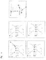
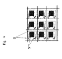
- the device is then in the form of a matrix of spot-shaped probes (corresponding to a hybridization unit), where each spot consists of a type of molecular probe, for example a type of nucleic acid polymer of which the sequence is specific to a gene (it may be for proteins of a particular type of antibody or ligand).
- Each line of spots of the matrix is deposited on a surface of gold or ITO (or any other suitable metal or alloy) delimiting an electrode, the whole of the matrix then consisting of n electrodes corresponding to the number n of lines, each line electrode comprising P spots of grafted probes (cf. fig 7 ).
- the electrodes are etched in a thin layer on an insulating material such as glass, kapton, alumina oxide ... (see diagram).
- a second set of electrodes, mirror of the first one is realized, but this time the electrodes are not grafted with probes, these electrodes are called non-functionalized.
- the two sets of electrodes are arranged opposite each other on the sides of an array of parallel P-capillaries, so that there is one set of electrodes above and one in the other. below ( Fig. 8 and 9 ).
- the first set of functionalized electrodes has grafted electrodes of spot-shaped probes, each probe being capable of retaining a specific molecular target when it is present in the complex mixture, by probe / target specific binding.
- the second set of electrodes has nonfunctional electrodes.
- the set of functionalized electrodes is located above the capillary network and the set of non-functionalized electrodes is located below the capillary network.
- Each capillary is perpendicular to the n electrodes of the set of functionalized electrodes and to the n electrodes of the set of nonfunctionalised electrodes ( Fig. 9 , 10 , 11 ).
- the construction is carried out in such a way that the first spot of the n functionalized electrodes is in the first capillary of the capillary network, the second spot of the n functionalized electrodes is in the second capillary of the capillary network and so on ( Fig. 11 ).
- a pair of electrodes consists of an electrode grafted probes organized into spots above the capillary network and a non-functionalized electrode vis-à-vis below the capillary network.
- the electrodes can be very thin to allow detection by SPR.
- the capillaries converge to a circular reservoir.
- the reservoir comprises an electrode (reservoir electrode), in the same plane as that of the set of functionalized electrodes ( Fig. 11 ).
- this electrode is circular.
- this electrode is located in the center of the ceiling of each tank.
- the set of functionalized electrodes (grafted electrodes of the probes) is completed by two additional connecting electrodes: a first curved electrode is located between the first reservoir electrode and the first functionalized electrode and a second electrode, curved is located between the second reservoir electrode and the last functionalized electrode.
- the connecting electrode is curved, its curvature is defined so that the distances between the connecting electrode and the center of the reservoir (reservoir electrode) are identical at every point of the electrode.
- the first and second additional bonding electrodes are located respectively between the first reservoir electrode and the first functionalized electrode, and between the second reservoir electrode and the last functionalised electrode, so that the shortest distances between the electrode
- the connection and the reservoir electrode are identical at all points of the electrodes.
- the description given above for the device of the invention comprising a double network of capillaries of the elements constituting the network such as capillaries, electrodes, detectors ... can be transposed to the preparation of the device comprising a simple network, under reserve to be compatible with the operation of this single-network device, and adapted if necessary to this structure.
- the description made of the molecules to be analyzed and the probes used, as well as their preparation and their methods of implementation and detection can be transposed to the preparation of the device comprising a simple network, provided that it is compatible with the operation of this single network device, and adapted if necessary to this structure.
- All unhybridized probes at the first line of spots will migrate at the second line of spots.
- the set of migration, relaxation and mixing sequences (points 4 to 6) is applied step by step to hybridize all the spots of all the lines which have complementary targets in the sample analyzed. Once in the second tank, the targets that had migrated into different capillaries mix again. It is then possible according to an alternative embodiment, to perform the electrical potential sequences in the other direction to traverse the network of capillaries in the opposite direction. The back and forth of the targets between the two tanks through the capillaries make it possible to increase the detection sensitivity of the device.
- the first bonding electrode is curved such that the distances between the bonding electrode and the center of the reservoir are identical at every point of the electrode, and in that the second bonding electrode is non-curved.
- This electrode serves as an insurmountable electrical boundary by the probes during hybridization, and then at the detection stage will direct the targets to the delay system using the potentials established by the target electrode and the electrode. link.
- the delay effect is amplified.
- ITO-type alloys that are transparent in the visible (indium oxide and tin oxide or any other equivalent alloy such as, for example, ... ). Since these alloys are highly electrophilic, they must undergo a chemical isolation procedure described in the chapter on chemical isolation.
- the probes can be deposited between the electrodes of the set of functionalized electrodes ( Fig. 7 ).
- the device according to the invention comprises one or more detector (s) suitable for separately collecting the molecular targets and / or for separately analyzing the molecular targets, named hereinafter the detector (s).
- the detector is connected at the output of a lower transverse channel connecting the capillaries of the second network.
- a device comprising a detector and a lower transverse channel connecting all the capillaries of the second network.
- several detectors can be used, each detector being connected at the output of a lower transverse channel connecting a portion of the capillaries of the second network.
- Any detection system can be adapted to the output of the second capillary network, in particular depending on the type of labeling used to differentiate the molecular targets, for example from different samples.
- the detection can be done using a spectrophotometer for exciting and acquiring the fluorescence of labeled molecules or the intrinsic fluorescence of the studied molecules.
- a spectrophotometer for exciting and acquiring the fluorescence of labeled molecules or the intrinsic fluorescence of the studied molecules.
- the natural fluorescence of the studied molecules can be used for detection.
- crystals of NaCl or KCl can be used to carry out infra-red spectrometry or raster spectrometry studies.
- target detection and quantification uses paramagnetic or electron resonance if the targets are labeled with a para-magnetic marker.
- the distal or lower line electrodes consist of a gold plate (or other free electron metal) of a few tens of ⁇ m thick.
- the outer face (opposite to the channels) of each distal electrode is contiguous to one of the three faces of a prism (glass, quartz, plastic or any other transparent material that may be suitable for the SPR).
- the prism consists of a trihedron whose one of the three rectangular faces is coupled to the outer face of a distal electrode, the length of the trihedron corresponding to that of the electrode ( Fig. 15 ).
- the system is energized so that at each pair of line electrodes the potential is positive at the mediating electrode and negative at the distal electrode respectively in the concept of functionalized and nonfunctionalized electrodes.
- the electrode functionalized to the mediating electrode and the non-functionalized electrode to the distal electrode we will assimilate for the description the electrode functionalized to the mediating electrode and the non-functionalized electrode to the distal electrode.
- the potentials will be adapted according to the charge of the molecules studied.
- a chaotropic agent capable of defeating the probe-target complex is introduced into the medium. The probes separate from the targets, but remain retained in each box or spot by the negative charge of the mediating electrode ( Fig. 16 ).
- the potential at the first pair of electrodes is reversed such that it is positive at the distal electrode, and negative at the medial electrode.
- the targets of the line of loci or spots dependent on the pair of electrodes will migrate into the capillary network to come to the level of the distal electrode perpendicular to the capillary network (lower network for the two superposed array system), such as that the probes of each box or spot are found in a different capillary.
- the SPR measurement will be done by the reflection of light on the outer face of the distal electrode, through the prisms arranged on each electrode. It is possible to estimate the dissociation constant by observing the rate at which the SPR signal measured over time varies. By applying an alternating current between a pair of line electrodes, it is possible to measure the association and probe / target dissociation constants. In this particular case the experiments are done without denaturing agent, the local concentration variations induced by the electric field make it possible to carry out the associations and dissociations of the probes and the targets.
- the current applied to the electrodes can disturb the SPR signal.
- the field applied between the pair of line electrodes can be discontinuous.
- the SPR measurement being then only during the field interruption phases, we will speak of SPR pulse measurement coupled to the frequency of the electric field. It is possible to determine the diffusion coefficient of the molecule by analyzing the rates of variation of the SPR signals as a function of the time of interruption of the electric field between the pair of line electrodes. The same operations are renewed for each pair of line electrodes.
- the targets can come into direct contact with the metal, thereby increasing the sensitivity of the detection.
- the electric field makes it possible to concentrate the targets as much as possible at the surface of the metal, which further increases the detection sensitivity.
- the SPR detection being dependent on the mass, the more the molecules to be detected are heavy and the more the detection will be effective. An increase in the mass of the molecules therefore makes it possible to lower the detection threshold.
- the use of targets in which the atoms have been replaced by heavy isotopes makes it possible to increase the molecular weight and thus to lower the detection threshold.
- the chip-implanted electrode system allows direct measurement of the impedance of molecules that attach to a target.
- a cross-electrode system is realized.
- the system consists of two sets of superimposed electrodes located in two different planes below and above a matrix of probe spots.
- the direction of the electrodes of the non-functionalized play is perpendicular to that of the electrodes of the functionalized play ( Fig. 17 ).
- the spots have, for example, implanted on the electrodes of the set functionalized at each intersection of the functionalized electrodes and the projection in the upper plane of the electrodes of the non-functionalized play.
- the attachment of the probes depends on the nature of the electrodes and the nature of the probe molecules (see chapter implantation of the probes and isolation of the electrodes.)
- the DNA molecules it is desirable to constrain as much as possible the conformation of the molecules in order to minimize measurement artifacts due to DNA curvature and intramolecular hybridization, which lead to impedance variations of the same order as for hybridization.
- One solution for constraining the DNA is to adsorb it to the electrode by molecular combing.
- the molecules stretched on the electrode can no longer bend or hybridize against themselves, on the other hand they keep the ability to hybridize with a complementary sequence in solution.
- Another solution is to stretch the probe molecule between a functionalized game electrode and an unfunctionalized game electrode, by fixing these ends to the electrodes.
- the probe oligonucleotides used are functionalized at both the 5 'and 3' ends.
- the function chosen in 5 ' is different from that in 3'. Both types of function have an activation and / or a different catalysis. It is for example chosen 5 'Hs, NH 2 functions with a chemical or light activation and a 3' pyrol function with an electric catalysis.
- the distance between the sets of functionalized and non-functionalized electrodes is chosen such that the molecules are stretched without being able to adopt a particular curvature or perform intramolecular hybridization.
- An alternative is to functionalize the 5 'end of the probe to graft on the functionalized electrode and to add a short sequence (10 to 20 bases) 3' (3 'attachment).
- the sequence of the 3 'attachment is specifically chosen so that there is no hybridization with the targets.
- a sequence complementary to the attachment 3 ' is grafted on the nonfunctional electrode vis-a-vis.
- the probes are hooked to the electrode of the game functionalized by their 5 'end through a chemical bond and to the non-functionalized electrode by the 3' end thanks to the 10 to 20 base pair duplex formed between the attachment and its complementary sequence grafted on the electrode. The probes are thus stretched between the two electrodes, which minimizes intramolecular hybridizations and curvature.
- the electrode chip with the grafted probes can be passively hybridized by simple scattering of the targets at each spot as is done for current biochips.
- active hybridization is preferred by following the method described above.
- a network of capillaries and two reservoirs similar to those described in this previous chapter are arranged between the functionalized and non-functionalized electrode sets. Two reservoir electrodes and two bonding electrodes are added to the functionalized electrode set (see diagram).
- the variation of impedance of each spot makes it possible to determine the quantity of fixed targets.
- the intersection between a functionalized electrode and the projection (in the upper plane) of a non-functionalized electrode is unique and corresponds to a single spot.
- the impedance measurement is performed spot-to-spot by successively applying a difference of electrical potential and an electric current at all possible pairs of electrodes formed by a non-functionalized electrode and a functionalized electrode.
- the grid mesh defines a space where a small electrode (spot electrode) of 10 to 500 ⁇ m is arranged depending on the size of the grid.
- spot electrode a small electrode
- At each grid cell there are arranged one or two field effect transistors such that the gate of the transistor is connected to the horizontal electrode on one side of the mesh, the incoming terminal (source) of the transistor to the vertical electrode on one side of the mesh and the outgoing terminal (drain) of the transistor to the spot electrode.
- a grid whose meshes, defined by the horizontal and vertical electrodes, are occupied by small spot electrodes.
- the spot electrodes are connected to two of the four sides of the mesh by one or two field effect transistors ( Fig. 17, 18 ).
- Molecular probes are grafted at each spot electrode.
- the electrodes of the nonfunctional set are arranged opposite each column of "spot electrodes" and parallel to the vertical electrodes of the functionalized grid.
- Each electrode of the non-functionalized game is connected to ground.
- the set of non-functionalized electrodes may be replaced by a single plate connected to ground.
- the spot electrode is powered whatever the direction of the current. It is therefore necessary to have in the mesh, two field effect transistors which have opposite characteristics, that is to say that when the voltage at the gates of the transistors is zero or negative, the current can pass between the input and the output in one direction for the first transistor and in the other direction for the second transistor. Whatever the current flow direction, the spot electrode is powered. It would be advantageous to introduce transistors allowing current to flow in both directions between the input and the output, such as "nmos” or “pmos” type transistors, but these transistors have an additional terminal and therefore require a horizontal electrode. by mesh to make the connection, which is limiting for miniaturization.
- the electrodes are then not used only to drive hybridization according to the above description of active hybridization (ha)).
- all the circuits and electrodes can be made of transparent alloy such as ITO.
- an alternative to chromophore targeting of targets is to use a nucleic acid fluorescent intercalator.
- Acridines are good candidates, especially acridine orange, which has the particularity of fluorescing differently when it is associated with single-stranded DNA molecules or a DNA / DNA duplex.
- the orange acridine is positively charged which allows to move in an electric field.
- the density of the probes at each spot is determined by acridine labeling and measurement of the fluorescence emitted, the different electric fields applied to eliminate the acridine molecules not attached to the DNA probes.
- the sequence of application of the electric fields is similar to that described in chapter ha, but the direction of the fields is adapted to the load of the molecule that one wants to move.
- This method makes it possible to perform dynamic hybridization measurements and to determine the dissociation (kd) and association (ka) constants between the targets and the probes.
- the measurement of the kd and the ka of a target can be compared to the measurements obtained for the native sequence which makes it possible to highlight the polymorphism.
- a detector used in the device of the invention is a mass spectrometer.
- the mass spectrometer can inform, at the same time, the user on the number of target molecules and the nature of these molecules (molecular weight and under certain conditions their formulas).
- the device may for example comprise a lower transverse channel contiguous to the ElectroSpray Ionization (ESI) ( Kebarle et al.- Anal. Chem. ; 1993; 65 (22); p. 972-986 ) of a mass spectrometer.
- the lower transverse channel is connected to the detector via a piezoelectric or thermal pipette which allows a regular injection into the ElectroSpray.
- micro spray micro ESI
- nano spray nano spray
- pico spray pico ESI
- detectors such as orthogonal acceleration time-of-flight (aoTOF or QTOF) quadrupoles ( Chernushevich et al. - Proceedings of the 43rd ASMS Conference on MS and Allied Topics 1995 Atlantas, Georgia ; Sanzone, G. - Rev. SCi. Instrum, 1970; 41 (5) p. 741 ), can be used in the device of the invention.
- aoTOF or QTOF orthogonal acceleration time-of-flight
- the data on the mass and the charge of the molecular ions and the number of molecular ions make it possible to deduce the nature and the number of each type of molecular targets retained specifically in a given microcolumn.
- the formula of the molecules specifically linked to the probes at the level of each microcolumn can be deduced in particular by the specific labeling of the targets and the decomposition of the molecules during the acquisition of the spectrum by the MS / MS method ( Chernushevich et al. - Proceedings of the 43rd ASMS Conference on MS and Allied Topics 1995 Atlantas, Georgia .).
- the device of the invention it is possible to analyze in parallel, different transcriptomes of different samples.
- the device comprises nucleic acids [immobilized in the boxes or on particles] consisting of a set of nucleic acids, representative of a transcriptome.
- transcriptome representsative of a transcriptome
- the nucleic acids immobilized in the lodge have identical or complementary sequences or hybridize specifically under stringent conditions with messenger RNAs, products of the transcription of the nucleic acid sequences of the genome of a given cell or a set of cells, and are in proportions equivalent to those of the transcripts obtained under particular conditions for said cell or set of cells.
- nucleic acid preparation methods of a transcriptome are described in the examples below.
- the set of nucleic acids representative of a transcriptome is immobilized to particles, said particles being immobilized in the micro-columns by appropriate means.
- the device then makes it possible, by the method described in particular in Example 3 below, to analyze in parallel the different transcriptomes.
- the invention aims in particular, the particles as such comprising a set of immobilized nucleic acids, representative of a transcriptome.
- the set of nucleic acid molecules can in particular be used with the micro-column chip comprising the sets of nucleic acids representative of transcriptomes in each micro-column.
- the device of the invention is characterized in that the molecular probes are peptides or polypeptides, preferably antibodies or their antigen-binding fragments.
- the invention naturally targets the uses of the device for detecting and / or assaying specific RNA and / or DNA molecules contained in a biological sample, in particular in a cell extract, the molecular probes being chosen so that they specifically hybridize with a type of RNA or DNA contained in the biological sample.
- the use of such a device allows in particular the comparative analysis of specific RNA and / or DNA molecules contained in at least two biological samples according to, for example, the method described in Example 4.
- the quantification of the probes makes it possible to provide a signature that is specific to the splicing form of a gene.
- the set of probes consisting of specific probes, each specific probe of a target being of a size different from the other probes and / or marked by a marker specific fluorescence, the detection being carried out after capillary electrophoresis of the probes by means of a suitable spectrophotometer.
- the invention relates to a method thus defined, characterized in that each type of probe of the set of probes is specific and complementary to a type of target to form a stoichiometric mixture.
- the invention also relates to a process as described above, characterized in that each type of probe present in the mixture is unequivocally identifiable by its molecular mass, which is obtained by combining three criteria: the crude formula, the size and possible markings with heavy atoms.
- the invention also relates to a method as described above, characterized in that each type of probe present in the mixture is unambiguously defined by its size and a fluorescence marker.
- transcriptome analysis can be transposed to the analysis of a proteome or the analysis of the loss or gain of one or more genes in a patient.
- the probes are also determined to be representative of the desired targets and each probe type probe set is unequivocally identifiable with respect to other types of probes.
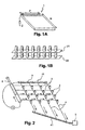
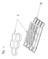
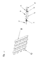
- the micro-column matrix (1) consists of N rows and P columns of micro-columns 50 ⁇ m in diameter and 100 ⁇ m in length, hollowed or molded in the thickness of a glass-like material, silicon or plastic ( Figure 1A ).
- the boxes are perpendicular to the main plane of the chip.
- Each cell is filled with a polyacrylamide gel and the specific molecular probes are immobilized to particles whose diameter is greater than the mesh of the gel.
- the boxes of each row of the micro-column array are connected by a common electrode, forming a row-line electrode (21). This electrode consists of a thin layer of gold, mediating the boxes separating each of them into two half-boxes.
- a second set of electrodes a mirror of the mediating line electrodes, is disposed at the outlet of the cells of the microcolumn matrix, these are the distal line electrodes (22).
- Each distal line electrode is parallel to a medial line electrode forming pairs of line electrodes ( Figure 1 B) . These pairs of electrodes make it possible to apply the desired potential at each line of boxes.
- the distal electrodes are made in the same way as the mediators.
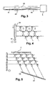
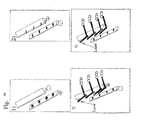
- Each lodge is connected by two channels to the two tiered capillary networks located respectively above and below the plane of the lodges (see figure 2 ):
- the upper capillary network consists of N parallel capillaries (upper capillaries) (3)
- the lower network consists of P parallel capillaries (lower capillaries) (4)
- the N / P arrangement can of course be inverted between two stages of capillaries.
- the same capillary of the upper network is connected to the P cells of a row of the matrix of micro-columns, respectively the same capillary the lower network is connected to the N boxes of a column of the micro-column matrix.
- the connections are made by the connection channels described above, such that the direction between the two networks of lower and upper capillaries is perpendicular.
- each capillary of the upper network is connected with all the capillaries of the lower network by a line of P-cells of the micro-column matrix.
- each capillary of the lower network is connected to all the capillaries of the upper network by a column of N boxes of the micro-column matrix.
- the capillaries have a diameter of between 1 and 100 ⁇ m.
- All capillaries of the upper network opens into a transverse capillary (31) (upper transverse channel) with a diameter of between 2 and 1000 microns.
- the upper transverse channel thus connects all the capillaries of the upper network, it is perpendicular to the direction of the upper network.
- the ends of the capillaries of the upper network opposite to the transverse channel, stop at the last connection with the P th and last boxes of the box lines of the matrix of micro-columns.
- All the capillaries of the lower network opens into a transverse capillary (41) (lower transverse channel) with a diameter of between 2 and 1000 ⁇ m.
- the lower transverse channel thus connects all the capillaries of the lower network.
- the capillaries of the lower network are made such that the path between the connection with the first box of a box column and the lower transverse channel is of different length from one capillary to the other.
- This portion of a capillary of the lower network is called delay.
- the delay is achieved by providing a lower transverse channel at an angle other than 90 ° to the lower capillary network. Depending on the angle chosen, the delays are increasing or decreasing between the successive lower capillaries.
- the end of the capillaries of the network of lower capillaries opposite the transverse channel is connected to a second transverse capillary (7) (secondary lower transverse channel), allowing the establishment of a flow between the two networks of capillaries lower and higher than through the lodge matrix.
- the main lower transverse canal is filled with a liquid gel of capillary electrophoresis to achieve capillary electrophoresis at this level, it is then possible to establish a closed cycle flow between the upper transverse channel and the secondary lower transverse channel ( figure 2 ).
- Electrodes are disposed at the upper and lower transverse channels.
- the upper transverse channel is provided with a piston (6) threaded or not, which can select the number of rows of boxes through which the flow will pass. In retreating, the piston mobilizes more and more lines of boxes of the matrix of micro-columns.
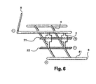
- Detection of the molecules at the outlet of the lower transverse channel is carried out by means of a mass spectrometer (5).
- the lower transverse channel is contiguous to the ElectroSpray Ionization (ESI) (44) of a mass spectrometer ( figure 3 ). It is connected to the detector via a pietzo (43) or thermal pipette that allows a regular injection into the ElectroSpray.
- ESI ElectroSpray Ionization
- the following example illustrates another embodiment of the device according to the invention adapted for the separation and analysis of nucleic acid molecules contained in a biological sample and allowing the denaturation of the molecular targets retained on the micro-columns and their migration to the detector only through the use of electric fields.
- micro-column matrix and the capillary network are substantially identical to Example 1 with the exception of the following differences:
- the device does not include a piston at the upper transverse channel.
- the lower transverse channel and the upper transverse channel are connected to denaturing buffer tanks containing an ammonium hydroxide salt (NH 4 OH).
- Example 3 preparation of a microcolumn containing a set of nucleic acids representative of a transcriptome and its use for the analysis of a transcriptome
- Each microcolumn of the device of the invention comprises a support or particles on which are immobilized all the nucleic acids representative of a transcriptome to be analyzed (DNA, RNA or oligonucleotide ).
- the reverse transcription of the messenger RNA sample to be analyzed is performed from primers such as 5 '(T) 19 X3' where X can be A, C or G.
- the retrotranscription is thus carried out starting from the first nucleotide different from A encountered after the polyA tail.
- the primers described above are previously fixed on said support or said particles, before the retrotranscription.
- the retrotranscription products can also be grafted after retrotranscription on the support.
- the grafting can be provided by biotin-avidin couplings using 5 'biotinylated 5' (T) 19 X3 primers (it is also possible to use a chemical complexation between the particles and the targets).
- the invention relates to a device for separating and / or detecting several molecular targets in solution in a complex mixture, said device comprising a set of magnetic particles on which is immobilized the set of targets representative of a transcriptome to be analyzed, and a set waves.
- Each type of probes in the probe set is specific and complementary to a target type to form a stoichiometric mixture.
- Each type of probe present in the mixture is thus unequivocally identifiable by its molecular mass.
- This specificity of molecular mass is obtained by combining three criteria: the raw formula, the size and possible markings with heavy atoms. The combination of these three criteria makes it possible to produce an astronomical number of probes.
- M n + m + I + j
- the complementary probes hybridize specifically to the target molecules retained on the support or the particles; it is the separation step. Once the system has been rinsed and the unhybridized probes eliminated, the probe molecules hybridized at the level of the support or the particles are denatured in a controlled manner. It is then possible to perform a quantification of each type of hybridized probe molecules on the support or on the particles containing the immobilized targets.
- sequences are hybridized in the presence of small nucleotide polymers (X) n or X represents A, T, G or C and N varying from 3 to 7 nucleotides to form all possible sequences of n nucleotides.
- This method can be applied also for proteins in the context of the study of a proteome.
- the mixture of proteins to be studied is fixed on a support or on particles.
- the targets consist of antibodies or any other specific ligand, the molecular weight of each type of probe will allow their identification unequivocally.
- the probes can be coupled with inert molecules that modify the molecular weight of the probe.
- capillary chromatography is performed prior to injection into the mass spectrometer. This capillary chromatography makes it possible to separate the probes according to their size.
- the mass spectrometer and capillary electrophoresis are coupled with a piezoelectric pipette.
- An alternative of the previous embodiment is to discriminate the probes using fluorescence markers.
- Each type of probe is unequivocally defined by its size and a fluorescence marker.
- the combination of these two criteria makes it possible to achieve a degree of complexity of the order of a thousand by combining, for example, five different fluorescence markers with probes whose sizes are spread between 20 and 200 bases. It is of course possible to increase the complexity of the probe mixture by increasing the allowed size range for the probes and the number of fluorescence markers used.
- the method is adapted to be used directly in solution by using a set of magnetic particles on which the set of targets is immobilized, representative of a transcriptome to be analyzed, and a stoichiometric set of probes as described above.
- the magnetic particles serve to isolate the hybridized probes.
- the hybridized particles are isolated by a magnetic field produced by a single magnet.
- This process replaces a conventional DNA chip, particularly in transcriptome and comparative genomic hybridization (CGH) studies.
- CGH comparative genomic hybridization
- Example 4 Implementation of a micro-column chip as described in Example 1 for the analysis of RNA samples.
- Example 1 makes it possible to analyze a mixture of nucleic acid molecules.
- the analysis can be performed from a single extract of cellular RNA but also from two different extracts.
- At least one of the two mRNA populations should be scored.
- the labeling is carried out by retrotranscription with incorporation of a heavy isotope.
- the heavy isotopes are chosen from: O 18 , O 17 , N 15 , C 13 , H 2 , or any other heavy isotope that can be differentiated by the mass of the common form. These heavy isotopes are incorporated into the nucleotides involved in the synthesis of nucleic acids.
- the second population of mRNA to be analyzed is retro-transcribed into cDNA without the incorporation of heavy atoms, or incorporation of heavy atoms different from those of the first population.
- the primers 5 '(T) 19 X3' where X can take the values A, G or C, are labeled with heavy atoms, different from those possibly used for the rest. of the molecule in the case of a mass spectrometer detection. In fluorescence detection, these primers are labeled with chromophores.
- the two populations of cDNA are mixed equimolarly (it is also possible to treat heterogeneous mRNA / cDNA mixtures).
- the mixture is introduced into a closed circuit which will circulate several times in each microcolumn (see figure 2 ). During their passage in the micro-columns, the targets hybridize to the complementary probes. The circulation inside the closed circuit makes it possible to homogenize the mixture after each passage in the micro-columns.
- a resistor located at the level of the intake pipe for example, makes it possible to regulate the temperature of the hybridization solution, but also to make the thermal variations during the hybridization cycle, this making it possible to control the specificity of the hybridization. .
- a sonication chamber optionally makes it possible to homogenize the size of the molecules to be hybridized by breaking the target cDNAs into molecules of smaller sizes, oligonucleotide probes (between 20 and 100 bp) facilitate the hybridization of the size targets. equivalent.
- the circuit is opened and rinsed thoroughly (washing steps) with a solution eliminating the unhybridized or non-specifically hybridized molecules.
- the system is then coupled to the ElectroSpray of a mass spectrometer, and an electrical potential difference is established between the row electrode pairs of the micro-columns of the matrix, positive at the mediant level and negative at the distal level. Similarly, a difference in electrical potential is established at the level of the transverse channel electrodes, negative at the upper transverse channel and positive at the lower transverse channel. Because of the polarity of the electrodes, the hybridized molecules are maintained in each hybridization box.
- the piston is arranged so that the circulation can be made between the two upper and lower networks only by the micro-columns of the first row of micro-columns of the matrix ( figure 4 ).
- a denaturing solution whose temperature is controlled by the resistance (located for example at the level of the upper transverse channel) is then injected in laminar flow and diffuses through the micro-columns of the first line, the closest to the lower transverse channel, the piston preventing access to other rows of micro-columns.
- the denaturing agent denatures the complexes probe-targets, the electric field prevents the diffusion of the targets out of the boxes.
- Thermal denaturation is also possible as an alternative. By increasing the temperature of the buffer in each microcolumn, the Denaturation of the duplex formed between the fixed probe and the target occurs and the target returns to solution while the probe remains fixed on the matrix.
- the electric field between the pair of electrodes of the first line is then reversed or simply cut off, the electrical potential difference between the pair of electrodes of the transverse channels is maintained ( figure 5 ).
- the targets of each microcolumn of the first line then pass into the corresponding capillaries of the lower network, the probes are transported or electrophoretically migrate through these capillaries to the lower transverse channel.
- the targets of the different micro-columns arrive with different times in the lower transverse channel depending on the respective delays of the capillaries of the lower network. In fact, the different targets arrive in the capillaries of the detector (ElectroSpray) coupled to the lower transverse channel with different times for the analysis. For there to be no mixing between the targets coming from different micro-columns, it is generally necessary to work in very slow laminar flow.
- the use of several probes by microcolumns makes it possible to determine all the forms of splicing of the gene.
- Example 5 Implementation of a micro-column chip as described in Example 2 for the analysis of RNA samples.
- Example 2 the device described in Example 2 will be used.
- the hybridization and rinsing steps are carried out in the same manner as described in Example 4.
- the upper transverse channel is connected to the reservoir of buffer containing the chaotropic agent capable of migrating in a buffer electric field
- the lower transverse channel is connected to the second reservoir containing the same buffer.
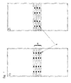
- the electrodes of the upper and lower transverse channel as well as the distal line electrodes are maintained at a negative potential with respect to the median line electrodes which are maintained at a positive potential.
- the migration of ions and chaotic agents, at the anode and at the cathode, the pH of the buffer, as well as the potential difference result in the denaturation of the probe-target biopolymer complexes ( figure 6 ).
- the probes remain fixed on the matrix because of the strong bond with it, the negatively charged and free targets also remain at the positively charged mediating line electrodes.
- the electrodes of the transverse channels are brought to an electrical differential, negative for that of the upper transverse channel and positive for that of the lower channel, the electrical potential being kept positive for the mediators and negative for the electrodes.
- the targets are confined in an electrostatic chamber in each micro-column prohibiting any migration.
- the methods of the invention allow the sequencing of nucleic acid or protein targets separated and analyzed in the mass spectrometer.
- Micro-sequencing involves performing random cleavages in the nucleic acid sequence and then identifying the resulting products by mass spectrometry.
- Random cleavages can be chemical, physical, mechanical or enzymatic.
- the enzymatic breaks may be obtained by the action of an enzymatic mixture consisting of enzymes fixed in a microcolumn, this microcolumn being arranged for example between the detection capillary and the lower transverse channel. When biopolymers go through this micro-column, they are partially degraded. Analysis of the degradation products makes it possible to deduce the sequence.
- Enzymes such as endo-nucleases for nucleic acids, or endo-peptidase for proteins, make it possible, for example, to obtain random cuts in these biopolymers.
- the use of exonucleases for nucleic acids and exopeptidases for proteins allows partial digestions.
- the analysis of the products of these reactions makes it possible to obtain the sequence of biopolymers specifically retained in each of the micro-columns. Chemical cleavages are achieved by controlled chemical degradation of the biopolymers using an acid, a base or any other chemical.
- the 3 'ends of the mRNAs systematically comprise a poly A tail.
- This poly stem can serve as end markers:
- the cDNAs are obtained by retrotranscription with primers such as 5' (T) 19 X 3 'where X can be A, C or G. Retrotranscription is thus performed from the first nucleotide different from A encountered after the polyA tail.
- the 5 '(T) 19 X 3' primers will be labeled with heavy atoms, different from those possibly used for the rest of the molecule.
- the devices are made in a manner similar to those described in Example 1 or 2.
- Each microcolumn of the matrix is filled with antibody specific for one type of polypeptide.
- the antibodies are specific for native or denatured proteins.
- Antibodies are directly attached to the wall of the lodges or to particles retained in each lodge.
- nucleic acids it will be possible to use antibodies bound to a pyrol molecule. All of the methods applied for the pyrole-linked probes described for the nucleic acids are applied to the pyrole bound antibodies.
- the cell extracts of polypeptides are complexed by performing a closed circuit with the micro-column networks. This allows the formation of specific antigen / antibody complexes at each microcolumn.
- buffers allowing the migration of the proteins, solely according to their sizes. These buffers also make it possible to destroy the antibody / antigen complex.
- SDS sodium dodecyl sulfate
- the device may further comprise one or more detector (s) allowing the recovery and / or analysis of different molecular targets.
- Each microcolumn may comprise a tubular box having a diameter of 2 to 1000 microns, preferably about 20 to 100 microns, and a length of 2 to 2000 microns, preferably 40 to 200 microns.
- the micro-column matrix may comprise boxes molded or hollowed out in the thickness of a material forming the plane of the matrix.
- Each capillary network can be hollowed out in the thickness of a plate of a suitable material.
- the matrix may consist of 1 to 1 million micro-columns, preferably 100 to 100000 micro-columns.
- the molecular probes can be immobilized on the inner wall of the micro-columns.
- Each microcolumn can contain particles to which are coupled the molecular probes, said particles being retained in each cell by appropriate means.
- the particles to which the molecular probes are coupled may be of a diameter greater than the diameter of the capillaries at the inlet and the outlet of each microcolumn.
- Each microcolumn can consist of a cell containing a gel in which the molecular probes are immobilized, preventing the migration of said molecular probes out of the cell.
- the molecular probes can be coupled to particles of a diameter greater than the mesh of the gel, preventing their migration out of the box.
- filters may be arranged at the inlet and outlet of each box and the particles may be of a diameter greater than the pore diameters of said filters.
- the device may comprise means for controlling, at the level of one or more specific micro-columns of the matrix, the elution of the molecular targets and / or their migration towards a detector and / or their retention in the micro-columns after elution. .
- the device may comprise an electrode, called a box electrode, placed in contact with each microcolumn, preferably mediating the microcolumn, and a second electrode, called a distal electrode, disposed at the outlet of each microcolumn , allowing the control of the elution of the molecular targets retained in one or more specific micro-columns and / or their migration to a detector or their retention in the micro-columns after elution (point I, see above).
- a box electrode placed in contact with each microcolumn, preferably mediating the microcolumn
- a second electrode called a distal electrode
- the first network of capillaries of the device may comprise a first transverse capillary into which is introduced the complex mixture, hereinafter referred to as an upper transverse channel, with a diameter preferably of between 2 and 1000 ⁇ m, connected to a set of capillaries serving the micro-columns of the matrix and the second capillary network may comprise a set of capillaries connecting each microcolumn to a second transverse capillary, called a lower transverse channel, with a diameter preferably of between 2 and 1000 ⁇ m, said lower transverse channel being connected to an electrode and said upper transverse channel being connected to an electrode (point I, see above).
- the device may comprise means making it possible to control the elution of the molecular targets retained on the micro-columns of a specific line and / or their migration towards a detector and / or their retention in the micro-columns after elution, and the length of each capillary of the second network can be chosen so that the distance between the output of a micro-column and the lower transverse channel is different from one capillary of the second network to another, from increasing or decreasing preference of the capillary connecting the first micro-column of a line to the capillary connecting to the last micro-column of this line, so that the travel times of the molecular targets at the output of the micro-column to a detector are different for each micro-column of the same line (point I, see above).
- the capillary network connecting each microcolumn to the lower transverse channel may comprise P parallel capillaries, each capillary connecting the N micro-columns of the same column of the matrix to the lower transverse channel and forming an angle with said lower transverse channel other than 90 ° (point I, see above).
- the device may comprise, for each line, an electrode connecting all the P micro-columns of the same line, thus forming N row electrodes, preferably mediating microstrips , and a second series of electrodes, parallel to the line electrodes, connecting all the capillaries P out of the micro-columns of the same line, to control the elution and / or migration targets for each line of micro-column (points I and II, see below).
- the first network of capillaries called upper network may comprise N parallel capillaries, each capillary connecting the upper transverse capillary to P micro-columns of the same line of the matrix
- the second network of capillaries called lower network may comprise P parallel capillaries, each capillary connecting the N micro-columns of the same column from the matrix to the lower transverse capillary, the angle formed between the two networks of lower and upper capillaries being different from 0 °, preferably perpendicular (point II, see below).
- the transverse channel connected to the upper network may be associated with a piston allowing the circulation of a mixture introduced into the upper transverse channel in one or more specific capillaries of the upper network (point II, see below).
- the device may comprise a detection device consisting of a mass spectrometer.
- the molecular probes of the device may be nucleic acids, preferably oligonucleotides or DNA fragments.
- the molecular probes can be constituted for each microcolumn of a type of nucleic acid specific for a gene.
- each micro-column may comprise a set of nucleic acids, representative of a transcriptome (point III, see below).
- the set of nucleic acids representative of a transcriptome can be immobilized to particles, said particles being immobilized in the micro-columns by appropriate means (point III, see below).
- the probes of the device may be polypeptides, preferably antibody fragments.
- the set of functionalized electrodes of this second device may be located above the capillary network and the set of non-functionalized electrodes may be located below the capillary network.
- the second device may further comprise a reservoir at each end of the capillary network.
- This reservoir may comprise a circular electrode.
- This circular electrode contained in each reservoir may be located in the same plane as that of the set of functionalized electrodes.
- the second device may further comprise a first and a second additional bonding electrode situated respectively between the first reservoir electrode and the first functionalized electrode, and between the second reservoir electrode and the last functionalized electrode, so that the distances shorter between the connecting electrode and the reservoir electrode are identical at all points of the electrodes.
- the first bonding electrode may be curved
- the second bonding electrode may be non-curved, so that this electrode serves as an insurmountable electrical boundary by the probes during the hybridization, and then at the step of detection will direct targets to the delay system using potentials set by the target electrode and the bonding electrode
- the present application also describes a method of attaching a nucleic acid polymer to an ITO electrode by direct adsorption.
Landscapes
- Chemical & Material Sciences (AREA)
- Health & Medical Sciences (AREA)
- Life Sciences & Earth Sciences (AREA)
- General Health & Medical Sciences (AREA)
- Molecular Biology (AREA)
- Chemical Kinetics & Catalysis (AREA)
- Analytical Chemistry (AREA)
- Physics & Mathematics (AREA)
- Pathology (AREA)
- General Physics & Mathematics (AREA)
- Immunology (AREA)
- Electrochemistry (AREA)
- Dispersion Chemistry (AREA)
- Hematology (AREA)
- Clinical Laboratory Science (AREA)
- Biochemistry (AREA)
- Fluid Mechanics (AREA)
- Measuring Or Testing Involving Enzymes Or Micro-Organisms (AREA)
- Apparatus Associated With Microorganisms And Enzymes (AREA)
- Other Investigation Or Analysis Of Materials By Electrical Means (AREA)
- Investigating Or Analysing Materials By Optical Means (AREA)
- Investigating Or Analyzing Non-Biological Materials By The Use Of Chemical Means (AREA)
- Investigating Or Analysing Biological Materials (AREA)
- Treatment Of Liquids With Adsorbents In General (AREA)
- Investigating Or Analyzing Materials By The Use Of Magnetic Means (AREA)
Applications Claiming Priority (2)
| Application Number | Priority Date | Filing Date | Title |
|---|---|---|---|
| FR0311204A FR2860006B1 (fr) | 2003-09-24 | 2003-09-24 | Dispositif pour separer et/ou analyser plusieurs cibles moleculaires en solution dans un melange complexe |
| EP04786364A EP1668365B1 (de) | 2003-09-24 | 2004-08-27 | Vorrichtung zur trennung und analyse mehrerer in einem komplexen gemisch gelöster molekularer ziele |
Related Parent Applications (1)
| Application Number | Title | Priority Date | Filing Date |
|---|---|---|---|
| EP04786364.2 Division | 2004-08-27 |
Publications (2)
| Publication Number | Publication Date |
|---|---|
| EP2189792A2 true EP2189792A2 (de) | 2010-05-26 |
| EP2189792A3 EP2189792A3 (de) | 2010-09-01 |
Family
ID=34224448
Family Applications (2)
| Application Number | Title | Priority Date | Filing Date |
|---|---|---|---|
| EP10155815A Withdrawn EP2189792A3 (de) | 2003-09-24 | 2004-08-27 | Vorrichtung zur Trennung und/oder Analyse mehrerer in einem komplexen Gemisch gelöster molekülarer Targets |
| EP04786364A Expired - Lifetime EP1668365B1 (de) | 2003-09-24 | 2004-08-27 | Vorrichtung zur trennung und analyse mehrerer in einem komplexen gemisch gelöster molekularer ziele |
Family Applications After (1)
| Application Number | Title | Priority Date | Filing Date |
|---|---|---|---|
| EP04786364A Expired - Lifetime EP1668365B1 (de) | 2003-09-24 | 2004-08-27 | Vorrichtung zur trennung und analyse mehrerer in einem komplexen gemisch gelöster molekularer ziele |
Country Status (11)
| Country | Link |
|---|---|
| US (2) | US7687257B2 (de) |
| EP (2) | EP2189792A3 (de) |
| JP (1) | JP4659748B2 (de) |
| CN (2) | CN102225325B (de) |
| AT (1) | ATE504829T1 (de) |
| CA (2) | CA2746552A1 (de) |
| DE (1) | DE602004032156D1 (de) |
| DK (1) | DK1668365T3 (de) |
| ES (1) | ES2362662T3 (de) |
| FR (1) | FR2860006B1 (de) |
| WO (1) | WO2005036170A2 (de) |
Families Citing this family (10)
| Publication number | Priority date | Publication date | Assignee | Title |
|---|---|---|---|---|
| WO2006090073A2 (fr) * | 2005-02-25 | 2006-08-31 | Comissariat A L'energie Atomique | Procede et dispositif pour separer des cibles moleculaires dans un melange complexe |
| US20100248383A1 (en) * | 2007-11-22 | 2010-09-30 | Koninklijke Philips Electronics N.V. | Combined optical and electrical sensor cartridges |
| FR2958645B1 (fr) | 2010-04-09 | 2012-08-31 | Commissariat Energie Atomique | Hemi-anticorps a auto-assemblage |
| JP5740660B2 (ja) * | 2010-07-02 | 2015-06-24 | 一般社団法人オンチップ・セロミクス・コンソーシアム | 細胞分析装置 |
| CN102533956B (zh) * | 2010-12-22 | 2014-05-14 | 深圳华大基因科技服务有限公司 | 一种提高原核生物转录组高通量测序效率的方法 |
| US9757330B2 (en) | 2013-10-18 | 2017-09-12 | Industrial Technology Research Institute | Recipe for in-situ gel, and implant, drug delivery system formed thereby |
| CN107144603B (zh) * | 2017-05-16 | 2019-10-01 | 安徽师范大学 | 一种基于静电作用的阻抗型电化学生物传感器、制备方法及其应用 |
| CN108593748B (zh) * | 2018-01-26 | 2024-04-30 | 南京溯远基因科技有限公司 | 毛细管及dna测序仪 |
| SG11202110061TA (en) * | 2019-03-11 | 2021-10-28 | Redbud Labs Inc | Methods of surface modification of silicones for specific target and high efficiency binding |
| WO2021158511A1 (en) * | 2020-02-04 | 2021-08-12 | Omniome, Inc. | Flow cells and methods for their manufacture and use |
Citations (1)
| Publication number | Priority date | Publication date | Assignee | Title |
|---|---|---|---|---|
| WO2001081625A1 (fr) * | 2000-04-26 | 2001-11-01 | Ipsogen | Methode de mesure quantitative de l'expression des genes |
Family Cites Families (33)
| Publication number | Priority date | Publication date | Assignee | Title |
|---|---|---|---|---|
| NZ199286A (en) * | 1980-12-22 | 1986-05-09 | Commw Serum Lab Commission | A method of detecting antibodies or an antigenic or haptenic substance in a sample |
| US6391590B1 (en) * | 1991-10-21 | 2002-05-21 | The Regents Of The University Of California | Recombinant streptavidin-metallothionein chimeric protein having biological recognition specificity |
| FR2717011B1 (fr) * | 1994-03-02 | 1996-03-29 | Telemecanique | Conecteur pour canalisation électrique. |
| US5871918A (en) * | 1996-06-20 | 1999-02-16 | The University Of North Carolina At Chapel Hill | Electrochemical detection of nucleic acid hybridization |
| US20070269799A9 (en) * | 1994-06-22 | 2007-11-22 | Zhang David Y | Nucleic acid amplification methods |
| US5872010A (en) * | 1995-07-21 | 1999-02-16 | Northeastern University | Microscale fluid handling system |
| US20020048809A1 (en) * | 1997-06-16 | 2002-04-25 | Lafferty William Micharl | Capillary array-based sample screening |
| US6074827A (en) * | 1996-07-30 | 2000-06-13 | Aclara Biosciences, Inc. | Microfluidic method for nucleic acid purification and processing |
| JP2002503334A (ja) * | 1996-09-04 | 2002-01-29 | テクニカル ユニバーシティ オブ デンマーク | 粒子の分離と分析用のマイクロフローシステム |
| DE69735445T2 (de) * | 1996-12-10 | 2006-08-10 | Sequenom, Inc., San Diego | Abspaltbare, nicht-flüchtige moleküle zur massenmarkierung |
| US6020209A (en) * | 1997-04-28 | 2000-02-01 | The United States Of America As Represented By The Secretary Of The Navy | Microcapillary-based flow-through immunosensor and displacement immunoassay using the same |
| US6106685A (en) * | 1997-05-13 | 2000-08-22 | Sarnoff Corporation | Electrode combinations for pumping fluids |
| US6143152A (en) * | 1997-11-07 | 2000-11-07 | The Regents Of The University Of California | Microfabricated capillary array electrophoresis device and method |
| DE19822123C2 (de) * | 1997-11-21 | 2003-02-06 | Meinhard Knoll | Verfahren und Vorrichtung zum Nachweis von Analyten |
| US6131410A (en) * | 1998-03-16 | 2000-10-17 | The Regents Of The University Of California | Vacuum fusion bonding of glass plates |
| US6294063B1 (en) * | 1999-02-12 | 2001-09-25 | Board Of Regents, The University Of Texas System | Method and apparatus for programmable fluidic processing |
| US6458259B1 (en) * | 1999-05-11 | 2002-10-01 | Caliper Technologies Corp. | Prevention of surface adsorption in microchannels by application of electric current during pressure-induced flow |
| US6676819B1 (en) * | 1999-09-14 | 2004-01-13 | Yaoqing Diana Liu | Methods and apparatus for automatic on-line multi-dimensional electrophoresis |
| US6406604B1 (en) * | 1999-11-08 | 2002-06-18 | Norberto A. Guzman | Multi-dimensional electrophoresis apparatus |
| US20020090649A1 (en) * | 1999-12-15 | 2002-07-11 | Tony Chan | High density column and row addressable electrode arrays |
| ATE386821T1 (de) * | 2000-10-23 | 2008-03-15 | Gen Probe Inc | Zusammensetzungen und methoden zur detektion von humanem immundefizienz virus 2 (hiv-2) |
| US6649419B1 (en) * | 2000-11-28 | 2003-11-18 | Large Scale Proteomics Corp. | Method and apparatus for protein manipulation |
| JP2002202305A (ja) * | 2000-12-28 | 2002-07-19 | Ebara Corp | アフィニテイー検出分析チップ、その作製方法、それを用いる検出方法及び検出システム |
| US20020106644A1 (en) * | 2001-02-05 | 2002-08-08 | Carsten Rosenow | Methods for transcription detection and analysis |
| US20020127740A1 (en) * | 2001-03-06 | 2002-09-12 | Ho Winston Z. | Quantitative microfluidic biochip and method of use |
| WO2003006948A2 (en) * | 2001-07-10 | 2003-01-23 | Wisconsin Alumni Research Foundation | Surface plasmon resonance imaging of micro-arrays |
| US20030044864A1 (en) * | 2001-07-20 | 2003-03-06 | Diversa Corporation | Cellular engineering, protein expression profiling, differential labeling of peptides, and novel reagents therefor |
| WO2003016574A1 (en) * | 2001-08-16 | 2003-02-27 | Zhifeng Shao | Analysis of gene expression profiles using sequential hybridization |
| US6924107B2 (en) * | 2002-01-28 | 2005-08-02 | Bio-Informatics Group, Inc. | Four dimensional biochip design for high throughput applications and methods of using the four dimensional biochip |
| CN1379240A (zh) * | 2002-04-05 | 2002-11-13 | 中国科学院长春应用化学研究所 | 毛细管电泳-固态电化学发光检测器及制备方法 |
| US20040018611A1 (en) * | 2002-07-23 | 2004-01-29 | Ward Michael Dennis | Microfluidic devices for high gradient magnetic separation |
| WO2004059301A1 (en) * | 2002-12-25 | 2004-07-15 | Proteoptics Ltd. | Surface plasmon resonance sensor |
| EP1583950B1 (de) * | 2002-12-26 | 2017-04-05 | Meso Scale Technologies, LLC. | Testkassetten und verfahren zu ihrer verwendung |
-
2003
- 2003-09-24 FR FR0311204A patent/FR2860006B1/fr not_active Expired - Fee Related
-
2004
- 2004-08-27 AT AT04786364T patent/ATE504829T1/de not_active IP Right Cessation
- 2004-08-27 DE DE602004032156T patent/DE602004032156D1/de not_active Expired - Lifetime
- 2004-08-27 CN CN201110153535.9A patent/CN102225325B/zh not_active Expired - Fee Related
- 2004-08-27 CA CA2746552A patent/CA2746552A1/fr not_active Abandoned
- 2004-08-27 CN CN2004800342944A patent/CN1882839B/zh not_active Expired - Fee Related
- 2004-08-27 EP EP10155815A patent/EP2189792A3/de not_active Withdrawn
- 2004-08-27 DK DK04786364.2T patent/DK1668365T3/da active
- 2004-08-27 WO PCT/FR2004/002207 patent/WO2005036170A2/fr not_active Ceased
- 2004-08-27 ES ES04786364T patent/ES2362662T3/es not_active Expired - Lifetime
- 2004-08-27 JP JP2006527437A patent/JP4659748B2/ja not_active Expired - Fee Related
- 2004-08-27 CA CA002539995A patent/CA2539995A1/fr not_active Abandoned
- 2004-08-27 EP EP04786364A patent/EP1668365B1/de not_active Expired - Lifetime
-
2006
- 2006-03-23 US US11/386,781 patent/US7687257B2/en not_active Expired - Fee Related
-
2010
- 2010-02-04 US US12/700,680 patent/US8211693B2/en not_active Expired - Fee Related
Patent Citations (1)
| Publication number | Priority date | Publication date | Assignee | Title |
|---|---|---|---|---|
| WO2001081625A1 (fr) * | 2000-04-26 | 2001-11-01 | Ipsogen | Methode de mesure quantitative de l'expression des genes |
Non-Patent Citations (15)
| Title |
|---|
| "Baffinslane, Chischester, West Sussex", 1995, JOHN WILEY AND SON, pages: 41 - 74 |
| "Dynal AS - Techinical Handbook", 1996, article "Dynal distributors worldwide" |
| BERTUCCI F ET AL., HUM MOL GENET., vol. 8, no. 9, September 1999 (1999-09-01), pages 1715 - 22 |
| CHERNUSHEVICH; GEORGIA; SANZONE, G. ET AL.: "Proceedings of the 43rd ASMS Conference on MS and Allied Topics 1995 Atlantas", REV. SCI. INSTRUM, vol. 41, no. 5, 1970, pages 741 |
| CLUZEL P., SCIENCE, vol. 2071, no. 5250, 1996, pages 792 - 794 |
| EMMETT ET AL., J.AM SOC. MASS SPECTROM, vol. 5, 1994, pages 605 - 613 |
| ERRATUM, HUM MOL GENET, vol. 8, no. 11, October 1999 (1999-10-01), pages 2129 |
| HOEN ET AL., NUCLEIC ACIDS RES., vol. 31, no. 5, 1 March 2003 (2003-03-01), pages 20 |
| HUANG ET AL., ANAL. CHEM., vol. 74, no. 14, 2002, pages 3362 - 3371 |
| KEBARLE ET AL., ANAL. CHEM., vol. 65, no. 22, 1993, pages 972 - 986 |
| KUO ET AL., ANAL. CHEM., vol. 75, no. 10, 2003, pages 2224 - 2230 |
| KUO ET AL., ANAL. CHEM., vol. 75, no. 8, 2003, pages 1861 - 1867 |
| MARTINEZ ET AL., NUCL. ACIDS. RES., vol. 31, 2003, pages 18 |
| OLIVER D J ET AL: "Functional genomics: high-throughput mRNA, protein, and metabolite analyses", METABOLIC ENGINEERING, ACADEMIC PRESS, US, vol. 4, no. 1, 1 January 2002 (2002-01-01), pages 98 - 106, XP002253434, ISSN: 1096-7176, DOI: 10.1006/MBEN.2001.0212 * |
| VALASKOVIC ET AL., ANAL. CHEM., vol. 67, no. 20, 1995, pages 3802 - 3805 |
Also Published As
| Publication number | Publication date |
|---|---|
| WO2005036170A3 (fr) | 2005-08-04 |
| JP2007506956A (ja) | 2007-03-22 |
| ES2362662T3 (es) | 2011-07-11 |
| CN102225325A (zh) | 2011-10-26 |
| US7687257B2 (en) | 2010-03-30 |
| DK1668365T3 (da) | 2011-07-18 |
| CA2746552A1 (fr) | 2005-04-21 |
| FR2860006B1 (fr) | 2006-12-22 |
| JP4659748B2 (ja) | 2011-03-30 |
| FR2860006A1 (fr) | 2005-03-25 |
| CN1882839A (zh) | 2006-12-20 |
| EP2189792A3 (de) | 2010-09-01 |
| US20100203540A1 (en) | 2010-08-12 |
| CN1882839B (zh) | 2011-08-10 |
| ATE504829T1 (de) | 2011-04-15 |
| US8211693B2 (en) | 2012-07-03 |
| CN102225325B (zh) | 2013-05-22 |
| CA2539995A1 (fr) | 2005-04-21 |
| EP1668365B1 (de) | 2011-04-06 |
| DE602004032156D1 (de) | 2011-05-19 |
| EP1668365A2 (de) | 2006-06-14 |
| US20060239864A1 (en) | 2006-10-26 |
| WO2005036170A2 (fr) | 2005-04-21 |
Similar Documents
| Publication | Publication Date | Title |
|---|---|---|
| Lai et al. | Exosome processing and characterization approaches for research and technology development | |
| US8241893B2 (en) | Method and device for separating molecular targets in a complex mixture | |
| US8211693B2 (en) | Device for separating and/or analyzing several molecular targets dissolved in a complex mixture | |
| US8940663B2 (en) | Nano-scale biosensors | |
| CA2539187A1 (en) | Label-free methods for performing assays using a colorimetric resonant reflectance optical biosensor | |
| WO1995022056A1 (fr) | Surfaces hautement specifiques pour reactions biologiques, procede pour leur preparation et procede pour leur utilisation | |
| US20230204562A1 (en) | Nanopore device and methods of detecting charged particles using same | |
| WO2013088098A2 (en) | Efficient ultra-long dna analysis in compact nanofluidic channels | |
| Leith et al. | Free Energy of a Polymer in Slit-like Confinement from the Odijk Regime to the Bulk | |
| Takeishi et al. | Observation of electrostatically released DNA from gold electrodes with controlled threshold voltages | |
| WO2023080102A1 (ja) | 血液中の脳神経細胞由来のエクソソームに結合したアミロイドβの検出方法、血液中の脳神経細胞由来のエクソソームに結合したアミロイドβの検出用キット、及び脳内のアミロイドβの蓄積レベルを評価する方法 | |
| WO2020163789A1 (en) | Single cell/exosome/vesicle protein profiling | |
| US12085572B2 (en) | Protein capture membrane and method of use thereof | |
| FR2882563A1 (fr) | Procede et dispositif pour separer des cibles moleculaires dans un melange complexe | |
| FR2882564A1 (fr) | Procede et dispositif pour separer des cibles moleculaires dans un melange complexe | |
| JP2010511490A (ja) | 予め選択された生体分子の移動度を変化させる作動手段を有するバイオテクノロジー装置 | |
| CN117940579A (zh) | 具有增强的传感功能的核酸纳米孔 | |
| Eberle et al. | On the use of Si-based nanohole arrays as near-field biochips | |
| Le et al. | Characterization of Nucleosomes using DNA Origami |
Legal Events
| Date | Code | Title | Description |
|---|---|---|---|
| PUAI | Public reference made under article 153(3) epc to a published international application that has entered the european phase |
Free format text: ORIGINAL CODE: 0009012 |
|
| 17P | Request for examination filed |
Effective date: 20100308 |
|
| AC | Divisional application: reference to earlier application |
Ref document number: 1668365 Country of ref document: EP Kind code of ref document: P |
|
| AK | Designated contracting states |
Kind code of ref document: A2 Designated state(s): AT BE BG CH CY CZ DE DK EE ES FI FR GB GR HU IE IT LI LU MC NL PL PT RO SE SI SK TR |
|
| RAP1 | Party data changed (applicant data changed or rights of an application transferred) |
Owner name: COMMISSARIAT A L'ENERGIE ATOMIQUE ET AUX ENERGIES |
|
| PUAL | Search report despatched |
Free format text: ORIGINAL CODE: 0009013 |
|
| AK | Designated contracting states |
Kind code of ref document: A3 Designated state(s): AT BE BG CH CY CZ DE DK EE ES FI FR GB GR HU IE IT LI LU MC NL PL PT RO SE SI SK TR |
|
| RIC1 | Information provided on ipc code assigned before grant |
Ipc: C12Q 1/68 20060101ALI20100723BHEP Ipc: G01N 33/543 20060101AFI20100415BHEP |
|
| RIN1 | Information on inventor provided before grant (corrected) |
Inventor name: LEBEAU, JEROME Inventor name: ORY, CATHERINE Inventor name: CHEVILLARD, SYLVIE Inventor name: UGOLIN, NICOLAS |
|
| 17Q | First examination report despatched |
Effective date: 20130130 |
|
| RIC1 | Information provided on ipc code assigned before grant |
Ipc: B01L 3/00 20060101ALI20140512BHEP Ipc: G01N 27/447 20060101ALI20140512BHEP Ipc: G01N 1/40 20060101ALI20140512BHEP Ipc: G01N 33/543 20060101AFI20140512BHEP Ipc: C12Q 1/68 20060101ALI20140512BHEP |
|
| GRAP | Despatch of communication of intention to grant a patent |
Free format text: ORIGINAL CODE: EPIDOSNIGR1 |
|
| INTG | Intention to grant announced |
Effective date: 20140626 |
|
| RIN1 | Information on inventor provided before grant (corrected) |
Inventor name: ORY, CATHERINE Inventor name: LEBEAU, JEROME Inventor name: CHEVILLARD, SYLVIE Inventor name: UGOLIN, NICOLAS |
|
| STAA | Information on the status of an ep patent application or granted ep patent |
Free format text: STATUS: THE APPLICATION IS DEEMED TO BE WITHDRAWN |
|
| 18D | Application deemed to be withdrawn |
Effective date: 20141107 |