EP2189565A2 - Rotary hook for a lockstitch sewing machine, comprising means to reduce the noise thereof - Google Patents
Rotary hook for a lockstitch sewing machine, comprising means to reduce the noise thereof Download PDFInfo
- Publication number
- EP2189565A2 EP2189565A2 EP09176587A EP09176587A EP2189565A2 EP 2189565 A2 EP2189565 A2 EP 2189565A2 EP 09176587 A EP09176587 A EP 09176587A EP 09176587 A EP09176587 A EP 09176587A EP 2189565 A2 EP2189565 A2 EP 2189565A2
- Authority
- EP
- European Patent Office
- Prior art keywords
- basket
- hook body
- hook
- cylindrical cavity
- rotary hook
- Prior art date
- Legal status (The legal status is an assumption and is not a legal conclusion. Google has not performed a legal analysis and makes no representation as to the accuracy of the status listed.)
- Granted
Links
- 238000009958 sewing Methods 0.000 title claims abstract description 16
- 230000005291 magnetic effect Effects 0.000 claims description 17
- 238000004891 communication Methods 0.000 claims description 5
- 238000005461 lubrication Methods 0.000 claims description 2
- 238000000034 method Methods 0.000 claims description 2
- 230000009467 reduction Effects 0.000 description 6
- 230000000694 effects Effects 0.000 description 4
- 230000004048 modification Effects 0.000 description 3
- 238000012986 modification Methods 0.000 description 3
- 229920002994 synthetic fiber Polymers 0.000 description 3
- 230000005294 ferromagnetic effect Effects 0.000 description 2
- 238000004519 manufacturing process Methods 0.000 description 2
- 239000002184 metal Substances 0.000 description 2
- 230000008901 benefit Effects 0.000 description 1
- 230000008878 coupling Effects 0.000 description 1
- 238000010168 coupling process Methods 0.000 description 1
- 238000005859 coupling reaction Methods 0.000 description 1
- 230000001419 dependent effect Effects 0.000 description 1
- 230000007246 mechanism Effects 0.000 description 1
- 239000007769 metal material Substances 0.000 description 1
- 230000003019 stabilising effect Effects 0.000 description 1
- 229920003002 synthetic resin Polymers 0.000 description 1
- 239000000057 synthetic resin Substances 0.000 description 1
Images


Classifications
-
- D—TEXTILES; PAPER
- D05—SEWING; EMBROIDERING; TUFTING
- D05B—SEWING
- D05B57/00—Loop takers, e.g. loopers
- D05B57/08—Loop takers, e.g. loopers for lock-stitch sewing machines
- D05B57/10—Shuttles
- D05B57/14—Shuttles with rotary hooks
-
- D—TEXTILES; PAPER
- D05—SEWING; EMBROIDERING; TUFTING
- D05B—SEWING
- D05B69/00—Driving-gear; Control devices
- D05B69/30—Details
- D05B69/32—Vibration-minimising devices
Definitions
- the present invention refers to a rotary hook for a lockstitch sewing machine, both for home and for industrial use, which comprises means to reduce the noise thereof.
- the invention further refers to a lockstitch sewing machine comprising means to reduce the noise of a rotary hook and to a method for reducing the noise of a rotary hook.
- the rotary hook can be of the type with a horizontal axis of rotation or of the type with a vertical axis of rotation.
- the rotary hook comprises at least one hook body, which is connected to a shaft from which it receives motion and which comprises a cylindrical cavity, a basket free to rotate inside the cylindrical cavity of the hook body, a gib which helps to constrain the basket to the hook body and possibly a bobbin case which is placed inside the basket and which helps to constrain the bobbin to the basket.
- the shaft can be integral with the hook body or housed in a hole present in the centre of the cylindrical cavity.
- the basket is constrained to the hook body by a rib, formed on the outer surface thereof, which engages in a race, formed in the inner wall of the cylindrical cavity of the hook body, which prevents an axial and a radial translation of the basket with respect to the cylindrical cavity, but not a rotation thereof.
- This race of the hook body consists of a C-shaped groove delimited by two plane surfaces parallel to each other and by a cylindrical surface perpendicular to the plane ones.
- the race of the hook body and the rib of the basket must be interrupted for a certain angular sector to allow the needle thread to pass and the stitch to be formed: these interruptions prevent the use of bearings, making necessary a coupling of the sliding type (or with sliding friction) between the race of the hook body and the rib of the basket and also causing, during the rotation of the hook body, noise (due to the play existing between the rib of the basket and the race of the hook body and to the fact that they are habitually made of metal materials) which is enhanced by vibration and resonance phenomena.
- US patent 7171914 (or EP 1640490 ) describes a hook with a vertical axis in which the basket and the hook body are made of synthetic material (synthetic resins) and the basket is constrained to the hook body by magnetic elements inserted in the bottom wall of the basket and on the bottom of the cylindrical cavity of the hook body, allowing the structure of the hook to be simplified (for example, the gib and C-shaped race formed in the inner wall of the cylindrical cavity of the hook body are not provided) and the production costs thereof to be reduced.
- US 4429649 discloses a rotary hook for home sewing machines where the basket (called bobbin case holder) is constrained by a rib, provided on the outer surface of the basket, which engages in a L-shaped race, provided in the inner wall of the cylindrical cavity of the hook body and delimited by only one plane surface and by a cylindrical surface perpendicular to the plane one, suitable to prevent merely the radial translation of the basket in the cylindrical cavity.
- Said basket is free to fluctuate in axial direction and a magnet positioned at the bottom of the cylindrical cavity of the hook body provides to adjust the tension of the lower thread.
- EP 0 489 980 refers to a magnet placed on the bobbin case (called “bobbin holding mechanism”) to adhere the same to the basket (called “bobbin case holder”): the magnet does not influence the basket in relation to the hook body.
- US patent 4577572 describes a rotary hook in which, to reduce the friction between the rib of the basket and the race of the hook body, the rib of the basket is made to "float" in the race of the hook body by means of a cushion of air. The reduction in friction leads to a reduction in the thread tension necessary for stitching and to a reduction in wear on parts.
- US patent 32809 describes a rotary hook in which, to reduce the friction between the rib of the basket and the race of the hook body, the rib of the hook body is made to "float" in the race of the hook body by means of a magnetic bearing. The reduction in friction leads to a reduction in the thread tension necessary for stitching and to a reduction in wear on parts.
- Object of the present invention is to provide a rotary hook comprising means suitable to reduce the noise thereof within negligible noise limits with respect to the noise of the sewing machine; in particular, an object of the present invention is to provide a rotary hook whose noise is less than 45 db even in cases in which, in the absence of the above means, the noise of said hook would exceed 68 db.
- This axial pressure has the effect of stabilising the basket, preventing vibration and resonance thereof.
- said friction tends to be increased and stabilised, by pushing the basket towards a plane surface of the race of the hook body in order to reduce the vibrations (and therefore the noise) of the rotary hook as much as possible.
- An advantage of the rotary hook according to the present invention consists in the fact that it can be applied to all existing sewing machines without having to modify their stitching members and, in the majority of its embodiments, without requiring any modification to a sewing machine available on the market.
- a rotary hook made according to the invention is completely interchangeable with a rotary hook of the prior art, does not require any modification of the areas destined for the passage of the thread and, in the majority of its embodiments, in itself contains all the constructional features necessary to implement the invention.
- Figure1 shows diagrammatically an exploded view of a rotary hook 1 with a horizontal axis of rotation, known to the art, in which only the elements relevant to the present description have been identified by reference numerals:
- Figure 2 shows diagrammatically the rotary hook 1 of Figure 1 assembled and sectioned through a plane passing through its axis of rotation; visible in figure 2 are the hook body 2 comprising the cylindrical cavity 11, the rib 14 of the basket 6, the race 10 of the hook body in which the rib 14 of the basket 6 is engaged, the bottom wall 15 of the basket 6 and the central hole 17 of the cylindrical cavity 11 able to accommodate a shaft (omitted for the sake of simplicity of the graphic representation) from which the hook 1 receives motion; in a different embodiment, on the other hand, the shaft is integral with the hook 1 (see Figures 3 and 10 ).
- the rotary hook 1 comprises means suitable to apply an axial pressure on the basket 6 such as to cause the rib 14 of the basket 6 to lean against one of the plane surfaces delimiting the race 10 present in the cylindrical cavity 11 of the hook body 2.
- the axial pressure is preferably created by applying to the basket 6 a force of not more than 50 grams (0.49 N).
- the means able to apply said axial pressure to the basket 6 comprise at least one magnetic element, which can:
- This "vacuum” effect sucks the basket 6 towards the hook body 2 and can be obtained by means of:
- the air sucked by the fan 16 can exit through the axial hole 9' of the shaft 9 ( Figure 18 ) or through radial holes 19 which connect the central hole 17 of the hook body 2 to the outer surface 18 of the hook body 2, also obtaining a centrifugal effect ( Figure 19 ).
- the apertures normally present on the sides of the cylindrical cavity 11, which serve to reduce the weight of the hook body 2 and to balance it, can be omitted.
- the means suitable to apply the axial pressure to the basket 6 are suitable to convey onto the basket 6 or onto the bobbin case 5 contained therein a jet of compressed air in an axial direction with respect to the basket 6, by means of
Landscapes
- Engineering & Computer Science (AREA)
- Textile Engineering (AREA)
- Mechanical Engineering (AREA)
- Sewing Machines And Sewing (AREA)
Abstract
Description
- The present invention refers to a rotary hook for a lockstitch sewing machine, both for home and for industrial use, which comprises means to reduce the noise thereof.
- The invention further refers to a lockstitch sewing machine comprising means to reduce the noise of a rotary hook and to a method for reducing the noise of a rotary hook.
- The rotary hook can be of the type with a horizontal axis of rotation or of the type with a vertical axis of rotation.
- Lockstitch sewing machines and the associated rotary hooks are well known and therefore will not be described herein, where it will merely be recalled that the rotary hook comprises at least one hook body, which is connected to a shaft from which it receives motion and which comprises a cylindrical cavity, a basket free to rotate inside the cylindrical cavity of the hook body, a gib which helps to constrain the basket to the hook body and possibly a bobbin case which is placed inside the basket and which helps to constrain the bobbin to the basket.
- The shaft can be integral with the hook body or housed in a hole present in the centre of the cylindrical cavity.
- The basket is constrained to the hook body by a rib, formed on the outer surface thereof, which engages in a race, formed in the inner wall of the cylindrical cavity of the hook body, which prevents an axial and a radial translation of the basket with respect to the cylindrical cavity, but not a rotation thereof.
- This race of the hook body consists of a C-shaped groove delimited by two plane surfaces parallel to each other and by a cylindrical surface perpendicular to the plane ones.
- The race of the hook body and the rib of the basket must be interrupted for a certain angular sector to allow the needle thread to pass and the stitch to be formed: these interruptions prevent the use of bearings, making necessary a coupling of the sliding type (or with sliding friction) between the race of the hook body and the rib of the basket and also causing, during the rotation of the hook body, noise (due to the play existing between the rib of the basket and the race of the hook body and to the fact that they are habitually made of metal materials) which is enhanced by vibration and resonance phenomena.
- In the current state of the art, it is not possible to eliminate said play and the causes of the noise are so interdependent with each other that they cannot be identified with certainty or eliminated by adopting suitable geometric shapes and/or by imposing more restrictive dimensional or surface tolerances, which would in any case increase the production cost of the rotary hook.
-
US patent 7171914 (orEP 1640490 ) describes a hook with a vertical axis in which the basket and the hook body are made of synthetic material (synthetic resins) and the basket is constrained to the hook body by magnetic elements inserted in the bottom wall of the basket and on the bottom of the cylindrical cavity of the hook body, allowing the structure of the hook to be simplified (for example, the gib and C-shaped race formed in the inner wall of the cylindrical cavity of the hook body are not provided) and the production costs thereof to be reduced. -
US 4429649 discloses a rotary hook for home sewing machines where the basket (called bobbin case holder) is constrained by a rib, provided on the outer surface of the basket, which engages in a L-shaped race, provided in the inner wall of the cylindrical cavity of the hook body and delimited by only one plane surface and by a cylindrical surface perpendicular to the plane one, suitable to prevent merely the radial translation of the basket in the cylindrical cavity. - Said basket is free to fluctuate in axial direction and a magnet positioned at the bottom of the cylindrical cavity of the hook body provides to adjust the tension of the lower thread.
-
EP 0 489 980 refers to a magnet placed on the bobbin case (called "bobbin holding mechanism") to adhere the same to the basket (called "bobbin case holder"): the magnet does not influence the basket in relation to the hook body. -
US patent 4577572 describes a rotary hook in which, to reduce the friction between the rib of the basket and the race of the hook body, the rib of the basket is made to "float" in the race of the hook body by means of a cushion of air. The reduction in friction leads to a reduction in the thread tension necessary for stitching and to a reduction in wear on parts. -
US patent 32809 describes a rotary hook in which, to reduce the friction between the rib of the basket and the race of the hook body, the rib of the hook body is made to "float" in the race of the hook body by means of a magnetic bearing. The reduction in friction leads to a reduction in the thread tension necessary for stitching and to a reduction in wear on parts. - Object of the present invention is to provide a rotary hook comprising means suitable to reduce the noise thereof within negligible noise limits with respect to the noise of the sewing machine; in particular, an object of the present invention is to provide a rotary hook whose noise is less than 45 db even in cases in which, in the absence of the above means, the noise of said hook would exceed 68 db.
- This object has been achieved by means of the rotary hook of
independent claim 1, which comprises means suitable to apply to the basket an axial pressure which obliges the rib of the basket to lean against one of the two plane surfaces of the race present in the cylindrical cavity of the hook body, instead of vibrating freely in said race because of the play always present between said rib and said race. - This axial pressure has the effect of stabilising the basket, preventing vibration and resonance thereof.
- Further advantageous characteristics form the subject matter of the dependent claims.
- In previously cited
US patent 7171914 (orEP 1640490 ) magnets are used to constrain to the hook body a basket made of synthetic material, which would otherwise be free to float, because of the simplification of the hook structure (L-shaped race instead of C-shaped race and related absence of the gib). This invention does not concern the problem of the noise in that, by using a basket and a hook body of synthetic material, the noise produced during the rotation of the hook body is already per se minimal. - In previously cited
US 4429649 a magnet is used to adjust the tension of the lower thread. Also this patent, as the previously citedUS patent 7171914 , refers to a hook with a L-shaped race. - In previously cited
EP 0 489 980 a magnet is used to adhere the bobbin case to the basket, but the magnet does not influence the basket in relation to the hook body and cannot influence the noise produced. - In previously cited
US patents 4577572 and32809 magnets or air jets are used to reduce the friction between the rib of the basket and the race of the hook body and, consequently, to reduce the thread tension necessary for stitching and the wear on parts. - In the present invention, said friction tends to be increased and stabilised, by pushing the basket towards a plane surface of the race of the hook body in order to reduce the vibrations (and therefore the noise) of the rotary hook as much as possible.
- An advantage of the rotary hook according to the present invention consists in the fact that it can be applied to all existing sewing machines without having to modify their stitching members and, in the majority of its embodiments, without requiring any modification to a sewing machine available on the market.
- Furthermore, a rotary hook made according to the invention is completely interchangeable with a rotary hook of the prior art, does not require any modification of the areas destined for the passage of the thread and, in the majority of its embodiments, in itself contains all the constructional features necessary to implement the invention.
- The invention will now be described with reference to exemplifying but non limiting embodiments, described in the appended figures, wherein:
-
Figure 1 shows diagrammatically an exploded view of a rotary hook of the prior art; -
Figure 2 shows diagrammatically the rotary hook ofFigure 1 assembled and sectioned along a plane passing through its axis of rotation; -
Figures 3-16 show diagrammatically various embodiments of a rotary hook according to the invention, in which magnetic means are provided to reduce noise; -
Figures 17-19 show diagrammatically three further embodiments of a rotary hook according to the invention, in which a depressurisation is used to reduce the noise; -
Figures 20 and 21 show diagrammatically two further embodiments of a rotary hook according to the invention, in which jets of air are used to reduce the noise. - In the appended figures, corresponding elements will be identified by like reference numerals.
-
Figure1 shows diagrammatically an exploded view of arotary hook 1 with a horizontal axis of rotation, known to the art, in which only the elements relevant to the present description have been identified by reference numerals: - a
hook body 2, comprising acylindrical cavity 11 which, in the example shown, has a central hole 17 (Figure 2 ) suitable to receive a shaft (omitted for the sake of simplicity of the graphic representation) from which thehook 1 receives motion; in a different embodiment, the shaft is integral with the hook 1 (seeFigures 3 and10 ); - a
basket 6, free to rotate inside thecylindrical cavity 11 to which it is constrained by arib 14 formed on the outer surface of thebasket 6, - a C-
shaped race 10, formed in the inside wall of thecylindrical cavity 11 of thehook body 2 and delimited by two plane surfaces parallel with each other (one of which is partially formed by the gib 110) and by a cylindrical surface perpendicular to the plane ones, in which therib 14 of thebasket 6 engages with a small amount of play (from about 0,01 mm to about 0,1 mm) to prevent an axial and a radial translation of thebasket 6 in thecylindrical cavity 11; - a
bobbin 4, carried by thebasket 6 or possibly by abobbin case 5 set inside thebasket 6. -
Figure 2 shows diagrammatically therotary hook 1 ofFigure 1 assembled and sectioned through a plane passing through its axis of rotation; visible infigure 2 are thehook body 2 comprising thecylindrical cavity 11, therib 14 of thebasket 6, therace 10 of the hook body in which therib 14 of thebasket 6 is engaged, thebottom wall 15 of thebasket 6 and thecentral hole 17 of thecylindrical cavity 11 able to accommodate a shaft (omitted for the sake of simplicity of the graphic representation) from which thehook 1 receives motion; in a different embodiment, on the other hand, the shaft is integral with the hook 1 (seeFigures 3 and10 ). - The
rotary hook 1 according to the present invention comprises means suitable to apply an axial pressure on thebasket 6 such as to cause therib 14 of thebasket 6 to lean against one of the plane surfaces delimiting therace 10 present in thecylindrical cavity 11 of thehook body 2. - The axial pressure is preferably created by applying to the basket 6 a force of not more than 50 grams (0.49 N).
- In a preferred embodiment of a
rotary hook 1 according to the invention, schematically described inFigures 3-16 , the means able to apply said axial pressure to thebasket 6 comprise at least one magnetic element, which can: - A) be fixed with respect to the
hook body 2, attract the basket 6 (which is metal and therefore ferromagnetic) and consist of:- A.1) a disk-
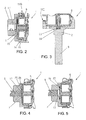
shaped magnet 23, set in ablind recess 24 provided on the bottom of thecylindrical cavity 11 of thehook body 2, as shown inFigure 3 , where theshaft 9 is fixed with respect to thehook body 2, or else of - A.2) a disk-
shaped magnet 25, set in arecess 26 provided on the bottom of thecylindrical cavity 11 of thehook body 2 to close acentral hole 17 in which theshaft 9 is housed (Figure 4 ), or, in a different embodiment of therotary hook 1, to close the central hole of the lubrication system (represented, for example, inFigure 10 ) or else of - A.3) a ring-
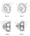
shaped magnet 27, set in acircular recess 28 provided on the bottom of thecylindrical cavity 11 of thehook body 2 and concentric to the axis of rotation of the hook body 2 (Figures 5 ,6 ), thecircular recess 28 not modifying thecentral hole 17, if any, of thehook body 2, or else of - A.4) a series of
cylindrical magnets 29, set in a series ofblind recesses 30 or of through holes set at regular intervals on the bottom of thecylindrical cavity 11 of thehook body 2 and suitable to develop a constant force having axial symmetry with respect to the rotation axis of the hook body (Figure 7 ), theblind recesses 30 or the through holes not modifying thecentral hole 17, if any, of thehook body 2;
- A.1) a disk-
- B) be fixed with respect to the
basket 6, attract thebasket 6 towards thehook body 2 or the shaft 9 (which are metal and therefore ferromagnetic) and consist of:- B.1) a disk-
shaped magnet 32 set in ablind recess 33 provided in thebottom wall 15 of thebasket 6 and aligned with the axis of the basket 6 (Figure 8 ), or else of - B.2) a
magnetic post 35 set aligned with the basket 6 (Figure 9 ), thepost 35 also serving for braking thebobbin 4 to prevent undesired rotations thereof, or else of - B.3) a magnetic extractor 36 (if the
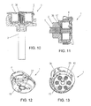
basket 6 has an extractor) set aligned with the axis of the basket 6 (Figure 10 ), themagnetic extractor 36 also serving for braking thebobbin 4 to prevent undesired rotations thereof, or else of - B.4) a ring-
shaped magnet 37, set in acircular recess 38 formed in thebottom wall 15 of thebasket 6 and aligned with the axis of the basket 6 (Figures 11, 12 ), or else of - B.5) a series of
cylindrical magnets 39, set in a series of blind recesses or throughholes 41 set at regular intervals on thebottom wall 15 of thebasket 6 and able to develop a constant force having axial symmetry with respect to the axis of the basket 6 (Figure 13 ), thecylindrical magnets 39 also serving for braking thebobbin 4 to prevent undesired rotations thereof;
- B.1) a disk-
- C) be fixed with respect to the
shaft 9 and consist of a disk-shaped magnet 31, set on top of said shaft and aligned or slightly sunk with respect to the surface of thecylindrical cavity 11 of thehook body 2, which attracts the basket 6 (Figure 14 ); - D) be set in the lockstitch sewing machine near the
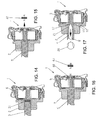
basket 6 or near thebobbin case 5 contained therein and consist of:- D.1) a
magnet 42, which attracts thebasket 6 or thebobbin case 5 contained therein (Figure 15 ), or else of - D.2) a
first magnet 43, which interacts with asecond magnet 44, mounted on thebasket 6 or on thebobbin case 5 contained therein, which has a polarity of the same sign towards thefirst magnet 43 to repel thebasket 6 from the first magnet 43 (Figure 16 ).
- D.1) a
- In other embodiments of a
rotary hook 1 according to the invention, diagrammatically illustrated inFigures 17-19 , the means suitable to apply to the axial pressure on thebasket 6 are able to create a depressurisation between thebottom wall 15 of thebasket 6 and thecylindrical cavity 11 of thehook body 2. - This "vacuum" effect sucks the
basket 6 towards thehook body 2 and can be obtained by means of: - a
nozzle 21, set on the end of theshaft 9 and in communication with thecylindrical cavity 11 of thehook body 2, connected to avacuum pump 20 by means of an axial hole 9' formed in the shaft 9 (Figure 17 ); or else - a
fan 16, mounted in thecentral hole 17 of the hook body 2 (Figures 18 and 19 ) or on the end of theshaft 9, which is in communication with thecylindrical cavity 11 of thehook body 2 through saidcentral hole 17 to suck the air from thecylindrical cavity 11. - The air sucked by the
fan 16 can exit through the axial hole 9' of the shaft 9 (Figure 18 ) or throughradial holes 19 which connect thecentral hole 17 of thehook body 2 to theouter surface 18 of thehook body 2, also obtaining a centrifugal effect (Figure 19 ). - In order to improve the "vacuum" effect, the apertures normally present on the sides of the
cylindrical cavity 11, which serve to reduce the weight of thehook body 2 and to balance it, can be omitted. - In a further embodiment of a
rotary hook 1 according to the invention, diagrammatically described inFigures 20 and 21 , the means suitable to apply the axial pressure to thebasket 6 are suitable to convey onto thebasket 6 or onto thebobbin case 5 contained therein a jet of compressed air in an axial direction with respect to thebasket 6, by means of - a
nozzle 121, connected to acompressor 200, which sends a jet of compressed air onto thebasket 6 in an axial direction (Figure 20 ), or else - a
nozzle 221, set at the end of theshaft 9 in communication with thecylindrical cavity 11 of thehook body 2 and connected to thecompressor 200 by means of an axial hole 9' provided in the shaft 9 (Figure 21 ). - Obviously, the invention is not limited to the particular embodiments previously described and illustrated in the appended figures, but numerous modifications of detail within the reach of a person skilled in the art can be made thereto, without thereby departing from the scope of the invention, as set forth in the appended claims.
Claims (12)
- Rotary hook (1) for a lockstitch sewing machine, comprising at least a hook body (2), in turn comprising a cylindrical cavity (11) and a basket (or bobbin case holder) (6), which is free to rotate inside the cylindrical cavity (11) of the hook body (2) to which it is constrained by a rib (14), provided on the outer surface of the basket (6), which engages with play in a C-shaped race (10), provided in the inner wall of the cylindrical cavity (11) of the hook body (2) and delimited by two plane surfaces parallel to each other and by a cylindrical surface perpendicular to said plane surfaces, to prevent the axial and radial translation of the basket (6) in the cylindrical cavity (11), the hook body (2) being connected to a shaft (9) from which it receives motion, said rotary hook (1) being characterized by comprising means (23; 25; 27; 29; 32; 35; 36; 37; 39; 31; 16; 21; 121; 221; 20; 200) applying an axial pressure on the basket (6) to cause the rib (14) of the basket (6) to lean against one of said plane surfaces delimiting the C-shaped race (10) of the hook body (2) to reduce the noise of the rotary hook (1) caused by the vibration of the basket due to said play.
- Rotary hook (1) as per Claim 1, characterized in that said means (23; 25; 27; 29; 32; 35; 36; 37; 39; 31) suitable to apply an axial pressure on the basket (6) comprise at least one magnetic element.
- Rotary hook (1) as per Claim 2, characterized in that said at least one magnetic element (23, 25, 27, 29) is fixed with respect to the hook body (2), attracts the basket (6) and consists of:- a disk-shaped magnet (23) set in a recess (24) provided on the bottom of the cylindrical cavity (11) of the hook body (2) (Figure 3); or else of- a disk-shaped magnet (25), set in a recess (26) provided on the bottom of the cylindrical cavity (11) of the hook body (2) to close a central hole (17) in which the shaft (9) is housed (Figure 4) or a central hole of the lubrication system; or else of- a ring-shaped magnet (27) set in a circular recess (28) provided on the bottom of the cylindrical cavity (11) of the hook body (2) and centred on the rotation axis of the hook body (2) (Figures 5, 6); or else of- a plurality of cylindrical magnets (29) set in a plurality of recesses (30) or of through holes set at regular intervals on the bottom of the cylindrical cavity (11) of the hook body (2) and suitable to develop a constant force having axial symmetry with respect to the rotation axis of the hook body (2) (Figure 7).
- Rotary hook (1) as per Claim 2, characterized in that said at least one magnetic element (32, 35, 36, 37, 39) is fixed with respect to the basket (6), attracts the basket (6) towards the bottom of the cylindrical cavity (11) of the hook body (2) and consists of:- a disk-shaped magnet (32), set in a recess (33) provided in the bottom wall (15) of the basket (6) and aligned with the axis of the basket (6) (Figure 8); or else of- a magnetic post (35), set aligned with the axis of the basket (6), said magnetic post (35) being also suitable to brake the bobbin (4) to prevent undesired rotations thereof (Figure 9); or else of- a magnetic extractor (36), set aligned with the axis of the basket (6), said magnetic extractor (36) being also suitable to brake the bobbin (4) to prevent undesired rotations thereof (Figure 10); or else of- a ring-shaped magnet (37), set in a circular recess (38) made in the bottom wall (15) of the basket (6) and aligned with the axis of the basket (6) (Figures 11, 12); or else of- a plurality of cylindrical magnets (39), set in a plurality of recesses or of through holes (41), which are set at regular intervals in the bottom wall (15) of the basket (6) and which are able to develop a constant force having axial symmetry with respect to the axis of the basket (6), said cylindrical magnets (39) being also suitable to brake the bobbin (4) to prevent undesired rotations thereof (Figure 13).
- Rotary hook (1) as per Claim 2, characterized in that said at least one magnetic element consists of a magnet (31), fixed with respect to the shaft (9) of the hook body (2) and set on top of said shaft, which attracts the basket (6) (Figure 14).
- Rotary hook (1) as per Claim 1, characterized in that the means (16, 20; 21) suitable to apply an axial pressure on the basket (6), are means suitable to create a depressurisation between the bottom wall (15) of the basket (6) and the cylindrical cavity (11) of the hook body (2).
- Rotary hook (1) as per Claim 6, characterized in that the means suitable to create the depressurisation between the bottom wall (15) of the basket (6) and the cylindrical cavity (11) consist of a nozzle (21), set on the end of the shaft (9) and in communication with the cylindrical cavity (11) of the hook body (2), connected to a vacuum pump (20) through the axial hole (9') of the shaft (9) (Figure 17).
- Rotary hook (1) as per Claim 6, characterized in that said means suitable to create a depressurisation between the bottom wall (15) of the basket (6) and the cylindrical cavity (11) consist of a fan (16) suitable to suck in air from the cylindrical cavity (11) of the hook body (2), the air sucked in by the fan (16) exiting through an axial hole (9') made in the shaft (9) or through radial holes (19) that connect a central hole (17) of the hook body (2) to the outer surface (18) of the hook body (2) (Figures 18, 19).
- Rotary hook (1) as per Claim 1, characterized in that the means (121; 200; 221) suitable to apply an axial pressure on the basket (6) are means suitable to convey onto the basket (6) or onto the bobbin case (5) contained therein, a jet of compressed air in axial direction with respect to the basket (6), and consist of:- a nozzle (121), connected to a compressor (200), which sends a jet of compressed air onto the basket (6) in axial direction (Figure 20); or else of- a nozzle (221), set at the end of the shaft (9) in communication with the cylindrical cavity (11) of the hook body (2) and connected to a compressor (200) by means of an axial hole (9') provided in the shaft (9) (Figure 21).
- Lockstitch sewing machine comprising means for reducing the noise of a rotary hook (1) as per at least one of the preceding claims.
- Lockstitch sewing machine comprising magnetic means for reducing the noise of a rotary hook (1) by applying an axial pressure on the basket (6) of the rotary hook(1) to cause a rib (14) of the basket (6) to lean against one of two plane surfaces, parallel each other, delimiting a C-shaped race (10) provided in the inner wall of the rotary hook body (2), said magnetic means consisting of:- a magnet (42) set in the lockstitch sewing machine, which attracts the basket (6) or the bobbin case (5) contained therein (Figure 15); or else of- a first magnet (43) set in the lockstitch sewing machine, which interacts with a second magnet (44) mounted on the basket (6) or on the bobbin case (5) contained therein, the second magnet (44) having a polarity of the same sign towards said first magnet (43) (Figure 16).
- Method for reducing the noise of a rotary hook (1) as per Claim 1, characterized in that applied on the basket (6) of the rotary hook (1) is an axial pressure suitable to cause the rib (14) of the basket (6) to lean against one of the plane surfaces delimiting the race (10) of the hook body (2).
Applications Claiming Priority (1)
| Application Number | Priority Date | Filing Date | Title |
|---|---|---|---|
| ITMI2008A002105A IT1392162B1 (en) | 2008-11-25 | 2008-11-25 | ROTARY CROCHET FOR SEWING MACHINE WITH POINTED TAPES INCLUDING MEANS TO REDUCE ITS NOISE |
Publications (3)
| Publication Number | Publication Date |
|---|---|
| EP2189565A2 true EP2189565A2 (en) | 2010-05-26 |
| EP2189565A3 EP2189565A3 (en) | 2010-08-18 |
| EP2189565B1 EP2189565B1 (en) | 2014-01-01 |
Family
ID=41130009
Family Applications (1)
| Application Number | Title | Priority Date | Filing Date |
|---|---|---|---|
| EP09176587.5A Active EP2189565B1 (en) | 2008-11-25 | 2009-11-20 | Rotary hook for a lockstitch sewing machine, comprising means to reduce the noise thereof |
Country Status (5)
| Country | Link |
|---|---|
| US (1) | US8342110B2 (en) |
| EP (1) | EP2189565B1 (en) |
| JP (1) | JP5525245B2 (en) |
| CN (1) | CN101736535B (en) |
| IT (1) | IT1392162B1 (en) |
Cited By (1)
| Publication number | Priority date | Publication date | Assignee | Title |
|---|---|---|---|---|
| DE102014102756A1 (en) | 2013-03-04 | 2014-09-04 | Cm Cerliani S.R.L. | Noise-reduced rotary gripper with bobbin case for a lockstitch sewing machine |
Families Citing this family (7)
| Publication number | Priority date | Publication date | Assignee | Title |
|---|---|---|---|---|
| JP6452309B2 (en) * | 2014-04-24 | 2019-01-16 | 蛇の目ミシン工業株式会社 | Sewing machine horizontal rotary hook |
| JP6359867B2 (en) * | 2014-04-24 | 2018-07-18 | 蛇の目ミシン工業株式会社 | Sewing machine horizontal rotary hook |
| DE102015111580A1 (en) * | 2014-08-05 | 2016-02-11 | Cm Cerliani S.R.L. | Gripper for a lockstitch sewing machine with stable tension of the bobbin thread |
| US9797077B2 (en) * | 2015-02-09 | 2017-10-24 | Cm Cerliani S.R.L. | Hook for lockstitch sewing machine comprising a bobbin case with a slide composed of multiple components |
| GB201803199D0 (en) * | 2018-02-27 | 2018-04-11 | Michel Van De Wiele | A tufting machine |
| USD953010S1 (en) * | 2018-12-04 | 2022-05-31 | Cm Cerliani S.R.L. | Bobbin case |
| CN110735250A (en) * | 2019-11-26 | 2020-01-31 | 浙江华洋缝制有限公司 | kinds of shuttle core sleeve and its making method |
Citations (5)
| Publication number | Priority date | Publication date | Assignee | Title |
|---|---|---|---|---|
| US32809A (en) | 1861-07-09 | Improvement in machinery for plowing and tilling land | ||
| US4429649A (en) | 1980-09-26 | 1984-02-07 | Janome Sewing Machine Industry Co., Ltd. | Assembly for lower thread tension adjustment of sewing machine |
| US4577572A (en) | 1983-09-06 | 1986-03-25 | Hirose Manufacturing Company Limited | Fully rotating hook for a lock stitch sewing machine |
| EP0489980A1 (en) | 1990-12-13 | 1992-06-17 | Hirose Manufacturing Company Limited | Bobbin holding structure |
| US7171914B2 (en) | 2004-09-28 | 2007-02-06 | Brother Kogyo Kabushiki Kaisha | Horizontal rotary hook for sewing machine |
Family Cites Families (8)
| Publication number | Priority date | Publication date | Assignee | Title |
|---|---|---|---|---|
| IT998910B (en) * | 1972-10-24 | 1976-02-20 | Manta Sa | ROTATING ONE FOR SEWING MACHINES |
| JPS58216090A (en) * | 1982-06-10 | 1983-12-15 | 蛇の目ミシン工業株式会社 | Apparatus for controlling tension of lower yarn of sewing machine |
| JPH0632730B2 (en) * | 1984-08-31 | 1994-05-02 | 蛇の目ミシン工業株式会社 | Thread tension setting sewing machine |
| JPS61268292A (en) * | 1985-05-23 | 1986-11-27 | 蛇の目ミシン工業株式会社 | Needle and bobbin thread regulator of sewing machine |
| JPH07144081A (en) * | 1993-11-24 | 1995-06-06 | Brother Ind Ltd | Sewing machine |
| US6257512B1 (en) * | 1998-12-16 | 2001-07-10 | Fil-Tec, Inc. | Magnetized pre-wound sideless bobbins |
| JP3420548B2 (en) * | 2000-03-15 | 2003-06-23 | 株式会社廣瀬製作所 | Vertical full rotation kettle |
| DE10028231B4 (en) * | 2000-05-27 | 2004-11-04 | Philipp Moll | Device on sewing or embroidery machines for changing the bobbin for the hook thread |
-
2008
- 2008-11-25 IT ITMI2008A002105A patent/IT1392162B1/en active
-
2009
- 2009-11-20 EP EP09176587.5A patent/EP2189565B1/en active Active
- 2009-11-24 JP JP2009266233A patent/JP5525245B2/en active Active
- 2009-11-25 US US12/625,616 patent/US8342110B2/en active Active
- 2009-11-25 CN CN2009102265951A patent/CN101736535B/en active Active
Patent Citations (5)
| Publication number | Priority date | Publication date | Assignee | Title |
|---|---|---|---|---|
| US32809A (en) | 1861-07-09 | Improvement in machinery for plowing and tilling land | ||
| US4429649A (en) | 1980-09-26 | 1984-02-07 | Janome Sewing Machine Industry Co., Ltd. | Assembly for lower thread tension adjustment of sewing machine |
| US4577572A (en) | 1983-09-06 | 1986-03-25 | Hirose Manufacturing Company Limited | Fully rotating hook for a lock stitch sewing machine |
| EP0489980A1 (en) | 1990-12-13 | 1992-06-17 | Hirose Manufacturing Company Limited | Bobbin holding structure |
| US7171914B2 (en) | 2004-09-28 | 2007-02-06 | Brother Kogyo Kabushiki Kaisha | Horizontal rotary hook for sewing machine |
Cited By (1)
| Publication number | Priority date | Publication date | Assignee | Title |
|---|---|---|---|---|
| DE102014102756A1 (en) | 2013-03-04 | 2014-09-04 | Cm Cerliani S.R.L. | Noise-reduced rotary gripper with bobbin case for a lockstitch sewing machine |
Also Published As
| Publication number | Publication date |
|---|---|
| IT1392162B1 (en) | 2012-02-22 |
| EP2189565B1 (en) | 2014-01-01 |
| JP5525245B2 (en) | 2014-06-18 |
| CN101736535B (en) | 2013-11-06 |
| US8342110B2 (en) | 2013-01-01 |
| US20100126399A1 (en) | 2010-05-27 |
| ITMI20082105A1 (en) | 2010-05-26 |
| JP2010155070A (en) | 2010-07-15 |
| EP2189565A3 (en) | 2010-08-18 |
| CN101736535A (en) | 2010-06-16 |
Similar Documents
| Publication | Publication Date | Title |
|---|---|---|
| EP2189565B1 (en) | Rotary hook for a lockstitch sewing machine, comprising means to reduce the noise thereof | |
| JP5406294B2 (en) | Lower thread tension control device for sewing machine and sewing machine | |
| JP4450198B2 (en) | Horizontal rotary hook | |
| WO2008010821A2 (en) | Oscillation scan mirror with improved accuracy | |
| US10677289B2 (en) | Method for supporting a spinning rotor and bearing system, spinning rotor and support bearings | |
| US9850608B2 (en) | Rotary hook with bobbin case for a lockstitch sewing machine including means to reduce the plays between bobbin case and basket and to reduce the noise thereof | |
| CN105002673B (en) | The horizontal rotary hook of sewing machine | |
| US7253544B2 (en) | Spindle motor with arrangement capable of inhibiting half-omega whirl induced during operation | |
| JP2005318687A (en) | Brushless motor | |
| CN211367953U (en) | Sewing machine | |
| JP3420548B2 (en) | Vertical full rotation kettle | |
| JP5147518B2 (en) | Lower thread tension control device | |
| EP2784913A2 (en) | Direct drive motor | |
| US20200271109A1 (en) | Piston drive device | |
| CN214924793U (en) | Valve inside notching device | |
| JP2006141800A (en) | Horizontal hook of sewing machine | |
| US7076180B1 (en) | Toner cartridge | |
| CN210438940U (en) | Sewing machine | |
| KR102037318B1 (en) | Laundry Treating Apparatus | |
| US5294067A (en) | Method of preventing rotational vibrations in a thread storage and feed device and a thread storage and feed device | |
| CN112144192A (en) | Sewing machine | |
| EP1796994A1 (en) | Yarn feeding device | |
| CN115787262A (en) | Washing machine | |
| KR20170006357A (en) | Bobbin fixing device of yarn winder for sewing machine | |
| TW202005899A (en) | Thread feeding device and method for operating a thread feeding device |
Legal Events
| Date | Code | Title | Description |
|---|---|---|---|
| PUAI | Public reference made under article 153(3) epc to a published international application that has entered the european phase |
Free format text: ORIGINAL CODE: 0009012 |
|
| AK | Designated contracting states |
Kind code of ref document: A2 Designated state(s): AT BE BG CH CY CZ DE DK EE ES FI FR GB GR HR HU IE IS IT LI LT LU LV MC MK MT NL NO PL PT RO SE SI SK SM TR |
|
| AX | Request for extension of the european patent |
Extension state: AL BA RS |
|
| PUAL | Search report despatched |
Free format text: ORIGINAL CODE: 0009013 |
|
| AK | Designated contracting states |
Kind code of ref document: A3 Designated state(s): AT BE BG CH CY CZ DE DK EE ES FI FR GB GR HR HU IE IS IT LI LT LU LV MC MK MT NL NO PL PT RO SE SI SK SM TR |
|
| AX | Request for extension of the european patent |
Extension state: AL BA RS |
|
| 17P | Request for examination filed |
Effective date: 20110216 |
|
| 17Q | First examination report despatched |
Effective date: 20130306 |
|
| GRAP | Despatch of communication of intention to grant a patent |
Free format text: ORIGINAL CODE: EPIDOSNIGR1 |
|
| INTG | Intention to grant announced |
Effective date: 20130910 |
|
| GRAS | Grant fee paid |
Free format text: ORIGINAL CODE: EPIDOSNIGR3 |
|
| GRAA | (expected) grant |
Free format text: ORIGINAL CODE: 0009210 |
|
| AK | Designated contracting states |
Kind code of ref document: B1 Designated state(s): AT BE BG CH CY CZ DE DK EE ES FI FR GB GR HR HU IE IS IT LI LT LU LV MC MK MT NL NO PL PT RO SE SI SK SM TR |
|
| REG | Reference to a national code |
Ref country code: GB Ref legal event code: FG4D |
|
| REG | Reference to a national code |
Ref country code: CH Ref legal event code: EP |
|
| REG | Reference to a national code |
Ref country code: IE Ref legal event code: FG4D |
|
| REG | Reference to a national code |
Ref country code: DE Ref legal event code: R096 Ref document number: 602009021114 Country of ref document: DE Effective date: 20140213 |
|
| REG | Reference to a national code |
Ref country code: AT Ref legal event code: REF Ref document number: 647669 Country of ref document: AT Kind code of ref document: T Effective date: 20140215 |
|
| REG | Reference to a national code |
Ref country code: CH Ref legal event code: NV Representative=s name: BOHEST AG, CH |
|
| REG | Reference to a national code |
Ref country code: NL Ref legal event code: VDEP Effective date: 20140101 |
|
| REG | Reference to a national code |
Ref country code: AT Ref legal event code: MK05 Ref document number: 647669 Country of ref document: AT Kind code of ref document: T Effective date: 20140101 |
|
| REG | Reference to a national code |
Ref country code: LT Ref legal event code: MG4D |
|
| PG25 | Lapsed in a contracting state [announced via postgrant information from national office to epo] |
Ref country code: LT Free format text: LAPSE BECAUSE OF FAILURE TO SUBMIT A TRANSLATION OF THE DESCRIPTION OR TO PAY THE FEE WITHIN THE PRESCRIBED TIME-LIMIT Effective date: 20140101 Ref country code: IS Free format text: LAPSE BECAUSE OF FAILURE TO SUBMIT A TRANSLATION OF THE DESCRIPTION OR TO PAY THE FEE WITHIN THE PRESCRIBED TIME-LIMIT Effective date: 20140501 |
|
| REG | Reference to a national code |
Ref country code: CH Ref legal event code: PCAR Free format text: NEW ADDRESS: HOLBEINSTRASSE 36-38, 4051 BASEL (CH) |
|
| PG25 | Lapsed in a contracting state [announced via postgrant information from national office to epo] |
Ref country code: ES Free format text: LAPSE BECAUSE OF FAILURE TO SUBMIT A TRANSLATION OF THE DESCRIPTION OR TO PAY THE FEE WITHIN THE PRESCRIBED TIME-LIMIT Effective date: 20140101 Ref country code: SE Free format text: LAPSE BECAUSE OF FAILURE TO SUBMIT A TRANSLATION OF THE DESCRIPTION OR TO PAY THE FEE WITHIN THE PRESCRIBED TIME-LIMIT Effective date: 20140101 Ref country code: AT Free format text: LAPSE BECAUSE OF FAILURE TO SUBMIT A TRANSLATION OF THE DESCRIPTION OR TO PAY THE FEE WITHIN THE PRESCRIBED TIME-LIMIT Effective date: 20140101 Ref country code: NL Free format text: LAPSE BECAUSE OF FAILURE TO SUBMIT A TRANSLATION OF THE DESCRIPTION OR TO PAY THE FEE WITHIN THE PRESCRIBED TIME-LIMIT Effective date: 20140101 Ref country code: FI Free format text: LAPSE BECAUSE OF FAILURE TO SUBMIT A TRANSLATION OF THE DESCRIPTION OR TO PAY THE FEE WITHIN THE PRESCRIBED TIME-LIMIT Effective date: 20140101 Ref country code: PT Free format text: LAPSE BECAUSE OF FAILURE TO SUBMIT A TRANSLATION OF THE DESCRIPTION OR TO PAY THE FEE WITHIN THE PRESCRIBED TIME-LIMIT Effective date: 20140502 Ref country code: CY Free format text: LAPSE BECAUSE OF FAILURE TO SUBMIT A TRANSLATION OF THE DESCRIPTION OR TO PAY THE FEE WITHIN THE PRESCRIBED TIME-LIMIT Effective date: 20140101 |
|
| PG25 | Lapsed in a contracting state [announced via postgrant information from national office to epo] |
Ref country code: BE Free format text: LAPSE BECAUSE OF FAILURE TO SUBMIT A TRANSLATION OF THE DESCRIPTION OR TO PAY THE FEE WITHIN THE PRESCRIBED TIME-LIMIT Effective date: 20140101 Ref country code: HR Free format text: LAPSE BECAUSE OF FAILURE TO SUBMIT A TRANSLATION OF THE DESCRIPTION OR TO PAY THE FEE WITHIN THE PRESCRIBED TIME-LIMIT Effective date: 20140101 Ref country code: LV Free format text: LAPSE BECAUSE OF FAILURE TO SUBMIT A TRANSLATION OF THE DESCRIPTION OR TO PAY THE FEE WITHIN THE PRESCRIBED TIME-LIMIT Effective date: 20140101 |
|
| REG | Reference to a national code |
Ref country code: DE Ref legal event code: R097 Ref document number: 602009021114 Country of ref document: DE |
|
| PG25 | Lapsed in a contracting state [announced via postgrant information from national office to epo] |
Ref country code: CZ Free format text: LAPSE BECAUSE OF FAILURE TO SUBMIT A TRANSLATION OF THE DESCRIPTION OR TO PAY THE FEE WITHIN THE PRESCRIBED TIME-LIMIT Effective date: 20140101 Ref country code: EE Free format text: LAPSE BECAUSE OF FAILURE TO SUBMIT A TRANSLATION OF THE DESCRIPTION OR TO PAY THE FEE WITHIN THE PRESCRIBED TIME-LIMIT Effective date: 20140101 Ref country code: DK Free format text: LAPSE BECAUSE OF FAILURE TO SUBMIT A TRANSLATION OF THE DESCRIPTION OR TO PAY THE FEE WITHIN THE PRESCRIBED TIME-LIMIT Effective date: 20140101 Ref country code: RO Free format text: LAPSE BECAUSE OF FAILURE TO SUBMIT A TRANSLATION OF THE DESCRIPTION OR TO PAY THE FEE WITHIN THE PRESCRIBED TIME-LIMIT Effective date: 20140101 |
|
| PLBE | No opposition filed within time limit |
Free format text: ORIGINAL CODE: 0009261 |
|
| STAA | Information on the status of an ep patent application or granted ep patent |
Free format text: STATUS: NO OPPOSITION FILED WITHIN TIME LIMIT |
|
| PG25 | Lapsed in a contracting state [announced via postgrant information from national office to epo] |
Ref country code: SK Free format text: LAPSE BECAUSE OF FAILURE TO SUBMIT A TRANSLATION OF THE DESCRIPTION OR TO PAY THE FEE WITHIN THE PRESCRIBED TIME-LIMIT Effective date: 20140101 Ref country code: PL Free format text: LAPSE BECAUSE OF FAILURE TO SUBMIT A TRANSLATION OF THE DESCRIPTION OR TO PAY THE FEE WITHIN THE PRESCRIBED TIME-LIMIT Effective date: 20140101 |
|
| 26N | No opposition filed |
Effective date: 20141002 |
|
| REG | Reference to a national code |
Ref country code: DE Ref legal event code: R097 Ref document number: 602009021114 Country of ref document: DE Effective date: 20141002 |
|
| PG25 | Lapsed in a contracting state [announced via postgrant information from national office to epo] |
Ref country code: SI Free format text: LAPSE BECAUSE OF FAILURE TO SUBMIT A TRANSLATION OF THE DESCRIPTION OR TO PAY THE FEE WITHIN THE PRESCRIBED TIME-LIMIT Effective date: 20140101 |
|
| PG25 | Lapsed in a contracting state [announced via postgrant information from national office to epo] |
Ref country code: MC Free format text: LAPSE BECAUSE OF FAILURE TO SUBMIT A TRANSLATION OF THE DESCRIPTION OR TO PAY THE FEE WITHIN THE PRESCRIBED TIME-LIMIT Effective date: 20140101 Ref country code: LU Free format text: LAPSE BECAUSE OF FAILURE TO SUBMIT A TRANSLATION OF THE DESCRIPTION OR TO PAY THE FEE WITHIN THE PRESCRIBED TIME-LIMIT Effective date: 20141120 |
|
| GBPC | Gb: european patent ceased through non-payment of renewal fee |
Effective date: 20141120 |
|
| REG | Reference to a national code |
Ref country code: IE Ref legal event code: MM4A |
|
| REG | Reference to a national code |
Ref country code: FR Ref legal event code: ST Effective date: 20150731 |
|
| PG25 | Lapsed in a contracting state [announced via postgrant information from national office to epo] |
Ref country code: IE Free format text: LAPSE BECAUSE OF NON-PAYMENT OF DUE FEES Effective date: 20141120 Ref country code: GB Free format text: LAPSE BECAUSE OF NON-PAYMENT OF DUE FEES Effective date: 20141120 |
|
| PG25 | Lapsed in a contracting state [announced via postgrant information from national office to epo] |
Ref country code: FR Free format text: LAPSE BECAUSE OF NON-PAYMENT OF DUE FEES Effective date: 20141201 |
|
| PG25 | Lapsed in a contracting state [announced via postgrant information from national office to epo] |
Ref country code: NO Free format text: LAPSE BECAUSE OF FAILURE TO SUBMIT A TRANSLATION OF THE DESCRIPTION OR TO PAY THE FEE WITHIN THE PRESCRIBED TIME-LIMIT Effective date: 20140401 Ref country code: SM Free format text: LAPSE BECAUSE OF FAILURE TO SUBMIT A TRANSLATION OF THE DESCRIPTION OR TO PAY THE FEE WITHIN THE PRESCRIBED TIME-LIMIT Effective date: 20140101 |
|
| PG25 | Lapsed in a contracting state [announced via postgrant information from national office to epo] |
Ref country code: IT Free format text: LAPSE BECAUSE OF FAILURE TO SUBMIT A TRANSLATION OF THE DESCRIPTION OR TO PAY THE FEE WITHIN THE PRESCRIBED TIME-LIMIT Effective date: 20140101 Ref country code: GR Free format text: LAPSE BECAUSE OF FAILURE TO SUBMIT A TRANSLATION OF THE DESCRIPTION OR TO PAY THE FEE WITHIN THE PRESCRIBED TIME-LIMIT Effective date: 20140402 Ref country code: BG Free format text: LAPSE BECAUSE OF FAILURE TO SUBMIT A TRANSLATION OF THE DESCRIPTION OR TO PAY THE FEE WITHIN THE PRESCRIBED TIME-LIMIT Effective date: 20140101 |
|
| PG25 | Lapsed in a contracting state [announced via postgrant information from national office to epo] |
Ref country code: HU Free format text: LAPSE BECAUSE OF FAILURE TO SUBMIT A TRANSLATION OF THE DESCRIPTION OR TO PAY THE FEE WITHIN THE PRESCRIBED TIME-LIMIT; INVALID AB INITIO Effective date: 20091120 Ref country code: TR Free format text: LAPSE BECAUSE OF FAILURE TO SUBMIT A TRANSLATION OF THE DESCRIPTION OR TO PAY THE FEE WITHIN THE PRESCRIBED TIME-LIMIT Effective date: 20140101 Ref country code: MT Free format text: LAPSE BECAUSE OF FAILURE TO SUBMIT A TRANSLATION OF THE DESCRIPTION OR TO PAY THE FEE WITHIN THE PRESCRIBED TIME-LIMIT Effective date: 20140101 |
|
| PG25 | Lapsed in a contracting state [announced via postgrant information from national office to epo] |
Ref country code: MK Free format text: LAPSE BECAUSE OF FAILURE TO SUBMIT A TRANSLATION OF THE DESCRIPTION OR TO PAY THE FEE WITHIN THE PRESCRIBED TIME-LIMIT Effective date: 20140101 |
|
| P01 | Opt-out of the competence of the unified patent court (upc) registered |
Effective date: 20230525 |
|
| PGFP | Annual fee paid to national office [announced via postgrant information from national office to epo] |
Ref country code: DE Payment date: 20231120 Year of fee payment: 15 Ref country code: CH Payment date: 20231201 Year of fee payment: 15 |