JP5525245B2 - Rotary hook for lockstitch machine with means to reduce noise - Google Patents
Rotary hook for lockstitch machine with means to reduce noise Download PDFInfo
- Publication number
- JP5525245B2 JP5525245B2 JP2009266233A JP2009266233A JP5525245B2 JP 5525245 B2 JP5525245 B2 JP 5525245B2 JP 2009266233 A JP2009266233 A JP 2009266233A JP 2009266233 A JP2009266233 A JP 2009266233A JP 5525245 B2 JP5525245 B2 JP 5525245B2
- Authority
- JP
- Japan
- Prior art keywords
- basket
- hook body
- hook
- magnet
- rotary hook
- Prior art date
- Legal status (The legal status is an assumption and is not a legal conclusion. Google has not performed a legal analysis and makes no representation as to the accuracy of the status listed.)
- Active
Links
- 230000005291 magnetic effect Effects 0.000 claims description 42
- 238000009958 sewing Methods 0.000 claims description 19
- 238000005461 lubrication Methods 0.000 claims description 2
- 238000000034 method Methods 0.000 claims description 2
- 238000010586 diagram Methods 0.000 description 39
- 230000000694 effects Effects 0.000 description 5
- 229920002994 synthetic fiber Polymers 0.000 description 3
- 230000005294 ferromagnetic effect Effects 0.000 description 2
- 238000004519 manufacturing process Methods 0.000 description 2
- 239000002184 metal Substances 0.000 description 2
- 239000000470 constituent Substances 0.000 description 1
- 230000008878 coupling Effects 0.000 description 1
- 238000010168 coupling process Methods 0.000 description 1
- 238000005859 coupling reaction Methods 0.000 description 1
- 230000001419 dependent effect Effects 0.000 description 1
- 239000007769 metal material Substances 0.000 description 1
- 230000005855 radiation Effects 0.000 description 1
- 230000000087 stabilizing effect Effects 0.000 description 1
- 229920003002 synthetic resin Polymers 0.000 description 1
- 239000000057 synthetic resin Substances 0.000 description 1
Images


Classifications
-
- D—TEXTILES; PAPER
- D05—SEWING; EMBROIDERING; TUFTING
- D05B—SEWING
- D05B57/00—Loop takers, e.g. loopers
- D05B57/08—Loop takers, e.g. loopers for lock-stitch sewing machines
- D05B57/10—Shuttles
- D05B57/14—Shuttles with rotary hooks
-
- D—TEXTILES; PAPER
- D05—SEWING; EMBROIDERING; TUFTING
- D05B—SEWING
- D05B69/00—Driving-gear; Control devices
- D05B69/30—Details
- D05B69/32—Vibration-minimising devices
Landscapes
- Engineering & Computer Science (AREA)
- Textile Engineering (AREA)
- Mechanical Engineering (AREA)
- Sewing Machines And Sewing (AREA)
Description
本発明は、ノイズを低減する手段を備える、家庭用および工業用本縫いミシン用のロータリーフックに関する。 The present invention relates to a rotary hook for household and industrial lockstitch sewing machines provided with means for reducing noise.
本発明はさらに、ロータリーフックのノイズを低減する手段を備える本縫いミシンと、ロータリーフックのノイズを低減する方法とに関する。 The present invention further relates to a lockstitch sewing machine provided with means for reducing noise on the rotary hook and a method for reducing noise on the rotary hook.
ロータリーフックは、回転水平軸を有する種類でもよいし、または回転縦軸を有する種類のものでもよい。 The rotary hook may be of the type having a rotating horizontal axis or of the type having a rotating vertical axis.
本縫いミシンとそれに関連するロータリーフックは公知であり、それゆえここでは詳述せず、ロータリーフックが少なくとも1つのフック体を有していることを再確認するのみとする。フック体は、その動きを支持するシャフトに接続されており、円筒状キャビティーと、フック体の円筒状キャビティーの中で自由に回転するバスケットと、バスケットをフック体に押さえつける役割を有するジブと、場合によっては、バスケットの中に位置しており、ボビンをバスケットに押さえつける役割を有するボビンケースとを備える。 Lockstitch sewing machines and associated rotary hooks are well known, and therefore will not be described in detail here, only to reconfirm that the rotary hook has at least one hook body. The hook body is connected to a shaft that supports its movement, and includes a cylindrical cavity, a basket that freely rotates in the cylindrical cavity of the hook body, and a jib that serves to press the basket against the hook body. In some cases, a bobbin case is located in the basket and serves to press the bobbin against the basket.
シャフトはフック体と一体化され得る。または円筒状キャビティーの中央にある穴に通され得る。 The shaft can be integrated with the hook body. Or it can be passed through a hole in the center of the cylindrical cavity.
バスケットは、リブによってフック体に押さえつけられる。リブは、バスケットの外側表面に形成されており、案内溝に係合する。案内溝は、フック体の円筒状キャビティーの内壁に形成され、バスケットにおける円筒状キャビティーに向かう軸方向および放射状の動きを防止する。しかし、バスケットの回転は妨げない。 The basket is pressed against the hook body by ribs. The rib is formed on the outer surface of the basket and engages with the guide groove. The guide groove is formed on the inner wall of the cylindrical cavity of the hook body and prevents axial and radial movement of the basket toward the cylindrical cavity. However, the rotation of the basket is not hindered.
フック体の案内溝は、互いに平行な2つの平面および該平面に垂直な円筒状表面によって定められるC型溝からなる。 The guide groove of the hook body is composed of a C-shaped groove defined by two planes parallel to each other and a cylindrical surface perpendicular to the plane.
フック体の案内溝とバスケットのリブとは、特定の角度領域において針糸を通過して縫い目を形成することを可能にするため、隔たりを有する必要がある。この隔たりがベアリングの使用を妨げるため、フック体の案内溝とバスケットのリブとの間の滑り型(または滑り摩擦)の結合が必要となる。また、フック体が回転している間、ノイズ(バスケットのリブとフック体の案内溝との間の遊びによるノイズ、またそれらが一般的に金属物質からなることによるノイズ)が生じる。該ノイズは、振動および共鳴現象によって増幅される。 The guide groove of the hook body and the rib of the basket need to have a gap in order to allow the needle thread to pass through and form a seam in a specific angular region. Since this gap prevents the use of the bearing, a sliding type (or sliding friction) coupling between the guide groove of the hook body and the rib of the basket is required. Further, while the hook body is rotating, noise (noise due to play between the ribs of the basket and the guide groove of the hook body, and noise due to the fact that they are generally made of a metal material) is generated. The noise is amplified by vibration and resonance phenomena.
当分野においては現状、このような動きを取り除くことは不可能である。また、ノイズの原因は相互依存しており、理由を特定できない。また、この動きは適切な幾何学的形状を採用することによっても取り除くことができず、かつ/またはより限定的な寸法または表面許容度を加えることによっても取り除くことができない。いずれにしても、ロータリーフックの製造コストが増加してしまう。 At present, it is impossible to remove such movement in this field. Moreover, the causes of noise are interdependent, and the reason cannot be specified. Also, this movement cannot be removed by adopting a suitable geometric shape and / or by adding more restrictive dimensions or surface tolerances. In any case, the manufacturing cost of the rotary hook increases.
米国特許7171914(またはEP 1640490)が示すフックは、垂直軸を有し、バスケットとフック体とは合成物質(合成樹脂)からなる。また、バスケットが、バスケットの底面壁に挿入された磁力エレメントによってフック体に押さえつけられるため、フック体の円筒状キャビティーの底面においては、フックの構造を単純化できる(例えば、フック体の円筒状キャビティーの内壁におけるジブおよびC型案内溝を設けない)。このため、製造コストも低減できる。 The hook shown in US Pat. No. 7,171,914 (or EP 1640490) has a vertical axis, and the basket and hook body are made of a synthetic material (synthetic resin). Further, since the basket is pressed against the hook body by a magnetic element inserted into the bottom wall of the basket, the hook structure can be simplified on the bottom surface of the cylindrical cavity of the hook body (for example, the cylindrical shape of the hook body). Jib and C-shaped guide groove on the inner wall of the cavity are not provided). For this reason, manufacturing cost can also be reduced.
US4429649は、家庭用ミシンのロータリーフックを開示しており、バスケット(ボビンケースホルダーと称される)が、リブによって押さえつけられている。上記リブはバスケットの外側表面に設けられ、L型案内溝に係合する。該案内溝は、フック体の円筒状キャビティーの内壁に設けられ、1つの平面と、上記平面に垂直の円筒状表面によって定められる。これは、円筒状キャビティー内のバスケットが単に放射移動することを防止するのに適切である。 US4429649 discloses a rotary hook for a household sewing machine, in which a basket (referred to as a bobbin case holder) is pressed by a rib. The rib is provided on the outer surface of the basket and engages with the L-shaped guide groove. The guide groove is provided on the inner wall of the cylindrical cavity of the hook body, and is defined by one plane and a cylindrical surface perpendicular to the plane. This is adequate to prevent the basket in the cylindrical cavity from simply radiating.
上記バスケットは、軸方向に自由に移動し、フック体の円筒状キャビティーの底面に位置する磁石は、下糸の緊張を調節する。 The basket moves freely in the axial direction, and a magnet located on the bottom surface of the cylindrical cavity of the hook body adjusts the tension of the lower thread.
EP 0 489 980は、ボビンケース(「ボビン支持機構」と称される」に配置される磁石に関する。上記磁石は、ボビンケースをバスケット(「ボビンケースホルダー」と称される)にはりつけるためのものである。上記磁石は、フック体と相互に関連してバスケットに影響を及ぼすことはない。 EP 0 489 980 relates to a magnet arranged in a bobbin case (referred to as “bobbin support mechanism”), which is for attaching the bobbin case to a basket (referred to as “bobbin case holder”). The magnet does not affect the basket relative to the hook body.
米国特許4577572はロータリーフックについて開示している。ロータリーフックでは、バスケットのリブとフック体の案内溝との間の摩擦を低減するため、バスケットのリブが、エアクッションによってフック体の案内溝において「浮く」。摩擦が低減すれば、本縫いのために必要な糸の緊張も低減する。パーツの磨耗も低減する。 U.S. Pat. No. 4,577,572 discloses a rotary hook. In the rotary hook, in order to reduce the friction between the rib of the basket and the guide groove of the hook body, the rib of the basket “floats” in the guide groove of the hook body by the air cushion. If the friction is reduced, the tension of the thread necessary for the main sewing is also reduced. Parts wear is also reduced.
米国特許32809は、ロータリーフックについて開示している。該ロータリーフックでは、バスケットのリブとフック体の案内溝との間の摩擦を低減するため、フック体のリブが、磁針方位によってフック体の案内溝において「浮く」。摩擦を低減すると、本縫いのために必要な糸の緊張も低減する。パーツの磨耗も低減する。 U.S. Pat. No. 32809 discloses a rotary hook. In the rotary hook, in order to reduce the friction between the rib of the basket and the guide groove of the hook body, the rib of the hook body “floats” in the guide groove of the hook body by the magnetic needle direction. Reducing the friction also reduces the thread tension required for lock stitching. Parts wear is also reduced.
本発明の目的は、ミシンのノイズを、無視し得る範囲まで低減するのに適している手段を備えるロータリーフックを提供することにある。特に、本発明の目的は、上記の手段が備えられていないフックのノイズが68dbを上回るような場合でも、ノイズを45dbよりも小さくするロータリーフックを提供することにある。 An object of the present invention is to provide a rotary hook provided with means suitable for reducing the noise of a sewing machine to a negligible range. In particular, an object of the present invention is to provide a rotary hook that makes the noise smaller than 45 db even when the noise of the hook not provided with the above means exceeds 68 db.
この目的は、独立請求項1のロータリーフックによって達成される。該ロータリーフックは、リブと案内溝との間に常に存在する動きにより上記案内溝において自由に振動しないように、フック体の円筒状キャビティーにある案内溝における2つの表面のうち1つに向かってバスケットのリブを押し付けるような軸方向の圧力をバスケットに付与する適切な手段を備える。
This object is achieved by the rotary hook of the
軸方向の圧力は、バスケットを安定させ、振動や共鳴を防ぐ効果を有する。 Axial pressure has the effect of stabilizing the basket and preventing vibration and resonance.
従属請求項の主題から、さらに優位な特徴が開示される。 Further advantageous features are disclosed from the subject matter of the dependent claims.
先に引用した米国特許7171914(またはEP 1640490)では、合成物質からなるバスケットをフック体に押さえつけるために磁石が使用されている。そうでなければフック構造の単純化(C型案内溝のかわり、およびそれにともなって不要となるジブのかわりのL型案内溝)のため、バスケットは自由に浮いてしまう。本発明ではこの問題を、バスケットと合成物質のフック体とを用いることによって、ノイズの問題とはしない。すなわち、フック体の回転中に発生するノイズはすでにそれ自体が最小である。 In the above-cited US Pat. No. 7,171,914 (or EP 1640490), magnets are used to hold the basket of synthetic material against the hook body. Otherwise, the basket floats freely due to the simplification of the hook structure (instead of the C-shaped guide groove and the L-shaped guide groove in place of the jib that is not necessary accordingly). In the present invention, this problem is not made a problem of noise by using a basket and a hook body made of a synthetic material. That is, the noise generated during the rotation of the hook body is already minimal.
先に引用したUS 4429649では、下糸の緊張を調節するために磁石が用いられる。また、先に引用した米国特許7171914として、この特許はL型案内溝を有するフックに関する。 In U.S. Pat. No. 4,429,649, cited above, magnets are used to adjust the tension of the lower thread. In addition, as previously cited US Pat. No. 7,171,914, this patent relates to a hook having an L-shaped guide groove.
先に引用したEP 0 489 980では、ボビンケースをバスケットにはりつけるために磁石を用いた。磁石は、フック体と相互に関連してバスケットに影響を及ぼさず、発生するノイズにも影響を及ぼすことはない。 In EP 0 489 980 cited above, a magnet was used to attach the bobbin case to the basket. The magnet does not affect the basket relative to the hook body and does not affect the noise generated.
先に引用した米国特許4577572および32809では、バスケットのリブとフック体との間の摩擦を低減するため磁石または空気噴出を用い、その結果、本縫いに必要な糸の緊張と、パーツの磨耗を低減した。 In the above-cited U.S. Pat. Nos. 4,577,572 and 32809, magnets or air blows are used to reduce friction between the basket ribs and the hook body, resulting in the necessary thread tension and part wear. Reduced.
本発明では、可能な限りロータリーフックの振動(およびそれに起因するノイズ)を低減するためフック体の案内溝の平面に向けてバスケットを押す。これにより、上述した摩擦は増加し、安定する傾向にある。 In the present invention, the basket is pushed toward the plane of the guide groove of the hook body in order to reduce the vibration of the rotary hook (and noise caused thereby) as much as possible. Thereby, the friction mentioned above increases and tends to be stabilized.
本発明に係るロータリーフックの長所は、以下の事実にある。上記ロータリーフックは、本縫い部材を変更する必要なく全ての既存のミシンに適用が可能であり、その実施形態の大半において、市販のミシンに対して何ら変更を必要とするものではない。 The advantages of the rotary hook according to the present invention reside in the following facts. The rotary hook can be applied to all existing sewing machines without the need to change the main sewing member, and in most of the embodiments, no change is required for commercially available sewing machines.
さらに、本発明に基づいて形成されるロータリーフックは、先行技術のロータリーフックと完全に交換可能であり、糸が通過する領域について何ら変更する必要も無く、その実施形態の大半において、それ自体が本発明を実施するのに必要な全ての構造上の特性を備えている。 Furthermore, the rotary hook formed in accordance with the present invention is completely interchangeable with prior art rotary hooks and does not require any change in the area through which the thread passes, and in most of its embodiments it itself It has all the structural characteristics necessary to implement the present invention.
以下の例示的かつ非限定的な添付の図面を参照して、本発明を説明する。 The invention will now be described with reference to the following illustrative and non-limiting accompanying drawings.
〔図面の簡単な説明〕
図1は、先行技術のロータリーフックにおける概略的な分解図である。
[Brief description of the drawings]
FIG. 1 is a schematic exploded view of a prior art rotary hook.
図2は、回転軸を通過する面に沿って組み上げられ切断された図1のロータリーフックの概略図である。 2 is a schematic view of the rotary hook of FIG. 1 assembled and cut along a plane passing through the rotation axis.
図3は、ノイズを低減するための磁力手段が取り付けられた、本発明に係るロータリーフックの様々な実施形態を示す概略図である。 FIG. 3 is a schematic diagram illustrating various embodiments of a rotary hook according to the present invention with attached magnetic means for reducing noise.
図4は、ノイズを低減するための磁力手段が取り付けられた、本発明に係るロータリーフックの様々な実施形態を示す概略図である。 FIG. 4 is a schematic diagram illustrating various embodiments of a rotary hook according to the present invention with attached magnetic means for reducing noise.
図5は、ノイズを低減するための磁力手段が取り付けられた、本発明に係るロータリーフックの様々な実施形態を示す概略図である。 FIG. 5 is a schematic diagram illustrating various embodiments of a rotary hook according to the present invention with attached magnetic means for reducing noise.
図6は、ノイズを低減するための磁力手段が取り付けられた、本発明に係るロータリーフックの様々な実施形態を示す概略図である。 FIG. 6 is a schematic diagram illustrating various embodiments of a rotary hook according to the present invention with attached magnetic means for reducing noise.
図7は、ノイズを低減するための磁力手段が取り付けられた、本発明に係るロータリーフックの様々な実施形態を示す概略図である。 FIG. 7 is a schematic diagram showing various embodiments of a rotary hook according to the present invention with magnetic means for reducing noise.
図8は、ノイズを低減するための磁力手段が取り付けられた、本発明に係るロータリーフックの様々な実施形態を示す概略図である。 FIG. 8 is a schematic diagram illustrating various embodiments of a rotary hook according to the present invention with magnetic means for reducing noise.
図9は、ノイズを低減するための磁力手段が取り付けられた、本発明に係るロータリーフックの様々な実施形態を示す概略図である。 FIG. 9 is a schematic diagram illustrating various embodiments of a rotary hook according to the present invention with attached magnetic means for reducing noise.
図10は、ノイズを低減するための磁力手段が取り付けられた、本発明に係るロータリーフックの様々な実施形態を示す概略図である。 FIG. 10 is a schematic diagram illustrating various embodiments of a rotary hook according to the present invention with a magnetic means for reducing noise.
図11は、ノイズを低減するための磁力手段が取り付けられた、本発明に係るロータリーフックの様々な実施形態を示す概略図である。 FIG. 11 is a schematic diagram illustrating various embodiments of a rotary hook according to the present invention with a magnetic means for reducing noise.
図12は、ノイズを低減するための磁力手段が取り付けられた、本発明に係るロータリーフックの様々な実施形態を示す概略図である。 FIG. 12 is a schematic diagram illustrating various embodiments of a rotary hook according to the present invention with attached magnetic means for reducing noise.
図13は、ノイズを低減するための磁力手段が取り付けられた、本発明に係るロータリーフックの様々な実施形態を示す概略図である。 FIG. 13 is a schematic diagram illustrating various embodiments of a rotary hook according to the present invention with attached magnetic means for reducing noise.
図14は、ノイズを低減するための磁力手段が取り付けられた、本発明に係るロータリーフックの様々な実施形態を示す概略図である。 FIG. 14 is a schematic diagram illustrating various embodiments of a rotary hook according to the present invention with magnetic means for reducing noise.
図15は、ノイズを低減するための磁力手段が取り付けられた、本発明に係るロータリーフックの様々な実施形態を示す概略図である。 FIG. 15 is a schematic diagram showing various embodiments of a rotary hook according to the present invention with magnetic means for reducing noise attached.
図16は、ノイズを低減するための磁力手段が取り付けられた、本発明に係るロータリーフックの様々な実施形態を示す概略図である。 FIG. 16 is a schematic diagram illustrating various embodiments of a rotary hook according to the present invention with attached magnetic means for reducing noise.
図17は、ノイズを低減するための減圧をする、本発明に係るロータリーフックのさらなる1つの実施形態を示す概略図である。 FIG. 17 is a schematic diagram illustrating a further embodiment of a rotary hook according to the present invention with a reduced pressure to reduce noise.
図18は、ノイズを低減するための減圧をする、本発明に係るロータリーフックの他のさらなる1つの実施形態を示す概略図である。 FIG. 18 is a schematic diagram showing another further embodiment of the rotary hook according to the present invention, which is depressurized to reduce noise.
図19は、ノイズを低減するための減圧をする、本発明に係るロータリーフックの他のさらなる1つの実施形態を示す概略図である。 FIG. 19 is a schematic diagram showing another further embodiment of the rotary hook according to the present invention, which is decompressed to reduce noise.
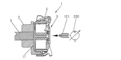
図20は、ノイズを低減するための空気噴出を用いる、本発明に係るロータリーフックのさらなる1つの実施形態を示す概略図である。 FIG. 20 is a schematic diagram illustrating a further embodiment of a rotary hook according to the present invention that uses air jets to reduce noise.
図21は、ノイズを低減するための空気噴出を用いる、本発明に係るロータリーフックの他のさらなる1つの実施形態を示す概略図である。 FIG. 21 is a schematic diagram illustrating another further embodiment of the rotary hook according to the present invention, which uses an air jet to reduce noise.
添付の図面では、該当する構成要素は参照番号で一致するように示してある。 In the accompanying drawings, the corresponding components are shown to be matched by reference numerals.
図1は、当該分野において公知となっている、水平回転軸を有するロータリーフックの分解図を概略的に示す図である。同図において、本説明に関連のある構成要素のみに参照番号を付してある。 FIG. 1 is a diagram schematically showing an exploded view of a rotary hook having a horizontal rotating shaft, which is known in the art. In the figure, only constituent elements relevant to the present description are provided with reference numerals.
フック体2は、ここに示す例では、シャフト(図面の簡便さのために省略)を受け入れるのに適切な中央穴17(図2)を有する円筒状キャビティー11を備えており、フック1は、上記シャフトの動きに連動する。異なる実施形態では、上記シャフトはフック1と一体である(図3および図10を参照)。
In the example shown here, the
バスケット6は、その外側表面に形成されるリブ14によって押さえつけられる円筒状キャビティー11の内側において自由に回転する。
The
C型の案内溝は10、互いに平行な2つの平面(そのうち1つは部分的にジブ110によって形成されている)と、1つの平面に垂直な円筒状表面によって定められている、フック体2の円筒状キャビティー11の内壁に形成されている。バスケット6のリブ14が、わずかな遊び(約0.01mmから約0.1mm)に係合することによって、円筒状キャビティー11におけるバスケット6の軸方向かつ放射状の移動を防止する。
The C-shaped
ボビン4は、バスケット6または、場合によるとバスケット6の内側に設けられているボビンケース5によって保持される。
The
図2は、回転軸を通過する面を通して組み上げた、図1のロータリーフック1の断面を概略的に示す図である。図2に示すのは、円筒状キャビティー11を備えるフック体2と、バスケット6のリブ14と、バスケット6のリブ14が係合するフック体の案内溝10と、バスケット6の底面壁15と円筒状キャビティー11の中央穴17である。底面壁15と中央穴17とは、シャフト(図面の簡便さのために省略)を収容することができ、該シャフトの動きはフック1に連動する。その一方で、異なる実施形態では、シャフトとフック1とは一体である(図3および図10を参照)。
FIG. 2 is a view schematically showing a cross section of the
本発明に係るロータリーフック1は、軸方向の圧力をバスケット6にかけ、バスケット6のリブ14を、フック体2の円筒状キャビティー11にある案内溝10を定める平面の1つに向けて押し付けるのに適した手段を備える。
The
バスケット6にかかる軸方向の圧力は、50グラム(0.49N)以下であることが好ましい。
The axial pressure applied to the
本発明に係るロータリーフック1の好ましい実施形態では、図3〜図16において概略的に示すが、バスケット6に軸方向の圧力を加える手段は、少なくとも1つの磁気要素を備える。この磁気要素は、
A)フック体2に固定され、バスケット6(金属であり、それゆえ強磁性である)を引き付けることができ、以下の部材からなる。
A.1)図3に示すように、シャフト9が固定されているフック体2の円筒状キャビティー11の底面に設けられた盲点凹部24に組み込まれた円盤型磁石23、
A.2)フック体2の円筒状キャビティー11の底面に設けられた凹部26に組み込まれ、シャフト9が収容される中央穴17(図4)、もしくはロータリーフック1の異なる実施形態では、潤滑システム(例えば、図10に示される)の中央穴を閉じる円盤型磁石25、
A.3)フック体2の円筒状キャビティー11の底面において、フック体2の中央穴17を変形しないように設けられている円形凹部28に組み込まれており、フック体2の回転軸に中心を置くリング状磁石27(図5および図6)、または、
A.4)フック体2の円筒状キャビティー11の底面において、フック体2の中央穴17を変形しないように一定間隔に配置されている一連の盲点凹部30もしくは一連の貫通孔に組み込められ、フック体の回転軸に対して軸対称である一定の力を生じさせるのに適している一連の円筒状磁石29(図7)。
B)バスケット6に固定することが可能であり、バスケット6をフック体2またはシャフト9(金属であり、それゆえ強磁性である)に向けて引き付け、以下の部材からなる。
B.1)バスケット6の底面壁15に設けられた盲点凹部33に組み込まれており、バスケット6の軸上に位置する円盤型磁石32(図8)、
B.2)バスケット6の軸上に位置する磁石柱35であって、上記磁石柱35もしくはそれらの所望しない回転を防ぐためにボビン4にブレーキをかける役割をもつ磁石柱35(図9)、
B.3)バスケット6の軸上に位置する磁気抽出器36(バスケット6が外面を有する場合)であって、上記磁石抽出器36はまた、それ自身の所望しない回転を防ぐためにボビン4にブレーキをかける役割をもつ磁気抽出器36(図10)、
B.4)バスケット6の底面壁15に形成された円形凹部38に組み込まれており、バスケット6の軸上に位置する円形磁石37(図11、図12)、または、
B.5)バスケット6の底面壁15において一定間隔に配置された一連の盲点凹部41または一連の貫通孔に組み込まれる一連の円筒状磁石39であって、バスケット6の軸に対して対称である一定の力を生じさせることができ(図13)、また、それ自身の所望しない回転を防ぐためにボビン4にブレーキをかける役割をもつ円筒状磁石39。
C)シャフト9に固定されており、上記シャフトの頂点に備えられ、フック体2の円筒状キャビティー11の表面に位置する円盤型磁石31。または、該表面に対してわずかに沈むように構成され、バスケット6を引き付ける円盤型磁石31(図14)。
D)本縫いミシンに含まれるバスケット6の近くまたはボビンケースの近くに組み入れられ、以下の部材からなる。
D.1)ミシンに含まれるバスケット6またはボビンケース5を引き付ける磁石42(図15)、または、
D.2)ミシンに含まれるバスケット6またはボビンケース5に取り付けられており、バスケット6を第1磁石43からはじく第2磁石44と相互に作用する、第2磁石44と同じ極性を有する第1磁石43(図16)、
本発明に係るロータリーフックの他の実施形態では、図17〜図19に概略的に示すように、バスケット6に軸方向の圧力を加えるのに適切な手段は、バスケット6の底面壁15とフック体2の円筒状キャビティー11との間を減圧する。
In a preferred embodiment of the
A) It is fixed to the
A. 1) As shown in FIG. 3, a disc-shaped
A. 2) A central hole 17 (FIG. 4) which is incorporated in a
A. 3) In the bottom surface of the
A. 4) On the bottom surface of the
B) It can be fixed to the
B. 1) A disc-shaped magnet 32 (FIG. 8) which is incorporated in a blind spot recess 33 provided in the
B. 2) A
B. 3) A
B. 4) A circular magnet 37 (FIGS. 11 and 12) which is incorporated in a
B. 5) A series of blind-
C) A disc-shaped magnet 31 that is fixed to the
D) The sewing machine is assembled near the
D. 1) Magnet 42 (FIG. 15) that attracts
D. 2) A
In another embodiment of the rotary hook according to the present invention, as schematically shown in FIGS. 17-19, suitable means for applying axial pressure to the
この「真空」効果によって、バスケット6はフック体2にはりつく。この効果は以下の手段によって得られる。
The
シャフト9の端部に設けられ、フック体2の円筒状キャビティー11と連結し、シャフト9に形成された軸穴9’によって真空ポンプ20と接続されているノズル21(図17)、または、
フック体2の中央穴17またはシャフト9の端部に設けられ、円筒状キャビティー11から空気を抜くための中央穴17を通してフック体2の円筒状キャビティー11と連結するファン16(図18および図19)。
A nozzle 21 (FIG. 17) provided at an end of the
A
ファン16によって抜かれた空気は、シャフト9の軸穴9’を通って(図18)、またはフック体2の中央穴17とフック体2の外側表面18とを接続する放射穴19を通って排出され、これにより遠心性の効果も得られる(図19)。
The air extracted by the
「真空」効果を向上するために、円筒状キャビティー11の側面に通常存在し、フック体2の重量を低減することによって、バランスをとる開口部を省略することができる。
In order to improve the “vacuum” effect, it is usually present on the side of the
本発明に係るロータリーフック1のさらなる実施形態では、図20および図21に概略的に示されるが、バスケット6に軸方向の圧力を加えるのに適切な手段は、バスケット6に対して軸方向の圧縮空気の噴出を、バスケット6上またはボビンケース5上に搬送することに適している。この搬送は以下の手段によって行われる。
In a further embodiment of the
コンプレッサー200に接続されており、圧縮空気の噴出をバスケット6上における軸方向(図20)に送るノズル121、または、
フック体2の円筒状キャビティー11と連結するシャフト9の端部に設けられ、シャフト9(図21)に設けられた軸穴9’によってコンプレッサー200に接続されるノズル221。
A
A
本発明は先に説明し、添付の図面に示す特定の実施形態に限定されないが、当業者が行える範囲内での細部における多くの変形は行ってもよく、該変形も添付の請求項に示す発明の範囲を逸脱することのないように行ってもよいことは明らかである。 The present invention is not limited to the specific embodiments described above and shown in the accompanying drawings, but many variations in detail can be made within the scope of those skilled in the art, which are also set forth in the appended claims. Obviously, the present invention may be carried out without departing from the scope of the invention.
〔符号の説明〕
1 ロータリーフック
2 フック体
4 ボビン
5 ボビンケース
6 バスケット
9 シャフト
10 案内溝
11 円筒状キャビティー
14 リブ
15 底面壁
16 ファン
17 中央穴
18 フック体の外側表面
19 放射穴
20 真空ポンプ
21 ノズル
23 円盤型磁石
24 盲点凹部
25 円盤型磁石
26 凹部
27 リング状磁石
28 円形凹部
29 円筒状磁石
30 盲点凹部
31 円盤型磁石
32 円盤型磁石
33 盲点凹部
35 磁石柱
36 磁石抽出器
37 円形磁石
38 円形凹部
39 円筒状磁石
41 盲点凹部
42 磁石
43 第1磁石
44 第2磁石
110 ジブ
121 ノズル
200 コンプレッサー
221 ノズル
[Explanation of symbols]
DESCRIPTION OF
Claims (6)
上記ロータリーフック(1)は、
上記2つの互いに平行な平面のうち1つを部分的に形成する上記フック体(2)に固定されたジブ(110)と、
上記フック体(2)の回転軸に対して軸対称である一定の力を生じさせる、少なくとも1つの磁気要素(23;25;27;29;32;35;36;37;39;31)と、を備え、
上記遊びを起因とする上記バスケットの振動によって引き起こされる当該ロータリーフック(1)のノイズを低減するために、上記フック体(2)の上記C型案内溝(10)を定める上記平面の1つに対して、上記バスケット(6)の上記リブ(14)を押し付けるように、上記少なくとも1つの磁気要素(23;25;27;29;32;35;36;37;39;31)は、上記バスケット(6)に軸方向の圧力を加えることを特徴とするロータリーフック(1)。 A rotary hook (1) for a lockstitch sewing machine comprising at least a hook body (2) having a cylindrical cavity (11) and a basket (or bobbin case holder) (6). 6) is an outer surface of the basket (6) engaged with a C-shaped guide groove (10) provided on the inner wall of the cylindrical cavity (11) of the hook body (2) with play. The hook body (2) freely rotates inside the cylindrical cavity (11) within a range limited by the rib (14) provided on the basket, and the basket ( In order to prevent movement in the axial and radial directions of 6), the range is defined by two parallel planes and a cylindrical surface perpendicular to the two planes. The hook body (2) is connected to the shaft (9) supporting the movement,
The rotary hook (1)
A jib (110) secured to the hook body (2) partially forming one of the two parallel planes;
At least one magnetic element (23; 25; 27; 29; 32; 35; 36; 37; 39; 31) that produces a constant force that is axisymmetric with respect to the axis of rotation of the hook body (2); With
To reduce the noise of the rotary hook (1) caused by the vibration of the basket due to the play, the one of the planes defining the C-shaped guide groove (10) of the hook body (2) The at least one magnetic element (23; 25; 27; 29; 32; 35; 36; 37; 39; 31) is pressed against the basket (6) against the rib (14). A rotary hook (1) characterized by applying axial pressure to (6 ).
上記フック体(2)の上記円筒状キャビティー(11)の底面に設けられた凹部(24)に組み込まれた円盤型磁石(23)、 A disc-shaped magnet (23) incorporated in a recess (24) provided on the bottom surface of the cylindrical cavity (11) of the hook body (2);
上記フック体(2)の上記円筒状キャビティー(11)の底面に設けられた凹部(26)に、上記シャフト(9)を収容する中央穴(17)もしくは潤滑システムの中央穴を閉じるように組み込まれている円盤型磁石(25)、 The central hole (17) for accommodating the shaft (9) or the central hole of the lubrication system is closed in the recess (26) provided on the bottom surface of the cylindrical cavity (11) of the hook body (2). Built-in disk magnet (25),
上記フック体(2)の上記円筒状キャビティー(11)の底面に設けられた円形凹部(28)に組み込まれており、上記フック体(2)の回転軸に中心を置くリング型磁石(27)、または、 A ring-type magnet (27) which is incorporated in a circular recess (28) provided on the bottom surface of the cylindrical cavity (11) of the hook body (2) and is centered on the rotation axis of the hook body (2). ) Or
上記フック体(2)の上記円筒状キャビティー(11)の底面において一定間隔に配置されている複数の凹部(30)もしくは貫通孔に組み込まれた複数の円筒状磁石(29)からなることを特徴とする請求項1に記載のロータリーフック(1)。 The hook body (2) comprises a plurality of concave portions (30) arranged at regular intervals on the bottom surface of the cylindrical cavity (11) or a plurality of cylindrical magnets (29) incorporated in through holes. Rotary hook (1) according to claim 1, characterized in that
上記バスケット(6)の底面壁(15)に設けられた凹部(33)に組み込まれており、上記バスケット(6)の軸上に位置する円盤型磁石(32)、 A disc-shaped magnet (32) which is incorporated in a recess (33) provided in the bottom wall (15) of the basket (6) and is located on the axis of the basket (6);
上記バスケット(6)の軸上に位置する磁石柱(35)であって、それ自身の所望しない回転を防止するために、ボビン(4)に適切なブレーキをかける磁石柱(35)、 A magnet column (35) located on the axis of the basket (6), which applies an appropriate brake to the bobbin (4) in order to prevent its own undesired rotation;
上記バスケット(6)の軸上に位置する磁気抽出器(36)であって、それ自身における所望しない回転を防止するために、上記ボビン(4)に適切なブレーキをかける磁気抽出器(36)、 Magnetic extractor (36) located on the axis of the basket (6), which applies an appropriate brake to the bobbin (4) to prevent undesired rotation in itself. ,
上記バスケット(6)の上記底面壁(15)に形成された円形凹部(38)に設けられており、上記バスケット(6)の軸上に位置するリング型磁石(37)、または、 A ring-shaped magnet (37) provided on a circular recess (38) formed in the bottom wall (15) of the basket (6) and positioned on the axis of the basket (6), or
上記バスケット(6)の上記底面壁(15)において一定間隔に配置された複数の凹部または貫通孔(41)に設けられており、上記バスケット(6)の軸に対して対称である一定の力を生じさせる複数の円筒状磁石(39)であって、それ自身の所望しない回転を防止するために、上記ボビン(4)に適切なブレーキをかける円筒状磁石(39)からなることを特徴とする請求項2に記載のロータリーフック(1)。 A constant force that is provided in a plurality of recesses or through-holes (41) arranged at regular intervals on the bottom wall (15) of the basket (6) and is symmetrical with respect to the axis of the basket (6). A plurality of cylindrical magnets (39), each of which comprises a cylindrical magnet (39) that applies an appropriate brake to the bobbin (4) in order to prevent its own undesired rotation. The rotary hook (1) according to claim 2.
上記バスケット(6)またはそれに含まれるボビンケース(5)を引き付ける、上記本縫いミシンに設けられた第1の磁石(42)、または、 A first magnet (42) provided on the lockstitch sewing machine that attracts the basket (6) or a bobbin case (5) included therein; or
上記バスケット(6)またはそれに含まれる上記ボビンケース(5)に取り付けられた第2の磁石(44)と相互に作用する、上記本縫いミシンに設けられた第1の磁石(43)からなり、上記第2の磁石(44)は、上記第1の磁石(43)に対して同じ極性を有する本縫いミシン。 The basket (6) or the first magnet (43) provided in the lockstitch sewing machine that interacts with the second magnet (44) attached to the basket (6) or the bobbin case (5) included therein, The second sewing machine (44) is a lockstitch sewing machine having the same polarity as that of the first magnet (43).
Applications Claiming Priority (2)
| Application Number | Priority Date | Filing Date | Title |
|---|---|---|---|
| ITMI2008A002105 | 2008-11-25 | ||
| ITMI2008A002105A IT1392162B1 (en) | 2008-11-25 | 2008-11-25 | ROTARY CROCHET FOR SEWING MACHINE WITH POINTED TAPES INCLUDING MEANS TO REDUCE ITS NOISE |
Publications (2)
| Publication Number | Publication Date |
|---|---|
| JP2010155070A JP2010155070A (en) | 2010-07-15 |
| JP5525245B2 true JP5525245B2 (en) | 2014-06-18 |
Family
ID=41130009
Family Applications (1)
| Application Number | Title | Priority Date | Filing Date |
|---|---|---|---|
| JP2009266233A Active JP5525245B2 (en) | 2008-11-25 | 2009-11-24 | Rotary hook for lockstitch machine with means to reduce noise |
Country Status (5)
| Country | Link |
|---|---|
| US (1) | US8342110B2 (en) |
| EP (1) | EP2189565B1 (en) |
| JP (1) | JP5525245B2 (en) |
| CN (1) | CN101736535B (en) |
| IT (1) | IT1392162B1 (en) |
Families Citing this family (8)
| Publication number | Priority date | Publication date | Assignee | Title |
|---|---|---|---|---|
| ITMI20130324A1 (en) | 2013-03-04 | 2014-09-05 | Cm Cerliani S R L | ROTARY CROCHET WITH CAPSULE FOR SEWING MACHINE WITH A TAPPED STITCH INCLUDING MEANS TO REDUCE GAMES BETWEEN CAPSULE AND BASKET AND REDUCE NOISE |
| JP6359867B2 (en) * | 2014-04-24 | 2018-07-18 | 蛇の目ミシン工業株式会社 | Sewing machine horizontal rotary hook |
| JP6452309B2 (en) * | 2014-04-24 | 2019-01-16 | 蛇の目ミシン工業株式会社 | Sewing machine horizontal rotary hook |
| DE102015111580A1 (en) * | 2014-08-05 | 2016-02-11 | Cm Cerliani S.R.L. | Gripper for a lockstitch sewing machine with stable tension of the bobbin thread |
| US9797077B2 (en) * | 2015-02-09 | 2017-10-24 | Cm Cerliani S.R.L. | Hook for lockstitch sewing machine comprising a bobbin case with a slide composed of multiple components |
| GB201803199D0 (en) * | 2018-02-27 | 2018-04-11 | Michel Van De Wiele | A tufting machine |
| USD953010S1 (en) * | 2018-12-04 | 2022-05-31 | Cm Cerliani S.R.L. | Bobbin case |
| CN110735250A (en) * | 2019-11-26 | 2020-01-31 | 浙江华洋缝制有限公司 | kinds of shuttle core sleeve and its making method |
Family Cites Families (13)
| Publication number | Priority date | Publication date | Assignee | Title |
|---|---|---|---|---|
| US32809A (en) | 1861-07-09 | Improvement in machinery for plowing and tilling land | ||
| IT998910B (en) * | 1972-10-24 | 1976-02-20 | Manta Sa | ROTATING ONE FOR SEWING MACHINES |
| JPS6117736Y2 (en) * | 1980-09-26 | 1986-05-30 | ||
| JPS58216090A (en) * | 1982-06-10 | 1983-12-15 | 蛇の目ミシン工業株式会社 | Apparatus for controlling tension of lower yarn of sewing machine |
| JPS6043997B2 (en) | 1983-09-06 | 1985-10-01 | 株式会社廣瀬製作所 | Full rotation hook of lockstitch sewing machine |
| JPH0632730B2 (en) * | 1984-08-31 | 1994-05-02 | 蛇の目ミシン工業株式会社 | Thread tension setting sewing machine |
| JPS61268292A (en) * | 1985-05-23 | 1986-11-27 | 蛇の目ミシン工業株式会社 | Needle and bobbin thread regulator of sewing machine |
| US5152236A (en) * | 1990-12-13 | 1992-10-06 | Hirose Manufacturing Company, Limited | Bobbin holding structure |
| JPH07144081A (en) * | 1993-11-24 | 1995-06-06 | Brother Ind Ltd | Sewing machine |
| US6257512B1 (en) * | 1998-12-16 | 2001-07-10 | Fil-Tec, Inc. | Magnetized pre-wound sideless bobbins |
| JP3420548B2 (en) * | 2000-03-15 | 2003-06-23 | 株式会社廣瀬製作所 | Vertical full rotation kettle |
| DE10028231B4 (en) * | 2000-05-27 | 2004-11-04 | Philipp Moll | Device on sewing or embroidery machines for changing the bobbin for the hook thread |
| JP4450198B2 (en) * | 2004-09-28 | 2010-04-14 | ブラザー工業株式会社 | Horizontal rotary hook |
-
2008
- 2008-11-25 IT ITMI2008A002105A patent/IT1392162B1/en active
-
2009
- 2009-11-20 EP EP09176587.5A patent/EP2189565B1/en active Active
- 2009-11-24 JP JP2009266233A patent/JP5525245B2/en active Active
- 2009-11-25 CN CN2009102265951A patent/CN101736535B/en active Active
- 2009-11-25 US US12/625,616 patent/US8342110B2/en active Active
Also Published As
| Publication number | Publication date |
|---|---|
| EP2189565A3 (en) | 2010-08-18 |
| ITMI20082105A1 (en) | 2010-05-26 |
| US20100126399A1 (en) | 2010-05-27 |
| JP2010155070A (en) | 2010-07-15 |
| EP2189565B1 (en) | 2014-01-01 |
| CN101736535B (en) | 2013-11-06 |
| IT1392162B1 (en) | 2012-02-22 |
| CN101736535A (en) | 2010-06-16 |
| EP2189565A2 (en) | 2010-05-26 |
| US8342110B2 (en) | 2013-01-01 |
Similar Documents
| Publication | Publication Date | Title |
|---|---|---|
| JP5525245B2 (en) | Rotary hook for lockstitch machine with means to reduce noise | |
| CA2862620C (en) | Top | |
| US7552453B2 (en) | Disk driving apparatus | |
| US7561704B2 (en) | Structure of speaker | |
| JP4450198B2 (en) | Horizontal rotary hook | |
| JP2017108714A (en) | Fishing spinning reel | |
| US7612477B2 (en) | Electromagnetic brake device for small-sized motor | |
| US9850608B2 (en) | Rotary hook with bobbin case for a lockstitch sewing machine including means to reduce the plays between bobbin case and basket and to reduce the noise thereof | |
| JP2006506256A (en) | Belt and tread drum | |
| US20060283322A1 (en) | Hermetic compressor | |
| JP2013052755A (en) | Luggage caster | |
| KR101489050B1 (en) | Apparatus for fixing metal wheel of top | |
| CN206969234U (en) | Fixing piece | |
| JP7014776B2 (en) | Grinding wheel with vibration damping support body | |
| JP2004278574A (en) | Lock ball device | |
| CN107380655A (en) | Fixing piece | |
| JP6776093B2 (en) | Centrifuge | |
| CN107558105B (en) | Pulsator washing machine | |
| AU2014101116A4 (en) | Brushless Motor | |
| US20200271109A1 (en) | Piston drive device | |
| JP2010148459A (en) | Spinning reel | |
| JP3054640U (en) | Nakagami on sewing machine | |
| JP2001224286A (en) | Double bearing type reel for fishing | |
| KR102118598B1 (en) | Clutch for compressor | |
| WO2018221281A1 (en) | Rocking plate type variable displacement compressor |
Legal Events
| Date | Code | Title | Description |
|---|---|---|---|
| A621 | Written request for application examination |
Free format text: JAPANESE INTERMEDIATE CODE: A621 Effective date: 20121122 |
|
| A977 | Report on retrieval |
Free format text: JAPANESE INTERMEDIATE CODE: A971007 Effective date: 20130805 |
|
| A131 | Notification of reasons for refusal |
Free format text: JAPANESE INTERMEDIATE CODE: A131 Effective date: 20130820 |
|
| A601 | Written request for extension of time |
Free format text: JAPANESE INTERMEDIATE CODE: A601 Effective date: 20131120 |
|
| A602 | Written permission of extension of time |
Free format text: JAPANESE INTERMEDIATE CODE: A602 Effective date: 20131125 |
|
| A521 | Request for written amendment filed |
Free format text: JAPANESE INTERMEDIATE CODE: A523 Effective date: 20131204 |
|
| TRDD | Decision of grant or rejection written | ||
| A01 | Written decision to grant a patent or to grant a registration (utility model) |
Free format text: JAPANESE INTERMEDIATE CODE: A01 Effective date: 20140325 |
|
| A61 | First payment of annual fees (during grant procedure) |
Free format text: JAPANESE INTERMEDIATE CODE: A61 Effective date: 20140411 |
|
| R150 | Certificate of patent or registration of utility model |
Ref document number: 5525245 Country of ref document: JP Free format text: JAPANESE INTERMEDIATE CODE: R150 |
|
| R250 | Receipt of annual fees |
Free format text: JAPANESE INTERMEDIATE CODE: R250 |
|
| R250 | Receipt of annual fees |
Free format text: JAPANESE INTERMEDIATE CODE: R250 |
|
| R250 | Receipt of annual fees |
Free format text: JAPANESE INTERMEDIATE CODE: R250 |
|
| R250 | Receipt of annual fees |
Free format text: JAPANESE INTERMEDIATE CODE: R250 |
|
| R250 | Receipt of annual fees |
Free format text: JAPANESE INTERMEDIATE CODE: R250 |
|
| R250 | Receipt of annual fees |
Free format text: JAPANESE INTERMEDIATE CODE: R250 |
|
| R250 | Receipt of annual fees |
Free format text: JAPANESE INTERMEDIATE CODE: R250 |
|
| R250 | Receipt of annual fees |
Free format text: JAPANESE INTERMEDIATE CODE: R250 |