EP1640490A1 - Horizontal rotary hook for sewing machine - Google Patents
Horizontal rotary hook for sewing machine Download PDFInfo
- Publication number
- EP1640490A1 EP1640490A1 EP05021067A EP05021067A EP1640490A1 EP 1640490 A1 EP1640490 A1 EP 1640490A1 EP 05021067 A EP05021067 A EP 05021067A EP 05021067 A EP05021067 A EP 05021067A EP 1640490 A1 EP1640490 A1 EP 1640490A1
- Authority
- EP
- European Patent Office
- Prior art keywords
- rotary hook
- bottom wall
- magnet piece
- yoke member
- sewing machine
- Prior art date
- Legal status (The legal status is an assumption and is not a legal conclusion. Google has not performed a legal analysis and makes no representation as to the accuracy of the status listed.)
- Withdrawn
Links
Images




Classifications
-
- D—TEXTILES; PAPER
- D05—SEWING; EMBROIDERING; TUFTING
- D05B—SEWING
- D05B57/00—Loop takers, e.g. loopers
- D05B57/08—Loop takers, e.g. loopers for lock-stitch sewing machines
- D05B57/10—Shuttles
- D05B57/20—Shuttles with bobbin casings held by magnetic forces
-
- D—TEXTILES; PAPER
- D05—SEWING; EMBROIDERING; TUFTING
- D05B—SEWING
- D05B57/00—Loop takers, e.g. loopers
- D05B57/08—Loop takers, e.g. loopers for lock-stitch sewing machines
- D05B57/10—Shuttles
- D05B57/14—Shuttles with rotary hooks
- D05B57/143—Vertical axis type
Definitions
- the present invention relates to a horizontal rotary hook of a sewing machine provided with an inner rotary hook and an outer rotary hook respectively made of synthetic resin wherein the inner rotary hook is pulled toward the outer rotary hook by the magnetic force of a thin plate-shaped magnet piece.
- horizontal rotary hooks offering simple and handy bobbin exchange have been widely used.
- Such types of horizontal rotary hooks are provided with an outer rotary hook formed with a race surface and an inner rotary hook housing a bobbin retained rotatably in relative to the race surface.
- the outer rotary hook is rotated in a predetermined direction by a sewing machine motor or the like.
- the inner rotary hook is made of a synthetic resin to achieve reduction of weight and manufacturing cost.
- the outer rotary hook is also made of a synthetic resin.
- various types of horizontal rotary hooks using magnets have been proposed to prevent the inner rotary hook from floating up with respect to the outer rotary hook during sewing work.
- JP-Y1-1989-54784 discloses a horizontal rotary hook having an outer rotary hook embedded with a thin ring-shaped magnet in the inner bottom surface thereof as well as having an inner rotary hook with the outer bottom surface almost entirely covered with a metal material which is attracted by the magnet.
- the purpose of the present invention is to provide a horizontal rotary hook of a sewing machine capable of obtaining sufficient attraction between an inner rotary hook and an outer rotary hook while restraining the size increase of the entire construction.
- the horizontal rotary hook of the present invention includes an inner rotary hook made of synthetic resin and housing a bobbin; an outer rotary hook rotationally driven to a predetermined direction and housing the inner rotary hook and an adsorption plate made of a magnetic material provided on one of the outer surface of the bottom wall of the inner rotary hook and the inner surface of the bottom wall of the outer rotary hook.
- the horizontal rotary hook of the present invention further includes a thin plate-shaped magnet piece to pull the adsorption plate provided on the other of the outer surface of the bottom wall of the inner rotary hook and the inner surface of the bottom wall of the outer rotary hook; and a yoke member made of a magnetic material housing the magnet piece.
- the present invention provides a horizontal rotary hook of a sewing machine comprising an inner rotary hook made of synthetic resin and housing a bobbin and an outer rotary hook made of synthetic resin and housing the inner rotary hook and rotated in a predetermined direction, characterized by an adsorption plate made of a magnetic material and provided on one of an outer surface of a bottom wall of the inner rotary hook and an inner surface of a bottom wall of the outer rotary hook, a magnet piece formed as a thin plate and provided in the other of the outer surface of the bottom wall of the inner rotary hook and the inner surface of the bottom wall of the outer rotary hook, and a yoke member made of a magnetic material and housing the magnet piece integrally formed with a bottom wall contacting the magnet piece and a surrounding wall surrounding an outer circumferential side of the magnet piece, the yoke member being provided on the other of the outer surface of the bottom wall of the inner rotary hook and the inner surface of the bottom wall of the outer rotary hook.
- the yoke member is integrally formed with a bottom wall contacting the magnet piece and a surrounding wall surrounding the outer circumference of the magnet piece.
- the floating of the inner rotary hook from the outer rotary hook is prevented by pulling the inner rotary hook toward the outer rotary hook by a magnetic attraction between the adsorption plate made of and the thin plate-shaped magnet piece.
- the magnet piece is provided in a housed state in the yoke member integrally formed with a bottom wall and a surrounding wall, a magnetic path is formed extending from the top surface of the magnet piece to the bottom surface of the magnet piece via the adsorption plate, the surrounding wall, the bottom wall of the yoke member and the bottom surface of the magnet piece.
- the magnetic attraction between the magnet piece and the adsorption plate can be increased, thereby increasing the magnetic force to pull the inner rotary hook toward the outer rotary hook.
- the adsorption plate in the outer surface of the bottom wall of the inner rotary hook and provide the magnet piece and the yoke member in the inner surface of the bottom wall of the outer rotary hook. Also, by locking the yoke member with a collar plate of the outer rotary hook shaft, the magnet piece and the yoke member can be mounted on the outer rotary hook without using an adhesive agent or a adhesive tape.
- the sewing machine body 51 as shown in FIG. 1A is integrally formed with an arm 53 above the bed 52.
- a needle bar 55 having a sewing needle 54 is provided on a distal end of the arm 53 and is vertically moved by a driving mechanism not shown.
- a metal needle plate 56 is provided on the upper surface of the bed 52 opposing the needle bar 55.
- a bobbin accommodation hole 57 having an oblong opening is formed in front of the aforementioned needle hole 56a and the long holes 56b.
- the bobbin accommodation hole 57 is slidably opened/closed in a front/rear direction by a transparent sliding lid 58 (refer to FIG. 1A) which is inserted into two sliding grooves 57a located in the left and right portions of the bobbin accommodation hole 57 respectively. Only one of the sliding grooves 57a is shown in FIG. 1B.
- a cloth feed mechanism (not shown) to drive the feed dog in synchronization with the vertical movement of the needle bar 55 is provided.
- a horizontal full rotary hook 1 according to the present invention is also provided inside the bed 52. The hook 1 is located in the lower portion of the accommodation hole 57 of the needle plate 56 and supplies a bobbin thread 59 as well as executing the sewing work in co-operation with the sewing needle 54.
- this horizontal full rotary hook 1 includes an outer rotary hook 2 (refer to FIG. 2) having a tip member 4 which rotates in a horizontal direction in synchronization with the vertical movement of the needle bar 55 and an inner rotary hook 3 (refer to FIG. 2) provided in the outer rotary hook 2 in an unrotatable state with respect to the bed 52.
- a bobbin 6 wound with the bobbin thread 59 is removably housed inside the inner rotary hook 3.
- a plastic work clamp 60 is provided in the area of the accommodation hole 57.
- An opening is provided on the work clamp 60 for removing the bobbin 6 and also, though not shown, a rotation restrictor to prevent the rotation of the inner rotary hook 3 is provided on the bottom surface of the work clamp 60.
- the horizontal full rotary hook 1 will be described in detail with reference to FIGS. 2 to 7.
- the inner rotary hook 3 will be described.
- the overall inner rotary hook 3 is formed as an approximate circular container with a shallow bottom made of synthetic resin material (for example a polyimide) .
- the inside portion of the inner rotary hook 3 will be referred to as a bobbin housing 3b to house the bobbin 6 and in the central portion of a bottom wall 3e, a shaft 3f to which the bobbin 6 is inserted rotatably is provided.
- a rotation restrictor 3c is provided on the near side of the outer circumferential portion of the inner rotary hook 3 to prevent the rotation of the inner rotary hook 3.
- a notch 3a allowing the needle 54 to pass therethrough is provided in the far side of the outer circumferential portion of the inner rotary hook 3.
- a protruding thread guide 3d is formed on one end of the notch 3a.
- a tension generator (not shown) is provided to apply tension to the bobbin thread 59.
- the tension generator comprises an arc-shaped thread tension plate and an arc-shaped thread tension spring both laid one upon the other.
- a circular adsorption plate 8 made of a magnetic material such as a steel plate is provided on an outer surface (or an underside) of the bottom wall 3e so as to be coplanar with the underside.
- the adsorption plate 8 is adhered to the inner rotary hook 3 by a two-sided adhesive tape, for example.
- the outer rotary hook 2 is constructed as follows. That is, as shown in FIGS. 5 and 6, the outer rotary hook 2 is made of a synthetic resin material, for example, a polyimide resin formed as a cylindrical container with an opened upper surface and in more detail, is integrally formed with a disc-shaped bottom wall 2c and an outer circumferential wall 2a rising up from the outer circumference. This outer rotary hook 2 is to have a slightly larger diameter than the inner rotary hook 3.
- a part of the outer circumferential wall 2a of the outer rotary hook 2 is removably mounted with the tip member 4 in a separate, synthetic resin body.
- an annular race surface 2b having a lowered inner circumference is formed on an upper edge of the outer circumferential wall 2a so as to extend over the entire circumference.
- the bottom surface of the outer circumferential end of the inner rotary hook 3 is formed to be slidably placed on the race surface 2b.
- the inner rotary hook 3 is housed in the outer rotary hook 2 with the bottom wall 3e in a floated state.
- the outer rotary hook 2 is integrally formed with a drive shaft 5 extending downward from the central portion of the bottom (bottom wall 2c) of the outer rotary hook 2.
- the drive shaft 5 is in the form of a tube having vertically penetrating shaft slot 2d therethrough as well as having a gear portion in the form of a warm gear on the outer circumference.
- the outer rotary hook 2 is mounted rotatably to a fixing portion 18 of a sewing machine frame by an outer rotary hook shaft 16.
- This outer rotary hook shaft 16 is integrally formed with a collar plate 16b on the upper end of a shaft body 16a which is inserted into the shaft slot 2d.
- the outer rotary hook shaft 16 inserted into the shaft slot 2d rotatably supports the outer rotary hook 2 by fixing the lower end of the outer rotary hook shaft 16 to the fixing portion 18 of the sewing machine frame (the bottom of the bed 52) by a screw 19.
- a rotary hook drive mechanism not shown has a drive gear in mesh engagement with a gear portion of the drive shaft 5, so that the outer rotary hook 2 is rotated via the drive gear and the drive shaft 5.
- a thin plate-shaped magnet piece 12 that pulls the adsorption plate 8 is provided on an inner surface (upper surface) of the bottom wall 2c of the outer rotary hook 2 and housed in a yoke member 10.
- the magnet piece 12 is formed into the shape of a ring and has a notch 12a in the central portion. As shown in FIGS. 5 and 7, the notch 12a is set to have a larger diameter than the collar plate 16b of the outer rotary hook shaft 16. Also, this magnet piece 12 has different magnetic poles in the top and bottom sides and as shown in FIG. 7, the upper surface is magnetized as a north (N) pole and the lower surface is magnetized as a south (S) pole.
- N north
- S south
- the yoke member 10 is made of a magnetic material, for example, a thin steel plate and is formed as a circular container with a shallow bottom integrally formed with a bottom wall 10b contacting the lower surface of the magnet piece 12 (magnet piece 12 is placed thereon) and a surrounding wall 10c surrounding the outer circumferential side of the magnet piece 12 in the same height as the magnet piece 12.
- the bottom wall 10b of the yoke member 10 has an insertion hole 10a formed in the center thereof. The diameter dimension of the insertion hole 10a is larger than the outer diameter of the shaft body 16a of the outer rotary hook shaft 16 and smaller than the outer diameter of the collar plate 16b.
- locating ribs are provided on the inner surface of the bottom wall 2c of the outer rotary hook 2 so as to surround the outer circumference of the yoke member 10. That is, the ribs are composed of a plurality of, for example, 6 rib pieces 2e approximately equally spaced apart, altogether arranged in an annular form.
- protrusions 10d locked by the ribs to restrict the rotation with respect to the outer rotary hook 2 are provided on the outer circumference of the yoke member 10.
- the protrusions 10d in more detail are formed such that the portion opposing the surrounding wall 10c is partially protruded outward. The lock between the protrusions 10d and the rib pieces 2e prevents the rotation of the yoke member 10 with respect to the outer rotary hook 2.
- the yoke member 10 of such construction is, as shown in FIGS. 5 to 7, placed on the bottom wall 2c (within the rib pieces 2e) where the yoke member 10 is locked unmovably to the upper direction, that is, to the axial direction of the outer rotary hook shaft 16 by pressing the surrounding portions of the insertion hole 10a with the collar plate 16b formed on the outer rotary hook shaft 16.
- the magnet piece 12 is fitted into the yoke member 10 and fixed by the magnetic adsorption between the yoke member 10.
- a wave washer 14 which is a ring-shaped thrust bearing plate is provided in between the collar plate 16b and the yoke member 10.
- a flat washer 18a is provided in between the outer rotary hook 2 and the fixing portion 18 of the sewing machine frame.
- the yoke member 10 is placed on the inner surface of the bottom wall 2c of the outer rotary hook 2 while being located to a predetermined location by 6 rib pieces 2e arranged in annular form. At this point, as shown in FIG. 3, the protrusions 10d are arranged in the spaces between the rib pieces 2e.
- the shaft body 16a of the outer rotary hook shaft 16 is inserted from above into the shaft slot 2d of the outer rotary hook 2 with the wave washer 14 placed on the upper side of the bottom wall 10b of the yoke member 10.
- the flat washer 18a is placed in between the outer rotary hook 2 and the fixing portion 18 of the sewing machine frame and the lower end of the outer rotary hook shaft 16 inserted into the shaft slot 2d of the outer rotary hook 2 is fixed to the fixing portion 18 by the screw 19. After that, the ring-shaped magnet piece 12 is fitted into the yoke member 10.
- the inner rotary hook 3 is housed in the outer rotary hook 2 by adjusting the placement of the outer circumference of the inner rotary hook 3 on the race surface 2b of the outer rotary hook 2.
- the assembly of the horizontal rotary hook 1 is completed (refer to FIG. 5).
- the adsorption plate 8 on the outer bottom surface of the inner rotary hook 3 and the yoke member 10 housing the magnet piece 12 are arranged in an opposing manner, slightly spaced apart from one another.
- the adsorption plate 8 is provided on the outer surface of the bottom wall 3e of the inner rotary hook 3 and the magnet piece 12 is housed in the yoke member 10 in the inner surface of the bottom wall 2c of the outer rotary hook 2, the magnetic attraction of the inner rotary hook 3 with respect to the outer rotary hook 2 can be increased.
- a magnetic path M is defined between the magnet piece 12 and the adsorption plate 8, extending from the top surface (N pole) of the magnet piece 12 to the bottom surface (S pole) via the adsorption plate 8, surrounding wall 10c and the bottom wall 10b of the yoke member 10. Therefore, the.magnetic lines of force are concentrated amongst the foregoing and the adsorption of the magnet piece 12 with respect to the adsorption plate 8 by the magnetic power of the magnet piece 12, that is, the pull of the magnet piece 12 with respect to the inner rotary hook 3 is increased. Hence, the floating of the inner rotary hook 3 from the outer rotary hook 2 is effectively prevented.
- the size or the thickness of the magnet piece 12 can be relatively reduced.
- the yoke member 10 since the yoke member 10 is made of a thin plate covering the surroundings and the bottom surface of the magnet piece 12, the yoke member 10 and the magnet piece 12 taken together will not lead to much size increase. Consequently, the size increase of the magnet piece 12 and the outer rotary hook 2 can be prevented.
- the ribs 2e are integrally formed on the bottom wall 2c of the outer rotary hook 2 to locate the yoke member 10, moreover, the rotation of the yoke member 10 is prevented by the ribs 2e and furthermore, the yoke member 10 is locked to prevent an upward dislocation by the collar plate 16b of the outer rotary hook shaft 16.
- the assembly of the yoke member 10 and the magnet piece 12 is simplified without requiring any extra part for assembly or rotation restriction purposes, thereby providing simplified construction.
- the dislocation of the yoke member 10 or magnet piece 12 can be prevented.
- the wave washer 14 is provided in between the collar plate 16b and the yoke member 10, wear-out and rattling of the slide contacting portion of the collar plate 16b and the yoke member 10 can be prevented and a smooth rotation of the outer rotary hook 2 (yoke member 10) with respect to the outer rotary hook shaft 16 is enabled.
- the present invention is not limited to the horizontal full rotary hook 1 wherein a outer rotary hook 2 housing a inner rotary hook 3 is rotationally driven to the predetermined direction, but may also be applied to horizontal rotary hooks in general such as a shuttle hook.
- six ribs 2e are provided in the inner surface of the bottom wall 2c of the outer rotary hook 2 as well as providing the protrusions 10d to the outer circumference of the yoke member 10.
- annular ribs formed with protrusions protruding towards the inner circumference can be provided in the inner surface of the bottom wall 2c of the outer rotary hook 2 as well as providing notches on the surrounding wall 10c of the yoke member 10 so that the protrusions can be locked to the notches.
- the adsorption plate 8 is provided on the outer surface of the bottom wall 3e of the inner rotary hook 3 and the magnet piece 12 and the yoke member 10 is provided in the inner surface of the bottom wall 2c of the outer rotary hook 2.
- the magnet piece 12 and the yoke member 10 can be provided on the outer surface of the bottom wall 3e of the inner rotary hook 3 and the adsorption plate 8 can be provided on the inner surface of the bottom wall 2c of the outer rotary hook 2.
- the yoke member 10 and the magnet piece 12 housed therein can be formed in a shape other than the ring shape. That is, the contours of the yoke member 10 and the magnet piece 12 can be formed in a quadrilateral, a triangle or a polygon in flat view.
- the thrust bearing plate may be integrally formed in the yoke member 10 and the wave washer 14 may be omitted, for further reduction in the number of parts.
- the assembly procedure of the horizontal full rotary hook 1 should not be limited to the above-described.
- the magnet piece 12 may be fitted into the yoke member 10 in advance.
- the above-described assembly procedure may be changed and reduced to practice accordingly.
Landscapes
- Engineering & Computer Science (AREA)
- Textile Engineering (AREA)
- Sewing Machines And Sewing (AREA)
Abstract
Description
- The present invention relates to a horizontal rotary hook of a sewing machine provided with an inner rotary hook and an outer rotary hook respectively made of synthetic resin wherein the inner rotary hook is pulled toward the outer rotary hook by the magnetic force of a thin plate-shaped magnet piece.
- Conventionally, horizontal rotary hooks offering simple and handy bobbin exchange have been widely used. Such types of horizontal rotary hooks are provided with an outer rotary hook formed with a race surface and an inner rotary hook housing a bobbin retained rotatably in relative to the race surface. The outer rotary hook is rotated in a predetermined direction by a sewing machine motor or the like.
- The inner rotary hook is made of a synthetic resin to achieve reduction of weight and manufacturing cost. Also, in recent years, the outer rotary hook is also made of a synthetic resin. Such being the case, various types of horizontal rotary hooks using magnets have been proposed to prevent the inner rotary hook from floating up with respect to the outer rotary hook during sewing work. For example, JP-Y1-1989-54784 discloses a horizontal rotary hook having an outer rotary hook embedded with a thin ring-shaped magnet in the inner bottom surface thereof as well as having an inner rotary hook with the outer bottom surface almost entirely covered with a metal material which is attracted by the magnet.
- However, a simple provision of a magnet in the outer rotary hook made of synthetic resin would limit the magnet to a relatively small size, consequently providing insufficient attraction with respect to the inner rotary hook. As a result, the floating of the inner rotary hook is not prevented effectively. Such being the case, mounting of a large type magnet generating strong magnetic force on the outer rotary hook is a possible alternative; however, such countermeasures give rise to problems such as cost and size increase of the horizontal rotary hook. In the outer rotary hook made of synthetic resin, the magnet needs to be fixed to the bottom surface of the outer rotary hook by an adhesive agent or a two-sided adhesive tape. However, this will result in complicated assembly work and furthermore, since the magnet is of small size, consequently having small adhesion area incapable of providing enough adhesion, problems have occurred where the magnet fell off while in use.
- The purpose of the present invention is to provide a horizontal rotary hook of a sewing machine capable of obtaining sufficient attraction between an inner rotary hook and an outer rotary hook while restraining the size increase of the entire construction.
- The horizontal rotary hook of the present invention includes an inner rotary hook made of synthetic resin and housing a bobbin; an outer rotary hook rotationally driven to a predetermined direction and housing the inner rotary hook and an adsorption plate made of a magnetic material provided on one of the outer surface of the bottom wall of the inner rotary hook and the inner surface of the bottom wall of the outer rotary hook. The horizontal rotary hook of the present invention further includes a thin plate-shaped magnet piece to pull the adsorption plate provided on the other of the outer surface of the bottom wall of the inner rotary hook and the inner surface of the bottom wall of the outer rotary hook; and a yoke member made of a magnetic material housing the magnet piece.
- The present invention provides a horizontal rotary hook of a sewing machine comprising an inner rotary hook made of synthetic resin and housing a bobbin and an outer rotary hook made of synthetic resin and housing the inner rotary hook and rotated in a predetermined direction, characterized by an adsorption plate made of a magnetic material and provided on one of an outer surface of a bottom wall of the inner rotary hook and an inner surface of a bottom wall of the outer rotary hook, a magnet piece formed as a thin plate and provided in the other of the outer surface of the bottom wall of the inner rotary hook and the inner surface of the bottom wall of the outer rotary hook, and a yoke member made of a magnetic material and housing the magnet piece integrally formed with a bottom wall contacting the magnet piece and a surrounding wall surrounding an outer circumferential side of the magnet piece, the yoke member being provided on the other of the outer surface of the bottom wall of the inner rotary hook and the inner surface of the bottom wall of the outer rotary hook.
- The yoke member is integrally formed with a bottom wall contacting the magnet piece and a surrounding wall surrounding the outer circumference of the magnet piece. In the present invention, the floating of the inner rotary hook from the outer rotary hook is prevented by pulling the inner rotary hook toward the outer rotary hook by a magnetic attraction between the adsorption plate made of and the thin plate-shaped magnet piece. At this point, since the magnet piece is provided in a housed state in the yoke member integrally formed with a bottom wall and a surrounding wall, a magnetic path is formed extending from the top surface of the magnet piece to the bottom surface of the magnet piece via the adsorption plate, the surrounding wall, the bottom wall of the yoke member and the bottom surface of the magnet piece. Hence, even if the magnet piece is relatively small, the magnetic attraction between the magnet piece and the adsorption plate can be increased, thereby increasing the magnetic force to pull the inner rotary hook toward the outer rotary hook.
- In the present invention, considering the mounting space and ease of assembly, it is desirable to provide the adsorption plate in the outer surface of the bottom wall of the inner rotary hook and provide the magnet piece and the yoke member in the inner surface of the bottom wall of the outer rotary hook. Also, by locking the yoke member with a collar plate of the outer rotary hook shaft, the magnet piece and the yoke member can be mounted on the outer rotary hook without using an adhesive agent or a adhesive tape.
- The invention will be described, merely by way of example, with reference to the accompanying drawings, in which,
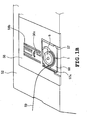
- FIG. 1A is a perspective overview of a sewing machine showing an embodiment of the present invention;
- FIG. 1B is an enlarged perspective view of a needle plate;
- FIG. 2 is a plan view of a horizontal full rotary hook;
- FIG. 3 is a plan view of an outer rotary hook;
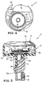
- FIG. 4 is a plan view of an inner rotary hook;
- FIG. 5 is a vertical sectional side view of the horizontal full rotary hook;
- FIG. 6 is an exploded vertical sectional side view of each part constructing the outer rotary hook; and
- FIG. 7 is an enlarged vertical sectional side view of the magnet piece.
- An embodiment of the present invention is described hereinafter with reference to the drawings. The present embodiment is an example applying the present invention to a horizontal full rotary hook rotatably driven continuously in one direction.
- First, an overall construction of a sewing machine according to the present embodiment is described with reference to FIGS. 1A and 1B.
- The
sewing machine body 51 as shown in FIG. 1A is integrally formed with anarm 53 above thebed 52. Aneedle bar 55 having asewing needle 54 is provided on a distal end of thearm 53 and is vertically moved by a driving mechanism not shown. On the other hand, as also shown in FIG. 1B, ametal needle plate 56 is provided on the upper surface of thebed 52 opposing theneedle bar 55. On theneedle plate 56 are formed aneedle hole 56a through which theneedle bar 55 penetrates and plurality oflong holes 56b for operation of a feed dog not shown. Also, abobbin accommodation hole 57 having an oblong opening is formed in front of theaforementioned needle hole 56a and thelong holes 56b. Thebobbin accommodation hole 57 is slidably opened/closed in a front/rear direction by a transparent sliding lid 58 (refer to FIG. 1A) which is inserted into two slidinggrooves 57a located in the left and right portions of thebobbin accommodation hole 57 respectively. Only one of thesliding grooves 57a is shown in FIG. 1B. - Inside the
bed 52 is provided a cloth feed mechanism (not shown) to drive the feed dog in synchronization with the vertical movement of theneedle bar 55 is provided. A horizontal fullrotary hook 1 according to the present invention is also provided inside thebed 52. Thehook 1 is located in the lower portion of theaccommodation hole 57 of theneedle plate 56 and supplies abobbin thread 59 as well as executing the sewing work in co-operation with thesewing needle 54. - As described in detail hereinafter, this horizontal full
rotary hook 1 includes an outer rotary hook 2 (refer to FIG. 2) having atip member 4 which rotates in a horizontal direction in synchronization with the vertical movement of theneedle bar 55 and an inner rotary hook 3 (refer to FIG. 2) provided in the outerrotary hook 2 in an unrotatable state with respect to thebed 52. As shown in FIG. 1B, abobbin 6 wound with thebobbin thread 59 is removably housed inside the innerrotary hook 3. Also, on the bottom surface of theneedle plate 56, aplastic work clamp 60 is provided in the area of theaccommodation hole 57. An opening is provided on thework clamp 60 for removing thebobbin 6 and also, though not shown, a rotation restrictor to prevent the rotation of the innerrotary hook 3 is provided on the bottom surface of thework clamp 60. - Hence, owning to a counterclockwise rotation of the outer
rotary hook 2 about the outer circumference of the innerrotary hook 3 in synchronization with the vertical movement of theneedle bar 55, a loop of needle thread not shown formed under theneedle hole 56a by thesewing needle 54 is captured by thetip member 4. Then, the loop is pulled around the exterior of the innerrotary hook 3 and forms a stitch with thebobbin thread 59. - Now, the horizontal full
rotary hook 1 will be described in detail with reference to FIGS. 2 to 7. First, the innerrotary hook 3 will be described. As shown in FIGS. 4 and 5, the overall innerrotary hook 3 is formed as an approximate circular container with a shallow bottom made of synthetic resin material (for example a polyimide) . The inside portion of the innerrotary hook 3 will be referred to as abobbin housing 3b to house thebobbin 6 and in the central portion of abottom wall 3e, ashaft 3f to which thebobbin 6 is inserted rotatably is provided. - As shown in FIG. 4, a
rotation restrictor 3c is provided on the near side of the outer circumferential portion of the innerrotary hook 3 to prevent the rotation of the innerrotary hook 3. Also, anotch 3a allowing theneedle 54 to pass therethrough is provided in the far side of the outer circumferential portion of the innerrotary hook 3. A protrudingthread guide 3d is formed on one end of thenotch 3a. Furthermore, on the inner wall of thebobbin housing 3b, a tension generator (not shown) is provided to apply tension to thebobbin thread 59. The tension generator comprises an arc-shaped thread tension plate and an arc-shaped thread tension spring both laid one upon the other. - In the present embodiment, as shown in FIG. 5, a
circular adsorption plate 8 made of a magnetic material such as a steel plate is provided on an outer surface (or an underside) of thebottom wall 3e so as to be coplanar with the underside. In this case, theadsorption plate 8 is adhered to the innerrotary hook 3 by a two-sided adhesive tape, for example. - As opposed to this, the outer
rotary hook 2 is constructed as follows. That is, as shown in FIGS. 5 and 6, the outerrotary hook 2 is made of a synthetic resin material, for example, a polyimide resin formed as a cylindrical container with an opened upper surface and in more detail, is integrally formed with a disc-shapedbottom wall 2c and an outercircumferential wall 2a rising up from the outer circumference. This outerrotary hook 2 is to have a slightly larger diameter than the innerrotary hook 3. - As shown in FIG. 3, a part of the outer
circumferential wall 2a of the outerrotary hook 2 is removably mounted with thetip member 4 in a separate, synthetic resin body. Also, anannular race surface 2b having a lowered inner circumference is formed on an upper edge of the outercircumferential wall 2a so as to extend over the entire circumference. As shown in FIG. 2, the bottom surface of the outer circumferential end of the innerrotary hook 3 is formed to be slidably placed on therace surface 2b. Hence, as shown in FIG. 5, the innerrotary hook 3 is housed in the outerrotary hook 2 with thebottom wall 3e in a floated state. - Furthermore, the outer
rotary hook 2 is integrally formed with adrive shaft 5 extending downward from the central portion of the bottom (bottom wall 2c) of the outerrotary hook 2. Thedrive shaft 5 is in the form of a tube having vertically penetratingshaft slot 2d therethrough as well as having a gear portion in the form of a warm gear on the outer circumference. As shown in FIGS. 5 and 6, the outerrotary hook 2 is mounted rotatably to a fixingportion 18 of a sewing machine frame by an outerrotary hook shaft 16. - This outer
rotary hook shaft 16 is integrally formed with acollar plate 16b on the upper end of ashaft body 16a which is inserted into theshaft slot 2d. As shown in FIG. 5, the outerrotary hook shaft 16 inserted into theshaft slot 2d rotatably supports the outerrotary hook 2 by fixing the lower end of the outerrotary hook shaft 16 to the fixingportion 18 of the sewing machine frame (the bottom of the bed 52) by ascrew 19. Also, a rotary hook drive mechanism not shown has a drive gear in mesh engagement with a gear portion of thedrive shaft 5, so that the outerrotary hook 2 is rotated via the drive gear and thedrive shaft 5. - A thin plate-shaped
magnet piece 12 that pulls theadsorption plate 8 is provided on an inner surface (upper surface) of thebottom wall 2c of the outerrotary hook 2 and housed in ayoke member 10. - The
magnet piece 12 is formed into the shape of a ring and has anotch 12a in the central portion. As shown in FIGS. 5 and 7, thenotch 12a is set to have a larger diameter than thecollar plate 16b of the outerrotary hook shaft 16. Also, thismagnet piece 12 has different magnetic poles in the top and bottom sides and as shown in FIG. 7, the upper surface is magnetized as a north (N) pole and the lower surface is magnetized as a south (S) pole. - On the other hand, the
yoke member 10 is made of a magnetic material, for example, a thin steel plate and is formed as a circular container with a shallow bottom integrally formed with abottom wall 10b contacting the lower surface of the magnet piece 12 (magnet piece 12 is placed thereon) and a surroundingwall 10c surrounding the outer circumferential side of themagnet piece 12 in the same height as themagnet piece 12. Also, as shown in FIG. 5, thebottom wall 10b of theyoke member 10 has aninsertion hole 10a formed in the center thereof. The diameter dimension of theinsertion hole 10a is larger than the outer diameter of theshaft body 16a of the outerrotary hook shaft 16 and smaller than the outer diameter of thecollar plate 16b. - As shown in FIGS. 3 and 6, locating ribs are provided on the inner surface of the
bottom wall 2c of the outerrotary hook 2 so as to surround the outer circumference of theyoke member 10. That is, the ribs are composed of a plurality of, for example, 6rib pieces 2e approximately equally spaced apart, altogether arranged in an annular form. - As opposed to this, on the outer circumference of the
yoke member 10,protrusions 10d locked by the ribs to restrict the rotation with respect to the outerrotary hook 2 are provided. Theprotrusions 10d in more detail are formed such that the portion opposing the surroundingwall 10c is partially protruded outward. The lock between theprotrusions 10d and therib pieces 2e prevents the rotation of theyoke member 10 with respect to the outerrotary hook 2. - The
yoke member 10 of such construction is, as shown in FIGS. 5 to 7, placed on thebottom wall 2c (within therib pieces 2e) where theyoke member 10 is locked unmovably to the upper direction, that is, to the axial direction of the outerrotary hook shaft 16 by pressing the surrounding portions of theinsertion hole 10a with thecollar plate 16b formed on the outerrotary hook shaft 16. Themagnet piece 12 is fitted into theyoke member 10 and fixed by the magnetic adsorption between theyoke member 10. - At this point, a
wave washer 14 which is a ring-shaped thrust bearing plate is provided in between thecollar plate 16b and theyoke member 10. Aflat washer 18a is provided in between the outerrotary hook 2 and the fixingportion 18 of the sewing machine frame. - Next, an assembly procedure of the horizontal full
rotary hook 1 will be described with reference to FIG. 6. - First, the
yoke member 10 is placed on the inner surface of thebottom wall 2c of the outerrotary hook 2 while being located to a predetermined location by 6rib pieces 2e arranged in annular form. At this point, as shown in FIG. 3, theprotrusions 10d are arranged in the spaces between therib pieces 2e. Next, theshaft body 16a of the outerrotary hook shaft 16 is inserted from above into theshaft slot 2d of the outerrotary hook 2 with thewave washer 14 placed on the upper side of thebottom wall 10b of theyoke member 10. Then, theflat washer 18a is placed in between the outerrotary hook 2 and the fixingportion 18 of the sewing machine frame and the lower end of the outerrotary hook shaft 16 inserted into theshaft slot 2d of the outerrotary hook 2 is fixed to the fixingportion 18 by thescrew 19. After that, the ring-shapedmagnet piece 12 is fitted into theyoke member 10. - Then, the inner
rotary hook 3 is housed in the outerrotary hook 2 by adjusting the placement of the outer circumference of the innerrotary hook 3 on therace surface 2b of the outerrotary hook 2. Thus, the assembly of the horizontalrotary hook 1 is completed (refer to FIG. 5). At this point, as shown in FIGS. 5 and 7, theadsorption plate 8 on the outer bottom surface of the innerrotary hook 3 and theyoke member 10 housing themagnet piece 12 are arranged in an opposing manner, slightly spaced apart from one another. - Next, the operation and effect of the horizontal full
rotary hook 1 having the above construction will be described. - In the horizontal full
rotary hook 1 having the above construction, since theadsorption plate 8 is provided on the outer surface of thebottom wall 3e of the innerrotary hook 3 and themagnet piece 12 is housed in theyoke member 10 in the inner surface of thebottom wall 2c of the outerrotary hook 2, the magnetic attraction of the innerrotary hook 3 with respect to the outerrotary hook 2 can be increased. - More specifically, as shown in FIG. 7, a magnetic path M is defined between the
magnet piece 12 and theadsorption plate 8, extending from the top surface (N pole) of themagnet piece 12 to the bottom surface (S pole) via theadsorption plate 8, surroundingwall 10c and thebottom wall 10b of theyoke member 10. Therefore, the.magnetic lines of force are concentrated amongst the foregoing and the adsorption of themagnet piece 12 with respect to theadsorption plate 8 by the magnetic power of themagnet piece 12, that is, the pull of themagnet piece 12 with respect to the innerrotary hook 3 is increased. Hence, the floating of the innerrotary hook 3 from the outerrotary hook 2 is effectively prevented. - Also, by achieving the increase of magnetic attraction, the size or the thickness of the
magnet piece 12 can be relatively reduced. As for theyoke member 10, since theyoke member 10 is made of a thin plate covering the surroundings and the bottom surface of themagnet piece 12, theyoke member 10 and themagnet piece 12 taken together will not lead to much size increase. Consequently, the size increase of themagnet piece 12 and the outerrotary hook 2 can be prevented. - In the present embodiment, the
ribs 2e are integrally formed on thebottom wall 2c of the outerrotary hook 2 to locate theyoke member 10, moreover, the rotation of theyoke member 10 is prevented by theribs 2e and furthermore, theyoke member 10 is locked to prevent an upward dislocation by thecollar plate 16b of the outerrotary hook shaft 16. Hence, the assembly of theyoke member 10 and themagnet piece 12 is simplified without requiring any extra part for assembly or rotation restriction purposes, thereby providing simplified construction. As opposed to adhering the magnet by an adhesive agent or an adhesive tape, the dislocation of theyoke member 10 ormagnet piece 12 can be prevented. - Also, since the
wave washer 14 is provided in between thecollar plate 16b and theyoke member 10, wear-out and rattling of the slide contacting portion of thecollar plate 16b and theyoke member 10 can be prevented and a smooth rotation of the outer rotary hook 2 (yoke member 10) with respect to the outerrotary hook shaft 16 is enabled. - Next, transformations of the aforementioned embodiment are described.
- The present invention is not limited to the horizontal full
rotary hook 1 wherein a outerrotary hook 2 housing a innerrotary hook 3 is rotationally driven to the predetermined direction, but may also be applied to horizontal rotary hooks in general such as a shuttle hook. - Also, in the above embodiment, six
ribs 2e are provided in the inner surface of thebottom wall 2c of the outerrotary hook 2 as well as providing theprotrusions 10d to the outer circumference of theyoke member 10. However, it is not limited to such arrangement. That is, annular ribs formed with protrusions protruding towards the inner circumference can be provided in the inner surface of thebottom wall 2c of the outerrotary hook 2 as well as providing notches on the surroundingwall 10c of theyoke member 10 so that the protrusions can be locked to the notches. - Furthermore, in the above embodiment, the
adsorption plate 8 is provided on the outer surface of thebottom wall 3e of the innerrotary hook 3 and themagnet piece 12 and theyoke member 10 is provided in the inner surface of thebottom wall 2c of the outerrotary hook 2. However, themagnet piece 12 and theyoke member 10 can be provided on the outer surface of thebottom wall 3e of the innerrotary hook 3 and theadsorption plate 8 can be provided on the inner surface of thebottom wall 2c of the outerrotary hook 2. - Furthermore, the
yoke member 10 and themagnet piece 12 housed therein can be formed in a shape other than the ring shape. That is, the contours of theyoke member 10 and themagnet piece 12 can be formed in a quadrilateral, a triangle or a polygon in flat view. - Also, the thrust bearing plate may be integrally formed in the
yoke member 10 and thewave washer 14 may be omitted, for further reduction in the number of parts. - The assembly procedure of the horizontal full
rotary hook 1 should not be limited to the above-described. For example, themagnet piece 12 may be fitted into theyoke member 10 in advance. Thus, the above-described assembly procedure may be changed and reduced to practice accordingly.
Claims (6)
- A horizontal rotary hook of a sewing machine comprising an inner rotary hook (3) made of synthetic resin and housing a bobbin (6) and an outer rotary hook (2) made of synthetic resin and housing the inner rotary hook (3) and rotated in a predetermined direction, characterized by:an adsorption plate (8) made of a magnetic material and provided on one of an outer surface of a bottom wall (3e) of the inner rotary hook (3) and an inner surface of a bottom wall (2c) of the outer rotary hook (2);a magnet piece (12) formed as a thin plate and provided in the other of the outer surface of the bottom wall (3e) of the inner rotary hook (3) and the inner surface of the bottom wall (2c) of the outer rotary hook (2); anda yoke member (10) made of a magnetic material and housing the magnet piece (12) integrally formed with a bottom wall (10b) contacting the magnet piece (12) and a surrounding wall (10c) surrounding an outer circumferential side of the magnet piece (12), the yoke member (10) being provided on the other of the outer surface of the bottom wall (3e) of the inner rotary hook (3) and the inner surface of the bottom wall (2c) of the outer rotary hook (2).
- The horizontal rotary hook of a sewing machine according to claim 1, characterized in that the adsorption plate (8) is provided on the outer surface of the bottom wall (3e) of the inner rotary hook (3) and the magnet piece (12) and the yoke member (10) are provided on the inner surface of the bottom wall (2c) of the outer rotary hook (2).
- The horizontal rotary hook of a sewing machine according to claim 1 or 2, characterized in that the outer rotary hook (2) is rotatably supported by an outer rotary hook shaft (16) fixed to a sewing machine frame while the yoke member (10) is locked by a collar plate (16b) formed on the outer rotary hook shaft (16) such that the yoke member (10) is unmovable in an axial direction of the outer rotary hook shaft (16) fixed to the sewing machine frame.
- The horizontal rotary hook of a sewing machine according to one of claims 1 to 3, further characterized by ribs provided on the inner surface of the bottom wall (2c) of the outer rotary hook (2) for locating the yoke member (10).
- The horizontal rotary hook of a sewing machine according to claim 4, further characterized by protrusions (10d) provided on the outer circumference of the yoke member (10) for preventing rotation with respect to the outer rotary hook (2) by being locked by the ribs.
- The horizontal rotary hook of a sewing machine according to claim 3 or 4, characterized in that the magnet piece (12) is formed in a ring shape and the collar plate (16b) is arranged on an inner circumferential portion of the magnet piece (12), the horizontal rotary hook being further characterized by a ring-shaped thrust bearing plate (14) provided in between the collar plate (16b) and the yoke member (10).
Applications Claiming Priority (1)
| Application Number | Priority Date | Filing Date | Title |
|---|---|---|---|
| JP2004281375A JP4450198B2 (en) | 2004-09-28 | 2004-09-28 | Horizontal rotary hook |
Publications (1)
| Publication Number | Publication Date |
|---|---|
| EP1640490A1 true EP1640490A1 (en) | 2006-03-29 |
Family
ID=35427630
Family Applications (1)
| Application Number | Title | Priority Date | Filing Date |
|---|---|---|---|
| EP05021067A Withdrawn EP1640490A1 (en) | 2004-09-28 | 2005-09-27 | Horizontal rotary hook for sewing machine |
Country Status (4)
| Country | Link |
|---|---|
| US (1) | US7171914B2 (en) |
| EP (1) | EP1640490A1 (en) |
| JP (1) | JP4450198B2 (en) |
| CN (1) | CN1755001B (en) |
Cited By (2)
| Publication number | Priority date | Publication date | Assignee | Title |
|---|---|---|---|---|
| ITMI20082105A1 (en) * | 2008-11-25 | 2010-05-26 | Daniele Cerliani | ROTARY CROCHET FOR SEWING MACHINE WITH POINTED TAPES INCLUDING MEANS TO REDUCE ITS NOISE |
| DE102014102756A1 (en) | 2013-03-04 | 2014-09-04 | Cm Cerliani S.R.L. | Noise-reduced rotary gripper with bobbin case for a lockstitch sewing machine |
Families Citing this family (12)
| Publication number | Priority date | Publication date | Assignee | Title |
|---|---|---|---|---|
| JP5465419B2 (en) * | 2008-11-13 | 2014-04-09 | 蛇の目ミシン工業株式会社 | Sewing machine horizontal rotary hook |
| CN102433694B (en) * | 2011-09-15 | 2013-03-13 | 张金福 | Transmission mechanism of three-needle lockstitch sewing machine |
| KR101780853B1 (en) * | 2011-09-26 | 2017-09-21 | 엔에스디 가부시끼가이샤 | Sewing machine |
| JP6452309B2 (en) * | 2014-04-24 | 2019-01-16 | 蛇の目ミシン工業株式会社 | Sewing machine horizontal rotary hook |
| JP6359867B2 (en) * | 2014-04-24 | 2018-07-18 | 蛇の目ミシン工業株式会社 | Sewing machine horizontal rotary hook |
| JP6389393B2 (en) * | 2014-08-05 | 2018-09-12 | 蛇の目ミシン工業株式会社 | sewing machine |
| JP6553912B2 (en) * | 2015-03-30 | 2019-07-31 | 蛇の目ミシン工業株式会社 | The outer pot of the sewing machine |
| CN105862274B (en) * | 2016-05-19 | 2019-01-18 | 江门市冠京制衣有限公司 | The hanging shuttle of lateral magnetic force formula covers sewing device |
| JP7102226B2 (en) * | 2018-05-18 | 2022-07-19 | 株式会社ジャノメ | Needle plate attachment / detachment mechanism and sewing machine equipped with it |
| CN110735250A (en) * | 2019-11-26 | 2020-01-31 | 浙江华洋缝制有限公司 | A bobbin case and its manufacturing method |
| CN113564822B (en) * | 2021-09-23 | 2021-12-17 | 南通金梭精密机械有限公司 | Large thread capacity sewing machine rotating shuttle |
| CN115522332A (en) * | 2022-06-01 | 2022-12-27 | 东阳市太极精密制造有限公司 | Cooperating structure of rotary hook for reducing thread take-up resistance of rotary hook surface and manufacturing method thereof |
Citations (3)
| Publication number | Priority date | Publication date | Assignee | Title |
|---|---|---|---|---|
| JPS6454784A (en) | 1987-08-26 | 1989-03-02 | Matsushita Electric Industrial Co Ltd | Electrostrictive actuator |
| JPH07112088A (en) * | 1993-10-19 | 1995-05-02 | Hirose Mfg Co Ltd | Sewing machine bite |
| JPH0824461A (en) * | 1994-07-20 | 1996-01-30 | Janome Sewing Mach Co Ltd | Structure of horizontal hook of sewing machine |
Family Cites Families (20)
| Publication number | Priority date | Publication date | Assignee | Title |
|---|---|---|---|---|
| US2394369A (en) * | 1943-09-13 | 1946-02-05 | White Sewing Machine Corp | Rotary loop taker for sewing machines |
| US3347193A (en) * | 1965-07-30 | 1967-10-17 | Union Special Machine Co | Semi-dull finish bobbin case basket |
| CH479742A (en) * | 1968-02-08 | 1969-10-15 | Pfaff Ag G M | Winding device on sewing machines |
| JPS4934057U (en) * | 1972-06-29 | 1974-03-26 | ||
| JPS5343215B2 (en) * | 1972-08-19 | 1978-11-17 | ||
| JPS54168959U (en) * | 1978-05-15 | 1979-11-29 | ||
| JPS5754784Y2 (en) * | 1978-07-06 | 1982-11-26 | ||
| JPS6020991Y2 (en) * | 1979-06-08 | 1985-06-22 | 蛇の目ミシン工業株式会社 | Upper thread control device in horizontal hook |
| JPS6117736Y2 (en) * | 1980-09-26 | 1986-05-30 | ||
| JPS582415U (en) * | 1981-06-30 | 1983-01-08 | 日本アンテナ株式会社 | Fixing mechanism |
| JPS61176397A (en) * | 1985-01-30 | 1986-08-08 | 株式会社廣瀬製作所 | Rotary hook |
| JPH0517031Y2 (en) * | 1986-12-26 | 1993-05-07 | ||
| JPH04244190A (en) * | 1991-01-30 | 1992-09-01 | Brother Ind Ltd | Superposed seaming method with sewing machine and data processor therefor |
| TW425443B (en) * | 1996-05-16 | 2001-03-11 | Juki Kk | Bobbin case and bobbin thread bobbin of sewing machine |
| JPH11267008A (en) * | 1998-03-19 | 1999-10-05 | Fuji Planning:Kk | Coordinating Tassel |
| CN2330674Y (en) * | 1998-04-16 | 1999-07-28 | 高丁炎 | Sewing machine full rotary hook clamp |
| JP2001231676A (en) * | 2000-02-21 | 2001-08-28 | Lec Inc | Magnetic suspension |
| DE10028231B4 (en) * | 2000-05-27 | 2004-11-04 | Philipp Moll | Device on sewing or embroidery machines for changing the bobbin for the hook thread |
| JP4313552B2 (en) * | 2002-08-06 | 2009-08-12 | Juki株式会社 | Sewing machine inner pot |
| CN2576752Y (en) * | 2002-11-04 | 2003-10-01 | 陈曲波 | Novel thread-raking device of micro electric sewing machine |
-
2004
- 2004-09-28 JP JP2004281375A patent/JP4450198B2/en not_active Expired - Fee Related
-
2005
- 2005-09-21 US US11/230,522 patent/US7171914B2/en not_active Expired - Lifetime
- 2005-09-27 EP EP05021067A patent/EP1640490A1/en not_active Withdrawn
- 2005-09-27 CN CN2005101085008A patent/CN1755001B/en not_active Expired - Fee Related
Patent Citations (3)
| Publication number | Priority date | Publication date | Assignee | Title |
|---|---|---|---|---|
| JPS6454784A (en) | 1987-08-26 | 1989-03-02 | Matsushita Electric Industrial Co Ltd | Electrostrictive actuator |
| JPH07112088A (en) * | 1993-10-19 | 1995-05-02 | Hirose Mfg Co Ltd | Sewing machine bite |
| JPH0824461A (en) * | 1994-07-20 | 1996-01-30 | Janome Sewing Mach Co Ltd | Structure of horizontal hook of sewing machine |
Non-Patent Citations (2)
| Title |
|---|
| PATENT ABSTRACTS OF JAPAN vol. 1995, no. 08 29 September 1995 (1995-09-29) * |
| PATENT ABSTRACTS OF JAPAN vol. 1996, no. 05 31 May 1996 (1996-05-31) * |
Cited By (5)
| Publication number | Priority date | Publication date | Assignee | Title |
|---|---|---|---|---|
| ITMI20082105A1 (en) * | 2008-11-25 | 2010-05-26 | Daniele Cerliani | ROTARY CROCHET FOR SEWING MACHINE WITH POINTED TAPES INCLUDING MEANS TO REDUCE ITS NOISE |
| EP2189565A3 (en) * | 2008-11-25 | 2010-08-18 | Daniele Cerliani | Rotary hook for a lockstitch sewing machine, comprising means to reduce the noise thereof |
| US8342110B2 (en) | 2008-11-25 | 2013-01-01 | Daniele Cerliani | Rotary hook for a locksmith sewing machine, comprising means to reduce the noise thereof |
| DE102014102756A1 (en) | 2013-03-04 | 2014-09-04 | Cm Cerliani S.R.L. | Noise-reduced rotary gripper with bobbin case for a lockstitch sewing machine |
| US9850608B2 (en) | 2013-03-04 | 2017-12-26 | Cm Cerliani S.R.L. | Rotary hook with bobbin case for a lockstitch sewing machine including means to reduce the plays between bobbin case and basket and to reduce the noise thereof |
Also Published As
| Publication number | Publication date |
|---|---|
| US20060065175A1 (en) | 2006-03-30 |
| CN1755001B (en) | 2011-04-27 |
| JP2006094905A (en) | 2006-04-13 |
| US7171914B2 (en) | 2007-02-06 |
| CN1755001A (en) | 2006-04-05 |
| JP4450198B2 (en) | 2010-04-14 |
Similar Documents
| Publication | Publication Date | Title |
|---|---|---|
| US7171914B2 (en) | Horizontal rotary hook for sewing machine | |
| CN102459739B (en) | Bottom thread tension control device for sewing machine and sewing machine | |
| US8342110B2 (en) | Rotary hook for a locksmith sewing machine, comprising means to reduce the noise thereof | |
| US4284017A (en) | Rotary hook for sewing machine | |
| CN212346302U (en) | Cook machine with liftable machine head | |
| EP0031323B1 (en) | Rotary hook for sewing machine | |
| JP2006008349A (en) | Parts supply device | |
| CN105002673B (en) | The horizontal rotary hook of sewing machine | |
| US20170152618A1 (en) | Accessories box for a sewing machine | |
| SE543070C2 (en) | Fastening device for removably attaching an object, as well as a method for removably attaching an object | |
| CN222383031U (en) | Pot cover structure and cooking machine | |
| CN215701429U (en) | Coil spring tool for assembling coil spring in tape measure and coil spring assembling structure | |
| US9238883B2 (en) | Horizontal rotary hook of sewing machine | |
| JP4097837B2 (en) | Fabric tension frame for embroidery sewing machine | |
| JP2006141800A (en) | Sewing machine horizontal pot | |
| US7397155B2 (en) | Motor, drive unit and actuating device | |
| EP1705280B1 (en) | Safety cover for sewing machine | |
| CN116281033B (en) | Round Can Bone Finder | |
| JP2003324912A (en) | Winding machine and winding method | |
| JPS6040205Y2 (en) | Full-rotation hook of sewing machine | |
| JP2696846B2 (en) | Embroidery frame mounting device for sewing machine | |
| KR950006832Y1 (en) | Vtr reel table | |
| JPH0211008Y2 (en) | ||
| JPS61160404A (en) | Method and apparatus for meshing woven fabric | |
| JPS61228895A (en) | Inner hook safety apparatus of sewing machine using full rotation hook |
Legal Events
| Date | Code | Title | Description |
|---|---|---|---|
| PUAI | Public reference made under article 153(3) epc to a published international application that has entered the european phase |
Free format text: ORIGINAL CODE: 0009012 |
|
| AK | Designated contracting states |
Kind code of ref document: A1 Designated state(s): AT BE BG CH CY CZ DE DK EE ES FI FR GB GR HU IE IS IT LI LT LU LV MC NL PL PT RO SE SI SK TR |
|
| AX | Request for extension of the european patent |
Extension state: AL BA HR MK YU |
|
| 17P | Request for examination filed |
Effective date: 20060926 |
|
| AKX | Designation fees paid |
Designated state(s): AT BE BG CH CY CZ DE DK EE ES FI FR GB GR HU IE IS IT LI LT LU LV MC NL PL PT RO SE SI SK TR |
|
| STAA | Information on the status of an ep patent application or granted ep patent |
Free format text: STATUS: THE APPLICATION HAS BEEN WITHDRAWN |
|
| 18W | Application withdrawn |
Effective date: 20120503 |