EP0489980A1 - Bobbin holding structure - Google Patents
Bobbin holding structure Download PDFInfo
- Publication number
- EP0489980A1 EP0489980A1 EP90203282A EP90203282A EP0489980A1 EP 0489980 A1 EP0489980 A1 EP 0489980A1 EP 90203282 A EP90203282 A EP 90203282A EP 90203282 A EP90203282 A EP 90203282A EP 0489980 A1 EP0489980 A1 EP 0489980A1
- Authority
- EP
- European Patent Office
- Prior art keywords
- bobbin
- case holder
- bobbin case
- holding member
- thread
- Prior art date
- Legal status (The legal status is an assumption and is not a legal conclusion. Google has not performed a legal analysis and makes no representation as to the accuracy of the status listed.)
- Granted
Links
Images

Classifications
-
- D—TEXTILES; PAPER
- D05—SEWING; EMBROIDERING; TUFTING
- D05B—SEWING
- D05B57/00—Loop takers, e.g. loopers
- D05B57/08—Loop takers, e.g. loopers for lock-stitch sewing machines
- D05B57/10—Shuttles
- D05B57/20—Shuttles with bobbin casings held by magnetic forces
-
- D—TEXTILES; PAPER
- D05—SEWING; EMBROIDERING; TUFTING
- D05B—SEWING
- D05B57/00—Loop takers, e.g. loopers
- D05B57/08—Loop takers, e.g. loopers for lock-stitch sewing machines
- D05B57/10—Shuttles
- D05B57/14—Shuttles with rotary hooks
Definitions
- the present invention relates to a bobbin holding structure to house and hold a bobbin in a bobbin case holder.
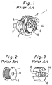
- Fig.1 is a perspective view of a typical prior art.
- Fig.2 is a perspective view of a bobbin 5.
- Fig.3 is a perspective view of a bobbin case 6 where the bobbin case 6 is shown partially cut away.
- a horizontal axis full rotary looptaker 1 provided in a lock stitch sewing machine has a rotating hook 3 where a rotary shaft 2 driven to rotate around a horizontal axis is fixed and a bobbin case holder 4 which is housed in the rotating hook 3, while the bobbin case holder 4 is provided with a bobbin case 6 which houses a bobbin 5.
- the bobbin case holder 4 is locked from rotating by a rotation stopper member 7, and when the rotary shaft 2 is driven to rotate, the rotating hook 3 rotates around the rotary axis while the bobbin case holder 4 remains stationary.
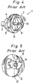
- Fig.4 is a perspective view of the horizontal axis full rotary looptaker 1 with the bobbin 5 and the bobbin case 6 removed therefrom.
- Fig.5 is a partially enlarged perspective view of the bobbin case 6.
- a stud 9 is provided vertically toward the opening on the bottom 8 of the bobbin case holder 4.
- a hollow shaft 10 of straight cylindrical shape is formed in the bobbin case 6.
- the hollow shaft 10 is inserted through a central hole 11 of the bobbin 5, and the bobbin 5 is housed in the bobbin case 6.
- the bobbin case 6 which houses the bobbin 5 is housed in the bobbin case holder 4 with the stud 9 inserted through the hollow shaft 10.
- An object of the invention is to provide a bobbin holding mechanism which enables it possible to easily attach and detach the bobbin in and from the bobbin case holder, and is capable of securely holding the bobbin in the bobbin case holder in a simple structure.
- the invention provides a bobbin holding mechanism where a bobbin holding member which attracts the bobbin to a bobbin case holder which houses the bobbin is mounted freely detachably.
- the bobbin holding member has a bobbin thread tensioning function.
- the bobbin thread tensioning function is achieved by a bobbin thread tensioner spring attached to the bobbin holding member.
- the bobbin holding member is provided which attracts the bobbin to the bobbin case holder which houses the bobbin.
- This constitution enables it to hold the bobbin securely within the bobbin case holder without allowing the bobbin to come off the bobbin case holder during sewing operation.
- the bobbin holding member is installed detachably in the bobbin case holder, the bobbin can be replaced easily and the efficiency of sewing operation can be improved.
- the bobbin holding member is installed in the bobbin case holder freely detachably, the bobbin can be easily taken out of the bobbin case holder. This enables to replace the bobbin quickly and easily, resulting in improved work efficiency.
- the bobbin holding mechanism of the invention can be implemented in a rotating hook of the prior art, making it possible to embody the invention widely in relation to existing sewing machines.
- the invention provides a bobbin holding mechanism comprising; a body installed along diameter of the bobbin case holder at an end face of the bobbin case holder made of a ferromagnetic material at the open end side of the bobbin case holder, and has a key slot formed at both ends in the longitudinal direction to accommodate the end face to fit therein, a shaft provided vertically at the center of the body in the longitudinal direction, of which tip extends to near the bottom of the bobbin case holder under the condition that the body is installed in the bobbin case holder, a bobbin thread tensioner spring of which base end is attached to the body and a bobbin thread guide slot to pass the bobbin thread is formed at a free end thereof, the free end making elastic contact with a side face of the body on the open side, a screw member provided on the bobbin thread tensioner spring which displaces the bobbin thread tensioner spring in a direction to approach to or go away from the body, to change the pressure against the side face of the free end, and
- the body under the condition that the bobbin holding member is installed in the bobbin case holder, the body is disposed in the direction of diameter of the bobbin case holder and the free end of the bobbin case holder fits in the key slot, thereby preventing displacement in the direction of diameter and enabling to position the body with respect to the bobbin case holder.
- tip of the shaft extends to near the bottom of the bobbin case holder, and the attraction piece provided at the tip thereof magnetically adheres to the bottom, to retain the bobbin in the bobbin case holder under this condition.
- This constitution makes it possible to change the bobbin easily and quickly, minimize the time taken to change the bobbin and improve the efficiency of sewing work.
- the body is equipped with the bobbin thread tensioner spring, the bobbin thread lead from the bobbin which is retained in the bobbin case holder can be properly tensioned, thereby enabling to form stitches of good quality without allowing slack in the thread.
- the bobbin housed in the bobbin case holder can be securely retained in the bobbin case holder by the bobbin holding member without allowing to come of the bobbin case holder. Because the bobbin holding member is installed in the bobbin case holder freely detachably, the bobbin can be easily removed from the bobbin case holder. This enables to replace the bobbin quickly improving the work efficiency.
- the bobbin holding mechanism of the invention is simpler in it constitution than in the case of the bobbin cases of the prior art and therefore provides for better productivity, enabling to manufacture at a lower cost.
- the bobbin holding mechanism of the invention enables to replace only the bobbin case holder unlike the rotating hooks of the prior art, and therefore can be applied widely in relation to the rotating hooks installed in the existing sewing machines.
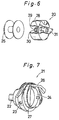
- Fig.6 is a perspective view of the bobbin holding member 20 illustrative of an embodiment of the invention
- Fig.7 is a perspective view of the horizontal axis full rotary looptaker 21 which is equipped with the bobbin holding member 20.
- the bobbin holding member 20 is shown partially cut away.
- the horizontal axis full rotary looptaker 21 installed in a lock stitch sewing machine is provided with a rotating hook 23 with a rotary shaft 22 fixed thereto which is driven to rotate around a horizontal rotary axis and a bobbin case holder 24 which is made of a ferromagnetic material such as iron and is housed in the rotating hook 23, and the bobbin holding member 20 with the bobbin 25 housed therein is installed in the bobbin case holder 24.
- the bobbin case holder 24 is prevented from rotating by a rotation stopper 26 and, under this condition, the rotating hook 23 is driven to rotate around the rotary axis thereof.
- the bottom 27 of the bobbin case holder 24 is flat because it is not necessary to install the stud 9 (Refer to Fig.4) described in the prior art.
- the bobbin holding member 20 has a cylindrically shaped shaft 28 which extends along the center axis 11 thereof. Formed at the tip of the shaft 28 is a recess 29 with an attraction piece 30 made of a magnetic material such as a permanent magnet fixed therein.
- an attraction piece 30 made of a magnetic material such as a permanent magnet fixed therein.
- installation of a cylindrical attraction piece in a hollow shaft 10 of the conventional bobbin case 6 makes it possible to use the conventional bobbin case holder 4, enabling to embody the invention widely in relation to existing rotating hooks.
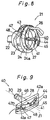
- Fig.8 is a perspective view of the bobbin holding member 40 installed in the horizontal axis full rotary looptaker 21 of the second embodiment of the invention.
- Fig.9 is an enlarged perspective view of the bobbin holding member 40.
- Fig.10 is a partially enlarged perspective view of the bobbin thread tensioner spring 43. Parts which correspond to those of the embodiment mentioned above are assigned the same reference numbers.
- the bobbin holding member 40 of the embodiment includes the body 41 which is installed at the end face 24a of the bobbin case holder 24 on the open end side along the direction of the diameter thereof, and a shaft 28 which is vertically disposed at the center of the body 41 in the longitudinal direction.
- the body 41 has fitting slots 42a, 42b at both ends thereof, and the fitting slots 42a, 42b accommodate the end face 24a of the bobbin case holder 24 to enable to install the bobbin holding member 40 in the bobbin case holder so that the axis of the shaft 28 agrees with the center axis of the bobbin case holder.
- Installed on the body 41 is the bobbin thread tensioner spring 43 of curved plate shape with the base end sections thereof fixed with screws 44.
- Freely passing through near the center of the bobbin thread tensioner spring 43 in the longitudinal direction is an adjust screw 45 which is screwed in a screw hole formed in the body 41.
- a pressurizing section 47 which makes elastic contact with one side 41a of the body 41 and pressurizes the bobbin thread 46.
- a bobbin thread guiding slot 48 is formed as shown in Fig.10. The bobbin thread 46 is passed through the bobbin thread guiding slot 48, and is elastically pressed against the side face 41a by the pressurizing section 47.
- Fig.11 is a perspective view of the bobbin holding member illustrative of the third embodiment of the invention.
- the body 61 of the bobbin holding member 60 of the embodiment has a bobbin thread guiding piece 62 formed integrally therewith.
- the bobbin thread guiding piece 62 has a notch 63 wherein the bobbin thread 46 fits, formed thereon.
- the bobbin thread 46 taken out of the bobbin 25 passes through the bobbin thread guiding slot 48, elastically pressed by the pressurizing section 47 against the side face 61a of the body 61, and is passed through the notch 63 to be taken out.
- the bobbin holding member 60 may be magnetically attracted to the end face 24a of the bobbin case holder 24 by magnetizing the body 61 at around the point indicated by the reference number 64. By this configuration, the bobbin holding member 60 can be installed securely without allowing the bobbin holding member 60 to displace laterally on the end face 24a of the bobbin case holder 24 during sewing operation.
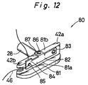
- Fig.12 is a perspective view of the bobbin holding member 80 illustrative of the fourth embodiment of the invention.
- the body 81 is made of a magnetic material and enables the bobbin thread tensioner spring 43 to magnetically attract and press the bobbin thread 46 against the side face 81a.
- a pressurizing section 84 Formed at the free end of the bobbin thread tensioner spring 82 is a pressurizing section 84 where the bobbin thread guiding slot 85 is formed.
- a mounting section 87 Formed between the base end section and the free end section of the bobbin thread tensioner spring 82 is a mounting section 87 with an adjust screw 86 screwed therein.
- the tip of the adjust screw 86 is in contact with a top face 81b of the body 81, and the bobbin thread tensioner spring 82 makes an angular displacement around the set screw 83 enabling to change the contact length of the bobbin thread 46 which is interposed between the pressurizing section 84 and the side face 81a of the body 81, by turning the adjust screw 86 forward or backward.
Abstract
Description
- The present invention relates to a bobbin holding structure to house and hold a bobbin in a bobbin case holder.
- Fig.1 is a perspective view of a typical prior art. Fig.2 is a perspective view of a
bobbin 5. Fig.3 is a perspective view of abobbin case 6 where thebobbin case 6 is shown partially cut away. - For example, a horizontal axis full
rotary looptaker 1 provided in a lock stitch sewing machine has a rotatinghook 3 where arotary shaft 2 driven to rotate around a horizontal axis is fixed and abobbin case holder 4 which is housed in the rotatinghook 3, while thebobbin case holder 4 is provided with abobbin case 6 which houses abobbin 5. Thebobbin case holder 4 is locked from rotating by arotation stopper member 7, and when therotary shaft 2 is driven to rotate, therotating hook 3 rotates around the rotary axis while thebobbin case holder 4 remains stationary. - Fig.4 is a perspective view of the horizontal axis full
rotary looptaker 1 with thebobbin 5 and thebobbin case 6 removed therefrom. Fig.5 is a partially enlarged perspective view of thebobbin case 6. With reference made also to Fig.1 through Fig.3, astud 9 is provided vertically toward the opening on thebottom 8 of thebobbin case holder 4. As shown in Fig.3, ahollow shaft 10 of straight cylindrical shape is formed in thebobbin case 6. Thehollow shaft 10 is inserted through acentral hole 11 of thebobbin 5, and thebobbin 5 is housed in thebobbin case 6. Thebobbin case 6 which houses thebobbin 5 is housed in thebobbin case holder 4 with thestud 9 inserted through thehollow shaft 10. - Under such a condition where the
bobbin 5 is housed in thebobbin case holder 4, alocking piece 13 which is provided in thebobbin case 6 is locked in thelocking groove 12 which is formed at a free end of thestud 9, thereby locking thebobbin case 6 in thebobbin case holder 4. Thus thebobbin 5 is retained in thebobbin case holder 4 by thebobbin case 6. In order to take thebobbin 5 out of thebobbin case holder 4, apivotable flap 14 is operated to release the lock between thelocking piece 13 and thestud 9 and, under this condition, thebobbin case 6 is taken out of thebobbin case holder 4 and thebobbin 5 is taken out of thebobbin case 6. - In such a prior art as described above, it takes much time to replace the bobbin resulting in poor operability. Moreover, the mechanism of holding the bobbin is complicated.
- An object of the invention is to provide a bobbin holding mechanism which enables it possible to easily attach and detach the bobbin in and from the bobbin case holder, and is capable of securely holding the bobbin in the bobbin case holder in a simple structure.
- The invention provides a bobbin holding mechanism where a bobbin holding member which attracts the bobbin to a bobbin case holder which houses the bobbin is mounted freely detachably.
- In a preferred embodiment of the invention, the bobbin holding member has a bobbin thread tensioning function.
- In another preferred embodiment of the invention, the bobbin thread tensioning function is achieved by a bobbin thread tensioner spring attached to the bobbin holding member.
- In accordance to the invention, the bobbin holding member is provided which attracts the bobbin to the bobbin case holder which houses the bobbin. This constitution enables it to hold the bobbin securely within the bobbin case holder without allowing the bobbin to come off the bobbin case holder during sewing operation. Also because the bobbin holding member is installed detachably in the bobbin case holder, the bobbin can be replaced easily and the efficiency of sewing operation can be improved.
- In accordance to the invention, it is made possible to hold the bobbin housed in the bobbin case holder securely by the bobbin holding member without allowing the bobbin to come off the bobbin case holder. Because the bobbin holding member is installed in the bobbin case holder freely detachably, the bobbin can be easily taken out of the bobbin case holder. This enables to replace the bobbin quickly and easily, resulting in improved work efficiency. The bobbin holding mechanism of the invention can be implemented in a rotating hook of the prior art, making it possible to embody the invention widely in relation to existing sewing machines.
- The invention provides a bobbin holding mechanism comprising;
a body installed along diameter of the bobbin case holder at an end face of the bobbin case holder made of a ferromagnetic material at the open end side of the bobbin case holder, and has a key slot formed at both ends in the longitudinal direction to accommodate the end face to fit therein,
a shaft provided vertically at the center of the body in the longitudinal direction, of which tip extends to near the bottom of the bobbin case holder under the condition that the body is installed in the bobbin case holder,
a bobbin thread tensioner spring of which base end is attached to the body and a bobbin thread guide slot to pass the bobbin thread is formed at a free end thereof, the free end making elastic contact with a side face of the body on the open side,
a screw member provided on the bobbin thread tensioner spring which displaces the bobbin thread tensioner spring in a direction to approach to or go away from the body, to change the pressure against the side face of the free end, and
an attraction piece which is installed at the tip of the shaft and is made of a magnetic material,
where the shaft is inserted through a cylinder of the bobbin and the attraction piece is magnetically attracted to the bottom of the bobbin case holder to retain the bobbin in the bobbin case holder. - In accordance to the invention, under the condition that the bobbin holding member is installed in the bobbin case holder, the body is disposed in the direction of diameter of the bobbin case holder and the free end of the bobbin case holder fits in the key slot, thereby preventing displacement in the direction of diameter and enabling to position the body with respect to the bobbin case holder. Under this condition, tip of the shaft extends to near the bottom of the bobbin case holder, and the attraction piece provided at the tip thereof magnetically adheres to the bottom, to retain the bobbin in the bobbin case holder under this condition. This constitution makes it possible to change the bobbin easily and quickly, minimize the time taken to change the bobbin and improve the efficiency of sewing work. Also because the body is equipped with the bobbin thread tensioner spring, the bobbin thread lead from the bobbin which is retained in the bobbin case holder can be properly tensioned, thereby enabling to form stitches of good quality without allowing slack in the thread.
- In accordance with the invention, the bobbin housed in the bobbin case holder can be securely retained in the bobbin case holder by the bobbin holding member without allowing to come of the bobbin case holder. Because the bobbin holding member is installed in the bobbin case holder freely detachably, the bobbin can be easily removed from the bobbin case holder. This enables to replace the bobbin quickly improving the work efficiency. The bobbin holding mechanism of the invention is simpler in it constitution than in the case of the bobbin cases of the prior art and therefore provides for better productivity, enabling to manufacture at a lower cost. Moreover the bobbin holding mechanism of the invention enables to replace only the bobbin case holder unlike the rotating hooks of the prior art, and therefore can be applied widely in relation to the rotating hooks installed in the existing sewing machines.
- Other and further objects, features and advantages of the invention will be more explicit from the following detailed description taken with reference to the drawings wherein:
- Fig.1 is a perspective view of typical prior art;
- Fig.2 is a perspective view of the
bobbin 5; - Fig.3 is a perspective view of the
bobbin case 6; - Fig.4 is a perspective view of the horizontal axis full
rotary looptaker 1 with thebobbin 5 and thebobbin case 6 removed therefrom; - Fig.5 is a partially enlarged cross sectional drawing of the
bobbin case 6; - Fig.6 is a perspective view of the
bobbin holding member 20 illustrative of the first embodiment of the invention. Fig.7 is a perspective view of the horizontal axis fullrotary looptaker 21 which is equipped with thebobbin holding member 20; - Fig.8 is a perspective view of the
bobbin holding member 40 illustrative of the second embodiment of the invention; - Fig.9 is an enlarged perspective view of the
bobbin holding member 40; - Fig.10 is a partially enlarged perspective view of the bobbin
thread tensioner spring 43; - Fig.11 is a perspective view of the
bobbin holding member 60 illustrative of the third embodiment of the invention; and - Fig.12 is a perspective view of the
bobbin holding member 80 illustrative of the fourth embodiment of the invention. - Now referring to the drawing, preferred embodiments of the invention are described below.
- Fig.6 is a perspective view of the
bobbin holding member 20 illustrative of an embodiment of the invention, and Fig.7 is a perspective view of the horizontal axisfull rotary looptaker 21 which is equipped with thebobbin holding member 20. In Fig.1, thebobbin holding member 20 is shown partially cut away. The horizontal axisfull rotary looptaker 21 installed in a lock stitch sewing machine is provided with arotating hook 23 with arotary shaft 22 fixed thereto which is driven to rotate around a horizontal rotary axis and abobbin case holder 24 which is made of a ferromagnetic material such as iron and is housed in therotating hook 23, and thebobbin holding member 20 with thebobbin 25 housed therein is installed in thebobbin case holder 24. - The
bobbin case holder 24 is prevented from rotating by arotation stopper 26 and, under this condition, the rotatinghook 23 is driven to rotate around the rotary axis thereof. In this embodiment, the bottom 27 of thebobbin case holder 24 is flat because it is not necessary to install the stud 9 (Refer to Fig.4) described in the prior art. - The
bobbin holding member 20 has a cylindrically shapedshaft 28 which extends along thecenter axis 11 thereof. Formed at the tip of theshaft 28 is arecess 29 with anattraction piece 30 made of a magnetic material such as a permanent magnet fixed therein. By housing thebobbin 25 in such abobbin holding member 20 and installing it in thebobbin case holder 24, thebobbin 25 can be retained securely in thebobbin case holder 24 by the magnetic attraction of theattraction piece 30 to the bottom 27. When taking thebobbin 25 out of thebobbin case holder 24, thebobbin 25 housed in thebobbin holding member 20 can be taken out easily by picking thebobbin holding member 20 and taking it out of thebobbin case holder 24. - In another embodiment, installation of a cylindrical attraction piece in a
hollow shaft 10 of theconventional bobbin case 6 makes it possible to use the conventionalbobbin case holder 4, enabling to embody the invention widely in relation to existing rotating hooks. - Fig.8 is a perspective view of the
bobbin holding member 40 installed in the horizontal axisfull rotary looptaker 21 of the second embodiment of the invention. Fig.9 is an enlarged perspective view of thebobbin holding member 40. Fig.10 is a partially enlarged perspective view of the bobbinthread tensioner spring 43. Parts which correspond to those of the embodiment mentioned above are assigned the same reference numbers. With reference made also to Fig.6 and Fig.7, thebobbin holding member 40 of the embodiment includes thebody 41 which is installed at theend face 24a of thebobbin case holder 24 on the open end side along the direction of the diameter thereof, and ashaft 28 which is vertically disposed at the center of thebody 41 in the longitudinal direction. - The
body 41 hasfitting slots fitting slots end face 24a of thebobbin case holder 24 to enable to install thebobbin holding member 40 in the bobbin case holder so that the axis of theshaft 28 agrees with the center axis of the bobbin case holder. Installed on thebody 41 is the bobbinthread tensioner spring 43 of curved plate shape with the base end sections thereof fixed withscrews 44. - Freely passing through near the center of the bobbin
thread tensioner spring 43 in the longitudinal direction is an adjustscrew 45 which is screwed in a screw hole formed in thebody 41. Formed at the free end section of the bobbinthread tensioner spring 43 is a pressurizingsection 47 which makes elastic contact with oneside 41a of thebody 41 and pressurizes thebobbin thread 46. In the pressurizingsection 47, a bobbinthread guiding slot 48 is formed as shown in Fig.10. Thebobbin thread 46 is passed through the bobbinthread guiding slot 48, and is elastically pressed against theside face 41a by the pressurizingsection 47. - By turning the adjust
screw 45 forward or backward under this condition, the force of pressing the bobbin thread can be adjusted. Therefore it is made possible to apply a proper tension by the rotary action of therotating hook 23 to thebobbin thread 46 which is taken out of thebobbin 25, enabling to perform sewing operation with desired thread tension. - Fig.11 is a perspective view of the bobbin holding member illustrative of the third embodiment of the invention. The
body 61 of thebobbin holding member 60 of the embodiment has a bobbin thread guiding piece 62 formed integrally therewith. The bobbin thread guiding piece 62 has anotch 63 wherein thebobbin thread 46 fits, formed thereon. Thebobbin thread 46 taken out of thebobbin 25 passes through the bobbinthread guiding slot 48, elastically pressed by the pressurizingsection 47 against theside face 61a of thebody 61, and is passed through thenotch 63 to be taken out. - This constitution also makes it possible to retain the
bobbin 25 in thebobbin case holder 24 and applying a proper tension to thebobbin thread 46 to take it out with the desired thread tension. Because thefitting slot 42b (Fig.9) described in relation to the previous embodiment is not formed in this embodiment, thebobbin holding member 60 may be magnetically attracted to theend face 24a of thebobbin case holder 24 by magnetizing thebody 61 at around the point indicated by thereference number 64. By this configuration, thebobbin holding member 60 can be installed securely without allowing thebobbin holding member 60 to displace laterally on theend face 24a of thebobbin case holder 24 during sewing operation. - Fig.12 is a perspective view of the
bobbin holding member 80 illustrative of the fourth embodiment of the invention. Installed on the base end section of thebody 81 of thebobbin holding member 80 of the embodiment by means ofset screws 83 is the bobbinthread tensioner spring 82. Thebody 81 is made of a magnetic material and enables the bobbinthread tensioner spring 43 to magnetically attract and press thebobbin thread 46 against theside face 81a. - Formed at the free end of the bobbin
thread tensioner spring 82 is a pressurizingsection 84 where the bobbinthread guiding slot 85 is formed. Formed between the base end section and the free end section of the bobbinthread tensioner spring 82 is a mountingsection 87 with an adjustscrew 86 screwed therein. The tip of the adjustscrew 86 is in contact with atop face 81b of thebody 81, and the bobbinthread tensioner spring 82 makes an angular displacement around theset screw 83 enabling to change the contact length of thebobbin thread 46 which is interposed between the pressurizingsection 84 and theside face 81a of thebody 81, by turning the adjustscrew 86 forward or backward. - Therefore when the contact length of the
bobbin thread 46 is made longer, it is possible to apply a friction force to the bobbin thread which passes between the pressurizingsection 84 and theside face 81b and reduce the friction force as the contact length is decreased. This enables to apply a proper tension to thebobbin thread 46 to perform sewing operation with the desired thread tension. - As described above, by means of the
bobbin holding members bobbin 25 and perform sewing operation with the desired thread tension. - The invention may be embodied in other specific forms without departing from the spirit or essential characteristics thereof. The present embodiments are therefore to be considered in all respects as illustrative and not restrictive, the scope of the invention being indicated by the appended claims rather than by the foregoing description and all changes which come within the meaning and the range of equivalency of the claims are therefore intended to be embraced therein.
Claims (4)
- a bobbin holding mechanism where the bobbin holding member (20, 40, 60, 80) which magnetically adheres to the bobbin case holder (24) which houses the bobbin (25) is detachably installed.
- a bobbin holding mechanism as claimed in claim 1, wherein the bobbin holding member (80) has bobbin thread tensioning function.
- A bobbin holding mechanism as claimed in claim 2, wherein the bobbin thread tensioning function is achieved by a bobbin thread tensioner spring (43, 82) which is mounted on the bobbin holding member (40, 60, 80).
- A bobbin holding mechanism comprising;
a body (41, 61, 81) which is installed at an end face (24a) of a bobbin case holder (24) having a bottom (27) and made of a ferromagnetic material on the open end side along the diameter direction of the bobbin case holder (24), and has fitting slots (42a, 42b) formed at both ends in the longitudinal direction wherein the end face (24a) fits in,
a shaft (28) which is vertically disposed at the center in the longitudinal direction of the body (41), and the tip thereof extends to near the bottom (27) of the bobbin case holder (24) under the condition that the body (41) is installed in the bobbin case holder (24),
a bobbin thread tensioner spring (43, 82) the base end section thereof is mounted on the body (41), which has a bobbin thread guiding slot (48) formed at the free end section to allow the bobbin thread (46) passes through, and the free end section makes elastic contact with the side face (41a) of the body (41) on the open end side,
a screw member (45) which is installed on the bobbin thread tensioner spring (43, 82) and changes the pressing force against the side face (41a) of the free end section by displacing the bobbin thread tensioner spring (43, 82) in the direction to approach or go away from the body (41), and
an attraction piece (30) which is installed at the tip of the shaft and is made of a magnetic material, wherein
the shaft (28) is passed through the cylinder of the bobbin to retain the bobbin (25) in the bobbin case holder (24) by causing the attraction piece (30) to the bottom (27) of the bobbin case holder (27).
Priority Applications (3)
| Application Number | Priority Date | Filing Date | Title |
|---|---|---|---|
| US07/626,288 US5152236A (en) | 1990-12-13 | 1990-12-12 | Bobbin holding structure |
| DE69032163T DE69032163T2 (en) | 1990-12-13 | 1990-12-13 | Bracket for the bobbin case in a sewing machine |
| EP90203282A EP0489980B1 (en) | 1990-12-13 | 1990-12-13 | Bobbin holding structure |
Applications Claiming Priority (1)
| Application Number | Priority Date | Filing Date | Title |
|---|---|---|---|
| EP90203282A EP0489980B1 (en) | 1990-12-13 | 1990-12-13 | Bobbin holding structure |
Publications (2)
| Publication Number | Publication Date |
|---|---|
| EP0489980A1 true EP0489980A1 (en) | 1992-06-17 |
| EP0489980B1 EP0489980B1 (en) | 1998-03-18 |
Family
ID=8205193
Family Applications (1)
| Application Number | Title | Priority Date | Filing Date |
|---|---|---|---|
| EP90203282A Expired - Lifetime EP0489980B1 (en) | 1990-12-13 | 1990-12-13 | Bobbin holding structure |
Country Status (3)
| Country | Link |
|---|---|
| US (1) | US5152236A (en) |
| EP (1) | EP0489980B1 (en) |
| DE (1) | DE69032163T2 (en) |
Cited By (4)
| Publication number | Priority date | Publication date | Assignee | Title |
|---|---|---|---|---|
| DE19840956C1 (en) * | 1998-09-08 | 2000-02-24 | Gerd Papajewski | Looper for lower thread in double lock stitch sewing machine has extractor with magnetic attraction to pull the bobbin and upper section of the bobbin housing clear of the lower housing section |
| WO2001092623A2 (en) * | 2000-05-27 | 2001-12-06 | Philipp Moll | Device used on sewing or knitting machines for changing the bobbin containing the looper thread |
| EP2189565A2 (en) | 2008-11-25 | 2010-05-26 | Daniele Cerliani | Rotary hook for a lockstitch sewing machine, comprising means to reduce the noise thereof |
| EP2444538A1 (en) * | 2009-06-16 | 2012-04-25 | NSD Corporation | Lower-thread tension control device for sewing machine, and sewing machine |
Families Citing this family (7)
| Publication number | Priority date | Publication date | Assignee | Title |
|---|---|---|---|---|
| US5842431A (en) * | 1997-02-19 | 1998-12-01 | Wu; Chong-Ming | Rotating shuttle and presser plate arrangement |
| US5921192A (en) * | 1998-01-22 | 1999-07-13 | Bakron Corporation | Bobbin assembly with structure for severing improperly routed thread |
| US6257512B1 (en) * | 1998-12-16 | 2001-07-10 | Fil-Tec, Inc. | Magnetized pre-wound sideless bobbins |
| US6076477A (en) * | 1999-05-21 | 2000-06-20 | Badillo; Paul | Hook system for sewing machine |
| US6659384B2 (en) | 2001-08-21 | 2003-12-09 | J. & P. Coats Limited | Pre-wound bobbin with magnetized flange |
| CH706089A8 (en) * | 2012-02-02 | 2013-10-31 | Bernina Int Ag | Gripper arrangement for a sewing machine. |
| DE102015111580A1 (en) * | 2014-08-05 | 2016-02-11 | Cm Cerliani S.R.L. | Gripper for a lockstitch sewing machine with stable tension of the bobbin thread |
Citations (2)
| Publication number | Priority date | Publication date | Assignee | Title |
|---|---|---|---|---|
| CH332443A (en) * | 1953-04-09 | 1958-09-15 | Messerschmitt Ag | Grippers for sewing machines |
| GB1000481A (en) * | 1960-10-13 | 1965-08-04 | British United Shoe Machinery | Improvements in or relating to sewing machines |
Family Cites Families (9)
| Publication number | Priority date | Publication date | Assignee | Title |
|---|---|---|---|---|
| US1179371A (en) * | 1913-06-12 | 1916-04-11 | Singer Mfg Co | Sewing-machine loop-taker. |
| US1981834A (en) * | 1932-12-29 | 1934-11-20 | Singer Mfg Co | Thread cases for sewing machine loop-takers |
| US2763227A (en) * | 1953-12-30 | 1956-09-18 | Birtman Electric Co | Bobbin case |
| US3051108A (en) * | 1961-08-24 | 1962-08-28 | Singer Mfg Co | Tension release mechanism for sewing machines |
| US4235178A (en) * | 1979-03-26 | 1980-11-25 | Union Special Corporation | Bobbin thread tension device |
| JPS6117736Y2 (en) * | 1980-09-26 | 1986-05-30 | ||
| JPS57134189A (en) * | 1981-02-13 | 1982-08-19 | Aisin Seiki | Horizontal unit pattern device for sewing machine |
| JPS61176397A (en) * | 1985-01-30 | 1986-08-08 | 株式会社廣瀬製作所 | Rotary hook |
| DE3537391C1 (en) * | 1985-10-21 | 1987-05-07 | Duerkoppwerke | Thread tensioning device for the looper thread of a lockstitch looper |
-
1990
- 1990-12-12 US US07/626,288 patent/US5152236A/en not_active Expired - Lifetime
- 1990-12-13 EP EP90203282A patent/EP0489980B1/en not_active Expired - Lifetime
- 1990-12-13 DE DE69032163T patent/DE69032163T2/en not_active Expired - Fee Related
Patent Citations (2)
| Publication number | Priority date | Publication date | Assignee | Title |
|---|---|---|---|---|
| CH332443A (en) * | 1953-04-09 | 1958-09-15 | Messerschmitt Ag | Grippers for sewing machines |
| GB1000481A (en) * | 1960-10-13 | 1965-08-04 | British United Shoe Machinery | Improvements in or relating to sewing machines |
Cited By (12)
| Publication number | Priority date | Publication date | Assignee | Title |
|---|---|---|---|---|
| DE19840956C1 (en) * | 1998-09-08 | 2000-02-24 | Gerd Papajewski | Looper for lower thread in double lock stitch sewing machine has extractor with magnetic attraction to pull the bobbin and upper section of the bobbin housing clear of the lower housing section |
| US6112684A (en) * | 1998-09-08 | 2000-09-05 | Papajewski; Gerd | Magnetic revolving shuttle for double-stitch sewing machines |
| WO2001092623A2 (en) * | 2000-05-27 | 2001-12-06 | Philipp Moll | Device used on sewing or knitting machines for changing the bobbin containing the looper thread |
| WO2001092623A3 (en) * | 2000-05-27 | 2002-04-11 | Philipp Moll | Device used on sewing or knitting machines for changing the bobbin containing the looper thread |
| EP2189565A2 (en) | 2008-11-25 | 2010-05-26 | Daniele Cerliani | Rotary hook for a lockstitch sewing machine, comprising means to reduce the noise thereof |
| ITMI20082105A1 (en) * | 2008-11-25 | 2010-05-26 | Daniele Cerliani | ROTARY CROCHET FOR SEWING MACHINE WITH POINTED TAPES INCLUDING MEANS TO REDUCE ITS NOISE |
| CN101736535A (en) * | 2008-11-25 | 2010-06-16 | 达尼埃莱·切利亚尼 | Rotary hook for a locksmith sewing machine, comprising means to reduce the noise thereof |
| EP2189565A3 (en) * | 2008-11-25 | 2010-08-18 | Daniele Cerliani | Rotary hook for a lockstitch sewing machine, comprising means to reduce the noise thereof |
| US8342110B2 (en) | 2008-11-25 | 2013-01-01 | Daniele Cerliani | Rotary hook for a locksmith sewing machine, comprising means to reduce the noise thereof |
| CN101736535B (en) * | 2008-11-25 | 2013-11-06 | 达尼埃莱·切利亚尼 | Rotary hook for a locksmith sewing machine, comprising means to reduce the noise thereof |
| EP2444538A1 (en) * | 2009-06-16 | 2012-04-25 | NSD Corporation | Lower-thread tension control device for sewing machine, and sewing machine |
| EP2444538A4 (en) * | 2009-06-16 | 2015-04-15 | Nsd Corp | Lower-thread tension control device for sewing machine, and sewing machine |
Also Published As
| Publication number | Publication date |
|---|---|
| US5152236A (en) | 1992-10-06 |
| EP0489980B1 (en) | 1998-03-18 |
| DE69032163D1 (en) | 1998-04-23 |
| DE69032163T2 (en) | 1998-07-30 |
Similar Documents
| Publication | Publication Date | Title |
|---|---|---|
| EP0489980A1 (en) | Bobbin holding structure | |
| US8640637B2 (en) | Sewing-machine bobbin thread tension controller, and sewing machine | |
| US4733622A (en) | Thread end holder for sewing machine with thread winding bobbin | |
| US4263859A (en) | Thread handling system for a sewing machine | |
| US4632048A (en) | Method of controlling upper thread in sewing machine | |
| CN111691081B (en) | Bottom thread supply device of sewing machine | |
| US4421041A (en) | Needle design and clamping system | |
| TWI734712B (en) | Needle clamping device of sewing machine | |
| US4421042A (en) | Sewing machine head end module construction | |
| US4300463A (en) | Needle threading device for sewing machines | |
| US4137858A (en) | Gripper and bobbin assembly for double-lock-stitch sewing machine | |
| US3927631A (en) | Thread tensioner with improved yawn mechanism | |
| JPH11309288A (en) | Sewing machine and needle holding device for sewing machine | |
| EP3257992B1 (en) | Vertical full rotation shuttle | |
| CZ265195A3 (en) | Device for cutting-off a thread on a sewing machine | |
| JPH0268096A (en) | Full rotary hook for lock stitch sewing machine | |
| KR20040007300A (en) | Bobbin case | |
| CN215209985U (en) | Embroidery machine dynamic holding mechanism | |
| US3016031A (en) | Needle clamps for sewing machines | |
| US2419698A (en) | Thread case and carrier therefor for lock-stitch sewing machines | |
| CN214882231U (en) | Computer embroidery machine with dynamic holding mechanism | |
| JPH0214080B2 (en) | ||
| US2742008A (en) | Bobbin-thread cases | |
| EP0086794B1 (en) | A loop-taker mechanism in a sewing machine | |
| JP2001303424A (en) | Embroidering machine |
Legal Events
| Date | Code | Title | Description |
|---|---|---|---|
| PUAI | Public reference made under article 153(3) epc to a published international application that has entered the european phase |
Free format text: ORIGINAL CODE: 0009012 |
|
| AK | Designated contracting states |
Kind code of ref document: A1 Designated state(s): DE ES FR GB IT |
|
| 17P | Request for examination filed |
Effective date: 19920728 |
|
| 17Q | First examination report despatched |
Effective date: 19940614 |
|
| GRAG | Despatch of communication of intention to grant |
Free format text: ORIGINAL CODE: EPIDOS AGRA |
|
| GRAG | Despatch of communication of intention to grant |
Free format text: ORIGINAL CODE: EPIDOS AGRA |
|
| GRAH | Despatch of communication of intention to grant a patent |
Free format text: ORIGINAL CODE: EPIDOS IGRA |
|
| GRAH | Despatch of communication of intention to grant a patent |
Free format text: ORIGINAL CODE: EPIDOS IGRA |
|
| GRAA | (expected) grant |
Free format text: ORIGINAL CODE: 0009210 |
|
| AK | Designated contracting states |
Kind code of ref document: B1 Designated state(s): DE ES FR GB IT |
|
| PG25 | Lapsed in a contracting state [announced via postgrant information from national office to epo] |
Ref country code: FR Free format text: LAPSE BECAUSE OF FAILURE TO SUBMIT A TRANSLATION OF THE DESCRIPTION OR TO PAY THE FEE WITHIN THE PRESCRIBED TIME-LIMIT Effective date: 19980318 Ref country code: ES Free format text: THE PATENT HAS BEEN ANNULLED BY A DECISION OF A NATIONAL AUTHORITY Effective date: 19980318 |
|
| REF | Corresponds to: |
Ref document number: 69032163 Country of ref document: DE Date of ref document: 19980423 |
|
| ITF | It: translation for a ep patent filed |
Owner name: STUDIO TORTA S.R.L. |
|
| EN | Fr: translation not filed | ||
| PG25 | Lapsed in a contracting state [announced via postgrant information from national office to epo] |
Ref country code: GB Free format text: LAPSE BECAUSE OF NON-PAYMENT OF DUE FEES Effective date: 19981213 |
|
| PLBE | No opposition filed within time limit |
Free format text: ORIGINAL CODE: 0009261 |
|
| STAA | Information on the status of an ep patent application or granted ep patent |
Free format text: STATUS: NO OPPOSITION FILED WITHIN TIME LIMIT |
|
| 26N | No opposition filed | ||
| GBPC | Gb: european patent ceased through non-payment of renewal fee |
Effective date: 19981213 |
|
| PGFP | Annual fee paid to national office [announced via postgrant information from national office to epo] |
Ref country code: DE Payment date: 20041209 Year of fee payment: 15 |
|
| PG25 | Lapsed in a contracting state [announced via postgrant information from national office to epo] |
Ref country code: IT Free format text: LAPSE BECAUSE OF NON-PAYMENT OF DUE FEES Effective date: 20051213 |
|
| PG25 | Lapsed in a contracting state [announced via postgrant information from national office to epo] |
Ref country code: DE Free format text: LAPSE BECAUSE OF NON-PAYMENT OF DUE FEES Effective date: 20060701 |