EP2189379B1 - Klappbarer Transport- und Lagerbehälter aus Kunststoff - Google Patents
Klappbarer Transport- und Lagerbehälter aus Kunststoff Download PDFInfo
- Publication number
- EP2189379B1 EP2189379B1 EP09177109A EP09177109A EP2189379B1 EP 2189379 B1 EP2189379 B1 EP 2189379B1 EP 09177109 A EP09177109 A EP 09177109A EP 09177109 A EP09177109 A EP 09177109A EP 2189379 B1 EP2189379 B1 EP 2189379B1
- Authority
- EP
- European Patent Office
- Prior art keywords
- container
- latching
- projection
- parts
- lever
- Prior art date
- Legal status (The legal status is an assumption and is not a legal conclusion. Google has not performed a legal analysis and makes no representation as to the accuracy of the status listed.)
- Not-in-force
Links
- 238000003860 storage Methods 0.000 title claims abstract description 17
- 238000000034 method Methods 0.000 description 7
- 238000004519 manufacturing process Methods 0.000 description 5
- 238000005452 bending Methods 0.000 description 4
- 230000006378 damage Effects 0.000 description 4
- 238000001746 injection moulding Methods 0.000 description 4
- 230000005540 biological transmission Effects 0.000 description 3
- 239000000463 material Substances 0.000 description 3
- 239000002131 composite material Substances 0.000 description 2
- 238000009826 distribution Methods 0.000 description 2
- 230000002441 reversible effect Effects 0.000 description 2
- 230000001419 dependent effect Effects 0.000 description 1
- 210000003746 feather Anatomy 0.000 description 1
- 238000003825 pressing Methods 0.000 description 1
- 239000000243 solution Substances 0.000 description 1
- 230000007704 transition Effects 0.000 description 1
- 238000009827 uniform distribution Methods 0.000 description 1
Images



Classifications
-
- B—PERFORMING OPERATIONS; TRANSPORTING
- B65—CONVEYING; PACKING; STORING; HANDLING THIN OR FILAMENTARY MATERIAL
- B65D—CONTAINERS FOR STORAGE OR TRANSPORT OF ARTICLES OR MATERIALS, e.g. BAGS, BARRELS, BOTTLES, BOXES, CANS, CARTONS, CRATES, DRUMS, JARS, TANKS, HOPPERS, FORWARDING CONTAINERS; ACCESSORIES, CLOSURES, OR FITTINGS THEREFOR; PACKAGING ELEMENTS; PACKAGES
- B65D11/00—Containers having bodies formed by interconnecting or uniting two or more rigid, or substantially rigid, components made wholly or mainly of plastics material
- B65D11/18—Containers having bodies formed by interconnecting or uniting two or more rigid, or substantially rigid, components made wholly or mainly of plastics material collapsible, i.e. with walls hinged together or detachably connected
- B65D11/1833—Containers having bodies formed by interconnecting or uniting two or more rigid, or substantially rigid, components made wholly or mainly of plastics material collapsible, i.e. with walls hinged together or detachably connected whereby all side walls are hingedly connected to the base panel
Definitions
- the invention relates to a transport and storage container made of plastic, in particular a stackable and foldable storage order box.
- the WO 9749613 a box-shaped container made of plastic, which has hinged side walls.
- the DE 42 44 359 C2 discloses a device for the automatic filling of flat collapsible, cuboid transport boxes.
- the DE 42 29 586 A1 disclosed a plastic transport box.
- Another box-shaped container with hinged side walls is from the DE 44 46 322 A1 and the WO 03/074376 A1 known.
- the WO 03/074 376 A1 discloses a transport and storage container according to the preamble of claim 1.
- the invention is the object of the invention to provide an improved transport and storage container.
- a transport and storage container is provided according to claim 1, wherein the container has a bottom, two opposing side parts and two opposing front parts, wherein the side parts and the front parts with hinges are hinged to the container center hinged to the ground.
- the side panels and the front parts are locked together in the erected state to form a mechanically stable overall composite.
- At least one of the side parts has a latching element for forming a releasable latching connection with one of the front parts, wherein this front part has an unlocking element, wherein the unlocking element is designed to release the latching connection due to a force on the unlocking element, wherein the force acting on the center of the container opposite side of this front part, ie done on the outside of this front part and towards the tank center.
- the transport and storage container according to the invention has the advantage that a collapse of an unfolded transport and storage container is possible in a simple manner. This is particularly important in automated storage facilities of great relevance.
- it is possible to initiate the collapsing process by a simple horizontal force from the outside, for example, on the front and side of the container on the corresponding unlocking.
- Elaborate additional tensile or compressive movements on this front are not necessary.
- the force which acts on the unlocking element for unlocking the releasable latching connection thereby also serves to initiate the Caribbeanklappvorgangs, that is, the flap of the corresponding front surface to the hinge device on the ground.
- the latching element has a latching projection for engagement in a counterpart recess of the front part.
- the locking projection on a second inclined surface wherein the second inclined surface is formed at the end of the locking projection and wherein the second inclined surface is inclined to the container center.
- the use of such a kind latching projection with a second inclined surface has the advantage that when assembling side part and corresponding front part of the locking projection is threaded self-finding in the counterpart recess of the front part.
- the latching projection has a first inclined surface, wherein the first inclined surface is formed at the end of the latching projection, wherein the first inclined surface is inclined away from the center of the container.
- an additional such a first inclined surface has the advantage that directed by a force, parallel to the corresponding side part and towards the center of the container, a resultant force acts perpendicular to the side part, whereby it is possible a corresponding unlocking element by such a force parallel to the side part and in the direction of the center of the container to initiate an unlocking process. Due to the resulting force perpendicular to the side part of the locking projection is driven from the counterpart recess of the front part, whereby a release of Fronteil and side part is possible.
- the latching element has an elastically resilient latching lever, wherein the latching lever is arranged in the plane of the side surface, wherein the latching projection is arranged on the latching lever and wherein the latching projection protrudes in the direction of the container center in the plane of the side surface.
- the unlocking element has an elastically resilient actuating element for receiving the force, wherein the actuating element has an actuating surface arranged in the plane of the front surface, wherein the actuating element has an edge projecting in the direction of the container center into the plane of the front surface. I'm upright Condition of the front parts and the side parts while the edge overlaps the locking projection at least partially, and also the edge is inclined to the actuating surface.
- the unlocking element of this type likewise has the advantage, like the latching element described above, that such an unlocking element can likewise be produced integrally in a simple and cost-effective manner, preferably together with the corresponding front part, in an injection molding process.
- Another advantage is that due to the simple mechanical design is given a high durability.
- no great attention must be paid to manufacturing tolerances, since it is only crucial that the edge partially overlaps the Council nose. The reason for this is that the oblique edge is pressed onto the latching lug by the action of force on the actuating surface, wherein due to the edge beveling, a resultant force acts on the latching lug in the direction of the corresponding side part.
- the locking lug is in turn driven out of the corresponding recess of the front part, so that thereupon a unlocking and thus a release of front part and side part for folding the same takes place.
- the edge is formed by a projection of the actuating element, wherein the projection cross-section tapers in the direction of the container center.
- the taper of the projection cross-section has the advantage that in an optimal manner forces acting on the actuating surface forces are distributed to the projection of the actuating element.
- the taper of the projection cross section is adapted in an optimal manner to the voltage profile in the projection cross section.
- the actuating element is formed by an operating lever arranged in the plane of the front surface, the edge projecting into the plane of the front surface being formed at the end of the lever.
- the actuating lever and the edge form an L-shape.
- the operating lever may have a wedge shape, wherein the edge is formed by one of the wedge surfaces of the wedge shape.
- the unlocking elements are integrally formed with the corresponding front parts and the latching elements integral with the corresponding side parts, so that a production of unlocking and locking element respectively together with the front and side parts in a common manufacturing process , For example, an injection molding process can be done.
- the container in the erected and / or collapsed state of the side parts and the front parts is stackable.
- FIG. 1 shows a transport and storage container 100, which preferably consists of plastic.
- the container consists of side parts 102 and front parts 104.
- the container 100 is shown in the unfolded state, so that the side parts 102 and the front parts 104 are each arranged perpendicular to each other and locked together.
- the front parts 104 and the side parts 102 are connected at the bottom with also not apparent hinges, so that the side and front parts to the container center 106 can be folded towards.
- FIG. 1 Important in the FIG. 1 is now that further locking elements 110 are provided on the side parts 102.
- the locking elements are used to form a releasable locking connection with the front parts 104.
- the front parts 104 release elements 108, wherein an unlocking operation can be initiated by pressing the unlocking.
- an unlocking process takes place by a force acting on the unlocking element 108 in the direction of the container center. The force also takes place on the side facing away from the container center side of the front part 104th
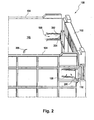
- FIG. 2 shows an enlarged schematic view of the container 100. Again, the front parts 104 and a side part 102 are shown. On the side part 102, the locking element 110 is arranged and on the front parts 104, the unlocking elements 108 are arranged.
- the unlocking elements 108 of a lever 202 and a projection 204 extends substantially parallel and in the plane of the front surface 104, whereas the projection 204 in the plane of the front surface in the direction of Container center protrudes.
- the actuation of the unlocking element 108 for example, as in the FIG. 2 shown by a force in the direction of 200, that is, by a force in the direction of the center of the container.
- a force in the direction of 200 that is, by a force in the direction of the center of the container.
- Characterized the viewer facing the front part 104 and the right side part 102 is unlocked from each other, since the projection 204 is pressed by the action of the actuating lever 202 in the direction of the container center, whereby a resultant force on the locking element 110 in the direction of the side part 102, that is to the right, works.
- the detent connection formed by the latching element is released.
- it is possible with a pivoting movement 206 to fold away the front front part in the direction of the container center.
- the folding process takes place independently due to the force acting in any case on the unlocking element 108 in the direction 200, that is towards the center of the container.
- FIG. 3 shows the container 100 in the unlocked state of the viewer facing the front part 104.
- the locking element 110 which is released due to the folding movement of the front part 104 in the direction 206, that is towards the center of the container.
- the axis 300 which by means of in the FIG. 3 not apparent hinges a folding operation of the front part 104 relative to the bottom 302 takes place.
- FIG. 4 shows a schematic cross-sectional view of a section of a transport and storage container.
- the front part 104 and the side part 102 are initially visible.
- the unlocking element 108 which, as already described with regard to FIG. 2 explained, consists of a lever 202 and a projection 204.
- the locking element 110 consists of a locking lever 400 and a locking projection 402, wherein the locking projection is arranged towards the container center 106 at the end of the locking lever and thereby projects into the plane of the side surface 102 ,
- Both the lever 202 and the locking lever 400 are elastically resilient.
- the latching projection 402 engages with a further latching lug, which is arranged in a direction perpendicular to the plane below or above the latching projection 402 on the latching projection in a counterpart recess of the front part 104 a.
- the latching projection 402 has an actuating surface 202 facing the inclined surface 403.
- the edge of the projection 204 is inclined towards the lever 202 and thereby at least partially overlaps the locking projection 402.
- This has the purpose that in the event of a force on the lever 200 in the direction 202, that is substantially perpendicular to the front side 104, said edge of Projection 204 is pressed against the locking projection 402.
- the force acts on the inclined surface 403 of the locking projection 402.
- the elastic locking element or the locking lever 400 together with the locking projection 402 in the direction 404, that is, swung away to the right of the container center 106.
- the latching connection between the side part 102 and the front part 104 is released, so that then in the direction 202, the front surface in the direction of the container center 106 can be folded.
- the fact that the locking projection 402 has the inclined surface 403, on which the force is exerted, is also in sudden large forces -. ensured by a blow to the actuating element 108 - a pivoting of the locking projection 402 in the direction 404. With a smooth surface in place of the sloping surface 403, a large, sudden force could result in material breakage because the detent projection 402 may not be pivoted so fast toward 404 and thus either break itself or cause breakage of the actuator.
- FIGS. 5a and 5b are only for understanding the invention. They do not represent embodiments of the invention.
- FIG. 5 shows schematically an unlocking process by such a corresponding force.
- a force acts in the direction 200 on the lever 202, the lever is moved about an axis 500 in the direction 200, for example.
- the projection 204 or its edge 506 is pressed onto the latching projection 402 of the latching element 110.
- a resultant force acts on the latching projection 402 in the direction 504.
- This resulting force in the direction 504 leads to a pivoting movement in the direction 404, the result of which in FIG. 5B is shown.
- FIG. 5b corresponding fictitious front and side parts are unlocked, since the unlocking element 108 has been moved in the direction 200 and thereby the locking element 110 has been pressed in the direction 404.
- the transition from FIG. 5a to FIG. 5b is reversible, since it is at the unlocking element 108 and the locking element 110 are elastic configurations, typically instead of a rotation of the lever 202 about the axis 500 and a rotation of the locking lever 400 about a fictitious axis 502, a bending operation of the actuating lever 202 and the Rasthebels 400 will take place.
- FIG. 6 shows various embodiments of locking and operating levers.
- the Figures 6a and 6b are only for understanding the invention. It does not represent an embodiment of the invention.
- FIG. 6a a combination of an actuating element with a latching element is shown, wherein the actuating element in the form of a wedge 600 is configured.
- One of the wedge surfaces forms that edge 506, which serves by movement of the wedge in the direction 200 for the action of force on the latching projection 402.
- edge 506 serves by movement of the wedge in the direction 200 for the action of force on the latching projection 402.
- FIG. 5 explains a resultant force exerted on the latching projection 402, so that a movement of the latching element in the direction 404 can take place.
- FIG. 6b a further alternative embodiment of a latching element b is shown.
- the locking element in the FIG. 6b has a latch lever 400 and a snap hook 602.
- the snap hook is provided for engaging behind a portion of the recess in the locked state of a front part not shown hereeineines the locking lever associated side part.
- the beveled surface of the snap-action hook 602 makes it possible in a simple manner for the snap-in hook to be able to slide into the recess of the front part during the locking process in a self-finding manner.
- FIG. 6c shows an alternative embodiment of a locking element, consisting of the locking lever 400, the locking projection 402 and a trapezoidal latching lug 604.
- the latching lug 604 is formed at the end of the latching projection 402.
- the trapezoidal detent 604 has a second inclined surface 606 and a first inclined surface 608.
- the sense of the first inclined surface 608, which is pointing away from the center of the container pointing the way, is to be seen in the fact that this ensures optimum force transmission of an edge 506 of a corresponding unlocking element on the latching projection 402 is.
- a force transmission to the latching projection 402 is indicated not exclusively along a line-shaped contact point between the edge 506 and projection 402, but along a contact surface which is formed by the surface 608 and the edge 506 in a planar manner.
- the power transmission from the edge 506 is significantly improved on the locking element.
- FIG. 7 an alternative embodiment can be seen in which, instead of an actuating lever, a resilient actuating element 702 is used in such a way that this resilient actuating element 702 is fastened by means of springs 704 on the front surface 104.
- the actuating element 702 has an actuating surface 706, wherein upon an action of force in the direction 200 on the actuating surface 706, the actuating element 702 in the direction 200, that is, in the direction of the container center, is pressed.
- the locking element 110 consisting of the locking lever 400 and the locking projection 402.
- the locking projection 402 engages in a corresponding recess 700 of the front surface 104 a.
- a latching lug 708 which protrudes perpendicularly from the locking lever 400 and which has a bevelled surface at its end.
- the detent 708 engages in the Figure 7a in a counterpart recess of the front surface 104, which results in that a movement of the front surface 104 in the direction 200 is prevented - the front surface is in the in Figure 7a fixed position shown.
- the actuator 702 is moved in the direction 200, the detent lever together with the detent 708 is moved in the direction 404 - the detent 708 is driven out of said counterpart recess.
- the front surface is no longer held by the latching lug 708 and a movement of the front surface in the direction 200 can take place.
- a pivot point 502 which takes place about a pivoting movement of the locking element 110 in the direction 404
- a bending operation of the locking element takes place, in particular a bending operation of the locking lever 400 in the direction 404.
- FIG. 8 shows an embodiment of the latching lever 400. It is tapered towards the actuating lever 202. This is advantageous since a uniform distribution of stress is achieved and thus material fatigue is reduced.
- a force acting on the detent lever 400 by the actuating lever 202 would result in greater stresses in the area further away from the actuating lever 202 than in the front area. Due to the increase in area of the detent lever 400 in this area, the voltages occurring are reduced. Due to the uniform increase in area over the entire region of the locking lever 400 thus a uniform stress distribution is achieved, whereby the material fatigue is reduced.
- Figure 9 is an enlarged detail of the tapered locking lever 400th
- FIG. 10 is a schematic view of a container corner with latched front 104 and side parts 102.
- FIG. 10a shows schematically the latching of the front 104 and side parts 102 by means of the latching projection 402 of the side part 102 with the inclined surface 403 and the projection 402 of the front part 104.
- the front and side parts define the container interior 106.
- Fig. 10b is a schematic view of a container corner with front and side parts as in Fig. 10a. The difference is that a force acts on the front part 104 in direction 200. It is therefore not exercised as in other figures, a force on the actuator, but to a different location of the front part 104. It is irrelevant whether this force acts selectively at a position of the front part 104, or whether it is a force on a partial surface or even the entire surface of the front part 104 is.
- the force in the direction 200 bends the front part 104. Since it is locked with the side part 102, the front part 104 bends in the middle more to the container interior 106 than at the edge in the vicinity of the side part 102. At a certain degree of bending, the projection 204 due the inclined surface 403 is no longer held by the locking projection 402 of the side part 102 and the front part 104 is the force direction 200 and tilts to the container interior 106. Due to the inclined surface 403, the tilting movement occurs to the container interior 106 rather than in the case of a straight surface. Thereby, damage to the front part 104, the projection 204 and the locking projection 402 can be prevented.
- the front part 104 is at a force in the direction 200 from a certain amount of force and folds to the container interior 106. This damage or even destruction of the container is prevented.
- the determined amount of force, from which the front part 104 works in the direction 200 can be determined by the bevel 403 of the locking projection 402. The steeper the slope 403 runs, the easier the front part 104 gives way to a force in the direction 200.
- the determined force is adjusted so that the front part 104 and the locking device consisting of latching projection 402 and projection 204 no Damage can occur if a force in the direction 200 acts on the front part 104.
Landscapes
- Engineering & Computer Science (AREA)
- Mechanical Engineering (AREA)
- Rigid Containers With Two Or More Constituent Elements (AREA)
- Containers Having Bodies Formed In One Piece (AREA)
Description
- Die Erfindung betrifft einen Transport- und Lagerbehälter aus Kunststoff, insbesondere einen stapelbaren und klappbaren Lagerordnungskasten.
- Aus dem Stand der Technik sind verschiedene klappbare Transport- und Lagerbehälter bekannt. Beispielsweise offenbart die
WO 9749613 DE 42 44 359 C2 offenbart eine Vorrichtung zum selbsttätigen Befüllen von flach zusammenlegbaren, quaderförmigen Transportkästen. DieDE 42 29 586 A1 offenbart einen Transportkasten aus Kunststoff. Ein weiterer kastenförmiger Behälter mit klappbaren Seitenwänden ist aus derDE 44 46 322 A1 und derWO 03/074376 A1 WO 03/074 376 A1 - Der Erfindung liegt demgegenüber die Aufgabe zugrunde, einen verbesserten Transport- und Lagerbehälter zu schaffen.
- Die der Erfindung zugrunde liegende Aufgabe wird mit den Merkmalen des unabhängigen Patentanspruchs gelöst. Bevorzugte Ausführungsformen der Erfindung sind in den abhängigen Patentansprüchen angegeben.
- Erfindungsgemäß wird ein Transport- und Lagerbehälter gemäß Anspruch 1 geschaffen, wobei der Behälter einen Boden, zwei sich gegenüberliegende Seitenteile und zwei sich gegenüberliegende Frontteile aufweist, wobei die Seitenteile und die Frontteile mit Scharnieren zur Behältermitte hin klappbar am Boden befestigt sind. Die Seitenteile und die Frontteile sind im aufgerichteten Zustand miteinander zur Bildung eines mechanisch stabilen Gesamtverbundes verriegelbar. Zur Verriegelung weist zumindest eines der Seitenteile ein Rastelement zur Ausbildung einer lösbaren Rastverbindung mit einem der Frontteile auf, wobei dieses Frontteil ein Entriegelungselement aufweist, wobei das Entriegelungselement zur Freigabe der Rastverbindung aufgrund einer Krafteinwirkung auf das Entriegelungselement ausgebildet ist, wobei die Krafteinwirkung auf der zur Behältermitte abgewandten Seite dieses Frontteils, d.h. auf die Außenseite dieses Frontteils und in Richtung zur Behältermitte erfolgt.
- Der erfindungsgemäße Transport- und Lagerbehälter hat den Vorteil, dass in einfacher Weise ein Zusammenklappen eines aufgeklappten Transport- und Lagerbehälters möglich ist. Dies ist insbesondere in automatisierten Lagereinrichtungen von großer Relevanz. Mit dem obig genannten Transport- und Lagerbehälter ist es möglich, durch eine einfache horizontale Krafteinwirkung von außen, beispielsweise auf die Front- und Sichtseite des Behälters, auf das entsprechende Entriegelungselement den Zusammenklappvorgang einzuleiten. Aufwendige zusätzliche Zug- oder Druckbewegungen auf diese Frontseite sind nicht notwendig. So muss beispiels weise nicht robotisch in den Innenraum des aufgeklappten Transport- und Lagerbehälters eingegriffen werden, um von dort aus mittels einer Zug- oder Druckbewegung den Zusammenklappvorgang durchzuführen.
- Damit ist es möglich, einen Zusammenklappvorgang eines solchen Transport- und Lagerbehälters zu automatisieren. Die Kraft, welche auf das Entriegelungselement zur Entriegelung der lösbaren Rastverbindung wirkt, dient dabei auch gleichzeitig zum Einleiten des Zusammenklappvorgangs, das heißt des Klappens der entsprechenden Frontfläche um die Scharniervorrichtung am Boden.
- Erfindungsgemäß weist das Rastelement einen Rastvorsprung zum Eingriff in eine gegenstückige Aussparung des Frontteils auf. Durch die Verwendung einer Aussparung des Frontteils und eines darin eingreifenden Rastvorsprungs ergibt sich der Vorteil, dass ein mechanisch stabiler Gesamtverbund der Front- und Seitenteile geschaffen werden kann. Eine Rüttelbewegung beispielsweise der Frontteile in einer Richtung parallel zu den Seitenteilen wird zu keiner Lösung der Rastverbindung führen, da ein solcher Rüttel- und Bewegungsvorgang lediglich Kräfte auf den Rastvorsprung überträgt, um daraufhin vom Rastvorsprung auf die Seitenteile übertragen und von diesen aufgenommen zu werden.
- Nach einer weiteren Ausführungsform der Erfindung weist der Rastvorsprung eine zweite geneigte Fläche auf, wobei die zweite geneigte Fläche am Ende des Rastvorsprungs ausgebildet ist und wobei die zweite geneigte Fläche zur Behältermitte hin geneigt ist. Die Verwendung eines solch gearteten Rastvorsprungs mit einer zweiten geneigten Fläche hat den Vorteil, dass beim Zusammenfügen von Seitenteil und entsprechendem Fronteil der Rastvorsprung selbstfindend in die gegenstückige Aussparung des Frontteils eingefädelt wird. Somit kann auch hier maschinell ein "Ausklappvorgang", das heißt ein Zusammenfügen der entsprechenden Front- und Seitenteile, erfolgen. Erfindungsgemäß weist der Rastvorsprung eine erste geneigte Fläche auf, wobei die erste geneigte Fläche am Ende des Rastvorsprungs ausgebildet ist, wobei die erste geneigte Fläche von der Behältermitte wegweisend geneigt ist. Die Verwendung einer zusätzlichen so gearteten ersten geneigten Fläche hat den Vorteil, dass durch eine Krafteinwirkung, parallel zum entsprechenden Seitenteil und in Richtung zur Behältermitte gerichtet, eine resultierende Kraft senkrecht zum Seitenteil wirkt, womit es einem entsprechend gearteten Entriegelungselement möglich ist, durch eine solche Krafteinwirkung parallel zum Seitenteil und in Richtung zur Behältermitte einen Entriegelungsvorgang einzuleiten. Durch die resultierende Kraft senkrecht zum Seitenteil wird der Rastvorsprung aus der gegenstückigen Aussparung des Frontteils getrieben, wodurch eine Entriegelung von Fronteil und Seitenteil möglich ist.
- Nach einer weiteren Ausführungsform der Erfindung weist das Rastelement einen elastisch federnden Rasthebel auf, wobei der Rasthebel in der Ebene der Seitenfläche angeordnet ist, wobei der Rastvorsprung am Rasthebel angeordnet ist und wobei der Rastvorsprung in Richtung zur Behältermitte in die Ebene der Seitenfläche hineinragt. Mittels des elastisch federnden Rasthebels kann in einfacher und kostengünstiger Weise ein Rastelement geschaffen werden, mit welchem sich eine lösbare Rastverbindung mit einem der Frontteile realisieren lässt. Durch die elastische Ausbildung des Rasthebels kann in reversibler Weise ein Ver- und Entrastvorgang unter Verwendung des Rastvorsprungs mit dem Frontteil stattfinden. Außerdem ist es durch die einfache mechanische Ausführung eines kombinierten Rasthebels und Rastvorsprungs möglich, ein solch geartetes Rastelement in einstückiger Weise mit einem Seitenteil zusammen herzustellen. Solches kann beispielsweise in einem Spritzgussverfahren stattfinden, wobei weitere Herstellungskosten für aufwendige Montageschritte beispielsweise eines Rastelements am Seitenteil entfallen.
- Nach einer weiteren Ausführungsform der Erfindung weist das Entriegelungselement ein elastisch federndes Betätigungselement zur Aufnahme der Krafteinwirkung auf, wobei das Betätigungselement eine in der Ebene der Frontfläche angeordnete Betätigungsfläche aufweist, wobei das Betätigungselement eine in Richtung zur Behältermitte in die Ebene der Frontfläche hineinragende Kante aufweist. Im aufgerichteten Zustand der Frontteile und der Seitenteile überlappt dabei die Kante den Rastvorsprung zumindest teilweise, wobei außerdem die Kante zur Betätigungsfläche hin geneigt ist.
- Das solch geartete Entriegelungselement hat ebenfalls wie das obig beschriebene Rastelement den Vorteil, dass ein solches Entriegelungselement ebenfalls in einfacher und kostengünstiger Weise, vorzugsweise zusammen mit dem entsprechenden Frontteil in einem Spritzgussverfahren einstückig hergestellt werden kann. Ein weiterer Vorteil ist, dass aufgrund der einfachen mechanischen Ausführung eine hohe Haltbarkeit gegeben ist. Außerdem muss bei einem entsprechenden Herstellungsverfahren keine große Rücksicht auf Fertigungstoleranzen genommen werden, da es lediglich entscheidend ist, dass die Kante die Ratsnase teilweise überlappt. Der Grund hierfür ist, dass durch die Krafteinwirkung auf die Betätigungsfläche die schräge Kante auf die Rastnase aufgepresst wird, wobei aufgrund der Kantenabschrägung eine resultierende Kraft auf die Rastnase in Richtung des entsprechenden Seitenteils wirkt. Damit wird die Rastnase wiederum aus der entsprechenden Aussparung des Frontteils getrieben, so dass daraufhin eine Entrastung und damit eine Freigabe von Frontteil und Seitenteil zum Zusammenklappen derselben erfolgt.
- Nach einer weiteren Ausführungsform der Erfindung wird die Kante durch einen Vorsprung des Betätigungselements gebildet, wobei sich der Vorsprungsquerschnitt in Richtung zur Behältermitte hin verjüngt. Die Verjüngung des Vorsprungsquerschnitts hat den Vorteil, dass in optimaler Weise bei Krafteinwirkung auf die Betätigungsfläche wirkende Kräfte auf den Vorsprung des Betätigungselements verteilt werden. Die Verjüngung des Vorsprungsquerschnitts ist dabei in optimaler Weise an den Spannungsverlauf im Vorsprungsquerschnitt angepasst.
- Nach einer weiteren Ausführungsform der Erfindung ist das Betätigungselement durch einen in der Ebene der Frontfläche angeordneten Betätigungshebel ausgebildet, wobei am Hebelende die in die Ebene der Frontfläche hineinragende Kante ausgebildet ist. Mittels eines solchen Betätigungshebels kann wiederum in einfacher und kostengünstiger Weise ein Betätigungselement realisiert werden, beispielsweise in einem Spritzgussverfahren wie obig beschrieben.
- Nach einer weiteren Ausführungsform der Erfindung bilden der Betätigungshebel und die Kante eine L-Form. Alternativ dazu kann der Betätigungshebel eine Keilform aufweisen, wobei die Kante durch eine der Keilflächen der Keilform gebildet wird.
- Nach einer weiteren Ausführungsform der Erfindung überlappen im aufgerichteten Zustand der Seitenteile und Frontteile die Seitenteile benachbarte Frontteile. Dies hat den Vorteil, dass eine Bewegung der Seitenteile hin zur Behältermitte verhindert wird, ohne dass hierbei eine hohe mechanische Beanspruchung etwaiger Rastverbindungen oder weiterer Haltemittel berücksichtigt werden müsste.
- Nach einer weiteren Ausführungsform der Erfindung sind wie bereits oben angemerkt, die Entriegelungselemente einstückig mit den entsprechenden Frontteilen und die Rastelemente einstückig mit den entsprechenden Seitenteilen ausgebildet, so dass eine Herstellung von Entriegelungs- und Rastelement jeweils zusammen mit den Front- und Seitenteilen in einem gemeinsamen Herstellungsverfahren, beispielsweise eines Spritzgussverfahrens, erfolgen kann.
- Nach einer weiteren Ausführungsform der Erfindung ist der Behälter im aufgerichteten und/oder zusammengeklappten Zustand der Seitenteile und der Frontteile stapelbar.
- Im Folgenden werden Ausführungsformen der Erfindung anhand der Zeichnungen näher erläutert. Es zeigen:
- Figur 1
- einen erfindungsgemäßen Behälter im aufgeklappten Zustand,
- Figur 2
- eine schematische Ansicht eines Behälters mit einem Rastelement und einem Entriegelungselement,
- Figur 3
- einen Behälter mit entrasteten Front- und Seitenteilen,
- Figur 4
- eine schematische Querschnittsansicht eines Behälters mit Rast- und Entriegelungselement,
- Figur 5
- verschiedene Arten von Rast- und Entriegelungselementen,
- Figur 6
- verschiedene Arten von Rast- und Entriegelungselementen,
- Figur 7
- eine alternative Ausführungsform von Rast- und Entriegelungselementen,
- Figur 8
- zeigt eine Ausgestaltungsform des Rasthebels 400,
- Figur 9
- ist eine vergrößerte Detailaufnahme des verjüngend ausgebildeten Rast- hebels,
- Figur 10
- ist eine schematische Ansicht einer Behälterecke mit verrasteten Front- und Seitenteilen.
- Im Folgenden sind einander ähnliche Elemente mit denselben Bezugszeichen gekennzeichnet.
- Die
Figur 1 zeigt einen Transport- und Lagerbehälter 100, welcher vorzugsweise aus Kunststoff besteht. Der Behälter besteht aus Seitenteilen 102 und aus Frontteilen 104. In derFigur 1 ist der Behälter 100 im aufgeklappten Zustand gezeigt, so dass die Seitenteile 102 und die Frontteile 104 jeweils senkrecht zueinander angeordnet und miteinander verrastet sind. Nicht in derFigur 1 ersichtlich ist ein Boden, an welchem die Seitenteile 102 und die Frontteile 104 klappbar befestigt sind. - Die Frontteile 104 und die Seitenteile 102 sind am Boden mit ebenfalls nicht ersichtlichen Scharnieren verbunden, so dass die Seiten- und Frontteile zur Behältermitte 106 hin zusammengeklappt werden können.
- Wichtig in der
Figur 1 ist nun, dass des Weiteren Rastelemente 110 an den Seitenteilen 102 vorgesehen sind. Die Rastelemente dienen zur Ausbildung einer lösbaren Rastverbindung mit den Frontteilen 104. Zum Lösen der Rastverbindung weisen die Frontteile 104 Entriegelungselemente 108 auf, wobei ein Entriegelungsvorgang durch Betätigen der Entriegelungselemente eingeleitet werden kann. In dem inFigur 1 gezeigten Fall, in welchem eines der Frontteile 104 dem Betrachter zugewandt ist, erfolgt ein Entriegelungsvorgang durch eine Krafteinwirkung auf das Entriegelungselement 108 in Richtung zur Behältermitte. Dabei erfolgt die Krafteinwirkung außerdem auf der zur Behältermitte abgewandten Seite des Frontteils 104. - Durch den damit eingeleiteten Entriegelungsvorgang wird das dem Betrachter zugewandte Frontteil 104 und die Seitenteile 102 voneinander entriegelt, das heißt die durch das Rastelement 110 ausgebildete Rastverbindung wird gelöst.
- Die
Figur 2 zeigt eine vergrößerte schematische Ansicht, des Behälters 100. Wiederum ersichtlich sind die Frontteile 104 und ein Seitenteil 102. An dem Seitenteil 102 ist das Rastelement 110 angeordnet und an den Frontteilen 104 sind die Entriegelungselemente 108 angeordnet. - Wie aus der
Figur 2 ferner ersichtlich ist, bestehen nach einer Ausführungsform der Erfindung die Entriegelungselemente 108 aus einem Hebel 202 und einem Vorsprung 204. Der Hebel 202 verläuft dabei im Wesentlichen parallel und in der Ebene der Frontfläche 104, wohingegen der Vorsprung 204 in die Ebene der Frontfläche in Richtung zur Behältermitte hineinragt. - Das Betätigen des Entriegelungselementes 108 erfolgt beispielsweise wie in der
Figur 2 gezeigt durch eine Krafteinwirkung in Richtung 200, das heißt durch eine Krafteinwirkung in Richtung zur Behältermitte. Dadurch wird das dem Betrachter zugewandte Frontteil 104 und das rechte Seitenteil 102 voneinander entriegelt, da der Vorsprung 204 durch die Krafteinwirkung auf den Betätigungshebel 202 in Richtung der Behältermitte gedrückt wird, wodurch eine resultierende Kraft auf das Rastelement 110 in Richtung des Seitenteils 102, das heißt nach rechts, wirkt. Dabei wird die durch das Rastelement ausgebildete Rastverbindung gelöst. Somit ist es möglich mit einer Schwenkbewegung 206 das vordere Frontteil in Richtung zur Behältermitte hin wegzuklappen. Der Klappvorgang erfolgt dabei selbständig aufgrund der ohnehin auf das Entriegelungselement 108 wirkenden Kraft in Richtung 200, das heißt in Richtung zur Behältermitte. - Die
Figur 3 zeigt den Behälter 100 im entriegelten Zustand des dem Betrachter zugewandten Frontteils 104. Deutlich sichtbar ist nun das Rastelement 110, welches aufgrund der Klappbewegung des Frontteils 104 in Richtung 206, das heißt hin zur Behältermitte, freigegeben ist. Ebenfalls deutlich inFigur 3 sichtbar ist die Achse 300, um welche mittels in derFigur 3 nicht ersichtlicher Scharniere ein Klappvorgang des Frontteils 104 relativ zum Boden 302 erfolgt. - Die
Figur 4 zeigt eine schematisch Querschnittsansicht eines Ausschnittes eines Transport- und Lagerbehälters. In derFigur 4 zu sehen sind zunächst das Frontteil 104 und das Seitenteil 102. Am Frontteil 104 angeordnet ist das Entriegelungselement 108, welches, wie bereits bezüglich derFigur 2 erläutert, aus einem Hebel 202 und einem Vorsprung 204 besteht. Deutlich sichtbar in derFigur 4 ist nun auch die Art und Weise, wie das Rastelement 110 ausgebildet ist: Das Rastelement 110 besteht aus einem Rasthebel 400 und einem Rastvorsprung 402, wobei der Rastvorsprung zur Behältermitte 106 hin am Ende des Rasthebels angeordnet ist und dabei in die Ebene der Seitenfläche 102 hineinragt. - Sowohl der Hebel 202 als auch der Rasthebel 400 sind elastisch federnd ausgebildet. Der Rastvorsprung 402 greift mit einer weitere Rastnase, welche in einer Richtung senkrecht zur Zeichenebene unterhalb oder oberhalb des Rastvorsprungs 402 am Rastvorsprung angeordnet ist in eine gegenstückige Aussparung des Frontteils 104 ein. Damit ist im verrasteten Zustand eine Bewegung des Frontteils 104 in Richtung 206 nicht möglich. Außerdem weist der Rastvorsprung 402 eine dem Betätigungshebel 202 zugewandte schräge Oberfläche 403 auf.
- Außerdem ist in der
Figur 4 die Kante des Vorsprungs 204 zum Hebel 202 hin geneigt und überlappt dabei zumindest teilweise den Rastvorsprung 402. Dies hat den Zweck, dass im Falle einer Krafteinwirkung auf den Hebel 200 in Richtung 202, das heißt im Wesentlichen senkrecht zur Frontseite 104, die besagte Kante des Vorsprungs 204 gegen den Rastvorsprung 402 gedrückt wird. Dadurch entsteht eine resultierende Kraft, welche senkrecht zur Richtung 202 in Richtung des Seitenteils 102 auf den Rastvorsprung 402 wirkt. Genauer gesagt wirkt die Kraft auf die schräge Oberfläche 403 des Rastvorsprungs 402. Durch diese Kraft wird das elastische Rastelement bzw. der Rasthebel 400 mitsamt dem Rastvorsprung 402 in Richtung 404, das heißt nach rechts von der Behältermitte 106 weggeschwenkt. Dadurch wird die Rastverbindung zwischen dem Seitenteil 102 und dem Frontteil 104 freigegeben, so dass daraufhin in Richtung 202 die Frontfläche in Richtung der Behältermitte 106 geklappt werden kann. - Dadurch dass der Rastvorsprung 402 die schräge Oberfläche 403 aufweist, auf die die Kraft ausgeübt wird, wird auch bei plötzlich auftretenden großen Kräften - z.B. durch einen Schlag auf das Betätigungselement 108 - eine Verschwenkung des Rastvorsprungs 402 in Richtung 404 gewährleistet. Bei einer glatten Oberfläche an Stelle der schrägen Oberfläche 403 könnte eine große plötzlich auftretende Kraft zu Materialbruch führen, da der Rastvorsprung 402 eventuell nicht so schnell in Richtung 404 verschwenkt würde und somit entweder selbst brechen oder einen Bruch des Betätigungselements auslösen würde.
- Deutlich sichtbar in der
Figur 4 ist außerdem die Tatsache, dass sich der Vorsprungsquerschnitt des Vorsprungs 204 zur Behältermitte 106 hin verjüngt. Wie bereits ausführlich oben erwähnt, liegt der Sinn dessen in einer optimalen Spannungsverteilung im Falle einer Krafteinwirkung auf die Kante des Vorsprungs 204. - Die
Figuren 5a und 5b dienen lediglich dem Verständnis der Erfindung. Sie stellen keine Ausführungsformen der Erfindung dar. - Die
Figur 5 zeigt schematisch einen Entriegelungsvorgang durch eine solch entsprechende Krafteinwirkung. In derFigur 5a ist dabei der verriegelte Zustand eines nicht ersichtlichen Front- und Seitenteiles gezeigt Wirkt nun eine Kraft in Richtung 200, auf den Hebel 202, so wird der Hebel beispielsweise um eine Achse 500 in Richtung 200 bewegt. Dadurch wird der Vorsprung 204 bzw. dessen Kante 506 auf den Rastvorsprung 402 des Rastelementes 110 gedrückt. Dadurch wirkt auf den Rastvorsprung 402 eine resultierende Kraft in Richtung 504. Diese resultierende Kraft in Richtung 504 führt zu einer Schwenkbewegung in Richtung 404, deren Resultat in derFigur 5B gezeigt ist. - In der
Figur 5b sind entsprechende fiktive Front- und Seitenteile entriegelt, da das Entriegelungselement 108 in die Richtung 200 bewegt wurde und dadurch das Rastelement 110 in die Richtung 404 gedrückt wurde. Der Übergang vonFigur 5a zuFigur 5b ist dabei reversibel, da es sich bei dem Entriegelungselement 108 und dem Rastelement 110 um elastische Ausgestaltungen handelt, wobei typischerweise anstatt einer Drehung des Hebels 202 um die Achse 500 und einer Drehung des Rasthebels 400 um eine fiktive Achse 502 ein Biegevorgang des Betätigungshebels 202 und des Rasthebels 400 stattfinden wird. - Die
Figur 6 zeigt verschiedene Ausführungsformen von Rast- und Betätigungshebeln. DieFiguren 6a und 6b dienen lediglich dem Verständnis der Erfindung. Sie stellt keine Ausführungsform der Erfindung dar. In derFigur 6a ist eine Kombination eines Betätigungselementes mit einem Rastelement gezeigt, wobei das Betätigungselement in Form eines Keiles 600 ausgestaltet ist. Eine der Keilflächen bildet dabei jene Kante 506, welche durch Bewegung des Keils in Richtung 200 zur Krafteinwirkung auf den Rastvorsprung 402 dient. Dabei wird wie bereits ausführlich bezüglich derFigur 5 erläutert eine resultierende Kraft auf den Rastvorsprung 402 ausgeübt, so dass eine Bewegung des Rastelementes in Richtung 404 erfolgen kann. - In der
Figur 6b ist eine weitere alternative b Ausführungsform eines Rastelementes gezeigt. Das Rastelement in derFigur 6b weist einen Rasthebel 400 und einen Schnapphaken 602 auf. Der Schnapphaken ist dabei zum Hintergreifen eines Teiles der Aussparung im verriegelten Zustand eines hier nicht gezeigten Frontteils undeines dem Rasthebel zugeordneten Seitenteiles vorgesehen. Durch die abgeschrägte Fläche des Schnapphakens 602 ist es in einfacher Weise möglich, dass der Schnapphaken selbstfindend in die Aussparung des Frontteils beim Verriegelungsvorgang hineingleiten kann. - Die
Figur 6c zeigt eine alternative Ausführungsform eines Rastelements, bestehend aus dem Rasthebel 400, dem Rastvorsprung 402 sowie einer trapezförmigen Rastnase 604. Die Rastnase 604 ist dabei am Ende des Rastvorsprungs 402 ausgebildet. Die trapezförmige Rastnase 604 weist eine zweite geneigte Fläche 606 und eine erste geneigte Fläche 608 auf. Der zweiten geneigten Fläche 606, welche in Richtung zur Behältermitte 106 geneigt ist, kommt dabei wiederum der Zweck einer Selbstfindung des Rastelements bei einem Verriegelungsvorgang eines entsprechenden Behälters zu, wie bereits hinsichtlich derFigur 6b beschrieben. - Der Sinn der ersten geneigten Fläche 608, welche von der Behältermitte wegweisend geneigt ist, ist darin zu sehen, dass damit eine optimale Kraftübertragung einer Kante 506 eines entsprechenden Entriegelungselementes auf den Rastvorsprung 402 gewährleistet ist. Anstatt wie in der
Figur 6a angedeutet erfolgt eine Kraftübertragung auf den Rastvorsprung 402 in diesem Fall nicht ausschließlich entlang eines linienförmigen Berührungspunktes zwischen Kante 506 und Vorsprung 402, sondern entlang einer Berührungsfläche, welche durch die Fläche 608 und die Kante 506 flächenförmig gebildet wird. Damit wird die Kraftübertragung von der Kante 506 auf das Rastelement wesentlich verbessert. - Während in den
Figuren 4 bis 6 im Wesentlichen Entriegelungselemente mit Betätigungshebeln gezeigt wurden, ist nun in derFigur 7 eine alternative Ausführungsform ersichtlich, in welcher anstatt eines Betätigungshebels ein federndes Betätigungselement 702 dergestalt verwendet wird, dass dieses federnde Betätigungselement 702 mittels von Federn 704 an der Frontfläche 104 befestigt ist. Das Betätigungselement 702 weist eine Betätigungsfläche 706 auf, wobei bei einer Krafteinwirkung in Richtung 200 auf die Betätigungsfläche 706 das Betätigungselement 702 in Richtung 200, das heißt in Richtung zur Behältermitte, gedrückt wird. - Ferner in der
Figur 7 ersichtlich ist das Rastelement 110, bestehend aus dem Rasthebel 400 und dem Rastvorsprung 402. Der Rastvorsprung 402 greift in eine entsprechende 700 Aussparung der Frontfläche 104 ein. - Findet nun eine Krafteinwirkung wie in der
Figur 7a gezeigt in Richtung 200, das heißt auf die Betätigungsfläche 706 in Richtung der Behältermitte hin, statt, so führt dies dazu, dass die Kante 506 des Betätigungselements 702 eine Kraft auf den Rastvorsprung 402 ausübt. Der Grund liegt darin, dass die Kante 506 den Rastvorsprung 402 zumindest teilweise überlappt. - Resultierend ergibt sich durch diese Krafteinwirkung in Richtung 200 das in
Figur 7b gezeigte Ergebnis, bei welchem aufgrund der Krafteinwirkung das Rastelement in Richtung 404 verschwenkt wurde. In anderen Worten, wurde der Rastvorsprung mitsamt der Rastnase 700 durch die Kante 506 aus der entsprechenden Aussparung des Frontteils 104 herausgetrieben. Damit ist eine Rastverbindung zwischen dem Frontteil 104 und dem Seitenteil 102 gelöst, so dass daraufhin aufgrund der Kraft in Richtung 200 ein Klappvorgang des Frontteils hin zur Behältermitte stattfindet. - Ferner in der
Figur 7 gezeigt ist eine Rastnase 708, welche senkrecht vom Rasthebel 400 absteht und welche an ihrem Ende eine abgeschrägte Fläche aufweist. Die Rastnase 708 greift in derFigur 7a in eine gegenstückige Aussparung der Frontfläche 104 ein, was dazu führt, dass eine Bewegung der Frontfläche 104 in Richtung 200 verhindert wird - die Frontfläche ist in der inFigur 7a gezeigten Position fixiert. Wird hingegen, wie in derFigur 7b gezeigt, das Betätigungselement 702 in die Richtung 200 bewegt, so wird der Rasthebel samt der Rastnase 708 in die Richtung 404 bewegt - die Rastnase 708 wird aus der besagten gegenstückigen Aussparung herausgetrieben. Dadurch wird die Frontfläche nicht mehr durch die Rastnase 708 gehalten und eine Bewegung der Frontfläche in die Richtung 200 kann stattfinden. - Es seit der Vollständigkeit halber nochmals erwähnt, dass vorzugsweise anstatt eines Drehpunktes 502, um welchen eine Schwenkbewegung des Rastelements 110 in Richtung 404 stattfindet, vorzugsweise ein Biegevorgang des Rastelementes stattfindet, insbesondere ein Biegevorgang des Rasthebels 400 in Richtung 404. Somit kann auf jegliche Art von weiteren Scharnieren und Drehpunkten verzichtet werden und entsprechende Rastelemente können einstückig mit den zugehörigen Seitenteilen 102 beispielsweise aus Kunststoff hergestellt werden.
- Figur 8 zeigt eine Ausgestaltungsform des Rasthebels 400. Er ist zum Betätigungshebel 202 hin verjüngend ausgebildet. Dies ist vorteilhaft, da so eine gleichmäßige Spannungsverteilung erzielt wird und damit die Materialermüdung verringert wird. Im Falle eines gerade ausgebildeten Rasthebels 300 träten bei einer Krafteinwirkung auf den Rastehebel 400 durch den Betätigungshebel 202 im vom Betätigungshebel 202 weiter entfernten Bereich größere Spannungen auf als im vorderen Bereich. Durch die Flächenvergrößerung des Rasthebels 400 in diesem Bereich werden die auftretenden Spannungen verringert. Durch die gleichmäßige Flächenvergrößerung über den gesamten Bereich des Rasthebels 400 wird somit eine gleichmäßige Spannungsverteilung erreicht, wodurch die Materialermüdung verringert wird.
- Figur 9 ist eine vergrößerte Detailaufnahme des verjüngend ausgebildeten Rasthebels 400.
- Figur 10 ist eine schematische Ansicht einer Behälterecke mit verrasteten Front-104 und Seitenteilen 102. Fig. 10a zeigt schematisch die Verrastung der Front- 104 und Seitenteile 102 mit Hilfe des Rastvorsprungs 402 des Seitenteils 102 mit der schrägen Oberfläche 403 und des Vorsprungs 402 des Frontteils 104. Die Front- und Seitenteile begrenzen den Behälterinnenraum 106.
- Fig. 10b ist eine schematische Ansicht einer Behälterecke mit Front- und Seitenteilen wie in Fig. 10a. Der Unterschied ist, dass eine Kraft auf das Frontteil 104 in Richtung 200 wirkt. Es wird also nicht wie in anderen Abbildungen eine Kraft auf das Betätigungselement ausgeübt, sondern auf eine andere Stelle des Frontteils 104. Es ist dabei unerheblich ob diese Kraft punktuell an einer Stelle des Frontteils 104 wirkt, oder ob es eine Kraft auf eine Teilfläche oder sogar die gesamte Fläche des Frontteils 104 ist.
- Die Kraft in Richtung 200 verbiegt das Frontteil 104. Da es mit dem Seitenteil 102 verrastet ist, verbiegt das Frontteil 104 sich in der Mitte mehr zum Behälterinnenraum 106 als am Rand in der Nähe des Seitenteils 102. Bei einem bestimmten Verbiegungsgrad wird der Vorsprung 204 aufgrund der schrägen Fläche 403 nicht mehr vom Rastvorsprung 402 des Seitenteils 102 gehalten und das Frontteil 104 gibt der Kraftrichtung 200 nach und kippt zum Behälterinnenraum 106. Durch die schräge Fläche 403 tritt die Kippbewegung zum Behälterinnenraum 106 eher ein als im Falle einer geraden Fläche. Dadurch kann eine Beschädigung des Frontteils 104, des Vorsprungs 204 und des Rastvorsprungs 402 verhindert werden.
- Somit gibt das Frontteil 104 bei einer Krafteinwirkung in Richtung 200 ab einem bestimmten Kraftbetrag nach und klappt zum Behälterinnenraum 106. Dadurch wird eine Beschädigung oder gar Zerstörung des Behälters verhindert. Der bestimmte Kraftbetrag, ab dem das Frontteil 104 in Richtung 200 klappt, lässt sich durch die Schräge 403 des Rastvorsprungs 402 bestimmen. Je steiler die Schräge 403 verläuft, desto leichter gibt das Frontteil 104 einer Kraft in Richtung 200 nach. Vorzugsweise wird die bestimmte Kraft so eingestellt, dass das Frontteil 104 und die Rastvorrichtung bestehend aus Rastvorsprung 402 und Vorsprung 204 keinen Schaden nehmen können, wenn eine Kraft in Richtung 200 auf das Frontteil 104 wirkt.
-
- 100
- Behälter
- 102
- Seitenfläche
- 104
- Frontfläche
- 106
- Behältermitte
- 108
- Betätigungselement
- 110
- Rastelement
- 200
- Richtung
- 202
- Betätigungshebel
- 204
- Vorsprung
- 206
- Schwenkrichtung
- 300
- Achse
- 302
- Boden
- 400
- Rasthebel
- 402
- Rastvorsprung
- 403
- schräge Oberfläche
- 404
- Richtung
- 500
- Drehpunkt
- 502
- Drehpunkt
- 504
- resultierende Kraftrichtung
- 506
- Kante
- 600
- keilförmiges Betätigungselement
- 602
- Schnapphaken
- 604
- Rastnase
- 606
- erste Fläche
- 608
- zweite Fläche
- 700
- Aussparung
- 702
- Betätigungselement
- 704
- Feder
- 706
- Betätigungsfläche
- 708
- Rastnase
Claims (11)
- Transport- und Lagerbehälter (100), wobei der Behälter einen Boden (302), zwei sich gegenüberliegende Seitenteile (102) und zwei sich gegenüberliegende Frontteile (104) aufweist, wobei die Seitenteile und die Frontteile mit Scharnieren zum Behälterinnenraum (106) hin klappbar am Boden befestigt sind, wobei die Seitenteile und die Frontteile im aufgerichteten Zustand miteinander zur Bildung eines mechanisch stabilen Gesamtverbundes verriegelbar sind, wobei zur Verriegelung zumindest eines der Seitenteile ein Rastelement (110) zur Ausbildung einer lösbaren Rastverbindung mit einem der Frontteile aufweist, wobei dieses Frontteil ein Entriegelungselement (108) aufweist, wobei das Entriegelungselement zur Freigabe der Rastverbindung aufgrund einer Krafteinwirkung auf das Entriegelungselement auf die Außenseite dieses Frontteils und in Richtung (200) zum Behälterinnenraum (106) ausgebildet ist, wobei das Rastelement einen Rastvorsprung (402) zum Eingriff in eine gegenstückige Aussparung des Frontteils aufweist, wobei das Entriegelungselement (108) ein elastisch federndes Betätigungselement (202; 204; 600; 702) zur Aufnahme der Krafteinwirkung aufweist, wobei das Betätigungselement eine in der Ebene der Frontfläche angeordnete Betätigungsfläche (202; 706) aufweist,
dadurch gekennzeichnet, dass
das Betätigungselement eine in Richtung zum Behälterinnenraum (106) in die Ebene der Frontfläche hineinragende Kante (506) aufweist, wobei im aufgerichteten Zustand der Frontteile und der Seitenteile die Kante (506) den Rastvorsprung (402) zumindest teilweise überlappt und wobei die Kante (506) zur Betätigungsfläche (202; 706) hin geneigt ist, wobei der Rastvorsprung eine erste geneigte Fläche (403; 608) zum Hintergreifen eines Teils der Aussparung im verriegelten Zustand des Frontteils und des Seitenteils aufweist, wobei die erste geneigte Fläche am Ende des Rastvorsprungs (402) ausgebildet ist, wobei die erste geneigte fläche von der Behältermitte wegweisend geneigt ist, derart dass bei einer Krafteinwirkung auf das Betätigungselement eine Kraft auf den Rastvorsprung ausgeübt wird, welche eine Bewegung des Rastelements in der die Rastverbindung freigebenden Richtung auslöst. - Behälter (100) nach Anspruch 1, wobei der Rastvorsprung eine zweite geneigte Fläche (606) aufweist, wobei die zweite geneigte Fläche am Ende des Rastvorsprungs ausgebildet ist, wobei die zweite geneigte Fläche zur Behältermitte (106) hin geneigt ist, wobei die erste geneigte Fläche und die zweite geneigte Fläche eine trapezförmige Rastnase (604) ausbilden.
- Behälter (100) nach einem der vorigen Ansprüche 1 oder 2, wobei das Rastelement einen elastisch federnden Rasthebel (400) aufweist, wobei der Rasthebel (400) in der Ebene der Seitenfläche angeordnet ist, wobei der Rastvorsprung (402) am Rasthebel (400) angeordnet ist und wobei der Rastvorsprung in Richtung zum Behälterinnenraum (106) in die Ebene der Seitenfläche hineinragt.
- Behälter (100) nach einem der vorigen Ansprüche, wobei die Kante (506) durch einen Vorsprung (204) des Betätigungselements gebildet wird, wobei sich der Vorsprungsquerschnitt in Richtung zum Behälterinnenraum (106) hin verjüngt.
- Behälter (100) nach einem der vorigen Ansprüche, wobei das Betätigungselement durch einen in der Ebene der Frontfläche angeordneten Betätigungshebel (202) ausgebildet ist, wobei am Hebelende die in die Ebene der Frontfläche hineinragende Kante (506) ausgebildet ist.
- Behälter (100) nach Anspruch 5, wobei der Betätigungshebel und die Kante (506) eine L-Form bilden.
- Behälter (100) nach Anspruch 5, wobei der Betätigungshebel eine Keilform (600) aufweist, wobei die Kante (506) durch eine der Keilflächen der Keilform gebildet wird.
- Behälter (100) nach einem der vorigen Ansprüche, wobei im aufgerichteten Zustand der Seitenteile (102) und der Frontteile (104) die Seitenteile benachbarte Frontteile überlappen.
- Behälter (100) nach einem der vorigen Ansprüche, wobei das Entriegelungselement einstückig mit dem Frontteil ausgebildet ist.
- Behälter (100) nach einem der vorigen Ansprüche, wobei das Rastelement einstückig mit dem Seitenteil ausgebildet ist.
- Behälter (100) nach einem der vorigen Ansprüche, wobei der Behälter im aufgerichteten und/oder zusammengeklappten Zustand der Seitenteile und der Frontteile stapelbar ist.
Priority Applications (1)
| Application Number | Priority Date | Filing Date | Title |
|---|---|---|---|
| PL09177109T PL2189379T3 (pl) | 2008-11-25 | 2009-11-25 | Składany pojemnik transportowy i magazynowy z tworzywa sztucznego |
Applications Claiming Priority (1)
| Application Number | Priority Date | Filing Date | Title |
|---|---|---|---|
| DE102008044062A DE102008044062B4 (de) | 2008-11-25 | 2008-11-25 | Klappbarer Transport- und Lagerbehälter aus Kunststoff |
Publications (2)
| Publication Number | Publication Date |
|---|---|
| EP2189379A1 EP2189379A1 (de) | 2010-05-26 |
| EP2189379B1 true EP2189379B1 (de) | 2011-07-20 |
Family
ID=41547757
Family Applications (1)
| Application Number | Title | Priority Date | Filing Date |
|---|---|---|---|
| EP09177109A Not-in-force EP2189379B1 (de) | 2008-11-25 | 2009-11-25 | Klappbarer Transport- und Lagerbehälter aus Kunststoff |
Country Status (6)
| Country | Link |
|---|---|
| EP (1) | EP2189379B1 (de) |
| AT (1) | ATE517037T1 (de) |
| DE (1) | DE102008044062B4 (de) |
| DK (1) | DK2189379T3 (de) |
| ES (1) | ES2367471T3 (de) |
| PL (1) | PL2189379T3 (de) |
Families Citing this family (2)
| Publication number | Priority date | Publication date | Assignee | Title |
|---|---|---|---|---|
| DE102012017295A1 (de) * | 2012-08-31 | 2014-03-06 | Bb-Stanz- Und Umformtechnik Gmbh | Verriegelung für Klappe |
| AT519998B1 (de) * | 2017-06-02 | 2019-09-15 | Johannes Zelko | Zusammenklappbarer kistenförmiger Behälter |
Family Cites Families (9)
| Publication number | Priority date | Publication date | Assignee | Title |
|---|---|---|---|---|
| US1809523A (en) * | 1929-04-26 | 1931-06-09 | Charles E Mclean | Wrapped-coin container |
| DE4229586C2 (de) | 1992-09-04 | 1996-10-17 | Stucki Kunststoffwerk | Transportkasten aus Kunststoff |
| DE4244359C2 (de) | 1992-12-28 | 1996-07-11 | Peter Dipl Ing Schneider | Vorrichtung zum selbsttätigen Befüllen von flach zusammenlegbaren, quaderförmigen Transportkästen |
| DE4446322A1 (de) | 1994-10-07 | 1996-04-11 | Schoeller Plast Ag | Kastenförmiger Behälter |
| DE19605080B4 (de) * | 1996-02-12 | 2007-05-03 | Ifco Systems Gmbh | Transportbehälter mit lösbar verrastbaren Klappwänden |
| WO1997049613A1 (de) | 1996-06-24 | 1997-12-31 | Schoeller International Engineering S.A. | Scharnier und verriegelung zu den seitenwänden eines kastenförmigen klappbehälters |
| DE10208846B4 (de) * | 2002-03-01 | 2007-10-31 | Schoeller Wavin Systems Services Gmbh | Behälter, insbesondere Mehrwegebehälter, mit klappbaren Seitenwänden |
| US7549550B2 (en) * | 2005-04-19 | 2009-06-23 | Rehrig Pacific Company | Collapsible container |
| DE102007056255B4 (de) * | 2007-11-21 | 2013-10-31 | Linpac Allibert Gmbh | Transportkasten aus Kunststoff mit umlegbaren Seitenwänden |
-
2008
- 2008-11-25 DE DE102008044062A patent/DE102008044062B4/de not_active Expired - Fee Related
-
2009
- 2009-11-25 ES ES09177109T patent/ES2367471T3/es active Active
- 2009-11-25 DK DK09177109.7T patent/DK2189379T3/da active
- 2009-11-25 EP EP09177109A patent/EP2189379B1/de not_active Not-in-force
- 2009-11-25 AT AT09177109T patent/ATE517037T1/de active
- 2009-11-25 PL PL09177109T patent/PL2189379T3/pl unknown
Also Published As
| Publication number | Publication date |
|---|---|
| EP2189379A1 (de) | 2010-05-26 |
| ES2367471T3 (es) | 2011-11-03 |
| DE102008044062A1 (de) | 2010-05-27 |
| ATE517037T1 (de) | 2011-08-15 |
| DE102008044062B4 (de) | 2012-08-02 |
| DK2189379T3 (da) | 2011-09-26 |
| PL2189379T3 (pl) | 2011-11-30 |
Similar Documents
| Publication | Publication Date | Title |
|---|---|---|
| DE69305594T2 (de) | Stossstange mit modularem Stossfänger, insbesondere für Kraftfahrzeuge | |
| DE19835877A1 (de) | Fenstervorrichtung zur Verwendung in einem Fahrzeug | |
| EP2128035B1 (de) | Verschlussriegel für Transportbehälter mit klappbaren Seitenwänden | |
| DE4415638C2 (de) | Klappbarer Rahmen für eine Transport- oder Lagerbox | |
| DE9104509U1 (de) | Kniehebelverschlußvorrichtung | |
| EP4158223A1 (de) | Energieführungskette mit biegsamen gelenkverbindern, sowie seitenlaschen und gelenkverbinder hierfür | |
| WO2021219536A1 (de) | Schnellverbindungssystem zur lösbaren halterung von schalhaut und schalungsträger | |
| EP3277899B1 (de) | Türgriffanordnung für ein kraftfahrzeug | |
| DE10361445B4 (de) | Kraftfahrzeugtürschloss | |
| EP0685403B1 (de) | Verbindungsanordnung | |
| DE102008044062B4 (de) | Klappbarer Transport- und Lagerbehälter aus Kunststoff | |
| EP2106984B1 (de) | Faltenbalg | |
| EP2994650A1 (de) | Befestigungselement zur anbindung von übertragungsmitteln an ein hebelelement | |
| DE102004031466A1 (de) | Vorrichtung zur Aufnahme von Gütern | |
| WO2013023934A1 (de) | Vorrichtung zum einziehen eines bewegbaren möbelteils in eine mittelstellung | |
| EP2537447B1 (de) | Vorrichtung zur Zustellung von Waren | |
| EP2620306B1 (de) | Scharnier-Verstärkungseinrichtung für eine Fahrzeugtür | |
| DE202005006992U1 (de) | Verriegelungsvorrichtung für einen Fahrzeugsitz | |
| EP3179026B1 (de) | Eckverbinder für tür- oder fenster-hohlprofile | |
| DE102014200282A1 (de) | Schnappverbindungsstruktur für eine Scheibenwischergestängeanordnung und Scheibenwischer | |
| DE102004054160B4 (de) | Verdeck für ein Cabriolet-Fahrzeug | |
| DE19541591B4 (de) | Flügelklappenanordnung für Leitungen großer Nennweiten | |
| DE102009056878A1 (de) | Tür für einen Kraftwagen | |
| EP0603559A1 (de) | Abnehmbare Anhängerkupplung | |
| DE2003013B2 (de) | Brillengestell mit flexiblen Seitenbügeln und Verfahren zu seiner Herstellung |
Legal Events
| Date | Code | Title | Description |
|---|---|---|---|
| PUAI | Public reference made under article 153(3) epc to a published international application that has entered the european phase |
Free format text: ORIGINAL CODE: 0009012 |
|
| AK | Designated contracting states |
Kind code of ref document: A1 Designated state(s): AT BE BG CH CY CZ DE DK EE ES FI FR GB GR HR HU IE IS IT LI LT LU LV MC MK MT NL NO PL PT RO SE SI SK SM TR |
|
| AX | Request for extension of the european patent |
Extension state: AL BA RS |
|
| 17P | Request for examination filed |
Effective date: 20100706 |
|
| 17Q | First examination report despatched |
Effective date: 20100908 |
|
| GRAP | Despatch of communication of intention to grant a patent |
Free format text: ORIGINAL CODE: EPIDOSNIGR1 |
|
| RIC1 | Information provided on ipc code assigned before grant |
Ipc: B65D 6/18 20060101AFI20110121BHEP |
|
| GRAS | Grant fee paid |
Free format text: ORIGINAL CODE: EPIDOSNIGR3 |
|
| GRAA | (expected) grant |
Free format text: ORIGINAL CODE: 0009210 |
|
| AK | Designated contracting states |
Kind code of ref document: B1 Designated state(s): AT BE BG CH CY CZ DE DK EE ES FI FR GB GR HR HU IE IS IT LI LT LU LV MC MK MT NL NO PL PT RO SE SI SK SM TR |
|
| REG | Reference to a national code |
Ref country code: GB Ref legal event code: FG4D Free format text: NOT ENGLISH |
|
| REG | Reference to a national code |
Ref country code: CH Ref legal event code: EP |
|
| REG | Reference to a national code |
Ref country code: RO Ref legal event code: EPE |
|
| REG | Reference to a national code |
Ref country code: NL Ref legal event code: T3 |
|
| REG | Reference to a national code |
Ref country code: DE Ref legal event code: R096 Ref document number: 502009000989 Country of ref document: DE Effective date: 20110915 |
|
| REG | Reference to a national code |
Ref country code: DK Ref legal event code: T3 |
|
| REG | Reference to a national code |
Ref country code: ES Ref legal event code: FG2A Ref document number: 2367471 Country of ref document: ES Kind code of ref document: T3 Effective date: 20111103 |
|
| REG | Reference to a national code |
Ref country code: SK Ref legal event code: T3 Ref document number: E 9963 Country of ref document: SK |
|
| REG | Reference to a national code |
Ref country code: PL Ref legal event code: T3 |
|
| PG25 | Lapsed in a contracting state [announced via postgrant information from national office to epo] |
Ref country code: LT Free format text: LAPSE BECAUSE OF FAILURE TO SUBMIT A TRANSLATION OF THE DESCRIPTION OR TO PAY THE FEE WITHIN THE PRESCRIBED TIME-LIMIT Effective date: 20110720 Ref country code: HR Free format text: LAPSE BECAUSE OF FAILURE TO SUBMIT A TRANSLATION OF THE DESCRIPTION OR TO PAY THE FEE WITHIN THE PRESCRIBED TIME-LIMIT Effective date: 20110720 Ref country code: FI Free format text: LAPSE BECAUSE OF FAILURE TO SUBMIT A TRANSLATION OF THE DESCRIPTION OR TO PAY THE FEE WITHIN THE PRESCRIBED TIME-LIMIT Effective date: 20110720 Ref country code: IS Free format text: LAPSE BECAUSE OF FAILURE TO SUBMIT A TRANSLATION OF THE DESCRIPTION OR TO PAY THE FEE WITHIN THE PRESCRIBED TIME-LIMIT Effective date: 20111120 Ref country code: SE Free format text: LAPSE BECAUSE OF FAILURE TO SUBMIT A TRANSLATION OF THE DESCRIPTION OR TO PAY THE FEE WITHIN THE PRESCRIBED TIME-LIMIT Effective date: 20110720 Ref country code: NO Free format text: LAPSE BECAUSE OF FAILURE TO SUBMIT A TRANSLATION OF THE DESCRIPTION OR TO PAY THE FEE WITHIN THE PRESCRIBED TIME-LIMIT Effective date: 20111020 Ref country code: PT Free format text: LAPSE BECAUSE OF FAILURE TO SUBMIT A TRANSLATION OF THE DESCRIPTION OR TO PAY THE FEE WITHIN THE PRESCRIBED TIME-LIMIT Effective date: 20111121 |
|
| REG | Reference to a national code |
Ref country code: IE Ref legal event code: FD4D |
|
| REG | Reference to a national code |
Ref country code: HU Ref legal event code: AG4A Ref document number: E012311 Country of ref document: HU |
|
| PG25 | Lapsed in a contracting state [announced via postgrant information from national office to epo] |
Ref country code: GR Free format text: LAPSE BECAUSE OF FAILURE TO SUBMIT A TRANSLATION OF THE DESCRIPTION OR TO PAY THE FEE WITHIN THE PRESCRIBED TIME-LIMIT Effective date: 20111021 Ref country code: LV Free format text: LAPSE BECAUSE OF FAILURE TO SUBMIT A TRANSLATION OF THE DESCRIPTION OR TO PAY THE FEE WITHIN THE PRESCRIBED TIME-LIMIT Effective date: 20110720 Ref country code: SI Free format text: LAPSE BECAUSE OF FAILURE TO SUBMIT A TRANSLATION OF THE DESCRIPTION OR TO PAY THE FEE WITHIN THE PRESCRIBED TIME-LIMIT Effective date: 20110720 Ref country code: CY Free format text: LAPSE BECAUSE OF FAILURE TO SUBMIT A TRANSLATION OF THE DESCRIPTION OR TO PAY THE FEE WITHIN THE PRESCRIBED TIME-LIMIT Effective date: 20110720 |
|
| PG25 | Lapsed in a contracting state [announced via postgrant information from national office to epo] |
Ref country code: IE Free format text: LAPSE BECAUSE OF FAILURE TO SUBMIT A TRANSLATION OF THE DESCRIPTION OR TO PAY THE FEE WITHIN THE PRESCRIBED TIME-LIMIT Effective date: 20110720 |
|
| PLBE | No opposition filed within time limit |
Free format text: ORIGINAL CODE: 0009261 |
|
| STAA | Information on the status of an ep patent application or granted ep patent |
Free format text: STATUS: NO OPPOSITION FILED WITHIN TIME LIMIT |
|
| PG25 | Lapsed in a contracting state [announced via postgrant information from national office to epo] |
Ref country code: EE Free format text: LAPSE BECAUSE OF FAILURE TO SUBMIT A TRANSLATION OF THE DESCRIPTION OR TO PAY THE FEE WITHIN THE PRESCRIBED TIME-LIMIT Effective date: 20110720 |
|
| 26N | No opposition filed |
Effective date: 20120423 |
|
| PG25 | Lapsed in a contracting state [announced via postgrant information from national office to epo] |
Ref country code: MC Free format text: LAPSE BECAUSE OF NON-PAYMENT OF DUE FEES Effective date: 20111130 |
|
| REG | Reference to a national code |
Ref country code: DE Ref legal event code: R097 Ref document number: 502009000989 Country of ref document: DE Effective date: 20120423 |
|
| PG25 | Lapsed in a contracting state [announced via postgrant information from national office to epo] |
Ref country code: MT Free format text: LAPSE BECAUSE OF FAILURE TO SUBMIT A TRANSLATION OF THE DESCRIPTION OR TO PAY THE FEE WITHIN THE PRESCRIBED TIME-LIMIT Effective date: 20110720 Ref country code: MK Free format text: LAPSE BECAUSE OF FAILURE TO SUBMIT A TRANSLATION OF THE DESCRIPTION OR TO PAY THE FEE WITHIN THE PRESCRIBED TIME-LIMIT Effective date: 20110720 |
|
| PG25 | Lapsed in a contracting state [announced via postgrant information from national office to epo] |
Ref country code: SM Free format text: LAPSE BECAUSE OF FAILURE TO SUBMIT A TRANSLATION OF THE DESCRIPTION OR TO PAY THE FEE WITHIN THE PRESCRIBED TIME-LIMIT Effective date: 20110720 |
|
| PG25 | Lapsed in a contracting state [announced via postgrant information from national office to epo] |
Ref country code: LU Free format text: LAPSE BECAUSE OF NON-PAYMENT OF DUE FEES Effective date: 20111125 |
|
| PG25 | Lapsed in a contracting state [announced via postgrant information from national office to epo] |
Ref country code: TR Free format text: LAPSE BECAUSE OF FAILURE TO SUBMIT A TRANSLATION OF THE DESCRIPTION OR TO PAY THE FEE WITHIN THE PRESCRIBED TIME-LIMIT Effective date: 20110720 |
|
| PGFP | Annual fee paid to national office [announced via postgrant information from national office to epo] |
Ref country code: DK Payment date: 20131120 Year of fee payment: 5 |
|
| PGFP | Annual fee paid to national office [announced via postgrant information from national office to epo] |
Ref country code: BG Payment date: 20131113 Year of fee payment: 5 Ref country code: GB Payment date: 20131120 Year of fee payment: 5 Ref country code: CZ Payment date: 20131119 Year of fee payment: 5 Ref country code: FR Payment date: 20131120 Year of fee payment: 5 Ref country code: SK Payment date: 20131122 Year of fee payment: 5 Ref country code: DE Payment date: 20131121 Year of fee payment: 5 Ref country code: CH Payment date: 20131121 Year of fee payment: 5 |
|
| PGFP | Annual fee paid to national office [announced via postgrant information from national office to epo] |
Ref country code: HU Payment date: 20131120 Year of fee payment: 5 Ref country code: PL Payment date: 20131112 Year of fee payment: 5 Ref country code: BE Payment date: 20131121 Year of fee payment: 5 Ref country code: ES Payment date: 20131128 Year of fee payment: 5 Ref country code: NL Payment date: 20131121 Year of fee payment: 5 Ref country code: RO Payment date: 20131024 Year of fee payment: 5 Ref country code: IT Payment date: 20131122 Year of fee payment: 5 |
|
| REG | Reference to a national code |
Ref country code: DE Ref legal event code: R119 Ref document number: 502009000989 Country of ref document: DE |
|
| REG | Reference to a national code |
Ref country code: NL Ref legal event code: V1 Effective date: 20150601 |
|
| REG | Reference to a national code |
Ref country code: DK Ref legal event code: EBP Effective date: 20141130 |
|
| PG25 | Lapsed in a contracting state [announced via postgrant information from national office to epo] |
Ref country code: BE Free format text: LAPSE BECAUSE OF NON-PAYMENT OF DUE FEES Effective date: 20141130 |
|
| REG | Reference to a national code |
Ref country code: CH Ref legal event code: PL |
|
| GBPC | Gb: european patent ceased through non-payment of renewal fee |
Effective date: 20141125 |
|
| PG25 | Lapsed in a contracting state [announced via postgrant information from national office to epo] |
Ref country code: RO Free format text: LAPSE BECAUSE OF NON-PAYMENT OF DUE FEES Effective date: 20141125 Ref country code: CH Free format text: LAPSE BECAUSE OF NON-PAYMENT OF DUE FEES Effective date: 20141130 Ref country code: LI Free format text: LAPSE BECAUSE OF NON-PAYMENT OF DUE FEES Effective date: 20141130 Ref country code: SK Free format text: LAPSE BECAUSE OF NON-PAYMENT OF DUE FEES Effective date: 20141125 Ref country code: BG Free format text: LAPSE BECAUSE OF NON-PAYMENT OF DUE FEES Effective date: 20150630 Ref country code: CZ Free format text: LAPSE BECAUSE OF NON-PAYMENT OF DUE FEES Effective date: 20141125 |
|
| REG | Reference to a national code |
Ref country code: SK Ref legal event code: MM4A Ref document number: E 9963 Country of ref document: SK Effective date: 20141125 |
|
| REG | Reference to a national code |
Ref country code: FR Ref legal event code: ST Effective date: 20150731 |
|
| PG25 | Lapsed in a contracting state [announced via postgrant information from national office to epo] |
Ref country code: HU Free format text: LAPSE BECAUSE OF NON-PAYMENT OF DUE FEES Effective date: 20141126 Ref country code: NL Free format text: LAPSE BECAUSE OF NON-PAYMENT OF DUE FEES Effective date: 20150601 |
|
| PG25 | Lapsed in a contracting state [announced via postgrant information from national office to epo] |
Ref country code: DE Free format text: LAPSE BECAUSE OF NON-PAYMENT OF DUE FEES Effective date: 20150602 Ref country code: DK Free format text: LAPSE BECAUSE OF NON-PAYMENT OF DUE FEES Effective date: 20141130 Ref country code: GB Free format text: LAPSE BECAUSE OF NON-PAYMENT OF DUE FEES Effective date: 20141125 |
|
| PG25 | Lapsed in a contracting state [announced via postgrant information from national office to epo] |
Ref country code: FR Free format text: LAPSE BECAUSE OF NON-PAYMENT OF DUE FEES Effective date: 20141201 |
|
| REG | Reference to a national code |
Ref country code: ES Ref legal event code: FD2A Effective date: 20151229 |
|
| PG25 | Lapsed in a contracting state [announced via postgrant information from national office to epo] |
Ref country code: IT Free format text: LAPSE BECAUSE OF NON-PAYMENT OF DUE FEES Effective date: 20141125 |
|
| REG | Reference to a national code |
Ref country code: AT Ref legal event code: MM01 Ref document number: 517037 Country of ref document: AT Kind code of ref document: T Effective date: 20141125 |
|
| PG25 | Lapsed in a contracting state [announced via postgrant information from national office to epo] |
Ref country code: AT Free format text: LAPSE BECAUSE OF NON-PAYMENT OF DUE FEES Effective date: 20141125 Ref country code: PL Free format text: LAPSE BECAUSE OF NON-PAYMENT OF DUE FEES Effective date: 20141125 Ref country code: ES Free format text: LAPSE BECAUSE OF NON-PAYMENT OF DUE FEES Effective date: 20141126 |