EP2189249B1 - Handwerkzeugmaschinenvorrichtung und Handwerkzeugmaschine - Google Patents
Handwerkzeugmaschinenvorrichtung und Handwerkzeugmaschine Download PDFInfo
- Publication number
- EP2189249B1 EP2189249B1 EP09171301.6A EP09171301A EP2189249B1 EP 2189249 B1 EP2189249 B1 EP 2189249B1 EP 09171301 A EP09171301 A EP 09171301A EP 2189249 B1 EP2189249 B1 EP 2189249B1
- Authority
- EP
- European Patent Office
- Prior art keywords
- control
- impact
- tool
- parameter
- handheld machine
- Prior art date
- Legal status (The legal status is an assumption and is not a legal conclusion. Google has not performed a legal analysis and makes no representation as to the accuracy of the status listed.)
- Not-in-force
Links
Images

Classifications
-
- B—PERFORMING OPERATIONS; TRANSPORTING
- B25—HAND TOOLS; PORTABLE POWER-DRIVEN TOOLS; MANIPULATORS
- B25D—PERCUSSIVE TOOLS
- B25D17/00—Details of, or accessories for, portable power-driven percussive tools
- B25D17/24—Damping the reaction force
-
- B—PERFORMING OPERATIONS; TRANSPORTING
- B25—HAND TOOLS; PORTABLE POWER-DRIVEN TOOLS; MANIPULATORS
- B25D—PERCUSSIVE TOOLS
- B25D2211/00—Details of portable percussive tools with electromotor or other motor drive
- B25D2211/06—Means for driving the impulse member
- B25D2211/068—Crank-actuated impulse-driving mechanisms
-
- B—PERFORMING OPERATIONS; TRANSPORTING
- B25—HAND TOOLS; PORTABLE POWER-DRIVEN TOOLS; MANIPULATORS
- B25D—PERCUSSIVE TOOLS
- B25D2216/00—Details of portable percussive machines with superimposed rotation, the rotational movement of the output shaft of a motor being modified to generate axial impacts on the tool bit
- B25D2216/0084—Mode-changing mechanisms
-
- B—PERFORMING OPERATIONS; TRANSPORTING
- B25—HAND TOOLS; PORTABLE POWER-DRIVEN TOOLS; MANIPULATORS
- B25D—PERCUSSIVE TOOLS
- B25D2250/00—General details of portable percussive tools; Components used in portable percussive tools
- B25D2250/195—Regulation means
-
- B—PERFORMING OPERATIONS; TRANSPORTING
- B25—HAND TOOLS; PORTABLE POWER-DRIVEN TOOLS; MANIPULATORS
- B25D—PERCUSSIVE TOOLS
- B25D2250/00—General details of portable percussive tools; Components used in portable percussive tools
- B25D2250/221—Sensors
Definitions
- the invention relates to a hand-held power tool device according to the preamble of claim 1.
- a hand-held power tool device is known from the GB 2 411 375 A known.
- the invention is based on a handheld power tool device having at least one impact device.
- the impact device has a control device, which is provided to control at least one impact characteristic with respect to the vibration and the impact effect.
- An "impact characteristic” is intended to be understood to mean an effect of an operation, wherein the control device is provided, in particular, for regulating the impact characteristic by means of a frequency change of the impact device and / or a speed change of an engine.
- the motor may be formed by a pneumatic motor or particularly advantageous by an electric motor.
- “provided” is to be understood in particular specially equipped, designed and / or programmed. Due to the inventive design of the power tool device can by means of the scheme the at least one impact characteristic, the impact device are largely optimized regardless of the properties of a workpiece.
- control device on a computing unit, which is at least provided to determine depending on at least one parameter, at least one feedback variable of the impact characteristic.
- a "computing unit” is to be understood in particular as meaning a microcontroller having a processor, a memory unit and an operating program stored in the memory unit and / or calculation routines and / or control routines stored in the memory unit.
- a "parameter” is to be understood as meaning a value and / or a value course which is dependent on internal and / or external influences and measured during operation and which is at least partially descriptive of the at least one impact parameter. Internal influences are in particular a temperature and / or a lubrication of parts of a hand tool.
- a feedback variable is to be understood as meaning calculated information about the impact characteristic, which can be used to control the impact parameter.
- the control can include various parameters in the control and be designed to be particularly flexible.
- control device a control routine, which is intended to control at least the impact characteristic based on at least one operating point.
- a "control routine” is to be understood, in particular, as a routine which carries out the calculations necessary for control during operation and outputs results.
- the control routine runs on a computer.
- An "operating point” is to be understood as an operating state in which at least one impact parameter in an operation is regulated to a predetermined value curve.
- the operating point preferably has a desired course and / or a desired value of the impact characteristic.
- control device on at least one measuring device, whereby the control device and the measuring device can be advantageously coordinated.
- the measuring device is intended to detect at least one parameter as a function of which the feedback variable of the impact characteristic is determined.
- the measuring device has at least one acceleration sensor, which is provided to detect at least one acceleration parameter of a handheld power tool.
- An “acceleration parameter” should be understood to mean a measured acceleration profile in at least one axis which is parallel to a main working direction.
- the acceleration parameter forms a particularly accurate parameter for a vibration of the handheld power tool.
- the measuring device further comprises at least one pressure sensor which is provided to detect a pressure parameter in a compression chamber of the impact device at least temporarily.
- a "pressure parameter” should be understood in particular to mean a measured relative pressure curve in the compression chamber.
- the pressure parameter is used in particular to determine an effect of the energy reflected from a workpiece particularly accurately.
- the term "at least temporarily” should be understood in particular to mean that a discontinuous detection of the pressure in the compression chamber can take place.
- at least one detection of the pressure parameter occurs at least in a period of time when the effect of the energy that reflects the workpiece occurs in the compression chamber.
- control device at least two Rule modes, which are intended to each provide at least one operating point.
- a "control mode” is to be understood as meaning a specific operating mode which aims at optimizing the control to at least one specific effect.
- the operating point is determined by a calculation routine based on the control mode.
- control device is provided in one of the control modes to regulate to a vibration-optimized operating point.
- vibration-optimized should be understood to mean an objectively and / or subjectively low-vibration hand-held power tool in an operation.
- a regulation to a low-energy vibration and / or to a vibration perceived by an operator as less uncomfortable can be optimized. This can allow the operator to work in a particularly comfortable manner.
- control device in one of the control modes to regulate an impact-optimized operating point.
- impact optimized should be understood to mean that the hand tool machine achieves the greatest possible performance in an enterprise. By means of the impact optimized working point a particularly effective work can be achieved.
- a selection element is proposed, which provides the operator with a choice of the control mode, whereby the operator can easily switch between different control modes.
- the invention proceeds from a handheld power tool with a handheld power tool device, wherein all, to those skilled appear reasonable hand tooling with a percussion device, such as impact drills, rotary hammers, impact drills, impact wrench, impact wrench, impact hammers, demolition hammers and / or multi-function tools, for operation with the power tool device would be conceivable, whereby a particularly effective and / or convenient to use hand tool can be provided.
- a percussion device such as impact drills, rotary hammers, impact drills, impact wrench, impact wrench, impact hammers, demolition hammers and / or multi-function tools
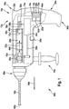
- FIG. 1 and FIG. 2 each show an embodiment of a hand tool 24a, 24b in a schematic representation with a hand tool device 10a, 10b according to the invention.
- a housing 32a, 32b of the power tool 24a, 24b shown broken so that the power tool device 10a, 10b in the interior of the power tool 24a, 24b is visible.
- FIG. 1 shows a handheld power tool device 10a with a percussion device 12a.
- the impact device 12a has an electric motor 34a, a crank mechanism 36a, a conversion element 38a, a drive piston 40a, a hammer tube 42a, a compression chamber 28a, a beater 44a, and a striker 46a.
- the electric motor 34a is rotatably connected to the crank mechanism 36a.
- the crank mechanism 36a converts a rotational movement of a shaft 50a of the electric motor 34a by means of the conversion element 38a into an oscillating linear movement 52a of the drive piston 40a along a main working direction 54a of the handheld power tool 24a.
- the drive piston 40a is guided by the hammer tube 42a.
- the hammer tube 42a surrounds the drive piston 40a in a circle.
- the driving piston 40a drives the racket 44a by means of a pressure of a gas, by means of air, in the compression chamber 28a.
- the beater 44a is disposed in the main working direction 54a in the hammer pipe 42a as viewed from the driving piston 40a and is also guided by the hammer pipe 42a.
- the racket 44a can, driven by the pressure, be moved between the drive piston 40a and the firing pin 46a. When the racket 44a hits the striker 46a, the racket 44a transmits a pulse to the striker 46a.
- the striker 46a is coupled to a tool 56a which is releasably disposed in a tool chuck 48a.
- the tool 56a is formed in this embodiment as a spiral drill bit. Other tools 56a that would appear meaningful to a person skilled in the art would also be possible.
- the electric motor 34a rotates the tool 56a about a rotation axis 60a by means of a shaft 58a.
- the rotation axis 60a is parallel to the main working direction 54a.
- Other configurations of the percussion mechanism that seem appropriate to a person skilled in the art, in particular for a percussion hammer, are possible.
- the impact device 12a has a control device 14a, which is intended to control two impact characteristics.
- the control device 14a is arranged, apart from two sensors 22a, 26a and a selector element 30a, together with power electronics 62a, which supply the electric motor 34a, on a circuit board 64a in a main handle-forming shaft 66a of the L-shaped housing 32a.
- the control device 14a has a computing unit 16a, which is designed as a microcontroller.
- the arithmetic unit 16a executes three routines during operation.
- a first calculation routine 68a is provided to determine a feedback variable of the impact characteristics depending on a parameter.
- a pressure waveform in the compression chamber 28a and an acceleration course of the housing 32a serve as parameters.
- a second calculation routine 70a determines an operating point that serves as a control reference.
- a control routine 18a is provided to control the impact characteristic to be controlled with respect to the operating point.
- the control routine 18a has calculation methods not shown in more detail, e.g. for a PID controller and a comparison method.
- the regulating device 14a has a measuring device 20a which is provided to detect two parameters.
- the measuring device 20a has an acceleration sensor 22a.
- the acceleration sensor 22a is disposed on the board 64a coupled to the housing 32a.
- the acceleration parameter contains information about a Vibration of the housing 32 a and information about an energy that reflects a workpiece not shown in detail. The vibrations are measured by the position of the acceleration sensor 22a close to an operator, not shown.
- the measuring device 20a For detecting the pressure parameter in the compression chamber 28a of the impact device 12a, the measuring device 20a has a pressure sensor 26a.
- the pressure sensor 26a is arranged in an end face 72a of the drive piston 40a pointing in the main working direction 54a and is connected to the circuit board 64a by means of an information carrier, in this case an electrical line 74a. At this point, the pressure sensor 26a can permanently detect the pressure curve in the compression chamber 28a.
- the pressure parameter includes information about energy that reflects a workpiece and information about the vibration of the housing 32a.
- control device 14a has two control modes. Depending on the control mode, different operating points are used for the control. The different operating points are optimized for different effects. One of the control modes is intended to control to a vibration optimized operating point. The other control mode is intended to control an impact optimized operating point.
- the handheld power tool device 10a has the selection element 30a, which provides the operator with a choice of the control modes.
- the selection element 30a is designed as a switch and arranged on a lower side 76a of the housing 32a.
- FIG. 2 a further embodiment of the invention is shown.
- the letter a in the reference numerals of the embodiment in the FIG. 1 by the letter b in the reference numerals of the embodiment in the FIG. 2 replaced.
- the following description is essentially limited to the differences from the embodiment in FIG. 1 , wherein with respect to the same components, features and functions on the description of the embodiment in the FIG. 1 can be referenced.
- FIG. 12 shows a handheld power tool apparatus 10b in which a pressure sensor 26b, unlike the first embodiment, is disposed on a side 78b of a hammer tube 42b.
- the pressure sensor 26b is connected to a compression chamber 28b of the hammer tube 42b by means of a pressure passage 82b, the pressure passage 82b being disposed in a guide portion of the hammer tube 42b in which a beater 44b of a beater 12b is guided so that the beater 44b is at least at an operating point closes the pressure channel 82b and thus protects the pressure sensor 26b.
- the pressure channel 82b is arranged so far away from a drive piston 40b that the pressure sensor 26b is protected from the maximum of the pressure curve during a maximum of the pressure curve by a racket 44b.
- the maximum of the pressure curve occurs when a distance 80b between the beater 44b and the drive piston 40b is minimal.
- the beater 44b closes an opening 82b in the hammer tube 42b to the pressure sensor 26b.
- the drive piston 40b can also close the pressure channel 82b.
Landscapes
- Engineering & Computer Science (AREA)
- Mechanical Engineering (AREA)
- Percussive Tools And Related Accessories (AREA)
Description
- Die Erfindung geht aus von einer Handwerkzeugmaschinenvorrichtung nach dem Oberbegriff des Anspruchs 1. Eine solche Handwerkzeugmaschinenvorrichtung ist aus der
GB 2 411 375 A - Es ist bereits eine Handwerkzeugmaschinenvorrichtung mit zumindest einer Schlagvorrichtung vorgeschlagen worden.
- Die Erfindung geht aus von einer Handwerkzeugmaschinenvorrichtung mit zumindest einer Schlagvorrichtung. Erfindungsgemäß weist die Schlagvorrichtung eine Regelvorrichtung auf, die dazu vorgesehen ist, zumindest eine Schlagkenngröße bezogen auf die Vibration und die Schlagwirkung zu regeln. Unter einer "Schlagkenngröße" soll eine Wirkung eines Betriebs verstander werden, wobei die Regelvorrichtung insbesondere dazu vorgesehen ist, die Schlagkenngröße mittels einer Frequenzänderung der Schlagvorrichtung und/oder einer Drehzahländerung eines Motors zu regeln. Dabei kann der Motor von einem pneumatischen Motor oder besonders vorteilhaft von einem Elektromotor gebildet sein. Unter "vorgesehen" soll insbesondere speziell ausgestattet, ausgelegt und/oder programmiert verstanden werden. Durch die erfindungsgemäße Ausgestaltung der Handwerkzeugmaschinenvorrichtung kann mittels der Regelung der zumindest einen Schlagkenngröße die Schlagvorrichtung weitestgehend unabhängig von Eigenschaften eines Werkstücks optimiert werden.
- Des Weiteren weist die Regelvorrichtung erfindungsgemäß eine Recheneinheit auf, die zumindest dazu vorgesehen ist, abhängig von wenigstens einem Parameter zumindest eine Rückführgröße der Schlagkenngröße zu bestimmen. Unter einer "Recheneinheit" soll insbesondere ein Microcontroller mit einem Prozessor, einer Speichereinheit und mit einem in der Speichereinheit gespeicherten Betriebsprogramm und/oder in der Speichereinheit gespeicherten Berechnungsroutinen und/oder Regelroutinen verstanden werden. Unter einem "Parameter" soll in diesem Zusammenhang ein von inneren und/oder äußeren Einflüssen abhängiger, während eines Betriebs gemessener Wert und/oder Werteverlauf verstanden werden, der zumindest teilweise für die zumindest eine Schlagkenngröße beschreibend ist. Innere Einflüsse sind insbesondere eine Temperatur und/oder eine Schmierung von Teilen einer Handwerkzeugmaschine. Äußere Einflüsse sind insbesondere ein Werkzeug und/oder das Werkstück und/oder ein Bediener. Unter einer "Rückführgröße" soll in diesem Zusammenhang eine berechnete Information über die Schlagkenngröße verstanden werden, die zu einer Regelung der Schlagkenngröße verwendet werden kann. Durch die Bestimmung der Schlagkenngröße kann die Regelung verschiedene Parameter in die Regelung einbeziehen und besonders flexibel ausgelegt werden.
- Ferner weist die Regelvorrichtung erfindungsgemäß eine Regelroutine auf, die dazu vorgesehen ist, zumindest die Schlagkenngröße bezogen auf zumindest einen Arbeitspunkt zu regeln. Unter einer "Regelroutine" soll insbesondere eine Routine verstanden werden, die die zu einer Regelung während des Betriebs notwendigen Berechnungen ausführt und Ergebnisse ausgibt. Die Regelroutine läuft auf einer Recheneinheit. Unter einem "Arbeitspunkt" soll ein Betriebszustand verstanden werden, bei dem zumindest eine Schlagkenngröße in einem Betrieb auf einen vorgegebenen Werteverlauf geregelt wird. Der Arbeitspunkt weist vorzugsweise einen Sollverlauf und/oder einen Sollwert der Schlagkenngröße auf. Dadurch kann eine besonders leistungsfähige und/oder bedienerfreundliche Handwerkzeugmaschinenvorrichtung erreicht werden.
- Zudem weist die Regelvorrichtung erfindungsgemäß zumindest eine Messvorrichtung auf, wodurch die Regelvorrichtung und die Messvorrichtung vorteilhaft aufeinander abgestimmt werden können. Die Messvorrichtung ist dabei dazu vorgesehen, zumindest einen Parameter zu erfassen, in Abhängigkeit von dem die Rückführgröße der Schlagkenngröße bestimmt wird.
- Ferner weist die Messvorrichtung erfindungsgemäß zumindest einen Beschleunigungssensor auf, der dazu vorgesehen ist, zumindest einen Beschleunigungsparameter einer Handwerkzeugmaschine zu erfassen. Unter einem "Beschleunigungsparameter" soll ein gemessener Beschleunigungsverlauf in zumindest einer Achse verstanden werden, die parallel zu einer Hauptarbeitsrichtung liegt. Der Beschleunigungsparameter bildet insbesondere einen besonders genauen Parameter für eine Vibration der Handwerkzeugmaschine. Mittels des Beschleunigungssensors kann eine besonders vibrationsarme geregelte Handwerkzeugmaschine erreicht werden. Erfindungsgemäß weist die Messvorrichtung zumindest einen Drucksensor weiter auf, der dazu vorgesehen ist, einen Druckparameter in einer Kompressionskammer der Schlagvorrichtung zumindest zeitweise zu erfassen. Unter einem "Druckparameter" soll insbesondere ein gemessener relativer Druckverlauf in der Kompressionskammer verstanden werden. Der Druckparameter dient insbesondere dazu, eine Wirkung der von einem Werkstück reflektierten Energie besonders genau zu ermitteln. In diesem Zusammenhang soll unter "zumindest zeitweise" insbesondere verstanden werden, dass eine diskontinuierliche Erfassung des Drucks in der Kompressionskammer erfolgen kann. Vorzugsweise erfolgt zumindest eine Erfassung des Druckparameters zumindest in einem Zeitraum, wenn die Wirkung der Energie, die das Werkstück reflektiert, in der Kompressionskammer auftritt. Mittels des Drucksensors kann eine besonders wirkungsvoll arbeitende Handwerkzeugmaschine erreicht werden.
- Des Weiteren weist die Regelvorrichtung erfindungsgemäß zumindest zwei Regelmodi auf, die dazu vorgesehen sind, jeweils zumindest einen Arbeitspunkt bereitzustellen. Unter einem "Regelmodus" soll eine bestimmte Betriebsart verstanden werden, die eine Optimierung der Regelung auf zumindest eine bestimmte Wirkung zum Ziel hat. Der Arbeitspunkt wird insbesondere von einer Berechnungsroutine auf Grundlage des Regelmodus bestimmt. Dadurch kann eine auf verschiedene Wirkung optimierte Regelung erreicht werden.
- Ferner ist die Regelvorrichtung erfindungsgemäß in einem der Regelmodi dazu vorgesehen, auf einen vibrationsoptimierten Arbeitspunkt zu regeln. Unter "vibrationsoptimiert" soll eine in einem Betrieb objektiv und/oder auch subjektiv vibrationsarme Handwerkzeugmaschine verstanden werden. Dabei kann insbesondere eine Regelung auf eine energiearme Vibration und/oder auf eine von einem Bediener als weniger unangenehm empfundene Vibration optimiert sein. Dadurch kann dem Bediener ein besonders komfortables Arbeiten ermöglichen werden.
- Zudem ist die Regelvorrichtung erfindungsgemäß in einem der Regelmodi dazu vorgesehen, auf einen schlagoptimierten Arbeitspunkt zu regeln. Unter "schlagoptimiert" soll verstanden werden, dass die Handwerkzeugmaschine in einem Betrieb eine größtmögliche Leistungsfähigkeit erreicht. Mittels des schlagoptimierten Arbeitspunkts kann ein besonders wirkungsvolles Arbeiten erreicht werden.
Des Weiteren wird ein Auswahlelement vorgeschlagen, das dem Bediener eine Auswahlmöglichkeit des Regelmodus bereitstellt, wodurch der Bediener komfortabel zwischen verschiedenen Regelmodi wechseln kann.
Ferner geht die Erfindung von einer Handwerkzeugmaschine mit einer Handwerkzeugmaschinenvorrichtung aus, wobei sämtliche, dem Fachmann als sinnvoll erscheinende Handwerkzeugmaschinen mit einer Schlagvorrichtung, wie insbesondere Schlagbohrmaschinen, Bohrhämmer, Schlagbohrschrauber, Drehschlagschrauber, Schlagschrauber, Schlaghämmer, Abbruchhämmer und/oder Multifunktionswerkzeuge, zum Betreiben mit der Handwerkzeugmaschinenvorrichtung denkbar wären, wodurch eine besonders wirkungsvolle und/oder komfortabel einsetzbare Handwerkzeugmaschine bereitgestellt werden kann.
Weitere Vorteile ergeben sich aus der folgenden Zeichnungsbeschreibung. In der Zeichnung sind Ausführungsbeispiele der Erfindung dargestellt. Die Zeichnung, die Beschreibung und die Ansprüche enthalten zahlreiche Merkmale in Kombination. Der Fachmann wird die Merkmale zweckmäßigerweise auch einzeln betrachten und zu sinnvollen weiteren Kombinationen im Rahmen der Ansprüche zusammenfassen. - Es zeigen:
- Fig. 1
- eine Handwerkzeugmaschine mit einer Handwerkzeugmaschinenvorrichtung, einem Drucksensor und einem Beschleunigungssensor und
- Fig. 2
- eine alternative Anordnung des Drucksensors.
-
Figur 1 undFigur 2 zeigen jeweils ein Ausführungsbeispiel einer Handwerkzeugmaschine 24a, 24b in einer schematischen Darstellung mit einer erfindungsgemäßen Handwerkzeugmaschinenvorrichtung 10a, 10b. Dabei ist ein Gehäuse 32a, 32b der Handwerkzeugmaschine 24a, 24b so gebrochen dargestellt, dass die Handwerkzeugmaschinenvorrichtung 10a, 10b im Inneren der Handwerkzeugmaschine 24a, 24b sichtbar ist. -
Figur 1 zeigt eine Handwerkzeugmaschinenvorrichtung 10a mit einer Schlagvorrichtung 12a. Die Schlagvorrichtung 12a weist einen Elektromotor 34a, einen Kurbeltrieb 36a, ein Umsetzelement 38a, einen Antriebskolben 40a, ein Hammerrohr 42a, eine Kompressionskammer 28a, einen Schläger 44a und einen Schlagbolzen 46a auf. Der Elektromotor 34a ist drehfest mit dem Kurbeltrieb 36a verbunden. Der Kurbeltrieb 36a wandelt eine Drehbewegung einer Welle 50a des Elektromotors 34a mit Hilfe des Umsetzelements 38a in eine oszillierende Linearbewegung 52a des Antriebskolbens 40a entlang einer Hauptarbeitsrichtung 54a der Handwerkzeugmaschine 24a um. Der Antriebskolben 40a wird von dem Hammerrohr 42a geführt. Dazu umschließt das Hammerrohr 42a den Antriebskolben 40a kreisförmig. Der Antriebskolben 40a treibt mittels eines Drucks eines Gases, und zwar mittels Luft, in der Kompressionskammer 28a den Schläger 44a an. Der Schläger 44a ist von dem Antriebskolben 40a her gesehen in Hauptarbeitsrichtung 54a in dem Hammerrohr 42a angeordnet und wird ebenfalls von dem Hammerrohr 42a geführt. Der Schläger 44a kann, von dem Druck getrieben, zwischen dem Antriebskolben 40a und dem Schlagbolzen 46a bewegt werden. Trifft der Schläger 44a auf den Schlagbolzen 46a, überträgt der Schläger 44a einen Impuls auf den Schlagbolzen 46a. Der Schlagbolzen 46a ist mit einem Werkzeug 56a gekoppelt, welches lösbar in einem Werkzeugfutter 48a angeordnet ist. Das Werkzeug 56a ist in diesem Ausführungsbeispiel als ein Spiralbohrmeißel ausgebildet. Es wären auch andere, einem Fachmann als sinnvoll erscheinende Werkzeuge 56a möglich. Zusätzlich dreht in diesem Ausführungsbeispiel der Elektromotor 34a mittels einer Welle 58a das Werkzeug 56a um eine Rotationsachse 60a. Die Rotationsachse 60a ist parallel zu der Hauptarbeitsrichtung 54a. Andere, einem Fachmann als sinnvoll erscheinende Konfigurationen des Schlagwerks, insbesondere für einen Schlaghammer, sind möglich. - Des Weiteren weist die Schlagvorrichtung 12a eine Regelvorrichtung 14a auf, die dazu vorgesehen ist, zwei Schlagkenngrößen zu regeln. Die Regelvorrichtung 14a ist bis auf zwei Sensoren 22a, 26a und ein Auswahlelement 30a zusammen mit einer Leistungselektronik 62a, die den Elektromotor 34a versorgt, auf einer Platine 64a in einem einen Haupthandgriff bildenden Schaft 66a des L-förmigen Gehäuses 32a angeordnet. Die Regelvorrichtung 14a weist eine Recheneinheit 16a auf, die als ein Mikrocontroller ausgebildet ist. Die Recheneinheit 16a führt im Betrieb drei Routinen aus. Eine erste Berechnungsroutine 68a ist dazu vorgesehen, abhängig von einem Parameter eine Rückführgröße der Schlagkenngrößen zu bestimmen. In diesem Ausführungsbeispiel dienen ein Druckverlauf in der Kompressionskammer 28a und ein Beschleunigungsverlauf des Gehäuses 32a als Parameter. Eine zweite Berechnungsroutine 70a bestimmt einen Arbeitspunkt, der als eine Führungsgröße der Regelung dient. Eine Regelroutine 18a ist dazu vorgesehen, die Schlagkenngröße, die geregelt werden soll, bezogen auf den Arbeitspunkt zu regeln. Dazu weist die Regelroutine 18a nicht näher dargestellte Berechnungsmethoden auf, z.B. für einen PID-Regler und eine Vergleichsmethode.
- Ferner zeigt
Figur 1 , dass die Regelvorrichtung 14a eine Messvorrichtung 20a aufweist, die dazu vorgesehen ist, zwei Parameter zu erfassen. Zu einer Erfassung des Beschleunigungsparameters der Handwerkzeugmaschine 24a weist die Messvorrichtung 20a einen Beschleunigungssensor 22a auf. Der Beschleunigungssensor 22a ist auf der mit dem Gehäuse 32a gekoppelten Platine 64a angeordnet. Der Beschleunigungsparameter beinhaltet Informationen über eine Vibration des Gehäuses 32a und Informationen über eine Energie, die ein nicht näher dargestelltes Werkstück reflektiert. Die Vibrationen werden durch die Position des Beschleunigungssensors 22a nahe bei einem nicht näher dargestellten Bediener gemessen. - Zu einer Erfassung des Druckparameters in der Kompressionskammer 28a der Schlagvorrichtung 12a weist die Messvorrichtung 20a einen Drucksensor 26a auf. Der Drucksensor 26a ist in einer in Hauptarbeitsrichtung 54a weisenden Stirnseite 72a des Antriebskolbens 40a angeordnet und mittels eines Informationsträgers, in diesem Fall einer elektrischen Leitung 74a, mit der Platine 64a verbunden. An dieser Stelle kann der Drucksensor 26a den Druckverlauf in der Kompressionskammer 28a permanent erfassen. Der Druckparameter beinhaltet Informationen über eine Energie, die ein Werkstück reflektiert und Informationen über die Vibration des Gehäuses 32a.
- Ferner weist die Regelvorrichtung 14a zwei Regelmodi auf. Je nach Regelmodus werden unterschiedliche Arbeitspunkte für die Regelung verwendet. Die unterschiedlichen Arbeitspunkte sind auf unterschiedliche Wirkungen optimiert. Einer der Regelmodi ist dazu vorgesehen, auf einen vibrationsoptimierten Arbeitspunkt zu regeln. Der andere Regelmodus ist dazu vorgesehen, auf einen schlagoptimierten Arbeitspunkt zu regeln. Damit der Bediener die unterschiedlichen Regelmodi wählen kann, weist die Handwerkzeugmaschinenvorrichtung 10a das Auswahlelement 30a auf, das dem Bediener eine Auswahlmöglichkeit der Regelmodi bereitstellt. Das Auswahlelement 30a ist als ein Schalter ausgebildet und an einer Unterseite 76a des Gehäuses 32a angeordnet.
- In
Figur 2 ist ein weiteres Ausführungsbeispiel der Erfindung gezeigt. Zur Unterscheidung der Ausführungsbeispiele ist der Buchstabe a in den Bezugszeichen des Ausführungsbeispiels in derFigur 1 durch den Buchstaben b in den Bezugszeichen des Ausführungsbeispiels in derFigur 2 ersetzt. Die nachfolgende Beschreibung beschränkt sich im Wesentlichen auf die Unterschiede zu dem Ausführungsbeispiel inFigur 1 , wobei bezüglich gleich bleibender Bauteile, Merkmale und Funktionen auf die Beschreibung des Ausführungsbeispiels in derFigur 1 verwiesen werden kann. -
Figur 2 zeigt eine Handwerkzeugmaschinenvorrichtung 10b, bei der ein Drucksensor 26b im Unterschied zu dem ersten Ausführungsbeispiel an einer Seite 78b eines Hammerrohrs 42b angeordnet ist. Der Drucksensor 26b ist mittels eines Druckkanals 82b mit einer Kompressionskammer 28b des Hammerrohrs 42b verbunden, wobei der Druckkanal 82b in einem Führungsbereich des Hammerrohrs 42b angeordnet ist, in welchem ein Schläger 44b einer Schlagvorrichtung 12b geführt ist, so dass der Schläger 44b in zumindest einem Betriebspunkt den Druckkanal 82b verschließt und damit den Drucksensor 26b schützt. Dabei ist der Druckkanal 82b so weit von einem Antriebskolben 40b entfernt angeordnet, dass der Drucksensor 26b während eines Maximums des Druckverlaufs von einem Schläger 44b vor dem Maximum des Druckverlaufs geschützt ist. Das Maximum des Druckverlaufs tritt auf, wenn ein Abstand 80b zwischen dem Schläger 44b und dem Antriebskolben 40b minimal ist. Zu diesen Zeitpunkten verschließt der Schläger 44b eine Öffnung 82b in dem Hammerrohr 42b zu dem Drucksensor 26b. Alternativ zu dem Schläger 44b kann auch der Antriebskolben 40b den Druckkanal 82b verschließen.
Claims (3)
- Handwerkzeugmaschinenvorrichtung mit zumindest einer Schlagvorrichtung (12a, 12b), wobei die Schlagvorrichtung (12a, 12b) eine Regelvorrichtung (14a, 14b) aufweist, die dazu vorgesehen ist, zumindest eine Schlagkenngröße bezogen auf die Vibration und die Schlagwirkung zu regeln, wobei die Regelvorrichtung (14a, 14b) zumindest eine Messvorrichtung (20a, 20b) aufweist, die zumindest einen Beschleunigungssensor (22a, 22b) aufweist, der dazu vorgesehen ist, zumindest einen Beschleunigungsparameter einer Handwerkzeugmaschine (24a, 24b) zu erfassen, wobei der Beschleunigungsparameter von einem gemessenen Beschleunigungsverlauf in zumindest einer Achse gebildet ist, die parallel zu einer Hauptarbeitsrichtung der Handwerkzeugmaschine (24a, 24b) liegt, wobei die Regelvorrichtung (14a, 14b) eine Recheneinheit (16a, 16b) aufweist,
dadurch gekennzeichnet, dass die Messvorrichtung (20a, 20b) zumindest einen Drucksensor (26a, 26b) weiter aufweist, der dazu vorgesehen ist, einen Druckparameter in einer Kompressionskammer (28a, 28b) der Schlagvorrichtung (12a, 12b) zumindest zeitweise zu erfassen,
dass die Recheneinheit (16a, 16b) zumindest dazu vorgesehen ist, abhängig von mindestens der Beschleunigungsparameter und der Druckparameter zumindest eine Rückführgröße der Schlagkenngröße zu bestimmen,
und dass die Regelvorrichtung (14a, 14b) eine Regelroutine (18a, 18b) aufweist, die dazu vorgesehen ist, zumindest die Schlagkenngröße bezogen auf zumindest einen Arbeitspunkt zu regeln und die Regelvorrichtung (14a, 14b) zumindest zwei Regelmodi aufweist, die dazu vorgesehen sind, jeweils zumindest einen Arbeitspunkt bereitzustellen,
wobei die Regelvorrichtung (14a, 14b) in einem der Regelmodi dazu vorgesehen ist, auf einen vibrationsoptimierten Arbeitspunkt zu regeln und in einem der Regelmodi dazu vorgesehen ist, auf einen schlagoptimierten Arbeitspunkt zu regeln. - Handwerkzeugmaschinenvorrichtung zumindest nach Anspruch 1, gekennzeichnet durch ein Auswahlelement (30a, 30b), das einem Bediener eine Auswahlmöglichkeit des Regelmodus bereitstellt.
- Handwerkzeugmaschine mit einer Handwerkzeugmaschinenvorrichtung (10a, 10b) nach einem der Ansprüche 1 bis 2.
Applications Claiming Priority (1)
| Application Number | Priority Date | Filing Date | Title |
|---|---|---|---|
| DE102008044044A DE102008044044A1 (de) | 2008-11-25 | 2008-11-25 | Handwerkzeugmaschinenvorrichtung |
Publications (2)
| Publication Number | Publication Date |
|---|---|
| EP2189249A1 EP2189249A1 (de) | 2010-05-26 |
| EP2189249B1 true EP2189249B1 (de) | 2018-01-17 |
Family
ID=41278131
Family Applications (1)
| Application Number | Title | Priority Date | Filing Date |
|---|---|---|---|
| EP09171301.6A Not-in-force EP2189249B1 (de) | 2008-11-25 | 2009-09-25 | Handwerkzeugmaschinenvorrichtung und Handwerkzeugmaschine |
Country Status (3)
| Country | Link |
|---|---|
| EP (1) | EP2189249B1 (de) |
| CN (1) | CN101733735B (de) |
| DE (1) | DE102008044044A1 (de) |
Families Citing this family (16)
| Publication number | Priority date | Publication date | Assignee | Title |
|---|---|---|---|---|
| DE102012206451B4 (de) * | 2012-04-19 | 2020-12-10 | Hilti Aktiengesellschaft | Handwerkzeugmaschine |
| DE102012208870A1 (de) | 2012-05-25 | 2013-11-28 | Robert Bosch Gmbh | Schlagwerkeinheit |
| CN104334318A (zh) * | 2012-05-25 | 2015-02-04 | 罗伯特·博世有限公司 | 冲击机构单元 |
| CN103573183A (zh) * | 2012-08-06 | 2014-02-12 | 周飞 | 一种改进的气动冲击钻 |
| DE102013208902B4 (de) | 2013-05-14 | 2023-12-14 | Robert Bosch Gmbh | Handwerkzeugvorrichtung |
| DE102013212635B4 (de) * | 2013-06-28 | 2024-05-08 | Robert Bosch Gmbh | Handwerkzeugmaschine |
| DE102014207434A1 (de) * | 2014-04-17 | 2015-10-22 | Robert Bosch Gmbh | Verfahren zum Betreiben einer Handwerkzeugmaschine, Handwerkzeugmaschine |
| DE102014212253A1 (de) * | 2014-06-26 | 2015-12-31 | Robert Bosch Gmbh | Schlagwerkvorrichtung |
| EP3028821A1 (de) * | 2014-12-03 | 2016-06-08 | HILTI Aktiengesellschaft | Steuerungsverfahren für eine Handwerkzeugmaschine |
| EP3028820A1 (de) * | 2014-12-03 | 2016-06-08 | HILTI Aktiengesellschaft | Handwerkzeugmaschine und Steuerungsverfahren dafür |
| DE102015205172A1 (de) * | 2015-03-23 | 2016-09-29 | Robert Bosch Gmbh | Werkzeugmaschine, insbesondere Handwerkzeugmaschine, mit einer motorischen Antriebseinheit und mit zumindest einer Sensorvorrichtung |
| EP3290721A1 (de) | 2016-08-30 | 2018-03-07 | HILTI Aktiengesellschaft | Abstandssensor an ankerspitze |
| CN108637322A (zh) * | 2018-04-20 | 2018-10-12 | 李晓梅 | 一种数控加工设备 |
| CN108543979A (zh) * | 2018-04-20 | 2018-09-18 | 郑牡兰 | 一种先进的模具设计和制造技术设备 |
| CN108547471A (zh) * | 2018-04-20 | 2018-09-18 | 王云龙 | 一种安全消防组件 |
| CN110774236B (zh) * | 2019-11-20 | 2021-07-27 | 山东奥德燃气设备制造有限公司 | 一种压力可调的气动冲击工具 |
Family Cites Families (8)
| Publication number | Priority date | Publication date | Assignee | Title |
|---|---|---|---|---|
| DE2832169A1 (de) * | 1978-07-21 | 1980-01-31 | Hilti Ag | Motorisch betriebener bohrhammer |
| US6508315B1 (en) * | 2001-06-07 | 2003-01-21 | Steven James Lindsay | Small impact power tool |
| US6691798B1 (en) * | 2002-06-19 | 2004-02-17 | Steven James Lindsay | Variable hand pressure activated power tool |
| DE10309012B3 (de) * | 2003-03-01 | 2004-08-12 | Hilti Ag | Steuerverfahren einer axial schlagenden und drehenden Elektrohandwerkzeugmaschine |
| DE10316844A1 (de) * | 2003-04-11 | 2004-11-04 | Hilti Ag | Steuerung einer Elektrohandwerkzeugmaschine |
| GB2411375B (en) * | 2004-02-26 | 2008-04-09 | South West Highways Ltd | Vibration reduction system |
| DE102007000488A1 (de) * | 2007-09-12 | 2009-03-19 | Hilti Aktiengesellschaft | Handwerkzeugmaschine mit Luftfederschlagswerk, Linearmotor und Steuerverfahren |
| GB0804967D0 (en) * | 2008-03-18 | 2008-04-16 | Black & Decker Inc | Powered hammer with a vibration dampening mechanism |
-
2008
- 2008-11-25 DE DE102008044044A patent/DE102008044044A1/de not_active Withdrawn
-
2009
- 2009-09-25 EP EP09171301.6A patent/EP2189249B1/de not_active Not-in-force
- 2009-11-24 CN CN200910225001.5A patent/CN101733735B/zh not_active Expired - Fee Related
Non-Patent Citations (1)
| Title |
|---|
| None * |
Also Published As
| Publication number | Publication date |
|---|---|
| CN101733735A (zh) | 2010-06-16 |
| EP2189249A1 (de) | 2010-05-26 |
| CN101733735B (zh) | 2014-12-03 |
| DE102008044044A1 (de) | 2010-05-27 |
Similar Documents
| Publication | Publication Date | Title |
|---|---|---|
| EP2189249A1 (de) | Handwerkzeugmaschinenvorrichtung und Handwerkzeugmaschine | |
| EP2729280B1 (de) | Schlagwerkvorrichtung | |
| DE102013224759A1 (de) | Werkzeugmaschinenvorrichtung | |
| EP3056317B1 (de) | Handwerkzeugmaschine | |
| DE102009046789A1 (de) | Handwerkzeugmaschinenvorrichtung | |
| EP2855098B1 (de) | Schlagwerkeinheit | |
| EP2448715A1 (de) | Handwerkzeugmaschine | |
| DE102013212626B4 (de) | Handwerkzeugmaschinenvorrichtung | |
| DE102009027444A1 (de) | Handwerkzeugmaschine | |
| EP2364817A2 (de) | Bohrhammervorrichtung | |
| EP3068585A1 (de) | Handwerkzeugmaschine | |
| EP4377049A1 (de) | Verfahren zum steuern und regeln einer werkzeugmaschine | |
| DE10209293A1 (de) | Pneumatisches Schlagwerk | |
| DE102010001683A1 (de) | Handwerkzeugmaschinenvorrichtung | |
| DE102015006318A1 (de) | Kraftwerkzeug | |
| DE102016218775A1 (de) | Handwerkzeugmaschinensystem | |
| DE60103956T2 (de) | Schlagbohrmaschine | |
| EP3206839A1 (de) | MEIßELNDE HANDWERKZEUGMASCHINE | |
| DE102012208916A1 (de) | Schlagwerkeinheit | |
| EP4101595A1 (de) | Verfahren zur bestimmung einer eigenschaft eines werkzeugs sowie mobile werkzeugmaschine | |
| DE102010062450A1 (de) | Handwerkzeugmaschinenvorrichtung | |
| DE102016214844A1 (de) | Verfahren zu einem Betrieb einer tragbaren Werkzeugmaschine | |
| WO2012072326A1 (de) | Hammerschlagwerk | |
| DE102013212592A1 (de) | Handwerkzeugmaschinenschaltvorrichtung | |
| EP3808506A1 (de) | Handwerkzeugmaschine |
Legal Events
| Date | Code | Title | Description |
|---|---|---|---|
| PUAI | Public reference made under article 153(3) epc to a published international application that has entered the european phase |
Free format text: ORIGINAL CODE: 0009012 |
|
| AK | Designated contracting states |
Kind code of ref document: A1 Designated state(s): AT BE BG CH CY CZ DE DK EE ES FI FR GB GR HR HU IE IS IT LI LT LU LV MC MK MT NL NO PL PT RO SE SI SK SM TR |
|
| AX | Request for extension of the european patent |
Extension state: AL BA RS |
|
| 17P | Request for examination filed |
Effective date: 20101126 |
|
| 17Q | First examination report despatched |
Effective date: 20160209 |
|
| GRAP | Despatch of communication of intention to grant a patent |
Free format text: ORIGINAL CODE: EPIDOSNIGR1 |
|
| INTG | Intention to grant announced |
Effective date: 20170822 |
|
| RAP1 | Party data changed (applicant data changed or rights of an application transferred) |
Owner name: ROBERT BOSCH GMBH |
|
| GRAS | Grant fee paid |
Free format text: ORIGINAL CODE: EPIDOSNIGR3 |
|
| GRAA | (expected) grant |
Free format text: ORIGINAL CODE: 0009210 |
|
| AK | Designated contracting states |
Kind code of ref document: B1 Designated state(s): AT BE BG CH CY CZ DE DK EE ES FI FR GB GR HR HU IE IS IT LI LT LU LV MC MK MT NL NO PL PT RO SE SI SK SM TR |
|
| REG | Reference to a national code |
Ref country code: GB Ref legal event code: FG4D Free format text: NOT ENGLISH |
|
| REG | Reference to a national code |
Ref country code: CH Ref legal event code: EP |
|
| REG | Reference to a national code |
Ref country code: IE Ref legal event code: FG4D Free format text: LANGUAGE OF EP DOCUMENT: GERMAN |
|
| REG | Reference to a national code |
Ref country code: AT Ref legal event code: REF Ref document number: 964100 Country of ref document: AT Kind code of ref document: T Effective date: 20180215 |
|
| REG | Reference to a national code |
Ref country code: DE Ref legal event code: R096 Ref document number: 502009014678 Country of ref document: DE |
|
| REG | Reference to a national code |
Ref country code: NL Ref legal event code: MP Effective date: 20180117 |
|
| REG | Reference to a national code |
Ref country code: LT Ref legal event code: MG4D |
|
| PG25 | Lapsed in a contracting state [announced via postgrant information from national office to epo] |
Ref country code: NL Free format text: LAPSE BECAUSE OF FAILURE TO SUBMIT A TRANSLATION OF THE DESCRIPTION OR TO PAY THE FEE WITHIN THE PRESCRIBED TIME-LIMIT Effective date: 20180117 |
|
| PG25 | Lapsed in a contracting state [announced via postgrant information from national office to epo] |
Ref country code: ES Free format text: LAPSE BECAUSE OF FAILURE TO SUBMIT A TRANSLATION OF THE DESCRIPTION OR TO PAY THE FEE WITHIN THE PRESCRIBED TIME-LIMIT Effective date: 20180117 Ref country code: LT Free format text: LAPSE BECAUSE OF FAILURE TO SUBMIT A TRANSLATION OF THE DESCRIPTION OR TO PAY THE FEE WITHIN THE PRESCRIBED TIME-LIMIT Effective date: 20180117 Ref country code: NO Free format text: LAPSE BECAUSE OF FAILURE TO SUBMIT A TRANSLATION OF THE DESCRIPTION OR TO PAY THE FEE WITHIN THE PRESCRIBED TIME-LIMIT Effective date: 20180417 Ref country code: CY Free format text: LAPSE BECAUSE OF FAILURE TO SUBMIT A TRANSLATION OF THE DESCRIPTION OR TO PAY THE FEE WITHIN THE PRESCRIBED TIME-LIMIT Effective date: 20180117 Ref country code: HR Free format text: LAPSE BECAUSE OF FAILURE TO SUBMIT A TRANSLATION OF THE DESCRIPTION OR TO PAY THE FEE WITHIN THE PRESCRIBED TIME-LIMIT Effective date: 20180117 Ref country code: FI Free format text: LAPSE BECAUSE OF FAILURE TO SUBMIT A TRANSLATION OF THE DESCRIPTION OR TO PAY THE FEE WITHIN THE PRESCRIBED TIME-LIMIT Effective date: 20180117 |
|
| PG25 | Lapsed in a contracting state [announced via postgrant information from national office to epo] |
Ref country code: PL Free format text: LAPSE BECAUSE OF FAILURE TO SUBMIT A TRANSLATION OF THE DESCRIPTION OR TO PAY THE FEE WITHIN THE PRESCRIBED TIME-LIMIT Effective date: 20180117 Ref country code: GR Free format text: LAPSE BECAUSE OF FAILURE TO SUBMIT A TRANSLATION OF THE DESCRIPTION OR TO PAY THE FEE WITHIN THE PRESCRIBED TIME-LIMIT Effective date: 20180418 Ref country code: BG Free format text: LAPSE BECAUSE OF FAILURE TO SUBMIT A TRANSLATION OF THE DESCRIPTION OR TO PAY THE FEE WITHIN THE PRESCRIBED TIME-LIMIT Effective date: 20180417 Ref country code: LV Free format text: LAPSE BECAUSE OF FAILURE TO SUBMIT A TRANSLATION OF THE DESCRIPTION OR TO PAY THE FEE WITHIN THE PRESCRIBED TIME-LIMIT Effective date: 20180117 Ref country code: SE Free format text: LAPSE BECAUSE OF FAILURE TO SUBMIT A TRANSLATION OF THE DESCRIPTION OR TO PAY THE FEE WITHIN THE PRESCRIBED TIME-LIMIT Effective date: 20180117 Ref country code: IS Free format text: LAPSE BECAUSE OF FAILURE TO SUBMIT A TRANSLATION OF THE DESCRIPTION OR TO PAY THE FEE WITHIN THE PRESCRIBED TIME-LIMIT Effective date: 20180517 |
|
| REG | Reference to a national code |
Ref country code: FR Ref legal event code: PLFP Year of fee payment: 10 |
|
| PG25 | Lapsed in a contracting state [announced via postgrant information from national office to epo] |
Ref country code: MT Free format text: LAPSE BECAUSE OF FAILURE TO SUBMIT A TRANSLATION OF THE DESCRIPTION OR TO PAY THE FEE WITHIN THE PRESCRIBED TIME-LIMIT Effective date: 20180117 |
|
| REG | Reference to a national code |
Ref country code: DE Ref legal event code: R097 Ref document number: 502009014678 Country of ref document: DE |
|
| PG25 | Lapsed in a contracting state [announced via postgrant information from national office to epo] |
Ref country code: IT Free format text: LAPSE BECAUSE OF FAILURE TO SUBMIT A TRANSLATION OF THE DESCRIPTION OR TO PAY THE FEE WITHIN THE PRESCRIBED TIME-LIMIT Effective date: 20180117 Ref country code: RO Free format text: LAPSE BECAUSE OF FAILURE TO SUBMIT A TRANSLATION OF THE DESCRIPTION OR TO PAY THE FEE WITHIN THE PRESCRIBED TIME-LIMIT Effective date: 20180117 Ref country code: EE Free format text: LAPSE BECAUSE OF FAILURE TO SUBMIT A TRANSLATION OF THE DESCRIPTION OR TO PAY THE FEE WITHIN THE PRESCRIBED TIME-LIMIT Effective date: 20180117 |
|
| PLBE | No opposition filed within time limit |
Free format text: ORIGINAL CODE: 0009261 |
|
| STAA | Information on the status of an ep patent application or granted ep patent |
Free format text: STATUS: NO OPPOSITION FILED WITHIN TIME LIMIT |
|
| PG25 | Lapsed in a contracting state [announced via postgrant information from national office to epo] |
Ref country code: DK Free format text: LAPSE BECAUSE OF FAILURE TO SUBMIT A TRANSLATION OF THE DESCRIPTION OR TO PAY THE FEE WITHIN THE PRESCRIBED TIME-LIMIT Effective date: 20180117 Ref country code: SM Free format text: LAPSE BECAUSE OF FAILURE TO SUBMIT A TRANSLATION OF THE DESCRIPTION OR TO PAY THE FEE WITHIN THE PRESCRIBED TIME-LIMIT Effective date: 20180117 Ref country code: CZ Free format text: LAPSE BECAUSE OF FAILURE TO SUBMIT A TRANSLATION OF THE DESCRIPTION OR TO PAY THE FEE WITHIN THE PRESCRIBED TIME-LIMIT Effective date: 20180117 Ref country code: SK Free format text: LAPSE BECAUSE OF FAILURE TO SUBMIT A TRANSLATION OF THE DESCRIPTION OR TO PAY THE FEE WITHIN THE PRESCRIBED TIME-LIMIT Effective date: 20180117 |
|
| 26N | No opposition filed |
Effective date: 20181018 |
|
| PG25 | Lapsed in a contracting state [announced via postgrant information from national office to epo] |
Ref country code: SI Free format text: LAPSE BECAUSE OF FAILURE TO SUBMIT A TRANSLATION OF THE DESCRIPTION OR TO PAY THE FEE WITHIN THE PRESCRIBED TIME-LIMIT Effective date: 20180117 |
|
| PG25 | Lapsed in a contracting state [announced via postgrant information from national office to epo] |
Ref country code: MC Free format text: LAPSE BECAUSE OF FAILURE TO SUBMIT A TRANSLATION OF THE DESCRIPTION OR TO PAY THE FEE WITHIN THE PRESCRIBED TIME-LIMIT Effective date: 20180117 |
|
| REG | Reference to a national code |
Ref country code: BE Ref legal event code: MM Effective date: 20180930 |
|
| REG | Reference to a national code |
Ref country code: IE Ref legal event code: MM4A |
|
| PG25 | Lapsed in a contracting state [announced via postgrant information from national office to epo] |
Ref country code: LU Free format text: LAPSE BECAUSE OF NON-PAYMENT OF DUE FEES Effective date: 20180925 |
|
| PG25 | Lapsed in a contracting state [announced via postgrant information from national office to epo] |
Ref country code: IE Free format text: LAPSE BECAUSE OF NON-PAYMENT OF DUE FEES Effective date: 20180925 |
|
| PG25 | Lapsed in a contracting state [announced via postgrant information from national office to epo] |
Ref country code: BE Free format text: LAPSE BECAUSE OF NON-PAYMENT OF DUE FEES Effective date: 20180930 |
|
| PGFP | Annual fee paid to national office [announced via postgrant information from national office to epo] |
Ref country code: FR Payment date: 20190924 Year of fee payment: 11 |
|
| REG | Reference to a national code |
Ref country code: AT Ref legal event code: MM01 Ref document number: 964100 Country of ref document: AT Kind code of ref document: T Effective date: 20180925 |
|
| PGFP | Annual fee paid to national office [announced via postgrant information from national office to epo] |
Ref country code: GB Payment date: 20190924 Year of fee payment: 11 |
|
| PG25 | Lapsed in a contracting state [announced via postgrant information from national office to epo] |
Ref country code: AT Free format text: LAPSE BECAUSE OF NON-PAYMENT OF DUE FEES Effective date: 20180925 |
|
| PGFP | Annual fee paid to national office [announced via postgrant information from national office to epo] |
Ref country code: CH Payment date: 20190924 Year of fee payment: 11 |
|
| PG25 | Lapsed in a contracting state [announced via postgrant information from national office to epo] |
Ref country code: TR Free format text: LAPSE BECAUSE OF FAILURE TO SUBMIT A TRANSLATION OF THE DESCRIPTION OR TO PAY THE FEE WITHIN THE PRESCRIBED TIME-LIMIT Effective date: 20180117 |
|
| PG25 | Lapsed in a contracting state [announced via postgrant information from national office to epo] |
Ref country code: PT Free format text: LAPSE BECAUSE OF FAILURE TO SUBMIT A TRANSLATION OF THE DESCRIPTION OR TO PAY THE FEE WITHIN THE PRESCRIBED TIME-LIMIT Effective date: 20180117 Ref country code: HU Free format text: LAPSE BECAUSE OF FAILURE TO SUBMIT A TRANSLATION OF THE DESCRIPTION OR TO PAY THE FEE WITHIN THE PRESCRIBED TIME-LIMIT; INVALID AB INITIO Effective date: 20090925 |
|
| PG25 | Lapsed in a contracting state [announced via postgrant information from national office to epo] |
Ref country code: MK Free format text: LAPSE BECAUSE OF NON-PAYMENT OF DUE FEES Effective date: 20180117 |
|
| REG | Reference to a national code |
Ref country code: CH Ref legal event code: PL |
|
| GBPC | Gb: european patent ceased through non-payment of renewal fee |
Effective date: 20200925 |
|
| PG25 | Lapsed in a contracting state [announced via postgrant information from national office to epo] |
Ref country code: FR Free format text: LAPSE BECAUSE OF NON-PAYMENT OF DUE FEES Effective date: 20200930 |
|
| PG25 | Lapsed in a contracting state [announced via postgrant information from national office to epo] |
Ref country code: LI Free format text: LAPSE BECAUSE OF NON-PAYMENT OF DUE FEES Effective date: 20200930 Ref country code: GB Free format text: LAPSE BECAUSE OF NON-PAYMENT OF DUE FEES Effective date: 20200925 Ref country code: CH Free format text: LAPSE BECAUSE OF NON-PAYMENT OF DUE FEES Effective date: 20200930 |
|
| PGFP | Annual fee paid to national office [announced via postgrant information from national office to epo] |
Ref country code: DE Payment date: 20231124 Year of fee payment: 15 |
|
| REG | Reference to a national code |
Ref country code: DE Ref legal event code: R084 Ref document number: 502009014678 Country of ref document: DE |
|
| REG | Reference to a national code |
Ref country code: DE Ref legal event code: R119 Ref document number: 502009014678 Country of ref document: DE |
|
| PG25 | Lapsed in a contracting state [announced via postgrant information from national office to epo] |
Ref country code: DE Free format text: LAPSE BECAUSE OF NON-PAYMENT OF DUE FEES Effective date: 20250401 |