EP2188641B1 - Dispositif de mesure de l'intensite d'un courant electrique et appareil electrique comportant un tel dispositif - Google Patents
Dispositif de mesure de l'intensite d'un courant electrique et appareil electrique comportant un tel dispositif Download PDFInfo
- Publication number
- EP2188641B1 EP2188641B1 EP08807023A EP08807023A EP2188641B1 EP 2188641 B1 EP2188641 B1 EP 2188641B1 EP 08807023 A EP08807023 A EP 08807023A EP 08807023 A EP08807023 A EP 08807023A EP 2188641 B1 EP2188641 B1 EP 2188641B1
- Authority
- EP
- European Patent Office
- Prior art keywords
- coils
- conductor
- current
- electric
- magnetic circuit
- Prior art date
- Legal status (The legal status is an assumption and is not a legal conclusion. Google has not performed a legal analysis and makes no representation as to the accuracy of the status listed.)
- Active
Links
- 230000005291 magnetic effect Effects 0.000 claims abstract description 66
- 239000004020 conductor Substances 0.000 claims abstract description 48
- 238000005259 measurement Methods 0.000 claims abstract description 22
- 230000003071 parasitic effect Effects 0.000 claims abstract description 10
- 230000035699 permeability Effects 0.000 claims abstract description 5
- 238000004804 winding Methods 0.000 claims description 12
- 239000000758 substrate Substances 0.000 claims description 9
- 238000012545 processing Methods 0.000 claims description 8
- 239000003302 ferromagnetic material Substances 0.000 claims description 3
- 238000013461 design Methods 0.000 abstract description 2
- 239000003990 capacitor Substances 0.000 description 3
- 238000010276 construction Methods 0.000 description 3
- 230000006698 induction Effects 0.000 description 3
- 230000007935 neutral effect Effects 0.000 description 3
- XEEYBQQBJWHFJM-UHFFFAOYSA-N Iron Chemical compound [Fe] XEEYBQQBJWHFJM-UHFFFAOYSA-N 0.000 description 2
- PXHVJJICTQNCMI-UHFFFAOYSA-N Nickel Chemical compound [Ni] PXHVJJICTQNCMI-UHFFFAOYSA-N 0.000 description 2
- 230000000694 effects Effects 0.000 description 2
- 238000010616 electrical installation Methods 0.000 description 2
- 238000005516 engineering process Methods 0.000 description 2
- 238000004519 manufacturing process Methods 0.000 description 2
- 230000005355 Hall effect Effects 0.000 description 1
- 229910045601 alloy Inorganic materials 0.000 description 1
- 239000000956 alloy Substances 0.000 description 1
- 230000000295 complement effect Effects 0.000 description 1
- 230000001143 conditioned effect Effects 0.000 description 1
- 238000010411 cooking Methods 0.000 description 1
- 238000009826 distribution Methods 0.000 description 1
- 230000036039 immunity Effects 0.000 description 1
- 238000009776 industrial production Methods 0.000 description 1
- 229910052742 iron Inorganic materials 0.000 description 1
- 239000000696 magnetic material Substances 0.000 description 1
- 238000000034 method Methods 0.000 description 1
- 238000012986 modification Methods 0.000 description 1
- 230000004048 modification Effects 0.000 description 1
- 238000012544 monitoring process Methods 0.000 description 1
- 229910052759 nickel Inorganic materials 0.000 description 1
- 238000005457 optimization Methods 0.000 description 1
- 229920006395 saturated elastomer Polymers 0.000 description 1
- 230000035945 sensitivity Effects 0.000 description 1
- 238000011144 upstream manufacturing Methods 0.000 description 1
Images


Classifications
-
- G—PHYSICS
- G01—MEASURING; TESTING
- G01R—MEASURING ELECTRIC VARIABLES; MEASURING MAGNETIC VARIABLES
- G01R15/00—Details of measuring arrangements of the types provided for in groups G01R17/00 - G01R29/00, G01R33/00 - G01R33/26 or G01R35/00
- G01R15/14—Adaptations providing voltage or current isolation, e.g. for high-voltage or high-current networks
- G01R15/18—Adaptations providing voltage or current isolation, e.g. for high-voltage or high-current networks using inductive devices, e.g. transformers
- G01R15/181—Adaptations providing voltage or current isolation, e.g. for high-voltage or high-current networks using inductive devices, e.g. transformers using coils without a magnetic core, e.g. Rogowski coils
Definitions
- the present invention relates to a device for measuring the intensity of an electric current, comprising at least one magnetic circuit disposed near an electrical conductor traversed by a current to be measured in order to channel the induced magnetic field around this conductor by the current to be measured, at least one electrical coil associated with said magnetic circuit for providing a voltage proportional to the derivative of the intensity of the current to be measured, and at least one processing module of this voltage to deliver a value of the measured intensity.
- the invention also relates to an electrical apparatus equipped with such a device, this electrical device can be a switching device type switch, switch-switch, circuit breaker, or any other equivalent device, single-phase, polyphase, with or without neutral.
- This dynamics can be significantly improved by using a closed-loop configuration, where a compensation winding makes it possible to cancel the gap field, the current flowing through the compensation winding then being the image of the primary current.
- this type of sensor requires a relatively powerful power supply to be able to provide the compensation current.
- Rogowski principle which consists of a winding in the air placed around an electrical conductor through which a current to be measured passes, this winding being able to be formed of one or more electric coils connected in series.
- the absence of a magnetic core that can be saturated allows a large measurement dynamic.
- the industrial production of Rogowski coils of good quality is very complex, expensive and difficult to reproduce because these coils require a constant linear density of turns and a constant section of turns.
- the realization of an opening measuring device that is to say made in two parts to facilitate its establishment around an existing electrical conductor, is also delicate, the regularity of the winding being an essential element to the quality of such a device.
- Still other devices such as those described in the publications EP 0 438 616 and EP 1 450 176 provide a measurement of the intensity by a measurement of the point magnetic field in the narrow gap of a magnetic circuit of great thickness.
- DE 196 06 445 A1 and EP 1 074 846 show current sensors.
- the present invention aims to provide a solution to this problem by proposing a device for measuring the intensity of a current of simple design, economic, with a small footprint to integrate easily with any type of electrical appliances, providing a high measurement dynamics to be versatile and to measure as well as energy metering and / or overcurrent protection as required, this device being designed to be insensitive to spurious fields as well as to the position of the electrical conductor to be measured and to be realized in at least two parts facilitating its implementation.
- the invention relates to a measuring device as described in claim 1.
- the closed path has a substantially parallelogram shape
- the magnetic circuit is formed of two magnetic elements arranged on either side of the conductor and two coils arranged in the air gap of the magnetic elements of on both sides of this driver.
- the closed path may have a substantially polygonal shape
- the magnetic circuit is formed of a number N of magnetic elements arranged around said conductor and of a number N of coils arranged in the gap magnetic elements around this conductor.
- the coils are advantageously identical, mounted in opposition and electrically connected in series, so that their useful fields are added and their parasitic fields cancel each other out.
- Each coil is made in the form of a printed circuit.
- the coils of the coil are etched on the substrate of the printed circuit to form coils parallel to each other, each turn comprising at least one rectilinear and parallel upper and lower strand, at least one of the strands of each turn comprising an end section inclined with respect to said strand for connecting the turns to each other.
- the device may comprise means for measuring the voltage by a resistor or capacitor bridge mounted on the printed circuit used to make said coil.
- the magnetic circuit is made of ferromagnetic materials with high magnetic permeability, so that the magnetic field induced by the current to be measured is negligible in said magnetic circuit relative to the magnetic field in the coil or coils.
- This device advantageously comprises at least one support plate on which the magnetic circuit and the coils are mounted, this support plate comprising at least one opening for the passage of the conductor and at least one electrical connection circuit for connecting the coils to the module. treatment.
- this device is arranged to individually measure the intensity of the current flowing in several conductors and in this case comprises several identical measuring structures, each comprising at least one magnetic circuit and at least two electrical coils, the support plate being able to be common to all measurement structures.
- This measuring device may consist of a one-piece piece through which the conductor is threaded, or advantageously at least two parts assembled around the conductor during the introduction of the device in the electrical installation.
- the invention also relates to an electrical apparatus as described in claim 17.
- FIG. figure 1 The principle of the measuring device 1, according to the invention, for measuring the intensity 1 of a current flowing through an electrical conductor 2 or current line, hereinafter referred to as a conductor 2, is illustrated in FIG. figure 1 . It uses the magnetic field induced around the conductor 2 by the current I to be measured.
- the circulation of the lines of this magnetic field is controlled on a closed path C formed of at least one open magnetic circuit 3 and delimiting at least two gaps E closed by at least two electrical coils 4, called by the following coils 4, whose turns are oriented perpendicular to the direction of circulation of said field and occupy more than one third of the path C closed.
- the Ampère theorem is applied on path C by decomposing the field flowing in the air through the coils 4 and the field flowing in the magnetic circuit 3. If a magnetic circuit 3 having a high magnetic permeability is chosen, the component of the magnetic field flowing in this magnetic circuit is negligible compared with the component of the magnetic field. circulating in the coil 4. As a result, the voltage across the coil 4 is proportional to the derivative of the intensity I of the current to be measured. It is therefore the quality of the magnetic circuit 3 that will condition the performance of the measuring device 1.
- the magnetic circuit 3 is made of ferromagnetic materials with high magnetic permeability, such as iron-based alloys, nickel or the like.
- the magnetic circuit 3 is not used to focus the magnetic field, but to control the distribution of its field lines and limit the influence of this field in the areas not occupied by the coils 4.
- the magnetic circuit 3 is open and comprises two magnetic elements in the form of plates 30, planar or not, substantially parallel, arranged on either side of the conductor 2, separated by two air gaps E wide.
- the gaps S are referred to as "wide", as opposed to air gaps "narrow” known in the magnetic circuits usually used.
- These air gaps E each have a width at least greater than twice the thickness e of the plates 30 and are wide enough to accommodate the coils 4. They can have a size for example between 15 and 150mm, depending on the applications.
- This measuring device 1 also comprises two coils 4, substantially parallel, arranged on either side of the conductor 2, and extending inside each gap E between the two plates 30 to close the path C of the magnetic field without leaving any free space.
- the field lines circulate through coils 4 along a substantially rectilinear path C and perpendicular to the turns of said coils.
- These two coils 4 are electrically connected in series to deliver at their terminals an output voltage U (t) proportional to the derivative of the intensity I of the current to be measured.
- U (t) proportional to the derivative of the intensity I of the current to be measured.
- They are electrically identical, have the same number of turns and are wound in opposite directions for useful fields to be added and parasitic fields cancel each other out.
- the path C defined by this construction therefore has a substantially parallelogram shape.
- the sensitivity of the measuring device 1 to the parasitic fields and to the position of the electrical conductor 2 is conditioned by the ratio between the size of the useful surface of the coils 4, ie the number of turns multiplied by the surface of each turn, and the size stray surfaces, in particular the surface of the return loops.
- the coils 4 made on printed circuits are particularly suitable for this application. This technology indeed allows a very good control of the geometry and the regularity of the winding, and considerably reduces the parasitic surfaces at the level of the return loops, thanks to the fineness of engraving which allows the realization of tracks distant from 0.1mm to 0.2 mm.
- the immunity to the parasitic fields is obtained by the construction and arrangement of the coils 4, it is possible to substantially reduce the section of the magnetic circuit 3, thus the overall size of the measuring device 1. Moreover, the presence an air gap E wide also makes the measuring device 1 less sensitive to dimensional variations of this gap E.
- the gap E wide has the effect of limiting the induction in the magnetic material and therefore allows an extended measurement dynamic compared to current solutions narrow gap is obtained a measurement device 1 having a great dynamic of which, for example, extends from 1A to 1600A for a given rating from 63A to 160A, which allows combined applications of measurement, protection and energy metering.
- the construction as defined above makes it possible to easily produce very compact and compact measuring devices 1 that can be integrated perfectly into or on an electrical apparatus 10, an example of which is given with reference to Figures 2 to 4 . According to the needs, it is possible to propose the measuring devices 1 in a one-piece version (in one piece) in which the conductors 2 must be threaded, and in a demountable version (in two pieces at least) facilitating its assembly on existing drivers 2.
- the measuring device 1 is completed by a processing module (not shown) of the output voltage U (t) of the coils 4 in order to deliver a value of the intensity I measured.
- this processing module is an integrator, to which can be added a phase compensation stage with a capacitive link to suppress the output offset and the noise, in order to improve its stability.
- This processing module or any other equivalent module is not the subject of the present invention and will not be detailed.
- the measuring device 1 can also be completed by a means for measuring the voltage 7 across a resistor bridge 71 or capacitors mounted on a printed circuit 40 used for producing the coils 4 as explained more far.
- a combined intensity / voltage sensor is thus obtained with the same measurement device 1 (see dashed representation on FIG. Figure 7B ) for measuring the intensity of the current flowing through the electrical conductor 2 and simultaneously the voltage of the conductor, for example for the purpose of producing an energy meter, a power transducer or a combined current / voltage control apparatus used in monitoring of electrical networks.
- the bridge of resistors 71 or capacitors is connected by connection pads 72 of a side to the processing module (not shown) via the support plate 5 and the other side to the conductor 2 itself by a wire connection (not shown) or the like.
- the measuring device 1 may comprise an open magnetic circuit 3 having other shapes, with several gaps E , each gap being closed by a coil 4, and defining a polygonal path C .
- the Figures 3 to 4 illustrate a preferred example of the measuring device 1 according to the invention, arranged to be mounted in an electrical apparatus 10, as shown in FIG. figure 2 .
- This electrical apparatus 10 may be an electrical switching device such as a switch, a switch-switch, a circuit breaker or the like, mono or polyphase, with or without neutral.
- the electrical apparatus 10 comprises four conductors 2, including three phases and a neutral.
- the gap A between two consecutive conductors 2 is relatively small; for example between 15 and 50mm, depending on the type of device, which leaves can of volume available to place a measuring device 1 on each electrical conductor 2.
- the height H available is limited by the connection constraints of conductors 2 to different circuits or electrical devices upstream and / or downstream, and is for example between 30 and 80mm.
- the measuring device 1 mounted on the electrical apparatus 10 comprises as many identical measurement structures 1 'as conductors 2.
- Each measurement structure 1' has around each conductor 2 a closed path C for the circulation of the magnetic field lines. consisting of two parallel plates 30 and two coils 4 arranged in the gap E , according to the principle illustrated in FIG. figure 1 .
- Each measuring structure 1 ' is mounted on a support plate 5, which comprises electrical connection circuits (not shown) allowing connect the coils 4 to the processing module (not shown).
- This support plate 5 has openings 50 forming passages for each conductor 2.
- This measuring device 1 is housed in an insulating housing 6.
- each coil 4 is made in the form of a printed circuit 40. It comprises turns 41 parallel to each other and orthogonal to the path C taken by the magnetic field lines induced by the current to be measured.
- the two electric coils 4 are opposite and connected in series, as explained above.
- the substrate used to produce the printed circuits 40 has a small thickness, of the order of 1 to 3 mm. The thickness of the substrate is chosen so as to maximize the ratio between the linear density of the turns and this thickness, which is for example equal to 1.6 mm for a printed circuit made with standard technology.
- FIG. figure 6 An example of a drawing of the coil winding 41 is illustrated in FIG. figure 6 , in enlarged mode and voluntarily disproportionate, to facilitate comprehension.
- Each turn 41 etched on the substrate comprises an upper straight strand 41a, a first return loop 41b passing through the substrate through a first connection hole 43 perpendicular to the substrate, a straight lower strand 41c parallel to the upper strand 41a, and a second feedback loop 41d passing through the substrate through a second connection hole 43 perpendicular to the substrate.
- the upper strand 41a of each turn has an inclined end portion 41e with respect to said strand, to start its return loop 41d in the neighboring connecting hole 43, and thus to subsequently, the inclined end sections 41e being parallel to each other.
- other equivalent drawings may also be suitable.
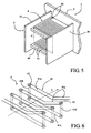
- FIGS. 7A, 7B and 7C illustrate an "opening" version of the measuring device 1 according to the invention, to be able to be mounted on the electrical conductors 3 by interlocking and not by threading, when setting up the device in the electrical installation.
- the configuration of the magnetic circuits 3 is reversed: the plates 30 are parallel to the support plate 5, and the coils 4 perpendicular to this plate.
- the support plate 5 carries a first set of plates 30 as well as the coils 4 which are directly connected to each other and to the electrical connection circuits provided on this plate 5.
- This measuring device 1 can be opened without any difficulty. It suffices that the second set of plates 30, opposite to the support plate 5, is mounted on a movable or removable part of the housing 6.
Landscapes
- Engineering & Computer Science (AREA)
- Power Engineering (AREA)
- Physics & Mathematics (AREA)
- General Physics & Mathematics (AREA)
- Measuring Instrument Details And Bridges, And Automatic Balancing Devices (AREA)
- Measurement Of Current Or Voltage (AREA)
- Electron Sources, Ion Sources (AREA)
- Electrical Discharge Machining, Electrochemical Machining, And Combined Machining (AREA)
Priority Applications (2)
| Application Number | Priority Date | Filing Date | Title |
|---|---|---|---|
| SI200830277T SI2188641T1 (sl) | 2007-09-10 | 2008-09-09 | Naprava za merjenje intenzitete električnega toka in električni aparat, obsegajoč tovrstno napravo |
| PL08807023T PL2188641T3 (pl) | 2007-09-10 | 2008-09-09 | Układ do pomiaru natężenia prądu elektrycznego oraz urządzenie elektryczne zawierające taki układ |
Applications Claiming Priority (2)
| Application Number | Priority Date | Filing Date | Title |
|---|---|---|---|
| FR0706309A FR2920881B1 (fr) | 2007-09-10 | 2007-09-10 | DISPOSITIF DE MESURE DE l'INTENSITE D'UN COURANT ELECTRIQUE ET APPAREIL ELECTRIQUE COMPORTANT UN TEL DISPOSITIF. |
| PCT/IB2008/002332 WO2009034440A2 (fr) | 2007-09-10 | 2008-09-09 | Dispositif de mesure de l'intensite d'un courant electrique et appareil electrique comportant un tel dispositif |
Publications (2)
| Publication Number | Publication Date |
|---|---|
| EP2188641A2 EP2188641A2 (fr) | 2010-05-26 |
| EP2188641B1 true EP2188641B1 (fr) | 2011-03-23 |
Family
ID=39323710
Family Applications (1)
| Application Number | Title | Priority Date | Filing Date |
|---|---|---|---|
| EP08807023A Active EP2188641B1 (fr) | 2007-09-10 | 2008-09-09 | Dispositif de mesure de l'intensite d'un courant electrique et appareil electrique comportant un tel dispositif |
Country Status (12)
| Country | Link |
|---|---|
| US (1) | US8299779B2 (ja) |
| EP (1) | EP2188641B1 (ja) |
| JP (1) | JP2010539451A (ja) |
| CN (1) | CN101802623A (ja) |
| AT (1) | ATE503188T1 (ja) |
| DE (1) | DE602008005762D1 (ja) |
| DK (1) | DK2188641T3 (ja) |
| ES (1) | ES2363840T3 (ja) |
| FR (1) | FR2920881B1 (ja) |
| PL (1) | PL2188641T3 (ja) |
| SI (1) | SI2188641T1 (ja) |
| WO (1) | WO2009034440A2 (ja) |
Families Citing this family (17)
| Publication number | Priority date | Publication date | Assignee | Title |
|---|---|---|---|---|
| JP2010256141A (ja) * | 2009-04-23 | 2010-11-11 | Toshiba Toko Meter Systems Co Ltd | 電流検出装置およびこれを用いた電力量計 |
| JP5680287B2 (ja) * | 2009-05-27 | 2015-03-04 | 新科實業有限公司SAE Magnetics(H.K.)Ltd. | 電流センサ |
| US9664711B2 (en) | 2009-07-31 | 2017-05-30 | Pulse Electronics, Inc. | Current sensing devices and methods |
| US9823274B2 (en) | 2009-07-31 | 2017-11-21 | Pulse Electronics, Inc. | Current sensing inductive devices |
| JP5614967B2 (ja) * | 2009-10-22 | 2014-10-29 | 東光東芝メーターシステムズ株式会社 | 電流検出装置およびこれを用いた電力量計 |
| JP5820164B2 (ja) | 2011-07-01 | 2015-11-24 | 東光東芝メーターシステムズ株式会社 | 電流検出装置およびこれを用いた電力量計 |
| JP5869785B2 (ja) * | 2011-07-01 | 2016-02-24 | 東光東芝メーターシステムズ株式会社 | 電流検出装置及び電力量計 |
| US9304149B2 (en) * | 2012-05-31 | 2016-04-05 | Pulse Electronics, Inc. | Current sensing devices and methods |
| ES2659190T3 (es) * | 2013-04-02 | 2018-03-14 | Arteche Centro De Tecnología, A.I.E. | Sensor de corriente basado en una bobina de Rogowski |
| EP2853904A1 (en) * | 2013-09-30 | 2015-04-01 | LEM Intellectual Property SA | Clip-on current transducer or current transformer |
| GB2526579A (en) | 2014-05-28 | 2015-12-02 | Eaton Ind Netherlands Bv | Sensor for measuring current in a conductor |
| GB201518372D0 (en) * | 2015-10-16 | 2015-12-02 | Johnson Electric Sa | Current determining device and methods |
| FR3053795B1 (fr) * | 2016-07-08 | 2019-11-08 | Schneider Electric Industries Sas | Appareil de mesure de courants electriques dans des conducteurs electriques |
| FR3086793B1 (fr) | 2018-09-27 | 2020-09-11 | Schneider Electric Ind Sas | Transformateur de courant electrique et appareil de mesure de courant |
| JP2020148640A (ja) * | 2019-03-14 | 2020-09-17 | 株式会社東芝 | 電流検出装置 |
| FR3132953A1 (fr) * | 2022-02-24 | 2023-08-25 | Omegawatt | Système de fermeture magnétique pour boucle Rogowski |
| US11994541B2 (en) * | 2022-04-15 | 2024-05-28 | Allegro Microsystems, Llc | Current sensor assemblies for low currents |
Family Cites Families (21)
| Publication number | Priority date | Publication date | Assignee | Title |
|---|---|---|---|---|
| US4980794A (en) * | 1987-02-19 | 1990-12-25 | Westinghouse Electric Corp. | Electromagnetic contactor with lightweight wide range current transducer with sintered powdered metal core |
| ATE104774T1 (de) * | 1990-01-23 | 1994-05-15 | Siemens Ag | Strom-spannungswandler fuer elektronische haushaltszaehler. |
| FR2678069A1 (fr) * | 1991-06-18 | 1992-12-24 | Commissariat Energie Atomique | Capteur de courant utilisant un magnetometre directionnel a resonance. |
| FR2692074B1 (fr) * | 1992-06-05 | 1994-07-22 | Alsthom Gec | Bobine de rogowski. |
| US5430613A (en) * | 1993-06-01 | 1995-07-04 | Eaton Corporation | Current transformer using a laminated toroidal core structure and a lead frame |
| US5453681A (en) * | 1993-07-06 | 1995-09-26 | General Electric Company | Current sensor employing a mutually inductive current sensing scheme |
| CH690464A5 (fr) | 1995-02-23 | 2000-09-15 | Lem Liaisons Electron Mec | Dispositif de mesure inductif pour la mesure de composantes de courant alternatif superposées à un courant fort continu. |
| US6043641A (en) * | 1998-02-17 | 2000-03-28 | Singer; Jerome R. | Method and apparatus for rapid determinations of voltage and current in wires and conductors |
| JP2000021661A (ja) * | 1998-06-30 | 2000-01-21 | Omron Corp | Ct型電流センサ |
| US6380727B1 (en) * | 1998-07-03 | 2002-04-30 | Ascom Energy Systems Ag | Current sensor |
| DE60033344T2 (de) * | 1999-08-04 | 2007-07-19 | Schneider Electric Industries Sas | Stromsensor für eine elektrische Vorrichtung |
| US7109838B2 (en) * | 2000-09-08 | 2006-09-19 | Texas Instruments Incorporated | System for integrating a toroidal inductor in a semiconductor device |
| JP2003130894A (ja) * | 2001-10-29 | 2003-05-08 | Toshiba Corp | 変流器 |
| US6680608B2 (en) * | 2002-02-27 | 2004-01-20 | Mcgraw-Edison Company | Measuring current through an electrical conductor |
| JP2003315373A (ja) * | 2002-04-18 | 2003-11-06 | Toshiba Corp | 電流検出装置及び半導体装置 |
| EP1450176A1 (en) * | 2003-02-21 | 2004-08-25 | Liaisons Electroniques-Mecaniques Lem S.A. | Magnetic field sensor and electrical current sensor therewith |
| DE102004021495A1 (de) * | 2004-04-30 | 2005-11-24 | Vacuumschmelze Gmbh & Co. Kg | Stromsensor |
| US7227442B2 (en) * | 2005-04-01 | 2007-06-05 | Schweitzer Engineering Laboratories, Inc. | Precision printed circuit board based rogowski coil and method for manufacturing same |
| JP4674533B2 (ja) * | 2005-12-02 | 2011-04-20 | パナソニック電工株式会社 | 交流電流検出用コイル |
| US7532000B2 (en) * | 2006-08-03 | 2009-05-12 | The Boeing Company | Method and system for measurement of current flows in fastener arrays |
| US7538541B2 (en) * | 2006-11-06 | 2009-05-26 | Cooper Technologies Company | Split Rogowski coil current measuring device and methods |
-
2007
- 2007-09-10 FR FR0706309A patent/FR2920881B1/fr not_active Expired - Fee Related
-
2008
- 2008-09-09 DK DK08807023.0T patent/DK2188641T3/da active
- 2008-09-09 US US12/676,751 patent/US8299779B2/en active Active
- 2008-09-09 AT AT08807023T patent/ATE503188T1/de active
- 2008-09-09 PL PL08807023T patent/PL2188641T3/pl unknown
- 2008-09-09 WO PCT/IB2008/002332 patent/WO2009034440A2/fr active Application Filing
- 2008-09-09 EP EP08807023A patent/EP2188641B1/fr active Active
- 2008-09-09 JP JP2010523605A patent/JP2010539451A/ja active Pending
- 2008-09-09 ES ES08807023T patent/ES2363840T3/es active Active
- 2008-09-09 SI SI200830277T patent/SI2188641T1/sl unknown
- 2008-09-09 DE DE602008005762T patent/DE602008005762D1/de active Active
- 2008-09-09 CN CN200880106253A patent/CN101802623A/zh active Pending
Also Published As
| Publication number | Publication date |
|---|---|
| DK2188641T3 (da) | 2011-07-11 |
| WO2009034440A3 (fr) | 2009-05-22 |
| EP2188641A2 (fr) | 2010-05-26 |
| CN101802623A (zh) | 2010-08-11 |
| PL2188641T3 (pl) | 2011-10-31 |
| FR2920881A1 (fr) | 2009-03-13 |
| JP2010539451A (ja) | 2010-12-16 |
| US8299779B2 (en) | 2012-10-30 |
| FR2920881B1 (fr) | 2010-03-05 |
| DE602008005762D1 (de) | 2011-05-05 |
| ES2363840T3 (es) | 2011-08-17 |
| SI2188641T1 (sl) | 2011-08-31 |
| ATE503188T1 (de) | 2011-04-15 |
| US20100301836A1 (en) | 2010-12-02 |
| WO2009034440A2 (fr) | 2009-03-19 |
Similar Documents
| Publication | Publication Date | Title |
|---|---|---|
| EP2188641B1 (fr) | Dispositif de mesure de l'intensite d'un courant electrique et appareil electrique comportant un tel dispositif | |
| EP3171182B1 (fr) | Capteur de courant et dispositif pour la mesure d'un courant électrique | |
| EP1596206B1 (fr) | Dispositif de mesure d'un courant électrique, capteur de courant, déclencheur électrique et dispositif de coupure comportant un tel dispositif de mesure | |
| EP1074846A2 (fr) | Capteur de courant pour appareil électrique | |
| FR2752302A1 (fr) | Capteur de champ magnetique a pont de magnetoresistances | |
| EP3268754B1 (fr) | Capteur de courant pour mesurer un courant alternatif | |
| EP1736784A1 (fr) | Dispositif de mesure de courant differentiel, module de declenchement et dispositif de coupure | |
| FR2750769A1 (fr) | Capteur de champ magnetique en couche mince | |
| FR2660751A1 (fr) | Capteur pour la mesure du deplacement relatif transversal d'une piece conductrice de forme allongee. | |
| CH679710A5 (ja) | ||
| FR2727209A1 (fr) | Detecteur de courant alternatif a geometrie de plaques paralleles et auto-alimentation | |
| EP3748370B1 (fr) | Capteurs de courant et systèmes de mesure associés | |
| EP2761309A1 (fr) | Capteur de courant sans contact | |
| CA2837564C (fr) | Procede et systeme de controle de l'instant de mise sous tension d'un dispositif comprenant un circuit magnetique | |
| EP0359886A1 (fr) | Dispositif de mesure de courants forts | |
| FR2827962A1 (fr) | Dispositif de mesure a effet hall de l'intensite d'un courant electrique | |
| CA2183265A1 (fr) | Capteur de courant et appareil electrique le comportant | |
| FR2755532A1 (fr) | Transformateur de courant, declencheur et disjoncteur comportant un tel transformateur | |
| EP3470856A1 (fr) | Module de détection d'un défaut électrique pour un ensemble de protection électrique et ensemble de protection électrique comprenant un tel module de détection | |
| FR2925756A1 (fr) | Appareil de protection electrique modulaire comportant une fonction electrique complementaire telle la fonction protection differentielle | |
| EP1936389B1 (fr) | Capteur inductif de mesure de courant | |
| EP0622635A1 (fr) | Capteur de courant pour courants alternatifs | |
| EP3629347B1 (fr) | Transformateur de courant electrique et appareil de mesure de courant | |
| FR2891946A1 (fr) | Dispositif ouvrant de mesure d'un courant electrique | |
| FR2896882A1 (fr) | Detecteur electromagnetique de vitesse de rotation d'un organe tournant |
Legal Events
| Date | Code | Title | Description |
|---|---|---|---|
| PUAI | Public reference made under article 153(3) epc to a published international application that has entered the european phase |
Free format text: ORIGINAL CODE: 0009012 |
|
| 17P | Request for examination filed |
Effective date: 20100303 |
|
| AK | Designated contracting states |
Kind code of ref document: A2 Designated state(s): AT BE BG CH CY CZ DE DK EE ES FI FR GB GR HR HU IE IS IT LI LT LU LV MC MT NL NO PL PT RO SE SI SK TR |
|
| AX | Request for extension of the european patent |
Extension state: AL BA MK RS |
|
| GRAP | Despatch of communication of intention to grant a patent |
Free format text: ORIGINAL CODE: EPIDOSNIGR1 |
|
| DAX | Request for extension of the european patent (deleted) | ||
| GRAS | Grant fee paid |
Free format text: ORIGINAL CODE: EPIDOSNIGR3 |
|
| GRAA | (expected) grant |
Free format text: ORIGINAL CODE: 0009210 |
|
| AK | Designated contracting states |
Kind code of ref document: B1 Designated state(s): AT BE BG CH CY CZ DE DK EE ES FI FR GB GR HR HU IE IS IT LI LT LU LV MC MT NL NO PL PT RO SE SI SK TR |
|
| REG | Reference to a national code |
Ref country code: GB Ref legal event code: FG4D Free format text: NOT ENGLISH |
|
| REG | Reference to a national code |
Ref country code: CH Ref legal event code: EP |
|
| REG | Reference to a national code |
Ref country code: IE Ref legal event code: FG4D |
|
| REF | Corresponds to: |
Ref document number: 602008005762 Country of ref document: DE Date of ref document: 20110505 Kind code of ref document: P |
|
| REG | Reference to a national code |
Ref country code: DE Ref legal event code: R096 Ref document number: 602008005762 Country of ref document: DE Effective date: 20110505 |
|
| REG | Reference to a national code |
Ref country code: CH Ref legal event code: NV Representative=s name: CABINET ROLAND NITHARDT CONSEILS EN PROPRIETE INDU |
|
| REG | Reference to a national code |
Ref country code: DK Ref legal event code: T3 |
|
| REG | Reference to a national code |
Ref country code: NL Ref legal event code: VDEP Effective date: 20110323 |
|
| REG | Reference to a national code |
Ref country code: SE Ref legal event code: TRGR |
|
| PG25 | Lapsed in a contracting state [announced via postgrant information from national office to epo] |
Ref country code: HR Free format text: LAPSE BECAUSE OF FAILURE TO SUBMIT A TRANSLATION OF THE DESCRIPTION OR TO PAY THE FEE WITHIN THE PRESCRIBED TIME-LIMIT Effective date: 20110323 Ref country code: LT Free format text: LAPSE BECAUSE OF FAILURE TO SUBMIT A TRANSLATION OF THE DESCRIPTION OR TO PAY THE FEE WITHIN THE PRESCRIBED TIME-LIMIT Effective date: 20110323 Ref country code: LV Free format text: LAPSE BECAUSE OF FAILURE TO SUBMIT A TRANSLATION OF THE DESCRIPTION OR TO PAY THE FEE WITHIN THE PRESCRIBED TIME-LIMIT Effective date: 20110323 Ref country code: GR Free format text: LAPSE BECAUSE OF FAILURE TO SUBMIT A TRANSLATION OF THE DESCRIPTION OR TO PAY THE FEE WITHIN THE PRESCRIBED TIME-LIMIT Effective date: 20110624 |
|
| REG | Reference to a national code |
Ref country code: ES Ref legal event code: FG2A Ref document number: 2363840 Country of ref document: ES Kind code of ref document: T3 Effective date: 20110817 |
|
| LTIE | Lt: invalidation of european patent or patent extension |
Effective date: 20110323 |
|
| PG25 | Lapsed in a contracting state [announced via postgrant information from national office to epo] |
Ref country code: NO Free format text: LAPSE BECAUSE OF FAILURE TO SUBMIT A TRANSLATION OF THE DESCRIPTION OR TO PAY THE FEE WITHIN THE PRESCRIBED TIME-LIMIT Effective date: 20110623 Ref country code: CY Free format text: LAPSE BECAUSE OF FAILURE TO SUBMIT A TRANSLATION OF THE DESCRIPTION OR TO PAY THE FEE WITHIN THE PRESCRIBED TIME-LIMIT Effective date: 20110323 Ref country code: BG Free format text: LAPSE BECAUSE OF FAILURE TO SUBMIT A TRANSLATION OF THE DESCRIPTION OR TO PAY THE FEE WITHIN THE PRESCRIBED TIME-LIMIT Effective date: 20110623 |
|
| REG | Reference to a national code |
Ref country code: SK Ref legal event code: T3 Ref document number: E 9543 Country of ref document: SK |
|
| REG | Reference to a national code |
Ref country code: IE Ref legal event code: FD4D |
|
| PG25 | Lapsed in a contracting state [announced via postgrant information from national office to epo] |
Ref country code: PT Free format text: LAPSE BECAUSE OF FAILURE TO SUBMIT A TRANSLATION OF THE DESCRIPTION OR TO PAY THE FEE WITHIN THE PRESCRIBED TIME-LIMIT Effective date: 20110725 Ref country code: EE Free format text: LAPSE BECAUSE OF FAILURE TO SUBMIT A TRANSLATION OF THE DESCRIPTION OR TO PAY THE FEE WITHIN THE PRESCRIBED TIME-LIMIT Effective date: 20110323 |
|
| REG | Reference to a national code |
Ref country code: PL Ref legal event code: T3 |
|
| PG25 | Lapsed in a contracting state [announced via postgrant information from national office to epo] |
Ref country code: IS Free format text: LAPSE BECAUSE OF FAILURE TO SUBMIT A TRANSLATION OF THE DESCRIPTION OR TO PAY THE FEE WITHIN THE PRESCRIBED TIME-LIMIT Effective date: 20110723 Ref country code: RO Free format text: LAPSE BECAUSE OF FAILURE TO SUBMIT A TRANSLATION OF THE DESCRIPTION OR TO PAY THE FEE WITHIN THE PRESCRIBED TIME-LIMIT Effective date: 20110323 |
|
| PG25 | Lapsed in a contracting state [announced via postgrant information from national office to epo] |
Ref country code: NL Free format text: LAPSE BECAUSE OF FAILURE TO SUBMIT A TRANSLATION OF THE DESCRIPTION OR TO PAY THE FEE WITHIN THE PRESCRIBED TIME-LIMIT Effective date: 20110323 |
|
| PLBE | No opposition filed within time limit |
Free format text: ORIGINAL CODE: 0009261 |
|
| STAA | Information on the status of an ep patent application or granted ep patent |
Free format text: STATUS: NO OPPOSITION FILED WITHIN TIME LIMIT |
|
| PG25 | Lapsed in a contracting state [announced via postgrant information from national office to epo] |
Ref country code: IE Free format text: LAPSE BECAUSE OF FAILURE TO SUBMIT A TRANSLATION OF THE DESCRIPTION OR TO PAY THE FEE WITHIN THE PRESCRIBED TIME-LIMIT Effective date: 20110323 |
|
| 26N | No opposition filed |
Effective date: 20111227 |
|
| REG | Reference to a national code |
Ref country code: DE Ref legal event code: R097 Ref document number: 602008005762 Country of ref document: DE Effective date: 20111227 |
|
| PG25 | Lapsed in a contracting state [announced via postgrant information from national office to epo] |
Ref country code: MC Free format text: LAPSE BECAUSE OF NON-PAYMENT OF DUE FEES Effective date: 20110930 |
|
| PG25 | Lapsed in a contracting state [announced via postgrant information from national office to epo] |
Ref country code: MT Free format text: LAPSE BECAUSE OF FAILURE TO SUBMIT A TRANSLATION OF THE DESCRIPTION OR TO PAY THE FEE WITHIN THE PRESCRIBED TIME-LIMIT Effective date: 20110323 |
|
| PG25 | Lapsed in a contracting state [announced via postgrant information from national office to epo] |
Ref country code: LU Free format text: LAPSE BECAUSE OF NON-PAYMENT OF DUE FEES Effective date: 20110909 |
|
| PG25 | Lapsed in a contracting state [announced via postgrant information from national office to epo] |
Ref country code: HU Free format text: LAPSE BECAUSE OF FAILURE TO SUBMIT A TRANSLATION OF THE DESCRIPTION OR TO PAY THE FEE WITHIN THE PRESCRIBED TIME-LIMIT Effective date: 20110323 |
|
| PGFP | Annual fee paid to national office [announced via postgrant information from national office to epo] |
Ref country code: DK Payment date: 20130916 Year of fee payment: 6 Ref country code: AT Payment date: 20130923 Year of fee payment: 6 Ref country code: SI Payment date: 20130812 Year of fee payment: 6 Ref country code: CZ Payment date: 20130903 Year of fee payment: 6 Ref country code: SK Payment date: 20130905 Year of fee payment: 6 Ref country code: FI Payment date: 20130917 Year of fee payment: 6 |
|
| PGFP | Annual fee paid to national office [announced via postgrant information from national office to epo] |
Ref country code: PL Payment date: 20130814 Year of fee payment: 6 |
|
| PGFP | Annual fee paid to national office [announced via postgrant information from national office to epo] |
Ref country code: BE Payment date: 20130822 Year of fee payment: 6 |
|
| REG | Reference to a national code |
Ref country code: DK Ref legal event code: EBP Effective date: 20140930 |
|
| PG25 | Lapsed in a contracting state [announced via postgrant information from national office to epo] |
Ref country code: CZ Free format text: LAPSE BECAUSE OF NON-PAYMENT OF DUE FEES Effective date: 20140909 Ref country code: FI Free format text: LAPSE BECAUSE OF NON-PAYMENT OF DUE FEES Effective date: 20140909 |
|
| REG | Reference to a national code |
Ref country code: AT Ref legal event code: MM01 Ref document number: 503188 Country of ref document: AT Kind code of ref document: T Effective date: 20140909 |
|
| REG | Reference to a national code |
Ref country code: SK Ref legal event code: MM4A Ref document number: E 9543 Country of ref document: SK Effective date: 20140909 |
|
| PG25 | Lapsed in a contracting state [announced via postgrant information from national office to epo] |
Ref country code: BE Free format text: LAPSE BECAUSE OF NON-PAYMENT OF DUE FEES Effective date: 20140930 |
|
| REG | Reference to a national code |
Ref country code: SI Ref legal event code: KO00 Effective date: 20150505 |
|
| PG25 | Lapsed in a contracting state [announced via postgrant information from national office to epo] |
Ref country code: SI Free format text: LAPSE BECAUSE OF NON-PAYMENT OF DUE FEES Effective date: 20140910 Ref country code: SK Free format text: LAPSE BECAUSE OF NON-PAYMENT OF DUE FEES Effective date: 20140909 |
|
| PG25 | Lapsed in a contracting state [announced via postgrant information from national office to epo] |
Ref country code: AT Free format text: LAPSE BECAUSE OF NON-PAYMENT OF DUE FEES Effective date: 20140909 |
|
| REG | Reference to a national code |
Ref country code: FR Ref legal event code: PLFP Year of fee payment: 8 |
|
| PG25 | Lapsed in a contracting state [announced via postgrant information from national office to epo] |
Ref country code: DK Free format text: LAPSE BECAUSE OF NON-PAYMENT OF DUE FEES Effective date: 20140930 |
|
| REG | Reference to a national code |
Ref country code: PL Ref legal event code: LAPE |
|
| PG25 | Lapsed in a contracting state [announced via postgrant information from national office to epo] |
Ref country code: PL Free format text: LAPSE BECAUSE OF NON-PAYMENT OF DUE FEES Effective date: 20140909 |
|
| REG | Reference to a national code |
Ref country code: FR Ref legal event code: PLFP Year of fee payment: 9 |
|
| PGFP | Annual fee paid to national office [announced via postgrant information from national office to epo] |
Ref country code: SE Payment date: 20160923 Year of fee payment: 9 |
|
| PGFP | Annual fee paid to national office [announced via postgrant information from national office to epo] |
Ref country code: TR Payment date: 20160824 Year of fee payment: 9 |
|
| PGFP | Annual fee paid to national office [announced via postgrant information from national office to epo] |
Ref country code: CH Payment date: 20161124 Year of fee payment: 9 |
|
| REG | Reference to a national code |
Ref country code: FR Ref legal event code: PLFP Year of fee payment: 10 |
|
| REG | Reference to a national code |
Ref country code: CH Ref legal event code: PL |
|
| REG | Reference to a national code |
Ref country code: SE Ref legal event code: EUG |
|
| PG25 | Lapsed in a contracting state [announced via postgrant information from national office to epo] |
Ref country code: CH Free format text: LAPSE BECAUSE OF NON-PAYMENT OF DUE FEES Effective date: 20170930 Ref country code: LI Free format text: LAPSE BECAUSE OF NON-PAYMENT OF DUE FEES Effective date: 20170930 |
|
| REG | Reference to a national code |
Ref country code: FR Ref legal event code: PLFP Year of fee payment: 11 |
|
| PG25 | Lapsed in a contracting state [announced via postgrant information from national office to epo] |
Ref country code: SE Free format text: LAPSE BECAUSE OF NON-PAYMENT OF DUE FEES Effective date: 20170910 |
|
| PG25 | Lapsed in a contracting state [announced via postgrant information from national office to epo] |
Ref country code: TR Free format text: LAPSE BECAUSE OF NON-PAYMENT OF DUE FEES Effective date: 20170909 |
|
| PGFP | Annual fee paid to national office [announced via postgrant information from national office to epo] |
Ref country code: IT Payment date: 20230908 Year of fee payment: 16 Ref country code: GB Payment date: 20230920 Year of fee payment: 16 |
|
| PGFP | Annual fee paid to national office [announced via postgrant information from national office to epo] |
Ref country code: FR Payment date: 20230921 Year of fee payment: 16 Ref country code: DE Payment date: 20230911 Year of fee payment: 16 |
|
| PGFP | Annual fee paid to national office [announced via postgrant information from national office to epo] |
Ref country code: ES Payment date: 20231006 Year of fee payment: 16 |