EP2187402B1 - Untere Düse eines Brennstabbündels für einen Druckwasserreaktor - Google Patents
Untere Düse eines Brennstabbündels für einen Druckwasserreaktor Download PDFInfo
- Publication number
- EP2187402B1 EP2187402B1 EP08305799A EP08305799A EP2187402B1 EP 2187402 B1 EP2187402 B1 EP 2187402B1 EP 08305799 A EP08305799 A EP 08305799A EP 08305799 A EP08305799 A EP 08305799A EP 2187402 B1 EP2187402 B1 EP 2187402B1
- Authority
- EP
- European Patent Office
- Prior art keywords
- lower nozzle
- fuel assembly
- nuclear fuel
- segment
- nozzle according
- Prior art date
- Legal status (The legal status is an assumption and is not a legal conclusion. Google has not performed a legal analysis and makes no representation as to the accuracy of the status listed.)
- Active
Links
Images


Classifications
-
- G—PHYSICS
- G21—NUCLEAR PHYSICS; NUCLEAR ENGINEERING
- G21C—NUCLEAR REACTORS
- G21C3/00—Reactor fuel elements and their assemblies; Selection of substances for use as reactor fuel elements
- G21C3/30—Assemblies of a number of fuel elements in the form of a rigid unit
- G21C3/32—Bundles of parallel pin-, rod-, or tube-shaped fuel elements
- G21C3/33—Supporting or hanging of elements in the bundle; Means forming part of the bundle for inserting it into, or removing it from, the core; Means for coupling adjacent bundles
- G21C3/3305—Lower nozzle
-
- Y—GENERAL TAGGING OF NEW TECHNOLOGICAL DEVELOPMENTS; GENERAL TAGGING OF CROSS-SECTIONAL TECHNOLOGIES SPANNING OVER SEVERAL SECTIONS OF THE IPC; TECHNICAL SUBJECTS COVERED BY FORMER USPC CROSS-REFERENCE ART COLLECTIONS [XRACs] AND DIGESTS
- Y02—TECHNOLOGIES OR APPLICATIONS FOR MITIGATION OR ADAPTATION AGAINST CLIMATE CHANGE
- Y02E—REDUCTION OF GREENHOUSE GAS [GHG] EMISSIONS, RELATED TO ENERGY GENERATION, TRANSMISSION OR DISTRIBUTION
- Y02E30/00—Energy generation of nuclear origin
- Y02E30/30—Nuclear fission reactors
Definitions
- the present invention relates to a lower nozzle for nuclear fuel assembly for use in a pressurized water reactor, of the type comprising an upper end and a lower end for the lower nozzle to rest on a lower core plate of a reactor core and a lateral surface extending along a longitudinal axis from the lower end to the upper end.
- a nuclear fuel assembly for use in a pressurized water reactor conventionally comprises a bundle of fuel rods supported by a structure comprising a lower nozzle (or lower tie plate) and an upper nozzle (or upper tie plate) spaced in a longitudinal direction and connected only by longitudinal tubes, the fuel rods being supported by spacer grids secured to the tubes.
- fuel assemblies are arranged in an array in the core of a nuclear reactor. Each fuel assembly is inserted vertically between adjacent assemblies.
- the fuel assembly is elongated, typically of approximately 4 to 5 meters high and 20 to 25 centimetres wide, and may bend along its length due to the operating conditions inside the reactor core and/or to the flexibility of its structure.
- FR 2 848 328 discloses a fake assembly for moving adjacent nuclear fuel assemblies before investing a real nuclear fuel assembly.
- An object of the invention is to provide a lower nozzle allowing improving easiness and safety during insertion of a fuel assembly into a reactor core.
- the invention proposes a nuclear fuel assembly lower nozzle of the above mentioned type, wherein the lateral surface comprises a longitudinal segment tapering downwardly progressively and continuously along the longitudinal axis and extending on at least 50% of the height of the lateral surface.
- the lower nozzle comprises one or several of the following features, taken in isolation or in any technically feasible combination:
- the invention also relates to a nuclear fuel assembly for use in a pressurized water reactor, comprising a bundle of elongated fuel rods and an structure for supporting the fuel rods, the structure comprising a lower nozzle and an upper nozzle spaced longitudinally, guide tubes connecting between the nozzles and spacer grids secured to and distributed along the length of the guide tubes, the fuel rods being supported by the spacer grids, wherein the lower nozzle is a nuclear fuel assembly lower nozzle according to any one of the preceding claims.
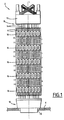
- the fuel assembly 2 of Figure 1 is elongated and extends along a longitudinal direction L.
- the fuel assembly 2 is intended to be inserted inside a reactor core and to rest on a lower core plate 4 with the longitudinal direction L oriented vertically.
- orientation such as downward, upward..., refer to the longitudinal direction L extending vertically.
- the fuel assembly 2 comprises a bundle of fuel rods 6 elongated along the longitudinal direction L and a structure 8 for supporting the fuel rods 6.
- the structure 8 comprises a lower nozzle 10 and an upper nozzle 12 spaced longitudinally, guide tubes 14 extending longitudinally between the lower nozzle 10 and the upper nozzle 12 and spacer grids 16 distributed along the guide tubes 14 between the lower nozzle 10 and the upper nozzle 12.
- the upper nozzle 12 is adapted for lifting up the fuel assembly 2 using a clamp.
- the guide tubes 14 connect the lower nozzle 10 to the upper nozzle 12 and maintain the longitudinal spacing between them.
- the lower nozzle 10 and the upper nozzle 12 are connected only by the guide tubes 14.
- the guide tubes 14 are tubular for allowing insertion of cluster rods which do not contain fissile material (not shown) inside the guide tubes 14 through the upper nozzle 12.
- Each spacer grid 16 extends transversally and defines a lattice of cells for receiving the guide tubes 14 and the fuel rods 6.
- the fuel rods 6 extend through the cells and are supported by the spacer grids 16.
- the fuel assembly 2 rests via the lower nozzle 10 on the lower core plate 4 above a coolant fluid inlet opening 18 of the lower core plate 4.
- the lower nozzle 10 supports the fuel assembly 2 and allows coolant fluid to flow vertically upwardly through the lower nozzle 10.
- the lower nozzle 10 comprises an upper plate 20, a tubular base 22 extending downwardly along a longitudinal axis A from the periphery of the upper plate 20 and a tubular inlet 24 extending the base 22.
- the base 22 extends longitudinally between an upper end 26 and a lower end 28.
- the upper end 26 and the lower end 28 have square outlines centred on the longitudinal axis A and the length of the outer edges of the lower end 28 is inferior to that of the upper end 26.
- the upper plate 20 extends transversely at the upper end 26 of the base 22 and is adapted for connecting the guide tubes 14 (represented in dotted line on Figure 2 ) and has openings for allowing coolant fluid flow through the upper plate 20.
- the lower end 28 is intended to rest against the lower core plate 4 at the periphery of an opening 18.
- the base 22 is provided at the lower end 28 with a bearing surface 29 extending transversely to the longitudinal axis A.
- the bearing surface 29 is symmetric around the longitudinal axis A.
- the lower nozzle 10 has a lateral surface 30 extending between the outer periphery of the lower end 28 and the outer periphery of the upper end 26.
- the lateral surface 30 is axisymmetric around the longitudinal axis A.
- the lateral surface 30 comprises a longitudinal lower segment 32 immediately adjacent the lower end 28, and one longitudinal upper segment 34 extending upwardly from the upper extremity of the lower segment 32, up to the upper end 26.
- the lower segment 32 is of reversed pyramidal shape and comprises four inclined faces 36 converging downwardly along the longitudinal axis A.
- Each inclined face 36 is inclined relative to the longitudinal axis A at an angle ⁇ comprised between 0.5 ° and 15°.
- the pyramid shaped lower segment 32 is conical and the inclination of each inclined face 36 relative to the longitudinal axis A equals the half-cone angle of the lower segment 32.
- the lower segment 32 has transverse dimensions decreasing progressively and continuously downwardly along the longitudinal axis A.
- the lower segment 32 tapers downwardly progressively and continuously in side view in any direction perpendicular to the longitudinal axis A, symmetrically relative to the longitudinal axis A.
- the lower segment 32 extends on at least 50% the height H of the lateral surface 30 taken along the longitudinal axis A between the lower end 28 and the upper end 26, preferably at least 70%.
- the upper segment 34 is cylindrical around the longitudinal axis A. It has a constant square transverse cross-section corresponding to the outline of the upper end 26.
- the upper segment 34 comprises four flat longitudinal faces 38 parallel to the longitudinal axis A.
- the inlet 24 extends downwardly along the longitudinal axis A from the lower end 28 of the base 22.
- the inlet 24 is conical of circular transverse cross-section and downwardly converging.
- the fuel assembly 2 might bend along the longitudinal direction L due to severe operating conditions and its structure 8 in which the lower nozzle 10 and the upper nozzle 12 are connected by the guide tubes 14 only.
- the fuel assembly 2 is lifted down with controlling the position of the upper nozzle 12.
- the lower nozzle 10 may offset laterally and/or be inclined relative to the vertical direction due to the bending and might abut by its lower end 28 or grate by its lateral surface 30 against the lower nozzle of the adjacent fuel assembly 40.
- the lower end 28 having an outline of smaller transverse dimensions than that of the upper end 26 limits the risk that the lower end 28 will abut the lower nozzle of the adjacent fuel assembly 40.
- the tapered lower segment 32 limits the risk of grating with the lower nozzle of the adjacent fuel assembly 40. Any contact will be delayed in the stroke of the downward movement of the fuel assembly 2 and progressive thus limiting the risk of damages. Any gratings will occur on a reduced longitudinal stroke.
- the continuous and progressive tapering of the lower segment 32 ensures that the lower segment 32 is smooth and has no protruding abutment portion.
- the extension of the tapered lower segment 32 on a significant portion of the height H of the lower nozzle 10 allows maintaining sufficient transverse dimensions for the bearing surface 29 of the lower end 28 which has to support the weight of the fuel assembly 2 while allowing significant reduction of abutment risks and grating risks.
- the height H of the lower nozzle 10 taken between the lower end 28 and the upper end 26 is of approximately 105 mm, and the height of the tapered lower segment 32 is of 100 mm.
- the conical inlet 24 provide similar advantages with respect to the edge of the opening 18 of the lower core plate 4 into which the inlet 24 is inserted during positioning of the fuel assembly 2 into the reactor core.
- the upper segment 34 having faces 38 parallel to the longitudinal axis A allows creating a narrow passage having an important flow resistance between the adjacent lower nozzles which can limit the flow of coolant fluid flowing between the adjacent lower nozzles and bypassing the fuel assemblies.
- the proportion of the lower segment relative to the upper segment is chosen to lower abutment and grating risks or consequences while limiting coolant fluid flows bypassing the fuel assemblies.
- the lower nozzle 42 of Figure 5 differs from that of Figure 1 - 4 by the feature that the base 22 comprises a tubular skirt 44 extending downwardly from the periphery of the upper plate 20 and four corner feet 46 each extending downwardly from a respective corner of the skirt 44 (only two feet 46 are visible on Figure 5 ).
- Each pair of feet 46 defines with the lower edge 47 of the skirt 44 a lateral opening.
- Each foot 46 is provided at its lower end 48 with a lower bearing face for resting onto a lower core plate 4.
- the lower ends 48 of the feet 46 define the lower end 28 of the base 22.
- the lower end 28 has a square outline 50 (represented in dash-doted lines on Figure 6 ).
- the lateral surface 30 of the lower nozzle 42 extends on the feet 46 and on the skirt 44.
- the lateral surface 30 exhibits an overall reverse pyramidal shape and comprises a downwardly tapering lower segment 32 of downwardly decreasing square cross-section having four faces 36 and a cylindrical upper segment 34 of constant square cross-section.
- the lower segment 32 extends longitudinally from the lower end 28 up to a level above the lower edge 47 of the skirt 44 and the upper segment 34 extends in the remaining portion of the skirt 44. In an alternative, the lower segment 32 extends to a level below the skirt 44.
- the upper face and the lower face of the lower nozzle are not limited to square outlines as illustrated in the embodiments of Figures 1 - 4 and 5 .
- the lower nozzle has an upper face and an lower face of hexagonal outlines and the tapered segment of the lateral surface has a reversed pyramidal shape of hexagonal base with faces inclined relative to the longitudinal axis A.
- the lower nozzle has transverse cross-section of polygonal outline and the tapered segment of the lateral face of the lower nozzle is of reversed pyramidal shape with its faces inclined relative to the longitudinal axis A.
- the tapered segment is not limited to conical surfaces such as pyramid shaped surfaces and may be more generally a ruled surface.
- the lower nozzle has an upper surface of polygonal outline (e.g. hexagonal outline), a lower surface of circular outline and the tapered segment is a ruled surface defined by rectilinear lines passing by a polygonal outline and a circular outline, the rectilinear lines being inclined inwardly and downwardly relative to the longitudinal axis A.
- polygonal outline e.g. hexagonal outline
- the tapered segment is a ruled surface defined by rectilinear lines passing by a polygonal outline and a circular outline, the rectilinear lines being inclined inwardly and downwardly relative to the longitudinal axis A.
- the tapered segment is not limited to ruled surface and may exhibit concavity or convexity in the longitudinal direction.
- the tapered segment tapers downwardly continuously and progressively in side view in any transverse direction perpendicular to the longitudinal axis A, preferably symmetrically relative to the longitudinal axis A of the lower nozzle.
Landscapes
- Physics & Mathematics (AREA)
- Engineering & Computer Science (AREA)
- Plasma & Fusion (AREA)
- General Engineering & Computer Science (AREA)
- High Energy & Nuclear Physics (AREA)
- Monitoring And Testing Of Nuclear Reactors (AREA)
- Nozzles (AREA)
Claims (11)
- Untere Düse (10, 42) für Brennelemente zum Einsatz in einem Druckwasserreaktor (PWR) des Typs, der ein oberes Ende (26) und ein unteres Ende (28) für die untere Düse (10, 42), das auf einer unteren Kernplatte (4) eines Reaktorkerns aufsitzt, sowie eine seitliche Fläche (30) umfasst, die entlang einer Längsachse (A) von dem unteren Ende (28) zu dem oberen Ende (26) verläuft,
dadurch gekennzeichnet, dass die seitliche Fläche (30) ein Längssegment (32) umfasst, das sich entlang der Längsachse (A) nach unten zunehmend und kontinuierlich verjüngt und sich an wenigstens 50% der Höhe (H) der seitlichen Fläche (30) entlang erstreckt. - Untere Düse für Brennelemente nach Anspruch 1, wobei sich das sich verjüngende Längssegment (32) in Seitenansicht in jeder beliebigen Querrichtung senkrecht zu der Längsachse (A) kontinuierlich und zunehmend nach unten verjüngt.
- Untere Düse für Brennelemente nach Anspruch 1 oder 2, wobei sich das sich verjüngende Längssegment (32) symmetrisch relativ zu der Längsachse (A) verjüngt.
- Untere Düse für Brennelemente nach einem der vorangehenden Ansprüche, wobei das sich verjüngende Längssegment (32) geradlinig ist.
- Untere Düse für Brennelemente nach einem der vorangehenden Ansprüche, wobei das sich verjüngende Längssegment (32) konisch ist.
- Untere Düse für Brennelemente nach Anspruch 5, wobei das sich verjüngende Längssegment (32) vieleckigen Querschnitt, d.h. quadratischen oder sechseckigen Querschnitt, hat.
- Untere Düse für Brennelemente nach Anspruch 5 oder 6, wobei der Halbkegelwinkel des sich verjüngenden Längssegmentes (32) zwischen 0,5° und 15° liegt.
- Untere Düse für Brennelemente nach einem der vorangehenden Ansprüche, wobei sich das sich verjüngende Längssegment (32) an wenigstens 70% der Höhe (H) der seitlichen Fläche (30) entlang erstreckt.
- Untere Düse für Brennelemente nach einem der vorangehenden Ansprüche, wobei die seitliche Fläche (30) ein zylindrisches Segment (34) umfasst, das das sich verjüngende Längssegment (32) bis zum oberen Ende (26) nach oben verlängert.
- Untere Düse für Brennelemente nach einem der vorangehenden Ansprüche, das einen röhrenförmigen Wassereinlass (24) umfasst, der die untere Düse entlang der Längsachse (A) vom unteren Ende (28) nach unten verlängert, wobei der Wassereinlasse (24) eine Außenfläche hat, die sich zunehmend und kontinuierlich nach unten verjüngt.
- Brennelement (2) zum Einsatz in einem Druckwasserreaktor (PWR), das ein Bündel länglicher Brennstäbe (6) und eine Struktur (8) zum Tragen der Brennstäbe umfasst, wobei die Struktur eine untere Düse (10, 42) sowie eine obere Düse (12) umfasst, die in Längsrichtung beabstandet sind, Führungsröhren (14), die die Düsen (10, 12) verbinden, und Abstandshaltegitter (16) umfasst, die an den Führungsröhren (14) befestigt und über ihre Länge verteilt sind, wobei die Brennstäbe (6) von den Abstandshaltegittern (16) getragen werden und die untere Düse (10) eine untere Düse für Brennelemente nach einem der vorangehenden Ansprüche ist.
Priority Applications (7)
| Application Number | Priority Date | Filing Date | Title |
|---|---|---|---|
| ES08305799T ES2379126T3 (es) | 2008-11-12 | 2008-11-12 | Tobera inferior para conjunto de combustible nuclear para un reactor de agua presurizada |
| EP08305799A EP2187402B1 (de) | 2008-11-12 | 2008-11-12 | Untere Düse eines Brennstabbündels für einen Druckwasserreaktor |
| AT08305799T ATE541296T1 (de) | 2008-11-12 | 2008-11-12 | Untere düse eines brennstabbündels für einen druckwasserreaktor |
| US13/128,598 US20110280361A1 (en) | 2008-11-12 | 2009-11-09 | Lower nozzle for nuclear fuel assembly for pressurized water reactor |
| JP2011535987A JP2012508389A (ja) | 2008-11-12 | 2009-11-09 | 加圧水型原子炉のための核燃料集合体の下部ノズル |
| PCT/EP2009/064856 WO2010055015A1 (en) | 2008-11-12 | 2009-11-09 | Lower nozzle for nuclear fuel assembly for pressurized water reactor. |
| CN2009801530267A CN102272857A (zh) | 2008-11-12 | 2009-11-09 | 压水反应堆核燃料组件的下管口 |
Applications Claiming Priority (1)
| Application Number | Priority Date | Filing Date | Title |
|---|---|---|---|
| EP08305799A EP2187402B1 (de) | 2008-11-12 | 2008-11-12 | Untere Düse eines Brennstabbündels für einen Druckwasserreaktor |
Publications (2)
| Publication Number | Publication Date |
|---|---|
| EP2187402A1 EP2187402A1 (de) | 2010-05-19 |
| EP2187402B1 true EP2187402B1 (de) | 2012-01-11 |
Family
ID=40428179
Family Applications (1)
| Application Number | Title | Priority Date | Filing Date |
|---|---|---|---|
| EP08305799A Active EP2187402B1 (de) | 2008-11-12 | 2008-11-12 | Untere Düse eines Brennstabbündels für einen Druckwasserreaktor |
Country Status (7)
| Country | Link |
|---|---|
| US (1) | US20110280361A1 (de) |
| EP (1) | EP2187402B1 (de) |
| JP (1) | JP2012508389A (de) |
| CN (1) | CN102272857A (de) |
| AT (1) | ATE541296T1 (de) |
| ES (1) | ES2379126T3 (de) |
| WO (1) | WO2010055015A1 (de) |
Families Citing this family (3)
| Publication number | Priority date | Publication date | Assignee | Title |
|---|---|---|---|---|
| CN104488034A (zh) * | 2012-04-17 | 2015-04-01 | 巴布科克和威尔科克斯M能量股份有限公司 | 下端配件定位销 |
| US10665353B2 (en) * | 2013-05-22 | 2020-05-26 | Westinghouse Electric Company Llc | VVER-1000 fuel assembly bottom nozzle |
| JP2015017808A (ja) * | 2013-07-08 | 2015-01-29 | 株式会社東芝 | 燃料集合体の上部タイプレートの把持装置および把持方法 |
Family Cites Families (8)
| Publication number | Priority date | Publication date | Assignee | Title |
|---|---|---|---|---|
| GB1190409A (en) * | 1966-09-23 | 1970-05-06 | Gen Electric | Nuclear Reactor Fuel Bundle |
| JPS5985993A (ja) * | 1982-11-08 | 1984-05-18 | 三菱原子力工業株式会社 | 核燃料集合体の下部炉心板への装荷構造 |
| FR2585499B1 (fr) * | 1985-07-29 | 1989-10-27 | Fragema Framatome & Cogema | Dispositif de maintien hydraulique pour assemblage combustible nucleaire et reacteur nucleaire en comportant application |
| JPH02167496A (ja) * | 1988-12-21 | 1990-06-27 | Nippon Nuclear Fuel Dev Co Ltd | 核燃料集合体 |
| JPH06308266A (ja) * | 1993-04-22 | 1994-11-04 | Toshiba Corp | 原子炉の燃料構造および燃料交換方法 |
| SE503413C2 (sv) * | 1993-11-25 | 1996-06-10 | Asea Atom Ab | Bränslepatron för en kärnreaktor |
| FR2848328B1 (fr) * | 2002-12-10 | 2005-08-19 | Framatome Anp | Procede et dispositif de chargement d'un assemblage de combustible dans le coeur d'un reacteur nucleaire. |
| FR2910170B1 (fr) * | 2006-12-13 | 2009-04-03 | Areva Np Sas | Embout inferieur a dispositif anti-debris a chicane pour assemblage de combustible nucleaire et assemblage correspondant |
-
2008
- 2008-11-12 EP EP08305799A patent/EP2187402B1/de active Active
- 2008-11-12 AT AT08305799T patent/ATE541296T1/de active
- 2008-11-12 ES ES08305799T patent/ES2379126T3/es active Active
-
2009
- 2009-11-09 US US13/128,598 patent/US20110280361A1/en not_active Abandoned
- 2009-11-09 WO PCT/EP2009/064856 patent/WO2010055015A1/en not_active Ceased
- 2009-11-09 CN CN2009801530267A patent/CN102272857A/zh active Pending
- 2009-11-09 JP JP2011535987A patent/JP2012508389A/ja active Pending
Also Published As
| Publication number | Publication date |
|---|---|
| WO2010055015A1 (en) | 2010-05-20 |
| EP2187402A1 (de) | 2010-05-19 |
| CN102272857A (zh) | 2011-12-07 |
| JP2012508389A (ja) | 2012-04-05 |
| US20110280361A1 (en) | 2011-11-17 |
| ATE541296T1 (de) | 2012-01-15 |
| ES2379126T3 (es) | 2012-04-23 |
Similar Documents
| Publication | Publication Date | Title |
|---|---|---|
| US4795608A (en) | Nuclear fuel assembly | |
| US6807246B1 (en) | Lips-type multi-purposed nuclear fuel assembly spacer grid | |
| EP2187402B1 (de) | Untere Düse eines Brennstabbündels für einen Druckwasserreaktor | |
| KR101769179B1 (ko) | 최적화된 플라워 튜브 및 최적 향상된 그리드 구성 | |
| CN104838447A (zh) | 用于核燃料组件定位格架的燃料棒支撑插入件、定位格架和核燃料组件 | |
| JP2001514753A (ja) | 原子炉燃料集合体 | |
| EP0455011A1 (de) | Trümmerfestes Kernbrennstabbündelfussstück | |
| US7804930B2 (en) | Nuclear fuel assembly comprising a reinforcing mesh device and the use of one such device in a nuclear fuel assembly | |
| WO2013172889A1 (en) | Lower end fitting for nuclear fuel assembly made from intersecting metal strips | |
| CN101589438B (zh) | 具有马鞍形支承件的隔栅及相应的核燃料组件 | |
| US20110033020A1 (en) | Helically fluted tubular fuel rod support | |
| KR101163998B1 (ko) | 교차파형 상하딤플 지지형 이중냉각 핵연료봉 지지격자체 | |
| EP0289732A2 (de) | Wiederzusammenbaubares Kernbrennstoffbündel | |
| US20140064435A1 (en) | Nuclear fuel assembly for boiling water reactor comprising a fuel channel spacer | |
| KR101474548B1 (ko) | 유체유발 진동 저감을 위한 보호 지지격자를 갖는 핵연료 집합체 | |
| JP2014519030A (ja) | 核燃料アセンブリで使用するための下側ノズル | |
| CA2857076C (en) | Decanter | |
| JP6560861B2 (ja) | 燃料集合体 | |
| EP3001426A1 (de) | Brennelement für Siedewassereaktor | |
| CN106809505B (zh) | 一种中子温度测量通道的固定支架 | |
| US8675804B2 (en) | Boiling water reactor fuel support casting flow limiter | |
| EP4348685B1 (de) | Bodendüse und kernbrennstabbündel mit einer solchen bodendüse | |
| US8548113B2 (en) | Debris mitigation upper tie plates and fuel bundles using the same | |
| EP4016547A1 (de) | Abstandsgitterelement eines abstandsgitters für kernbrennstabbündel, abstandsgitter und kernbrennstabbündel | |
| JP6602661B2 (ja) | 沸騰水型原子炉の燃料交換用治具及び燃料交換方法 |
Legal Events
| Date | Code | Title | Description |
|---|---|---|---|
| PUAI | Public reference made under article 153(3) epc to a published international application that has entered the european phase |
Free format text: ORIGINAL CODE: 0009012 |
|
| AK | Designated contracting states |
Kind code of ref document: A1 Designated state(s): AT BE BG CH CY CZ DE DK EE ES FI FR GB GR HR HU IE IS IT LI LT LU LV MC MT NL NO PL PT RO SE SI SK TR |
|
| AX | Request for extension of the european patent |
Extension state: AL BA MK RS |
|
| 17P | Request for examination filed |
Effective date: 20100701 |
|
| 17Q | First examination report despatched |
Effective date: 20100820 |
|
| AKX | Designation fees paid |
Designated state(s): AT BE BG CH CY CZ DE DK EE ES FI FR GB GR HR HU IE IS IT LI LT LU LV MC MT NL NO PL PT RO SE SI SK TR |
|
| GRAP | Despatch of communication of intention to grant a patent |
Free format text: ORIGINAL CODE: EPIDOSNIGR1 |
|
| GRAS | Grant fee paid |
Free format text: ORIGINAL CODE: EPIDOSNIGR3 |
|
| GRAA | (expected) grant |
Free format text: ORIGINAL CODE: 0009210 |
|
| AK | Designated contracting states |
Kind code of ref document: B1 Designated state(s): AT BE BG CH CY CZ DE DK EE ES FI FR GB GR HR HU IE IS IT LI LT LU LV MC MT NL NO PL PT RO SE SI SK TR |
|
| REG | Reference to a national code |
Ref country code: GB Ref legal event code: FG4D |
|
| REG | Reference to a national code |
Ref country code: CH Ref legal event code: EP |
|
| REG | Reference to a national code |
Ref country code: AT Ref legal event code: REF Ref document number: 541296 Country of ref document: AT Kind code of ref document: T Effective date: 20120115 |
|
| REG | Reference to a national code |
Ref country code: IE Ref legal event code: FG4D |
|
| REG | Reference to a national code |
Ref country code: DE Ref legal event code: R096 Ref document number: 602008012637 Country of ref document: DE Effective date: 20120315 |
|
| REG | Reference to a national code |
Ref country code: ES Ref legal event code: FG2A Ref document number: 2379126 Country of ref document: ES Kind code of ref document: T3 Effective date: 20120423 |
|
| REG | Reference to a national code |
Ref country code: NL Ref legal event code: VDEP Effective date: 20120111 |
|
| PG25 | Lapsed in a contracting state [announced via postgrant information from national office to epo] |
Ref country code: SI Free format text: LAPSE BECAUSE OF FAILURE TO SUBMIT A TRANSLATION OF THE DESCRIPTION OR TO PAY THE FEE WITHIN THE PRESCRIBED TIME-LIMIT Effective date: 20120111 |
|
| LTIE | Lt: invalidation of european patent or patent extension |
Effective date: 20120111 |
|
| PG25 | Lapsed in a contracting state [announced via postgrant information from national office to epo] |
Ref country code: BE Free format text: LAPSE BECAUSE OF FAILURE TO SUBMIT A TRANSLATION OF THE DESCRIPTION OR TO PAY THE FEE WITHIN THE PRESCRIBED TIME-LIMIT Effective date: 20120111 Ref country code: HR Free format text: LAPSE BECAUSE OF FAILURE TO SUBMIT A TRANSLATION OF THE DESCRIPTION OR TO PAY THE FEE WITHIN THE PRESCRIBED TIME-LIMIT Effective date: 20120111 Ref country code: IS Free format text: LAPSE BECAUSE OF FAILURE TO SUBMIT A TRANSLATION OF THE DESCRIPTION OR TO PAY THE FEE WITHIN THE PRESCRIBED TIME-LIMIT Effective date: 20120511 Ref country code: LT Free format text: LAPSE BECAUSE OF FAILURE TO SUBMIT A TRANSLATION OF THE DESCRIPTION OR TO PAY THE FEE WITHIN THE PRESCRIBED TIME-LIMIT Effective date: 20120111 Ref country code: NO Free format text: LAPSE BECAUSE OF FAILURE TO SUBMIT A TRANSLATION OF THE DESCRIPTION OR TO PAY THE FEE WITHIN THE PRESCRIBED TIME-LIMIT Effective date: 20120411 Ref country code: BG Free format text: LAPSE BECAUSE OF FAILURE TO SUBMIT A TRANSLATION OF THE DESCRIPTION OR TO PAY THE FEE WITHIN THE PRESCRIBED TIME-LIMIT Effective date: 20120411 Ref country code: NL Free format text: LAPSE BECAUSE OF FAILURE TO SUBMIT A TRANSLATION OF THE DESCRIPTION OR TO PAY THE FEE WITHIN THE PRESCRIBED TIME-LIMIT Effective date: 20120111 |
|
| PG25 | Lapsed in a contracting state [announced via postgrant information from national office to epo] |
Ref country code: GR Free format text: LAPSE BECAUSE OF FAILURE TO SUBMIT A TRANSLATION OF THE DESCRIPTION OR TO PAY THE FEE WITHIN THE PRESCRIBED TIME-LIMIT Effective date: 20120412 Ref country code: LV Free format text: LAPSE BECAUSE OF FAILURE TO SUBMIT A TRANSLATION OF THE DESCRIPTION OR TO PAY THE FEE WITHIN THE PRESCRIBED TIME-LIMIT Effective date: 20120111 Ref country code: PL Free format text: LAPSE BECAUSE OF FAILURE TO SUBMIT A TRANSLATION OF THE DESCRIPTION OR TO PAY THE FEE WITHIN THE PRESCRIBED TIME-LIMIT Effective date: 20120111 Ref country code: FI Free format text: LAPSE BECAUSE OF FAILURE TO SUBMIT A TRANSLATION OF THE DESCRIPTION OR TO PAY THE FEE WITHIN THE PRESCRIBED TIME-LIMIT Effective date: 20120111 Ref country code: PT Free format text: LAPSE BECAUSE OF FAILURE TO SUBMIT A TRANSLATION OF THE DESCRIPTION OR TO PAY THE FEE WITHIN THE PRESCRIBED TIME-LIMIT Effective date: 20120511 |
|
| REG | Reference to a national code |
Ref country code: AT Ref legal event code: MK05 Ref document number: 541296 Country of ref document: AT Kind code of ref document: T Effective date: 20120111 |
|
| PG25 | Lapsed in a contracting state [announced via postgrant information from national office to epo] |
Ref country code: CY Free format text: LAPSE BECAUSE OF FAILURE TO SUBMIT A TRANSLATION OF THE DESCRIPTION OR TO PAY THE FEE WITHIN THE PRESCRIBED TIME-LIMIT Effective date: 20120111 |
|
| PG25 | Lapsed in a contracting state [announced via postgrant information from national office to epo] |
Ref country code: DK Free format text: LAPSE BECAUSE OF FAILURE TO SUBMIT A TRANSLATION OF THE DESCRIPTION OR TO PAY THE FEE WITHIN THE PRESCRIBED TIME-LIMIT Effective date: 20120111 Ref country code: RO Free format text: LAPSE BECAUSE OF FAILURE TO SUBMIT A TRANSLATION OF THE DESCRIPTION OR TO PAY THE FEE WITHIN THE PRESCRIBED TIME-LIMIT Effective date: 20120111 Ref country code: SE Free format text: LAPSE BECAUSE OF FAILURE TO SUBMIT A TRANSLATION OF THE DESCRIPTION OR TO PAY THE FEE WITHIN THE PRESCRIBED TIME-LIMIT Effective date: 20120111 Ref country code: CZ Free format text: LAPSE BECAUSE OF FAILURE TO SUBMIT A TRANSLATION OF THE DESCRIPTION OR TO PAY THE FEE WITHIN THE PRESCRIBED TIME-LIMIT Effective date: 20120111 Ref country code: EE Free format text: LAPSE BECAUSE OF FAILURE TO SUBMIT A TRANSLATION OF THE DESCRIPTION OR TO PAY THE FEE WITHIN THE PRESCRIBED TIME-LIMIT Effective date: 20120111 |
|
| PLBE | No opposition filed within time limit |
Free format text: ORIGINAL CODE: 0009261 |
|
| STAA | Information on the status of an ep patent application or granted ep patent |
Free format text: STATUS: NO OPPOSITION FILED WITHIN TIME LIMIT |
|
| PG25 | Lapsed in a contracting state [announced via postgrant information from national office to epo] |
Ref country code: IT Free format text: LAPSE BECAUSE OF FAILURE TO SUBMIT A TRANSLATION OF THE DESCRIPTION OR TO PAY THE FEE WITHIN THE PRESCRIBED TIME-LIMIT Effective date: 20120111 Ref country code: SK Free format text: LAPSE BECAUSE OF FAILURE TO SUBMIT A TRANSLATION OF THE DESCRIPTION OR TO PAY THE FEE WITHIN THE PRESCRIBED TIME-LIMIT Effective date: 20120111 |
|
| 26N | No opposition filed |
Effective date: 20121012 |
|
| PG25 | Lapsed in a contracting state [announced via postgrant information from national office to epo] |
Ref country code: AT Free format text: LAPSE BECAUSE OF FAILURE TO SUBMIT A TRANSLATION OF THE DESCRIPTION OR TO PAY THE FEE WITHIN THE PRESCRIBED TIME-LIMIT Effective date: 20120111 |
|
| REG | Reference to a national code |
Ref country code: DE Ref legal event code: R097 Ref document number: 602008012637 Country of ref document: DE Effective date: 20121012 |
|
| REG | Reference to a national code |
Ref country code: CH Ref legal event code: PL |
|
| GBPC | Gb: european patent ceased through non-payment of renewal fee |
Effective date: 20121112 |
|
| PG25 | Lapsed in a contracting state [announced via postgrant information from national office to epo] |
Ref country code: CH Free format text: LAPSE BECAUSE OF NON-PAYMENT OF DUE FEES Effective date: 20121130 Ref country code: LI Free format text: LAPSE BECAUSE OF NON-PAYMENT OF DUE FEES Effective date: 20121130 |
|
| REG | Reference to a national code |
Ref country code: IE Ref legal event code: MM4A |
|
| REG | Reference to a national code |
Ref country code: FR Ref legal event code: ST Effective date: 20130731 |
|
| PG25 | Lapsed in a contracting state [announced via postgrant information from national office to epo] |
Ref country code: IE Free format text: LAPSE BECAUSE OF NON-PAYMENT OF DUE FEES Effective date: 20121112 |
|
| PG25 | Lapsed in a contracting state [announced via postgrant information from national office to epo] |
Ref country code: MT Free format text: LAPSE BECAUSE OF FAILURE TO SUBMIT A TRANSLATION OF THE DESCRIPTION OR TO PAY THE FEE WITHIN THE PRESCRIBED TIME-LIMIT Effective date: 20120111 Ref country code: FR Free format text: LAPSE BECAUSE OF NON-PAYMENT OF DUE FEES Effective date: 20121130 Ref country code: GB Free format text: LAPSE BECAUSE OF NON-PAYMENT OF DUE FEES Effective date: 20121112 |
|
| PG25 | Lapsed in a contracting state [announced via postgrant information from national office to epo] |
Ref country code: TR Free format text: LAPSE BECAUSE OF FAILURE TO SUBMIT A TRANSLATION OF THE DESCRIPTION OR TO PAY THE FEE WITHIN THE PRESCRIBED TIME-LIMIT Effective date: 20120111 Ref country code: MC Free format text: LAPSE BECAUSE OF NON-PAYMENT OF DUE FEES Effective date: 20121130 |
|
| PG25 | Lapsed in a contracting state [announced via postgrant information from national office to epo] |
Ref country code: LU Free format text: LAPSE BECAUSE OF NON-PAYMENT OF DUE FEES Effective date: 20121112 |
|
| PG25 | Lapsed in a contracting state [announced via postgrant information from national office to epo] |
Ref country code: HU Free format text: LAPSE BECAUSE OF FAILURE TO SUBMIT A TRANSLATION OF THE DESCRIPTION OR TO PAY THE FEE WITHIN THE PRESCRIBED TIME-LIMIT Effective date: 20081112 |
|
| REG | Reference to a national code |
Ref country code: DE Ref legal event code: R082 Ref document number: 602008012637 Country of ref document: DE Representative=s name: LAVOIX MUNICH, DE |
|
| PGFP | Annual fee paid to national office [announced via postgrant information from national office to epo] |
Ref country code: DE Payment date: 20191115 Year of fee payment: 12 |
|
| REG | Reference to a national code |
Ref country code: DE Ref legal event code: R119 Ref document number: 602008012637 Country of ref document: DE |
|
| PG25 | Lapsed in a contracting state [announced via postgrant information from national office to epo] |
Ref country code: DE Free format text: LAPSE BECAUSE OF NON-PAYMENT OF DUE FEES Effective date: 20210601 |
|
| PGFP | Annual fee paid to national office [announced via postgrant information from national office to epo] |
Ref country code: ES Payment date: 20231218 Year of fee payment: 16 |