EP2186710A1 - Hydrostatische Lenkvorrichtung - Google Patents
Hydrostatische Lenkvorrichtung Download PDFInfo
- Publication number
- EP2186710A1 EP2186710A1 EP09175629A EP09175629A EP2186710A1 EP 2186710 A1 EP2186710 A1 EP 2186710A1 EP 09175629 A EP09175629 A EP 09175629A EP 09175629 A EP09175629 A EP 09175629A EP 2186710 A1 EP2186710 A1 EP 2186710A1
- Authority
- EP
- European Patent Office
- Prior art keywords
- steering
- doser
- devices
- jacket
- distribution device
- Prior art date
- Legal status (The legal status is an assumption and is not a legal conclusion. Google has not performed a legal analysis and makes no representation as to the accuracy of the status listed.)
- Granted
Links
- 230000002706 hydrostatic effect Effects 0.000 title description 11
- 239000012530 fluid Substances 0.000 claims abstract description 16
- 238000007789 sealing Methods 0.000 claims 1
- 238000010586 diagram Methods 0.000 description 6
- 230000007935 neutral effect Effects 0.000 description 4
- 230000003213 activating effect Effects 0.000 description 2
- 230000004913 activation Effects 0.000 description 2
- 239000007788 liquid Substances 0.000 description 2
- 230000000703 anti-shock Effects 0.000 description 1
- 230000005540 biological transmission Effects 0.000 description 1
- 230000015572 biosynthetic process Effects 0.000 description 1
- 230000008859 change Effects 0.000 description 1
- 238000010276 construction Methods 0.000 description 1
- 230000008878 coupling Effects 0.000 description 1
- 238000010168 coupling process Methods 0.000 description 1
- 238000005859 coupling reaction Methods 0.000 description 1
- 230000001419 dependent effect Effects 0.000 description 1
- 230000000694 effects Effects 0.000 description 1
- 238000002635 electroconvulsive therapy Methods 0.000 description 1
- 230000007246 mechanism Effects 0.000 description 1
- 230000004048 modification Effects 0.000 description 1
- 238000012986 modification Methods 0.000 description 1
- 210000000056 organ Anatomy 0.000 description 1
Images


Classifications
-
- B—PERFORMING OPERATIONS; TRANSPORTING
- B62—LAND VEHICLES FOR TRAVELLING OTHERWISE THAN ON RAILS
- B62D—MOTOR VEHICLES; TRAILERS
- B62D5/00—Power-assisted or power-driven steering
- B62D5/06—Power-assisted or power-driven steering fluid, i.e. using a pressurised fluid for most or all the force required for steering a vehicle
- B62D5/09—Power-assisted or power-driven steering fluid, i.e. using a pressurised fluid for most or all the force required for steering a vehicle characterised by means for actuating valves
- B62D5/093—Telemotor driven by steering wheel movement
- B62D5/097—Telemotor driven by steering wheel movement gerotor type
-
- B—PERFORMING OPERATIONS; TRANSPORTING
- B62—LAND VEHICLES FOR TRAVELLING OTHERWISE THAN ON RAILS
- B62D—MOTOR VEHICLES; TRAILERS
- B62D5/00—Power-assisted or power-driven steering
- B62D5/06—Power-assisted or power-driven steering fluid, i.e. using a pressurised fluid for most or all the force required for steering a vehicle
- B62D5/30—Safety devices, e.g. alternate emergency power supply or transmission means to ensure steering upon failure of the primary steering means
- B62D5/32—Safety devices, e.g. alternate emergency power supply or transmission means to ensure steering upon failure of the primary steering means for telemotor systems
-
- F—MECHANICAL ENGINEERING; LIGHTING; HEATING; WEAPONS; BLASTING
- F15—FLUID-PRESSURE ACTUATORS; HYDRAULICS OR PNEUMATICS IN GENERAL
- F15B—SYSTEMS ACTING BY MEANS OF FLUIDS IN GENERAL; FLUID-PRESSURE ACTUATORS, e.g. SERVOMOTORS; DETAILS OF FLUID-PRESSURE SYSTEMS, NOT OTHERWISE PROVIDED FOR
- F15B2211/00—Circuits for servomotor systems
- F15B2211/20—Fluid pressure source, e.g. accumulator or variable axial piston pump
- F15B2211/205—Systems with pumps
- F15B2211/2053—Type of pump
- F15B2211/20561—Type of pump reversible
-
- F—MECHANICAL ENGINEERING; LIGHTING; HEATING; WEAPONS; BLASTING
- F15—FLUID-PRESSURE ACTUATORS; HYDRAULICS OR PNEUMATICS IN GENERAL
- F15B—SYSTEMS ACTING BY MEANS OF FLUIDS IN GENERAL; FLUID-PRESSURE ACTUATORS, e.g. SERVOMOTORS; DETAILS OF FLUID-PRESSURE SYSTEMS, NOT OTHERWISE PROVIDED FOR
- F15B2211/00—Circuits for servomotor systems
- F15B2211/20—Fluid pressure source, e.g. accumulator or variable axial piston pump
- F15B2211/205—Systems with pumps
- F15B2211/20576—Systems with pumps with multiple pumps
-
- F—MECHANICAL ENGINEERING; LIGHTING; HEATING; WEAPONS; BLASTING
- F15—FLUID-PRESSURE ACTUATORS; HYDRAULICS OR PNEUMATICS IN GENERAL
- F15B—SYSTEMS ACTING BY MEANS OF FLUIDS IN GENERAL; FLUID-PRESSURE ACTUATORS, e.g. SERVOMOTORS; DETAILS OF FLUID-PRESSURE SYSTEMS, NOT OTHERWISE PROVIDED FOR
- F15B2211/00—Circuits for servomotor systems
- F15B2211/70—Output members, e.g. hydraulic motors or cylinders or control therefor
- F15B2211/705—Output members, e.g. hydraulic motors or cylinders or control therefor characterised by the type of output members or actuators
- F15B2211/7051—Linear output members
- F15B2211/7053—Double-acting output members
- F15B2211/7054—Having equal piston areas
-
- F—MECHANICAL ENGINEERING; LIGHTING; HEATING; WEAPONS; BLASTING
- F15—FLUID-PRESSURE ACTUATORS; HYDRAULICS OR PNEUMATICS IN GENERAL
- F15B—SYSTEMS ACTING BY MEANS OF FLUIDS IN GENERAL; FLUID-PRESSURE ACTUATORS, e.g. SERVOMOTORS; DETAILS OF FLUID-PRESSURE SYSTEMS, NOT OTHERWISE PROVIDED FOR
- F15B2211/00—Circuits for servomotor systems
- F15B2211/70—Output members, e.g. hydraulic motors or cylinders or control therefor
- F15B2211/71—Multiple output members, e.g. multiple hydraulic motors or cylinders
- F15B2211/7107—Multiple output members, e.g. multiple hydraulic motors or cylinders the output members being mechanically linked
-
- F—MECHANICAL ENGINEERING; LIGHTING; HEATING; WEAPONS; BLASTING
- F15—FLUID-PRESSURE ACTUATORS; HYDRAULICS OR PNEUMATICS IN GENERAL
- F15B—SYSTEMS ACTING BY MEANS OF FLUIDS IN GENERAL; FLUID-PRESSURE ACTUATORS, e.g. SERVOMOTORS; DETAILS OF FLUID-PRESSURE SYSTEMS, NOT OTHERWISE PROVIDED FOR
- F15B2211/00—Circuits for servomotor systems
- F15B2211/80—Other types of control related to particular problems or conditions
- F15B2211/875—Control measures for coping with failures
- F15B2211/8757—Control measures for coping with failures using redundant components or assemblies
Definitions
- the invention relates to a hydrostatic steering system of a type comprising two steering units, each of which has its own oil pump, distributor organ and doser.
- hydrostatic steering systems are used on vehicles or boats in order to facilitate steering operations when, while requiring high activating forces, comfort and safety are at a premium for the driver.
- Typical examples of this are tractors, agricultural machines, lift trucks, earth-moving machines, boats.
- the unit comprises a hydraulic actuator which functions in two opposite directions, generally constituted by piston-cylinder group with through-stem, which is connected to the four-bar linkage of the steering.
- the hydraulic actuator is supplied via a slide valve distributor which directs controlled quantities of hydraulic fluid to the actuator to which it is connected, which hydraulic fluid is pressurised and supplied by the respective pump, and directs the fluid coming from the actuator to the discharge.
- the distributor can substantially take on three operating positions, in one of which, known as the neutral position, the pressurised fluid coming from the associated pump is sent directly to the discharge and thus the steering is not involved, while in both of the other two positions the pressurised fluid is sent to the hydraulic actuator which commands the steering in one direction or in the opposite direction, and the fluid coming from the hydraulic actuator is sent to the discharge.
- the distributor devices are generally of the slide and jacket valve type and comprise two cylindrical bodies, sealedly coupled, which take on various relative angular positions.
- the internal body commonly known as a slide
- the external body commonly known as a jacket
- the slide is axially hollow and is coupled to the steering wheel of the vehicle.
- the external body commonly known as a jacket, is torsionally connected to the slide by elastic means, limitedly to first small rotations, and by rigid means for rotations going beyond the definition of small.
- Both the slide and the jacket are provided with holes and axial channels distributed over their surfaces, which are well known to technical experts in the sector and which are located in reciprocal correspondence according to the relative angular position between the slide and the jacket.
- the elastic means maintain the jacket and the slide in the relative position corresponding to the neutral position, while the activation of the steering wheel changes the relative reciprocal position of slide and jacket in order to direct the hydraulic fluid in one or the other direction corresponding to the two different steering directions.
- connection between the steering wheel shaft and the slide is rigid, while the connection between the slide and the jacket is elastic and consequently the activating of the steering wheel causes a staggering between slide and jacket which is maintained constant as long as the steering wheel is actually being turned, while when the rotation of the steering wheel stops the elastic means return the jacket and slide into original phase.
- the quantity of fluid sent to the actuator is controlled by an orbital dosing device, known as a gerotor, the rotor of which is connected to the jacket of the distributor.
- the rotations of the gerotor device correspond to the rotations of the jacket, which is elastically connected to the steering wheel.
- the gerotor has the function of enabling passage of a dosed quantity of liquid for each rotation of the rotor.
- a gerotor unit is formed by an external stator having N lobes and an internal rotor having N-1 lobes, and which is obviously eccentric with respect to the outer body.
- little chambers are created between the external body, or stator, and the internal rotor, a volume of which little chambers varies in order to aspirate and expel the liquid.
- the fluid continues to be supplied by the distributor device to the hydraulic actuator which activates the steering in quantities controlled by the gerotor, and the wheels continue to change direction.
- each of the steering units is destined to act on the respective hydraulic actuator in order to activate the steering.
- the shaft of the steering activates, via a gear transmission system, two branch shafts, each of which is coupled to a distributor device and the relative gerotor.
- This arrangement makes the system subject to problems of synchrony between the two steering units, due to the inevitable play present in the mechanical coupling between the steering shaft and the two branch shafts.
- Document US 6 386 312 illustrates a steering system which also includes two steering units connected up in parallel, each comprising a pump and a distributor of the jacket type and a gerotor, in which the two distributors share the same jacket and the same slide, connected in rotation to the steering shaft, on which both rotors of the respective gerotors are keyed by means of a complicated intermediate mechanism.
- jacket distributors have to be adjacent to and in contact with respective gerotors.
- An aim of the present invention is to obviate the above-mentioned drawbacks, with a hydrostatic steering system comprising two steering units and which does not suffer from the problems typifying the prior art.
- a further aim of the present invention is that it realises a hydrostatic steering system which does not exhibit components whose length can give rise to hydraulic seal problems.
- a final aim of the invention is a system which exhibits a comparatively small number of mechanical connections among its components.
- the hydraulic steering system for vehicles of the invention is of a type comprising two steering units which are arranged in parallel to one another and comprising a pump, a distributor device of the jacket and slide type, associated to a respective gerotor dosing device, and a double-acting actuator device supplied by hydraulic fluid coming from the respective distributor device.
- the actuator devices of the two units are mechanically connected to one another and to the steering linkage of the vehicle, the slides of the distributor devices are solidly constrained in rotation and at least one of them is constrained in rotation to the steering shaft and the respective rotor by rigid means, and to the respective jacket by elastic means.
- the two distributor devices are identical and form, together with the gerotor doser devices, a single block in which the two doser devices are adjacent to one another and one of them is adjacent and hydraulically connected to the respective distributor device while the other is located at a distance from, and is hydraulically connected to, the respective distributor device.
- the four devices which make up the block are held together by a series of connecting screws which are equal in number to the cavities of the stator of the orbital distributors.
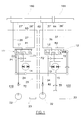
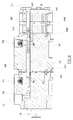
- Figure 1 shows a diagram of the hydraulic circuit of the hydrostatic steering system of the invention which exhibits a first 100 and a second 120 steering unit, which are arranged in parallel to one another.
- the steering units each exhibit a jacket distributor device respectively 11, 12 to which a gerotor, 13, 14, is associated.
- the rotors of each of the gerotors and the slides of each of the jacket distributors are connected in rotation to one another and to the steering wheels, via 15.
- the jacket distributor device 11 includes an inlet P1 connected by a line 24 to a first pump 22 and an outlet T1 connected by a line 25 to a first tank 23, while two outlets L1 and R1 are included, respectively connected by conduits 26 and 27 to the two chambers, right and left 27', 26', of a first double-acting actuator cylinder 160 which acts on the vehicle steering.
- the distributor device 12 includes an inlet P2 connected by a line 34 to a second pump 32 and an outlet T2 connected by a line 35 to a second tank 33, while two outlets L2 and R2 are included which are respectively connected via conduits 36 and 37 to the two chambers, right and left, 37' and 36', of a second double-acting actuator cylinder 161, also acting on the vehicle steering.
- the two double-acting cylinders each exhibit a piston 63, 64; the two pistons are located on the same through-stem 62.
- Each of the distributor devices 11, 12 is associated to a respective gerotor dosing device 13, 14.
- the hydraulic connection in the embodiment which will be described in greater detail herein below, is however realized such that the first distributor device 11 is connected hydraulically to the second gerotor 14, while the second distributor device 12 is connected hydraulically to the first gerotor 13 ( figure 3 ).
- Figure 1 shows the diagram of the hydraulic circuit when the system is in neutral position
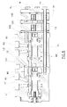
- figure 2 shows the diagram of the circuit of figure 1 when the system is in the steering position.
- the fluid pumped by each of the pumps, via the relative rotation of the jacket and the slide is sent to one of the two chambers of the respective double-acting cylinder, after being dosed by the gerotor device.
- Figure 2 in particular, represents a case in which the pressurised fluid is sent to the branch 27 of the first steering unit, and to the branch 37 of the second steering unit.
- the distribution units in the position represented, connect in discharge the branches 26 and 25 and respective 36 and 35, enabling the vehicle to be steered.
- the circuit also exhibits two one-way valves 72 and 82, of known type, for preventing return of hydraulic fluid towards the respective pumps 22, 32.
- Each hydraulic circuit can also comprise a normal and known anticavitation circuit inserted on the supply lines to the actuator of the steering; this enables oil to be aspirated from the tank of the respective circuit should the actuator cylinder be subjected to unexpected loads, thus preventing formation of a vacuum (cavitation) internally thereof.
- the anticavitation circuit is not illustrated as it is not involved with the invention.
- Each of the two hydraulic circuits illustrated also exhibits a usual maximum pressure valve, of known type: should the steering wheel be continued to be rotated when the steering actuator has reached its endrun position, the corresponding valve opens, placing the circuit in discharge mode.
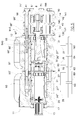
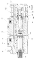
- the hydrostatic steering system includes, from the mechanical point of view, a block having a closing lid 8 in which a group of screws 71 is inserted, which screws 71 have the function of connecting up the two gerotors 13, 14 and the two distributor devices 11, 12 in the single block.
- the block 10, whose elements are mechanically connected up to one another, is coupled to the steering wheel of the vehicle via the connection 15 where the steering shaft is engaged.
- the jacket 20 is inside the distributor device 11, and the slide 21 is sealedly located internally of the jacket 20.
- the steering wheel is rigidly connected to the slide 21 by means of the connecting element 15, while the jacket 20 is torsionally connected to the slide by elastic means, in particular a group of leaf springs 17, which enable limited rotations.
- the slide 21 and the jacket 20 further exhibit a series of holes and grooves, of known type, which enable the two combinations of hydraulic connection to be made for steering to the right and to the left inasmuch as they are set in reciprocal correspondence according to the relative angular position between the slide 21 and the jacket 20.
- the distributor device 12 is similar to the one previously described and is located adjacently to the distributor unit 11.
- It comprises a jacket 30 and a slide 31, the slide being located internally of the jacket 30.
- the slide 31 is torsionally connected to the slide 21, while the jacket 30 is connected to the jacket 20.
- the two steering units are hydraulically independent, thanks also to the presence of a wall 92 which keeps the axial cavities of the two slides 21 and 31 separate.
- the combination of the elements 20, 21 and 30, 31 configures, for each distribution device, a distributor valve having a cylindrical slide which in the hydraulic diagram of figures 1 and 2 is respectively denoted by 11, 12.
- the two distribution devices 11, 12 are adjacent to one another, and thus the respective gerotor devices 13 and 14 are in reciprocal contact, only one of them being in contact with the respective distribution unit 12.
- the rotor of the gerotor 13 adjacent to the respective distribution unit 12 is connected to the jacket 30 of the distribution unit 12 via the known oscillating con rod 60, while the rotors of the two gerotor devices 13 and 14 are coaxial, in phase and mechanically connected in rotation by the mechanical connection element 188.
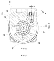
- Each gerotor is formed by a seven-lobe external stator 40, 50 and a six-lobe internal rotor 41, 51 which rolls internally of the stator.
- the indicated number of lobes is purely illustrative and not limiting, since realisations are possible which have a different number of lobes, as long as the internal rotor has N-1 lobes if the external stator has N lobes.
- the body of the gerotor 13 is connected to the adjacent distribution unit 12 by an interposed plate 130.
- the plate 130 exhibits seven holes 131 located at the gullies between the lobes of the rotator of the gerotor 13; the holes 131 are located at seven conduits 91, afforded in the body of the distributor device 12 and opening against the jacket 30 of the distribution device 12.
- the holes are set in communication with one or the other side of the actuator cylinder 161 of the steering through usual holes in the jacket and axial grooves in the slide.
- the gullies between the lobes of the stator of the gerotor device 13 are therefore in direct communication, via the plate 130, with the jacket of the distribution device 12.
- a plate 140 is located between the body of the doser device 14 and the body of the gerotor 13.
- the plate 140 exhibits seven blind holes 141 located at the gullies between the cogs of the external body of the gerotor.
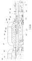
- Each of the blind holes 141, through a bean-shaped blind gully 142 ( figure 11 ) is in turn in communication with the space between the screws 71 and the respective containing hole.
- the stem of the screws 71 is, as mentioned, conformed such as to leave a space between the stem 71 and the containing hole; the oil directed to the distribution device 11 passes through this hole.
- Blind gullies 143 are afforded on the surface of the body of the distribution unit 12 which contactingly faces the surface of the body of the distribution device 11, which gullies 143 are similar to the gullies 142 (see figure 10 ) which set the containing seating of the screws 71 in communication with the end of a same number of conduits 90 (see figure 5 ) opening against the jacket 20 of the distribution device 11.
- the conduits 90 are closed or set in communication with one or the other side of the actuator cylinder 160 of the steering through a hole in the jacket and an axial groove.
- the screw 71' is made up of three parts, precisely: starting from the end thereof which involves the distributor device 11 it comprises a first part 93 destined to screw into the body of the distribution device 11, opening into the chamber 99 into which the conduit coming from the oil pump opens.
- the first part 93 is provided with an axial seating 93' destined to receive, by screwing, the threaded end of the second part 97 which substantially crosses the body of the distribution device 12, which is in turn provided with an axial cavity 97' destined to receive, by screwing, the threaded end of the third part 96 which crosses the body of both the gerotors 13 and 14, and terminates with the hexagonal head for engaging with the fastening key.
- the stem 97 of the screw 71' has a smaller diameter than the diameter of its own containing hole over almost all the length thereof, leaving the space 96' which connects the gerotor 14 to the distribution device 11 free.
- the space 96' is interrupted in the terminal portion of the second part 97 which is sealedly inserted in the hole with the help of the seals 940.
- the continuity of the hydraulic communication at the terminal portion of the second part 97 is guaranteed by the axial hole 98, which involves both the first part 96 and the second part 97 and opens, via the diameter holes 98', into the space, crossing the conduit opening towards the outside.
- This configuration enables the first distribution device 11 to isolatedly hydraulically supply the second gerotor 14.
Landscapes
- Engineering & Computer Science (AREA)
- Chemical & Material Sciences (AREA)
- Combustion & Propulsion (AREA)
- Transportation (AREA)
- Mechanical Engineering (AREA)
- Power Steering Mechanism (AREA)
- Guiding Agricultural Machines (AREA)
Applications Claiming Priority (1)
| Application Number | Priority Date | Filing Date | Title |
|---|---|---|---|
| ITRE2008A000106A IT1391837B1 (it) | 2008-11-11 | 2008-11-11 | Dispositivo di sterzatura idrostatica |
Publications (2)
| Publication Number | Publication Date |
|---|---|
| EP2186710A1 true EP2186710A1 (de) | 2010-05-19 |
| EP2186710B1 EP2186710B1 (de) | 2012-10-03 |
Family
ID=41020762
Family Applications (1)
| Application Number | Title | Priority Date | Filing Date |
|---|---|---|---|
| EP09175629A Active EP2186710B1 (de) | 2008-11-11 | 2009-11-11 | Hydrostatische Lenkvorrichtung |
Country Status (2)
| Country | Link |
|---|---|
| EP (1) | EP2186710B1 (de) |
| IT (1) | IT1391837B1 (de) |
Cited By (2)
| Publication number | Priority date | Publication date | Assignee | Title |
|---|---|---|---|---|
| EP3078570A1 (de) | 2015-04-08 | 2016-10-12 | Danfoss Power Solutions Aps | Hydraulisches lenksystem |
| EP2920105B1 (de) | 2012-11-15 | 2017-12-27 | Hubtex Maschinenbau GmbH & Co. KG | Lenksystem für ein flurförderzeug |
Citations (6)
| Publication number | Priority date | Publication date | Assignee | Title |
|---|---|---|---|---|
| US3509958A (en) * | 1966-10-18 | 1970-05-05 | Zahnradfabrik Friedrichshafen | Power steering apparatus,especially for motor vehicles |
| DD117652A1 (de) * | 1975-02-26 | 1976-01-20 | ||
| DE2944883A1 (de) * | 1979-11-07 | 1981-05-21 | Danfoss A/S, 6430 Nordborg | Hydrostatische lenkeinrichtung |
| WO1997047511A1 (en) * | 1996-06-07 | 1997-12-18 | Danfoss A/S | Hydrostatic steering device with two steering systems |
| DE19942544A1 (de) * | 1999-09-07 | 2001-03-22 | Mannesmann Rexroth Ag | Hydraulische Lenkeinrichtung mit Übersetzungsänderung |
| US6386312B1 (en) | 1999-09-21 | 2002-05-14 | Sauer-Danfoss Holding A/S | Hydrostatic steering arrangement with dual control systems |
-
2008
- 2008-11-11 IT ITRE2008A000106A patent/IT1391837B1/it active
-
2009
- 2009-11-11 EP EP09175629A patent/EP2186710B1/de active Active
Patent Citations (7)
| Publication number | Priority date | Publication date | Assignee | Title |
|---|---|---|---|---|
| US3509958A (en) * | 1966-10-18 | 1970-05-05 | Zahnradfabrik Friedrichshafen | Power steering apparatus,especially for motor vehicles |
| DD117652A1 (de) * | 1975-02-26 | 1976-01-20 | ||
| DE2944883A1 (de) * | 1979-11-07 | 1981-05-21 | Danfoss A/S, 6430 Nordborg | Hydrostatische lenkeinrichtung |
| DE2944883C2 (de) | 1979-11-07 | 1982-08-26 | Danfoss A/S, 6430 Nordborg | Hydrostatische Lenkeinrichtung |
| WO1997047511A1 (en) * | 1996-06-07 | 1997-12-18 | Danfoss A/S | Hydrostatic steering device with two steering systems |
| DE19942544A1 (de) * | 1999-09-07 | 2001-03-22 | Mannesmann Rexroth Ag | Hydraulische Lenkeinrichtung mit Übersetzungsänderung |
| US6386312B1 (en) | 1999-09-21 | 2002-05-14 | Sauer-Danfoss Holding A/S | Hydrostatic steering arrangement with dual control systems |
Cited By (4)
| Publication number | Priority date | Publication date | Assignee | Title |
|---|---|---|---|---|
| EP2920105B1 (de) | 2012-11-15 | 2017-12-27 | Hubtex Maschinenbau GmbH & Co. KG | Lenksystem für ein flurförderzeug |
| EP3078570A1 (de) | 2015-04-08 | 2016-10-12 | Danfoss Power Solutions Aps | Hydraulisches lenksystem |
| CN106043410A (zh) * | 2015-04-08 | 2016-10-26 | 丹佛斯动力系统有限公司 | 液压转向系统 |
| US9950737B2 (en) | 2015-04-08 | 2018-04-24 | Danfoss Power Solutions Aps | Hydraulic steering system |
Also Published As
| Publication number | Publication date |
|---|---|
| EP2186710B1 (de) | 2012-10-03 |
| IT1391837B1 (it) | 2012-01-27 |
| ITRE20080106A1 (it) | 2010-05-12 |
Similar Documents
| Publication | Publication Date | Title |
|---|---|---|
| US7766626B2 (en) | Multipiston pump | |
| EP2250068B1 (de) | Fluidsteuerung mit mehreren fluidmessern | |
| EP2186710B1 (de) | Hydrostatische Lenkvorrichtung | |
| EP2045168B1 (de) | Hydraulisches Lenksystem für ein Fahrzeug | |
| CA2996159C (en) | Pressure amplifier | |
| US6675576B2 (en) | Hydraulic circuit having a hydraulic motor equipped with a brake for a vehicle suitable for being towed | |
| US5065793A (en) | Fluid controller with load sensing priority flow control capability | |
| US4470432A (en) | Distributor for a hydraulic servo mechanism | |
| US11485410B2 (en) | Hydraulic steering device with variable ratio | |
| US6863147B2 (en) | Hydrostatic power steering device for fast steering | |
| GB2341159A (en) | Hydrostatic steering system with selectable reactive and non-reactive modes | |
| JP4329089B2 (ja) | 流体コントローラ | |
| US20120312625A1 (en) | Hydraulic Power Steering System | |
| US5970708A (en) | Hydraulic steering assembly with change in transmission ratio and flow amplification | |
| US11623684B2 (en) | Hydraulic steering unit | |
| DK2420430T3 (en) | Hydraulic control device | |
| BG64980B1 (bg) | Хидравлично кормилно управление с изменение на преводното отношение | |
| KR100471836B1 (ko) | 듀얼 서킷형 비상 동력 조향 장치 | |
| US11878748B2 (en) | Fluid controller, in particular as part of a hydraulic steering unit | |
| KR100489072B1 (ko) | 콘트롤밸브와 실린더가 일체형으로 된 유압식 조향장치 | |
| US20210284227A1 (en) | Fluid controller, in particular as part of a hydraulic steering unit | |
| USRE30291E (en) | Power steering system with auxiliary power capability | |
| WO2012021184A1 (en) | Power steering system | |
| EP0685650B1 (de) | Aussenzahnradhydraulikeinrichtung | |
| US20130220458A1 (en) | Distributor device for hydraulic power steering |
Legal Events
| Date | Code | Title | Description |
|---|---|---|---|
| PUAI | Public reference made under article 153(3) epc to a published international application that has entered the european phase |
Free format text: ORIGINAL CODE: 0009012 |
|
| AK | Designated contracting states |
Kind code of ref document: A1 Designated state(s): AT BE BG CH CY CZ DE DK EE ES FI FR GB GR HR HU IE IS IT LI LT LU LV MC MK MT NL NO PL PT RO SE SI SK SM TR |
|
| AX | Request for extension of the european patent |
Extension state: AL BA RS |
|
| 17P | Request for examination filed |
Effective date: 20101027 |
|
| RIC1 | Information provided on ipc code assigned before grant |
Ipc: F15B 18/00 20060101ALI20120110BHEP Ipc: B62D 5/32 20060101ALI20120110BHEP Ipc: B62D 5/097 20060101AFI20120110BHEP |
|
| GRAP | Despatch of communication of intention to grant a patent |
Free format text: ORIGINAL CODE: EPIDOSNIGR1 |
|
| GRAC | Information related to communication of intention to grant a patent modified |
Free format text: ORIGINAL CODE: EPIDOSCIGR1 |
|
| GRAS | Grant fee paid |
Free format text: ORIGINAL CODE: EPIDOSNIGR3 |
|
| GRAA | (expected) grant |
Free format text: ORIGINAL CODE: 0009210 |
|
| RAP1 | Party data changed (applicant data changed or rights of an application transferred) |
Owner name: OGNIBENE POWER S.P.A. |
|
| AK | Designated contracting states |
Kind code of ref document: B1 Designated state(s): AT BE BG CH CY CZ DE DK EE ES FI FR GB GR HR HU IE IS IT LI LT LU LV MC MK MT NL NO PL PT RO SE SI SK SM TR |
|
| REG | Reference to a national code |
Ref country code: GB Ref legal event code: FG4D |
|
| REG | Reference to a national code |
Ref country code: AT Ref legal event code: REF Ref document number: 577841 Country of ref document: AT Kind code of ref document: T Effective date: 20121015 Ref country code: CH Ref legal event code: EP |
|
| REG | Reference to a national code |
Ref country code: IE Ref legal event code: FG4D |
|
| REG | Reference to a national code |
Ref country code: DE Ref legal event code: R096 Ref document number: 602009010143 Country of ref document: DE Effective date: 20121129 |
|
| REG | Reference to a national code |
Ref country code: AT Ref legal event code: MK05 Ref document number: 577841 Country of ref document: AT Kind code of ref document: T Effective date: 20121003 |
|
| PG25 | Lapsed in a contracting state [announced via postgrant information from national office to epo] |
Ref country code: SI Free format text: LAPSE BECAUSE OF FAILURE TO SUBMIT A TRANSLATION OF THE DESCRIPTION OR TO PAY THE FEE WITHIN THE PRESCRIBED TIME-LIMIT Effective date: 20121003 |
|
| REG | Reference to a national code |
Ref country code: NL Ref legal event code: VDEP Effective date: 20121003 |
|
| REG | Reference to a national code |
Ref country code: LT Ref legal event code: MG4D |
|
| PG25 | Lapsed in a contracting state [announced via postgrant information from national office to epo] |
Ref country code: FI Free format text: LAPSE BECAUSE OF FAILURE TO SUBMIT A TRANSLATION OF THE DESCRIPTION OR TO PAY THE FEE WITHIN THE PRESCRIBED TIME-LIMIT Effective date: 20121003 Ref country code: NL Free format text: LAPSE BECAUSE OF FAILURE TO SUBMIT A TRANSLATION OF THE DESCRIPTION OR TO PAY THE FEE WITHIN THE PRESCRIBED TIME-LIMIT Effective date: 20121003 Ref country code: IS Free format text: LAPSE BECAUSE OF FAILURE TO SUBMIT A TRANSLATION OF THE DESCRIPTION OR TO PAY THE FEE WITHIN THE PRESCRIBED TIME-LIMIT Effective date: 20130203 Ref country code: NO Free format text: LAPSE BECAUSE OF FAILURE TO SUBMIT A TRANSLATION OF THE DESCRIPTION OR TO PAY THE FEE WITHIN THE PRESCRIBED TIME-LIMIT Effective date: 20130103 Ref country code: SE Free format text: LAPSE BECAUSE OF FAILURE TO SUBMIT A TRANSLATION OF THE DESCRIPTION OR TO PAY THE FEE WITHIN THE PRESCRIBED TIME-LIMIT Effective date: 20121003 Ref country code: ES Free format text: LAPSE BECAUSE OF FAILURE TO SUBMIT A TRANSLATION OF THE DESCRIPTION OR TO PAY THE FEE WITHIN THE PRESCRIBED TIME-LIMIT Effective date: 20130114 Ref country code: LT Free format text: LAPSE BECAUSE OF FAILURE TO SUBMIT A TRANSLATION OF THE DESCRIPTION OR TO PAY THE FEE WITHIN THE PRESCRIBED TIME-LIMIT Effective date: 20121003 Ref country code: HR Free format text: LAPSE BECAUSE OF FAILURE TO SUBMIT A TRANSLATION OF THE DESCRIPTION OR TO PAY THE FEE WITHIN THE PRESCRIBED TIME-LIMIT Effective date: 20121003 |
|
| PG25 | Lapsed in a contracting state [announced via postgrant information from national office to epo] |
Ref country code: PT Free format text: LAPSE BECAUSE OF FAILURE TO SUBMIT A TRANSLATION OF THE DESCRIPTION OR TO PAY THE FEE WITHIN THE PRESCRIBED TIME-LIMIT Effective date: 20130204 Ref country code: LV Free format text: LAPSE BECAUSE OF FAILURE TO SUBMIT A TRANSLATION OF THE DESCRIPTION OR TO PAY THE FEE WITHIN THE PRESCRIBED TIME-LIMIT Effective date: 20121003 Ref country code: GR Free format text: LAPSE BECAUSE OF FAILURE TO SUBMIT A TRANSLATION OF THE DESCRIPTION OR TO PAY THE FEE WITHIN THE PRESCRIBED TIME-LIMIT Effective date: 20130104 Ref country code: PL Free format text: LAPSE BECAUSE OF FAILURE TO SUBMIT A TRANSLATION OF THE DESCRIPTION OR TO PAY THE FEE WITHIN THE PRESCRIBED TIME-LIMIT Effective date: 20121003 Ref country code: BE Free format text: LAPSE BECAUSE OF FAILURE TO SUBMIT A TRANSLATION OF THE DESCRIPTION OR TO PAY THE FEE WITHIN THE PRESCRIBED TIME-LIMIT Effective date: 20121003 |
|
| PG25 | Lapsed in a contracting state [announced via postgrant information from national office to epo] |
Ref country code: AT Free format text: LAPSE BECAUSE OF FAILURE TO SUBMIT A TRANSLATION OF THE DESCRIPTION OR TO PAY THE FEE WITHIN THE PRESCRIBED TIME-LIMIT Effective date: 20121003 |
|
| PG25 | Lapsed in a contracting state [announced via postgrant information from national office to epo] |
Ref country code: BG Free format text: LAPSE BECAUSE OF FAILURE TO SUBMIT A TRANSLATION OF THE DESCRIPTION OR TO PAY THE FEE WITHIN THE PRESCRIBED TIME-LIMIT Effective date: 20130103 Ref country code: SK Free format text: LAPSE BECAUSE OF FAILURE TO SUBMIT A TRANSLATION OF THE DESCRIPTION OR TO PAY THE FEE WITHIN THE PRESCRIBED TIME-LIMIT Effective date: 20121003 Ref country code: EE Free format text: LAPSE BECAUSE OF FAILURE TO SUBMIT A TRANSLATION OF THE DESCRIPTION OR TO PAY THE FEE WITHIN THE PRESCRIBED TIME-LIMIT Effective date: 20121003 Ref country code: CZ Free format text: LAPSE BECAUSE OF FAILURE TO SUBMIT A TRANSLATION OF THE DESCRIPTION OR TO PAY THE FEE WITHIN THE PRESCRIBED TIME-LIMIT Effective date: 20121003 Ref country code: DK Free format text: LAPSE BECAUSE OF FAILURE TO SUBMIT A TRANSLATION OF THE DESCRIPTION OR TO PAY THE FEE WITHIN THE PRESCRIBED TIME-LIMIT Effective date: 20121003 |
|
| PLBE | No opposition filed within time limit |
Free format text: ORIGINAL CODE: 0009261 |
|
| STAA | Information on the status of an ep patent application or granted ep patent |
Free format text: STATUS: NO OPPOSITION FILED WITHIN TIME LIMIT |
|
| REG | Reference to a national code |
Ref country code: IE Ref legal event code: MM4A |
|
| REG | Reference to a national code |
Ref country code: FR Ref legal event code: ST Effective date: 20130731 |
|
| PG25 | Lapsed in a contracting state [announced via postgrant information from national office to epo] |
Ref country code: RO Free format text: LAPSE BECAUSE OF FAILURE TO SUBMIT A TRANSLATION OF THE DESCRIPTION OR TO PAY THE FEE WITHIN THE PRESCRIBED TIME-LIMIT Effective date: 20121003 |
|
| 26N | No opposition filed |
Effective date: 20130704 |
|
| PG25 | Lapsed in a contracting state [announced via postgrant information from national office to epo] |
Ref country code: IE Free format text: LAPSE BECAUSE OF NON-PAYMENT OF DUE FEES Effective date: 20121111 |
|
| REG | Reference to a national code |
Ref country code: DE Ref legal event code: R097 Ref document number: 602009010143 Country of ref document: DE Effective date: 20130704 |
|
| PG25 | Lapsed in a contracting state [announced via postgrant information from national office to epo] |
Ref country code: CY Free format text: LAPSE BECAUSE OF FAILURE TO SUBMIT A TRANSLATION OF THE DESCRIPTION OR TO PAY THE FEE WITHIN THE PRESCRIBED TIME-LIMIT Effective date: 20121003 Ref country code: FR Free format text: LAPSE BECAUSE OF NON-PAYMENT OF DUE FEES Effective date: 20121203 Ref country code: MT Free format text: LAPSE BECAUSE OF FAILURE TO SUBMIT A TRANSLATION OF THE DESCRIPTION OR TO PAY THE FEE WITHIN THE PRESCRIBED TIME-LIMIT Effective date: 20121003 |
|
| PG25 | Lapsed in a contracting state [announced via postgrant information from national office to epo] |
Ref country code: MC Free format text: LAPSE BECAUSE OF NON-PAYMENT OF DUE FEES Effective date: 20121130 Ref country code: TR Free format text: LAPSE BECAUSE OF FAILURE TO SUBMIT A TRANSLATION OF THE DESCRIPTION OR TO PAY THE FEE WITHIN THE PRESCRIBED TIME-LIMIT Effective date: 20121003 |
|
| PG25 | Lapsed in a contracting state [announced via postgrant information from national office to epo] |
Ref country code: LU Free format text: LAPSE BECAUSE OF NON-PAYMENT OF DUE FEES Effective date: 20121111 Ref country code: SM Free format text: LAPSE BECAUSE OF FAILURE TO SUBMIT A TRANSLATION OF THE DESCRIPTION OR TO PAY THE FEE WITHIN THE PRESCRIBED TIME-LIMIT Effective date: 20121003 |
|
| REG | Reference to a national code |
Ref country code: CH Ref legal event code: PL |
|
| PG25 | Lapsed in a contracting state [announced via postgrant information from national office to epo] |
Ref country code: LI Free format text: LAPSE BECAUSE OF NON-PAYMENT OF DUE FEES Effective date: 20131130 Ref country code: HU Free format text: LAPSE BECAUSE OF FAILURE TO SUBMIT A TRANSLATION OF THE DESCRIPTION OR TO PAY THE FEE WITHIN THE PRESCRIBED TIME-LIMIT Effective date: 20091111 Ref country code: CH Free format text: LAPSE BECAUSE OF NON-PAYMENT OF DUE FEES Effective date: 20131130 |
|
| PG25 | Lapsed in a contracting state [announced via postgrant information from national office to epo] |
Ref country code: MK Free format text: LAPSE BECAUSE OF FAILURE TO SUBMIT A TRANSLATION OF THE DESCRIPTION OR TO PAY THE FEE WITHIN THE PRESCRIBED TIME-LIMIT Effective date: 20121003 |
|
| PGFP | Annual fee paid to national office [announced via postgrant information from national office to epo] |
Ref country code: GB Payment date: 20171127 Year of fee payment: 9 |
|
| GBPC | Gb: european patent ceased through non-payment of renewal fee |
Effective date: 20181111 |
|
| PG25 | Lapsed in a contracting state [announced via postgrant information from national office to epo] |
Ref country code: GB Free format text: LAPSE BECAUSE OF NON-PAYMENT OF DUE FEES Effective date: 20181111 |
|
| P01 | Opt-out of the competence of the unified patent court (upc) registered |
Effective date: 20230513 |
|
| PGFP | Annual fee paid to national office [announced via postgrant information from national office to epo] |
Ref country code: IT Payment date: 20230825 Year of fee payment: 15 |
|
| PGFP | Annual fee paid to national office [announced via postgrant information from national office to epo] |
Ref country code: DE Payment date: 20231129 Year of fee payment: 15 |