EP2186628A1 - Valve adaptor and sealing/pump-up device with the same - Google Patents
Valve adaptor and sealing/pump-up device with the same Download PDFInfo
- Publication number
- EP2186628A1 EP2186628A1 EP08778333A EP08778333A EP2186628A1 EP 2186628 A1 EP2186628 A1 EP 2186628A1 EP 08778333 A EP08778333 A EP 08778333A EP 08778333 A EP08778333 A EP 08778333A EP 2186628 A1 EP2186628 A1 EP 2186628A1
- Authority
- EP
- European Patent Office
- Prior art keywords
- valve
- tire
- section
- state
- sealing
- Prior art date
- Legal status (The legal status is an assumption and is not a legal conclusion. Google has not performed a legal analysis and makes no representation as to the accuracy of the status listed.)
- Granted
Links
- 238000007789 sealing Methods 0.000 title claims abstract description 91
- 238000003825 pressing Methods 0.000 claims abstract description 53
- 238000012856 packing Methods 0.000 claims abstract description 46
- 239000012530 fluid Substances 0.000 claims abstract description 19
- 230000002093 peripheral effect Effects 0.000 claims description 18
- 239000003795 chemical substances by application Substances 0.000 description 71
- 238000003780 insertion Methods 0.000 description 23
- 230000037431 insertion Effects 0.000 description 23
- 238000004891 communication Methods 0.000 description 17
- 239000007788 liquid Substances 0.000 description 15
- XAGFODPZIPBFFR-UHFFFAOYSA-N aluminium Chemical compound [Al] XAGFODPZIPBFFR-UHFFFAOYSA-N 0.000 description 9
- 229910052782 aluminium Inorganic materials 0.000 description 9
- 239000004411 aluminium Substances 0.000 description 9
- 238000001802 infusion Methods 0.000 description 9
- XKRFYHLGVUSROY-UHFFFAOYSA-N Argon Chemical compound [Ar] XKRFYHLGVUSROY-UHFFFAOYSA-N 0.000 description 2
- 229910000838 Al alloy Inorganic materials 0.000 description 1
- 229910052786 argon Inorganic materials 0.000 description 1
- 230000004888 barrier function Effects 0.000 description 1
- 235000019506 cigar Nutrition 0.000 description 1
- 230000007850 degeneration Effects 0.000 description 1
- 230000000694 effects Effects 0.000 description 1
- 239000007789 gas Substances 0.000 description 1
- 230000005484 gravity Effects 0.000 description 1
- 239000011261 inert gas Substances 0.000 description 1
- 239000000463 material Substances 0.000 description 1
- 239000007769 metal material Substances 0.000 description 1
- 238000000034 method Methods 0.000 description 1
- 238000005121 nitriding Methods 0.000 description 1
- 230000003647 oxidation Effects 0.000 description 1
- 238000007254 oxidation reaction Methods 0.000 description 1
- 239000002994 raw material Substances 0.000 description 1
- 230000008439 repair process Effects 0.000 description 1
- 239000011347 resin Substances 0.000 description 1
- 229920005989 resin Polymers 0.000 description 1
- 230000000717 retained effect Effects 0.000 description 1
Images


Classifications
-
- B—PERFORMING OPERATIONS; TRANSPORTING
- B29—WORKING OF PLASTICS; WORKING OF SUBSTANCES IN A PLASTIC STATE IN GENERAL
- B29C—SHAPING OR JOINING OF PLASTICS; SHAPING OF MATERIAL IN A PLASTIC STATE, NOT OTHERWISE PROVIDED FOR; AFTER-TREATMENT OF THE SHAPED PRODUCTS, e.g. REPAIRING
- B29C73/00—Repairing of articles made from plastics or substances in a plastic state, e.g. of articles shaped or produced by using techniques covered by this subclass or subclass B29D
- B29C73/16—Auto-repairing or self-sealing arrangements or agents
- B29C73/166—Devices or methods for introducing sealing compositions into articles
-
- B—PERFORMING OPERATIONS; TRANSPORTING
- B60—VEHICLES IN GENERAL
- B60S—SERVICING, CLEANING, REPAIRING, SUPPORTING, LIFTING, OR MANOEUVRING OF VEHICLES, NOT OTHERWISE PROVIDED FOR
- B60S5/00—Servicing, maintaining, repairing, or refitting of vehicles
- B60S5/04—Supplying air for tyre inflation
- B60S5/043—Supplying air for tyre inflation characterised by the inflation control means or the drive of the air pressure system
-
- F—MECHANICAL ENGINEERING; LIGHTING; HEATING; WEAPONS; BLASTING
- F16—ENGINEERING ELEMENTS AND UNITS; GENERAL MEASURES FOR PRODUCING AND MAINTAINING EFFECTIVE FUNCTIONING OF MACHINES OR INSTALLATIONS; THERMAL INSULATION IN GENERAL
- F16K—VALVES; TAPS; COCKS; ACTUATING-FLOATS; DEVICES FOR VENTING OR AERATING
- F16K15/00—Check valves
- F16K15/20—Check valves specially designed for inflatable bodies, e.g. tyres
-
- B—PERFORMING OPERATIONS; TRANSPORTING
- B29—WORKING OF PLASTICS; WORKING OF SUBSTANCES IN A PLASTIC STATE IN GENERAL
- B29L—INDEXING SCHEME ASSOCIATED WITH SUBCLASS B29C, RELATING TO PARTICULAR ARTICLES
- B29L2030/00—Pneumatic or solid tyres or parts thereof
Definitions
- a valve adapter provided at a distal end portion of a joint hose is attached to a tire valve of the punctured pneumatic tire, a sealing agent is infused through the joint hose and, thereafter, compressed air is supplied into the tire and the internal pressure of the pneumatic tire is pressurized.
- valve adaptor provided at the distal end portion of the fluid supply hose of a sealing/pump-up device is put into the first state, in which it is threadedly engaged with the tire valve of the punctured pneumatic tire.
- the packing member is provided in intimate contact with the inner face of the outer shell member that is threadedly engaged with the outer peripheral face of the tire valve.
- the packing member is also in intimate contact with the opening edge of the tire valve in the first state, and is separated from the opening edge of the tire valve in the second state and the third state.
- the shaft section 50A is held inside the jig insertion hole 42 by frictional force between the O-rings 58 and an inner peripheral surface of the jig insertion hole 42.
- the hole-closing portion 50B faces the middle of a front face of the aluminium seal 30, and a small gap is formed between the hole-closing portion 50B and the aluminium seal 30.
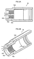
- An angled section 82A is provided at a distal end portion of the pressing member 82 (at the on/off valve 28 side), such that the outer diameter becomes smaller.
- a flat face section 82C which presses the pressing section 28A, is provided at the distal end portion of the pressing member 82, with a step section 82B between the flat face section 82C and the angled section 82A.
- the shape of the angled section 82A is determined such that a gap is formed between the angled section 82A and the opening edge 24 when the screw thread section 78A of the valve adaptor 76 threadedly engages with the screw thread section 22 of the tire valve 16 and is put into the first state (see Fig. 2B ).
- the distal end of the insertion section 60A is disposed close to an upper wall face inside the agent container 18, and the sealing agent 32 in the agent container 18 flows into the pressurized liquid supply chamber 40 via an annular gap between a hole 30A that is formed in the aluminium seal 30 and the insertion section 60A.
- air in the tire 14 may be released until the tire 14 is at the specified pressure.
Abstract

Description
- The present invention relates to a valve adaptor to be attached to a tire valve for supplying a sealing agent and pressurized air into a punctured pneumatic tire, and to a sealing/pump-up device that is equipped with the valve adapter.
- In Patent Reference 1, a sealing/pump-up device is recited that, when a pneumatic tire is punctured, repairs the tire with a sealing agent and pumps up the tire internal pressure to a specified pressure, without the tire and wheel being replaced.
- According to this sealing/pump-up device, a valve adapter provided at a distal end portion of a joint hose is attached to a tire valve of the punctured pneumatic tire, a sealing agent is infused through the joint hose and, thereafter, compressed air is supplied into the tire and the internal pressure of the pneumatic tire is pressurized.
- In this sealing/pump-up device, a depressurization valve is provided at a middle portion of the joint hose. After the compressed air has been supplied into the tire, this depressurization valve may be opened and pressure in the tire adjusted.
- Patent Reference 1: Japanese Patent Application Laid-Open (JP-A) No.
2007-76104 - However, when a depressurization valve provided on a fluid supply hose (the joint hose) is opened, sealing agent that remains in the device may be released together with the air.
An object of the present invention, in consideration of the above circumstances, is to release air in a tire without releasing a sealing agent remaining in a device. - A valve adapter relating to claim 1 of the present invention is a valve adaptor to be provided at a distal end portion of a fluid supply hose of a sealing/pump-up device that, after infusing a sealing agent into a punctured pneumatic tire, supplies compressed air and pressurizes internal pressure of the tire, the valve adaptor being attached to a tire valve of the tire and provided with: a controller that, in a first state in which the valve adapter is threadedly engaged with the tire valve, opens the tire valve and the valve adapter, in a second state in which the valve adapter is loosened from the first state, opens the tire valve and closes the valve adapter, and in a third state in which the valve adapter is loosened from the second state, closes the tire valve and the valve adapter.
- According to the above-described structure, the valve adaptor provided at the distal end portion of the fluid supply hose of a sealing/pump-up device is put into the first state, in which it is threadedly engaged with the tire valve of the punctured pneumatic tire.
- When put into the first state, the controller opens the tire valve and the valve adapter. In this state, the sealing agent is infused into the tire and, after the sealing agent infusion, compressed air is supplied and the internal pressure of the tire is pressurized.
- After the compressed air has been supplied into the tire, when air in the tire is to be released and the internal pressure of the tire adjusted, the valve adapter is loosened and put from the first state into the second state.
- When the valve adapter is put from the first state to the second state, the controller opens the tire valve such that air in the tire is released to the outside, and closes the valve adaptor such that sealing agent and air are not released from the fluid supply hose to the outside.
- Thus, by the controller closing the valve adapter, air in the tire may be released without sealing agent that remains in the sealing/pump-up device being released.
- In a valve adapter relating to claim 2 of the present invention, the controller according to claim 1 is provided with: an outer shell member that threadedly engages with an outer peripheral face of the tire valve; a packing member that is provided in intimate contact with an inner face of the outer shell member, that is in intimate contact with an opening edge of the tire valve in the first state and is separated from the opening edge in the second state and the third state, and at which a through aperture is provided that penetrates from the fluid supply hose side thereof to the tire valve side; a pressing member that penetrates through the through aperture of the packing member and presses an on/off valve provided at the tire valve; an urging member that urges the pressing member toward the tire valve and that, in the first state and the second state, presses the pressing member and opens the on/off valve; an intimate contact section that is provided at an outer face of the pressing member and that, in the second state and the third state, is in intimate contact with the packing member due to pressing force of the pressing member and prevents the sealing agent and air being released to outside from the fluid supply hose; and a releaser that is provided at the outer shell member and releases air released through the tire valve to the outside.
- According to the above-described structure, the packing member is provided in intimate contact with the inner face of the outer shell member that is threadedly engaged with the outer peripheral face of the tire valve.
The packing member is also in intimate contact with the opening edge of the tire valve in the first state, and is separated from the opening edge of the tire valve in the second state and the third state. - The pressing member, which presses the on/off valve provided in the tire valve, penetrates through the through aperture provided in the packing member.
The urging member, which urges the pressing member toward the tire valve, presses the pressing member and opens the on/off valve of the tire valve in the first state and the second state. - In the second state and the third state, the intimate contact member, which is provided at the outer face of the pressing member, is in intimate contact with the packing member due to the pressing force of the urging member, and prevents the sealing agent and air being released to the outside from the fluid supply hose.
- That is, when the valve adapter is put into the second state, the pressing member that is pressed by the urging member opens the on/off valve of the tire valve. Further, because the on/off valve is opened, air released from inside the tire flows between the opening edge of the tire valve and the packing member and is released to the outside by the releaser.
- In the second state, the packing member and the intimate contact section are in intimate contact due to the pressing force of the urging member, and the sealing agent and air are prevented from being released to the outside through the fluid supply hose.
- Thus, by the valve adapter being put into the second state, air in the tire may be released without sealing agent that remains in the sealing/pump-up device being released.
- A valve adapter relating to claim 3 of the present invention is that recited in claim 2, wherein a valve section that spreads outward in radial directions is provided at the on/off valve provided at the tire valve, a protrusion portion that makes intimate contact with the valve section and closes the tire valve is provided at an inner peripheral face of the tire valve, and a valve section urging member that urges the valve section to the protrusion portion and causes the valve section to make intimate contact with the protrusion portion is provided inside the tire valve, and an urging force of the pressing member is stronger than an urging force of the valve section urging member.
- According to the above-described structure, because the urging force of the urging member is stronger than the urging force of the valve section urging member, the tire valve may be opened and the valve adapter closed in the second state, reliably.
- A valve adapter relating to claim 4 of the present invention is that recited in any one of claim 2 and claim 3, wherein a female screw thread section that threadedly engages with a male screw thread section provided at the tire valve is provided at the outer shell member, and the releaser is a through groove section that is provided at the female screw thread section and formed from an opening portion of the outer shell member toward the packing member.
- According to the above-described structure, the female screw thread section that threadedly engages with the male screw thread section of the tire valve is provided at the outer shell member. The releaser is provided at this female screw thread section, and is the through groove section that is formed from the opening portion of the outer shell member toward the packing member.
- Therefore, air in the tire that is released between the opening edge of the tire valve and the packing member is released to the outside through this through groove section.
- A valve adapter relating to claim 5 of the present invention is that recited in any one of claim 2 and claim 3, wherein a female screw thread section that threadedly engages with a male screw thread section provided at the tire valve is provided at the outer shell member, and the releaser is a through hole that penetrates from the female screw thread section to an outer surface of the outer shell member.
- According to the above-described structure, the female screw thread section that threadedly engages with the male screw thread section of the tire valve is provided at the outer shell member. The releaser is the through hole that penetrates from the female screw thread section to the outer face of the outer shell member.
Therefore, air in the tire that is released between the opening edge of the tire valve and the packing member is released to the outside through this through hole. - A sealing/pump-up device relating to claim 6 of the present invention supplies a sealing agent and compressed air into a tire, and is provided with a valve adapter according to any one of claim 1 to claim 5.
- According to the above-described structure, the valve adapter recited in any one of claim 1 to claim 5 is provided at the sealing/pump-up device.
- Therefore, air in the tire may be released and air pressure in the tire adjusted without sealing agent that remains in the sealing/pump-up device being released through the valve adapter.
- According to the present invention, air in a tire may be released without sealing agent remaining in the device being released.
-
-
Fig. 1A is a sectional view showing a valve adapter relating to a first exemplary embodiment of the present invention, and illustrating a second state thereof. -
Fig. 1B is a sectional view showing the valve adapter relating to the first exemplary embodiment of the present invention, and illustrating a third state thereof. -
Fig. 2A is a sectional view showing the valve adapter relating to the first exemplary embodiment of the present invention, and illustrating a state detached from a tire valve. -
Fig. 2B is a sectional view showing the valve adapter relating to the first exemplary embodiment of the present invention, and illustrating a first state thereof. -
Fig. 3A is a sectional view illustrating an outer shell member of the valve adapter relating to the first exemplary embodiment. -
Fig. 3B is a perspective view illustrating the outer shell member of the valve adapter relating to the first exemplary embodiment. -
Fig. 4 is a sectional view illustrating a sealing/pump-up device in which the valve adapter relating to the first exemplary embodiment is employed. -
Fig. 5A and Fig. 5B are sectional views illustrating the sealing/pump-up device in which the valve adapter relating to the first exemplary embodiment is employed. -
Fig. 6 is a perspective view illustrating the sealing/pump-up device in which the valve adapter relating to the first exemplary embodiment is employed. -
Fig. 7A is a sectional view illustrating an outer shell member of a valve adapter relating to a second exemplary embodiment. -
Fig. 7B is a perspective view illustrating the outer shell member of the valve adapter relating to the second exemplary embodiment. - A sealing/pump-up device in which a valve adaptor relating to a first exemplary embodiment of the present invention is employed is described in association with
Fig. 1 to Fig. 6 . - In
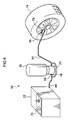
Fig. 6 , a sealing/pump-up device 10 (hereinafter referred to simply as the sealing device), in which avalve adaptor 76 relating to the first exemplary embodiment of the present invention is employed, is illustrated. When a pneumatic tire mounted to a vehicle such as an automobile or the like (hereinafter referred to simply as the tire) is punctured, rather than the tire and a wheel being replaced, the sealingdevice 10 fixes the tire with a sealing agent 32 (seeFig. 5 ) and re-pressurizes (pumps up) the internal pressure to a predetermined standard pressure. - This sealing
device 10 is provided with acompressor unit 12, which serves as an air supplier. A motor, an air pump, a power supply circuit and suchlike are disposed inside thecompressor unit 12, and a power cable (not illustrated), which extends from the power supply circuit to outside the unit, is provided at thecompressor unit 12. A plug provided at a distal end portion of this power supply cable is inserted into, for example, a cigar lighter socket provided in the vehicle. Thus, a power supply may be supplied through the power supply circuit to the motor and the like from a battery mounted in the vehicle. - The
compressor unit 12 is capable of producing pressurized air at a higher pressure than the standard pressures specified for each of types oftire 14 to be fixed by this air pump (for example, 300 kPa or above). - As illustrated in
Fig. 5A , anagent container 18 and aninfusion unit 20 are provided at the sealingdevice 10. Theagent container 18 accommodates the sealingagent 32, and theagent container 18 is welded to theinfusion unit 20. A substantiallytubular outflow port 26, which protrudes downward, is integrally formed at a lower end of theagent container 18. - The
outflow port 26 is formed with a diameter that is thinner than a container main body portion thereabove. Analuminium seal 30, for sealing the sealingagent 32 inside theagent container 18, is provided at an opening region (lower end) of theoutflow port 26. - The
agent container 18 is formed with a raw material thereof being a resin material of a type with gas barrier properties, a metallic material such as an aluminium alloy or the like, or the like. The sealingagent 32 is charged into theagent container 18 in slightly more than a specified amount (for example, 200 g to 400 g) that corresponds to types, sizes and the like of thetire 14 to be fixed by the sealing device 10 (seeFig. 6 ). - In the
agent container 18 of the present exemplary embodiment, as illustrated inFig. 5A , the sealingagent 32 is charged with no gap into theagent container 18, and an empty space is not formed. However, to prevent degeneration due to oxidation, nitriding and the like of the sealingagent 32, a small quantity of an inert gas such as argon or the like may be sealed into theagent container 18 along with the sealingagent 32 at a time of packing. - When the
agent container 18 is put into a standing state with theoutflow port 26 at the top side of theinfusion unit 20 facing downward, the sealingagent 32 in theagent container 18 goes into a state of pressing against thealuminium seal 30 of theagent container 18 due to gravity. - A unit
main body 34 and afoot section 36 are provided at theinfusion unit 20. The unitmain body 34 is formed in a substantially tubular shape. Thefoot section 36 extends to outer periphery sides from a lower end portion of the unitmain body 34. A portion of theoutflow port 26 of theagent container 18 is welded, in a pushed-in state, to an upper portion of the unitmain body 34. - A substantially tubular pressurized
liquid supply chamber 40 is provided in the unitmain body 34. When thealuminium seal 30 is pierced, the pressurizedliquid supply chamber 40 is in fluid communication with the inside of theagent container 18. Specifically, the right side in the drawing relative to the middle of the pressurizedliquid supply chamber 40 is molded to be deeper than the left side in the drawing. - A
jig insertion hole 42 is formed in the middle of theinfusion unit 20. Thejig insertion hole 42 has a circular cross-section extending in a vertical direction from a lower face toward the pressurizedliquid supply chamber 40. - As illustrated in
Fig. 6 , a pressure-resistant hose 44, which extends from thecompressor unit 12, is provided in thesealing device 10. In addition, as illustrated inFig. 5A , apressure pipe 48 is provided in thesealing device 10. Thepressure pipe 48 extends from theinfusion unit 20 and is detachably connected with the pressure-resistant hose 44 via ajoint coupler 46. - A proximal end portion of this pressure-
resistant hose 44 is connected to an air pump in thecompressor unit 12. At a time of operation of the compressor unit 12 (seeFig. 6 ), pressurized air is produced by the air pump and supplied to the pressure-resistant hose 44. A distal end portion of thepressure pipe 48 passes through a peripheral wall section of the unitmain body 34 and opens into a middle portion of thejig insertion hole 42 that extends in the vertical direction. - A
shaft section 50A of a hole-closingmember 50, which closes off thejig insertion hole 42, is inserted into the pressurizedliquid supply chamber 40 side of thejig insertion hole 42. The hole-closingmember 50 is provided with a disc-shaped hole-closingportion 50B, which broadens outward in radial directions, at the upper end of theshaft section 50A.Blades 50C, for making piercing of thealuminium seal 30 easier, are plurally formed at the upper face of the hole-closingportion 50B. - A pair of O-
ring grooves 56 are formed in theshaft section 50A. An O-ring 58 is embedded in each O-ring groove 56.
Theshaft section 50A is wholly inserted into thejig insertion hole 42, and a distal end portion of thepressure pipe 48 is closed off between the O-ring 58 and O-ring 58 of theshaft section 50A. - The
shaft section 50A is held inside thejig insertion hole 42 by frictional force between the O-rings 58 and an inner peripheral surface of thejig insertion hole 42. In this state, the hole-closingportion 50B faces the middle of a front face of thealuminium seal 30, and a small gap is formed between the hole-closingportion 50B and thealuminium seal 30. - A
joint hose 54 that serves as a fluid supply hose is provided in thesealing device 10. Thejoint hose 54 is connected, via an intermediate joining member (not illustrated), with a distal end portion of ajoint section 52. Thejoint section 52 protrudes in a tubular shape in a horizontal direction from the unitmain body 34. Thisjoint hose 54 is a structure that is in fluid communication with the interior of the pressurizedliquid supply chamber 40 via thejoint section 52. - As illustrated in
Fig. 6 , thevalve adaptor 76 is detachably connected, at a distal end portion of thejoint hose 54, to thetire valve 16 of thetire 14. Herein, thevalve adaptor 76 is described in detail later. - Anyway, as illustrated in
Fig. 5B , ajig 60, which is used when the sealingagent 32 is to be discharged from the sealingdevice 10, is provided with a rod-shapedinsertion section 60A and a disc-shapedbase section 60B, which is integrally formed at one end of theinsertion section 60A. - A
first communication channel 62 is formed at a central region in theinsertion section 60A. Thefirst communication channel 62 extends toward the base section from a distal end at the opposite end from the base section.Second communication channels 64 are plurally formed in theinsertion section 60A. Thesecond communication channels 64 penetrate to the outer periphery from the base portion end side of thefirst communication channel 62. Anannular groove 66 is formed in the outer peripheral face of theinsertion section 60A. Thegroove 66 is an air channel at a region of opening of thesecond communication channels 64. A pair of O-ring grooves 68 are formed at the two sides of thegroove 66. O-rings 70 are embedded in the O-ring grooves 68. - A distance L1 from the
base section 60B of thejig 60 to the distal end of thefirst communication channel 62 is set to be shorter than a distance L0 from the lower face of thefoot section 36 of the sealingdevice 10 to an upper wall face of the inside of the agent container 18 (seeFig. 5A ). A distance L3 from thebase section 60B of thejig 60 to the center of thesecond communication channels 64 is set to the same dimension as a distance L4 from the lower face of thefoot section 36 of the sealingdevice 10 to the center of the pressure pipe 48 (seeFig. 5A ). - Next, the
valve adaptor 76, thetire valve 16 and the like are described in association withFig. 1 to Fig. 3 . - As illustrated in
Fig. 2A , ascrew thread section 22, to which thevalve adaptor 76 is to be attached, is provided at an outer peripheral portion of thetubular tire valve 16. Inside thetire valve 16, the on/offvalve 28 is provided, which releases air in the tire through arelease aperture 23 of thetire valve 16 when pressed. - In detail, the on/off
valve 28 is formed in a rod shape extending in the length direction of thetire valve 16, and is provided with apressing section 28A and a protrudingvalve section 28B. Thepressing section 28A is pressed by a pressingmember 82, which will be described later. Thevalve section 28B makes intimate contact with aprotrusion portion 16A provided inside thetire valve 16 and shuts air in thetire 14. - A distal end portion of a
coil spring 38, which urges thevalve section 28B so as to be in intimate contact with theprotrusion portion 16A, abuts against thevalve section 28B. - A
stopper section 16B is provided inside thetire valve 16. When the on/offvalve 28 is pressed by the pressingmember 82 and thevalve section 28B moves so as to compress thecoil spring 38, thestopper section 16B abuts against the on/offvalve 28 and limits movement of the on/offvalve 28. - Meanwhile, a tubular
outer shell member 78 with a step is provided at thevalve adaptor 76. Ascrew thread section 78A, which threadedly engages with thescrew thread section 22 of thetire valve 16, is provided at an inner peripheral face of theouter shell member 78. - A
step section 78B is provided at a rear end (deeper side end portion) of thescrew thread section 78A, so as to increase an internal diameter of theouter shell member 78. Atubular packing member 80 is provided inside theouter shell member 78 so as to be in intimate contact with thestep section 78B and also such that an outer peripheral face thereof is in intimate contact with the inner peripheral face of theouter shell member 78. An inner diameter of the packingmember 80 is determined such that an end face of the packingmember 80 is in intimate contact with the openingedge 24 of thetire valve 16 when thescrew thread section 78A of thevalve adaptor 76 is threadedly engaged with thescrew thread section 22 of thetire valve 16 and put into a first state (seeFig. 2A ). - A through
aperture 80A is provided at a central portion of the packingmember 80. The throughaperture 80A passes through thejoint hose 54 side (seeFig. 6 ) and thetire valve 16 side. The cylindrical pressingmember 82 is disposed at the central portion of the packingmember 80 so as to pass through the throughaperture 80A with a gap between the pressingmember 82 and the packingmember 80. - An
angled section 82A is provided at a distal end portion of the pressing member 82 (at the on/offvalve 28 side), such that the outer diameter becomes smaller. Aflat face section 82C, which presses thepressing section 28A, is provided at the distal end portion of the pressingmember 82, with astep section 82B between theflat face section 82C and theangled section 82A. The shape of theangled section 82A is determined such that a gap is formed between theangled section 82A and the openingedge 24 when thescrew thread section 78A of thevalve adaptor 76 threadedly engages with thescrew thread section 22 of thetire valve 16 and is put into the first state (seeFig. 2B ). - Meanwhile, a distal end portion of a
coil spring 84, which serves as an urging member that urges the pressingmember 82 toward thetire valve 16, abuts against a rear end portion of the pressingmember 82. At a fixedmember 86, a largediameter tube section 86A, which is fixed to the inner peripheral face of theouter shell member 78, is connected with a smalldiameter tube section 86B. Thecoil spring 84 is disposed inside the largediameter tube section 86A of the fixedmember 86. A rear end portion of thecoil spring 84 abuts against astep section 86C, which connects the largediameter tube section 86A with the smalldiameter tube section 86B. - A protruding
intimate contact section 88 is provided at the outer peripheral face of the pressingmember 82 so as to encircle the outer peripheral face. Theintimate contact section 88 and the packingmember 80 are put into intimate contact by the urging force of thecoil spring 84. - A spring constant K1 of the
coil spring 84 is set to be larger than a spring constant K2 of thecoil spring 38 that urges the on/offvalve 28. - That is, in the first state in which the
valve adaptor 76 is attached to the tire valve 16 (seeFig. 2B ), the on/offvalve 28 is pressed by the pressingmember 82 that is pressed by thecoil spring 84, thecoil spring 38 is compressed, and thevalve section 28B is separated from thetire valve 16. - In the first state illustrated in
Fig. 2B , the on/offvalve 28, of which thevalve section 28B moves away from theprotrusion portion 16A, abuts against thestopper section 16B and the on/offvalve 28 is stopped. Because the on/offvalve 28 is stopped, the pressingmember 82 is pressed by the on/offvalve 28, thecoil spring 84 compresses, and theintimate contact section 88 and the packingmember 80 separate. - Meanwhile, as illustrated in
Fig. 3 , a throughgroove section 78D is provided at thescrew thread section 78A of theouter shell member 78, so as to cut across thescrew thread section 78A from anopening portion 78C of theouter shell member 78 toward the packing member 80 (seeFig. 2 ), to serve as a releaser. - With this structure, as illustrated in
Fig. 2A , in a state in which thevalve adaptor 76 is detached from thetire valve 16, thevalve section 28B of thetire valve 16 is urged by thecoil spring 38 and makes intimate contact with theprotrusion portion 16A. Therefore, thetire valve 16 closes such that air in thetire 14 is not released to the outside. - Further, the
intimate contact section 88 provided at the outer peripheral face of the pressingmember 82 is in intimate contact with the packingmember 80 due to the urging force of thecoil spring 84. Therefore, thevalve adaptor 76 closes such that the sealing agent and air or the like are not released to the outside through the joint hose 54 (seeFig. 6 ). - Thus, in the state in which the
valve adaptor 76 is detached from thetire valve 16, thetire valve 16 and thevalve adaptor 76 are closed. - In the first state, in which, as illustrated in
Fig. 2B , thescrew thread section 78A provided at thevalve adaptor 76 threadedly engages with thescrew thread section 22 provided at thetire valve 16 and thevalve adaptor 76 is attached to thetire valve 16, thepressing section 28A of the on/offvalve 28 of thetire valve 16 is pressed by the pressingmember 82, thecoil spring 38 compresses, and thevalve section 28B of the on/offvalve 28 and theprotrusion portion 16A are separated. Therefore, thetire valve 16 opens such that air in thetire 14 is in fluid communication with the outside. - When the pressing
member 82 presses the on/offvalve 28, the on/offvalve 28 abuts against thestopper section 16B, and the on/offvalve 28 stops. The stopped on/offvalve 28 abuts against the pressingmember 82 and thecoil spring 84 is compressed. By thecoil spring 84 being compressed, theintimate contact section 88 provided at the outer peripheral face of the pressingmember 82 is separated from the packingmember 80. - Therefore, sealing agent and air that have passed through the inside of the fixed
member 86 pass between theintimate contact section 88 and the packingmember 80 as shown by the arrows in the drawings, further pass between the pressingmember 82 and the packingmember 80, still further pass between theangled section 82A of the pressingmember 82 and the openingedge 24, and are released to the outside. That is, thevalve adaptor 76 is opened. - Because the opening
edge 24 of thetire valve 16 and the packingmember 80 are in intimate contact, the sealing agent and air flowing from thevalve adaptor 76 are not leaked to the outside. - Thus, the
tire valve 16 and thevalve adaptor 76 are opened, and the openingedge 24 and the packingmember 80 are put into intimate contact. Thus, the sealing agent and air flowing from thevalve adaptor 76 may be supplied through thetire valve 16 into thetire 14 as shown by the arrows in the drawings, without leaking to the outside. - As illustrated in
Fig. 1A , when theouter shell member 78 is turned and thevalve adaptor 76 is loosened and put from the first state (seeFig. 2B ) into the second state, because the spring constant K1 of thecoil spring 84 is set to be larger than the spring constant K2 of thecoil spring 38 as mentioned above, thecoil spring 84 extends, thepressing section 28A of the on/offvalve 28 of thetire valve 16 is pressed by the pressingmember 82, and the state in which thevalve section 28B of the on/offvalve 28 and theprotrusion portion 16A are separated is maintained. Hence, thetire valve 16 is opened such that air in thetire 14 is released to the outside. - By the
outer shell member 78 being moved in a direction away from the tire valve 16 (the direction of arrow A), the packingmember 80 is moved in a direction approaching theintimate contact section 88. Thecoil spring 84 extends as mentioned above, and urges theintimate contact section 88 against the packingmember 80, putting them into intimate contact. Therefore, thevalve adaptor 76 closes such that sealing agent and air are not released to the outside through the joint hose 54 (seeFig. 6 ). - By the packing
member 80 moving in the direction of arrow A, the openingedge 24 of thetire valve 16 and the packingmember 80 are separated. - Thus, by the
valve adaptor 76 being put into the second state, thetire valve 16 is opened and thevalve adaptor 76 is closed, and the openingedge 24 and the packingmember 80 are separated. Therefore, air in thetire 14 is released through thetire valve 16 as shown by the arrows in the drawing, flows between the openingedge 24 and the packingmember 80, and is released to the outside through the throughgroove section 78D provided in thescrew thread section 78A of theouter shell member 78, which is illustrated inFig. 3 . - As illustrated in
Fig. 1B , when theouter shell member 78 is turned and thevalve adaptor 76 is loosened and put from the second state (seeFig. 1A ) into the third state, in association with theouter shell member 78 moving in the direction of arrow A away from thetire valve 16, the pressingmember 82 is pressed by the packingmember 80 and also moves in the direction of arrow A. - Because the pressing
member 82 moves in the direction of arrow A, thevalve section 28B of thetire valve 16 makes intimate contact with theprotrusion portion 16A due to the urging force of thecoil spring 38. Therefore, thetire valve 16 closes. - Meanwhile, the
valve adaptor 76 maintains the state of intimate contact between the packingmember 80 and theintimate contact section 88. Therefore, theclosed valve adaptor 76 is kept in this state.
Thus, thetire valve 16 and thevalve adaptor 76 close up. - Next, an operational procedure of repairing the punctured
tire 14 using thesealing device 10 relating to the present exemplary embodiment is described. - As illustrated in
Fig. 6 , when a puncture has occurred in thetire 14, firstly, an operator screws thevalve adaptor 76 of thejoint hose 54 onto thetire valve 16 of thetire 14, and puts the pressurized liquid supply chamber 40 (seeFig. 5A ) into fluid communication with the interior of thetire 14 through thejoint hose 54. - Specifically, in the first state as illustrated in
Fig. 2B , the pressingmember 82 provided at thevalve adaptor 76 presses against thepressing section 28A of the on/offvalve 28 of thetire valve 16 and separates thevalve section 28B and theprotrusion portion 16A. Thus, thetire valve 16 opens. - The on/off
valve 28, which is stopped by thestopper section 16B, presses against the pressingmember 82 and compresses thecoil spring 84. Therefore, the packingmember 80 and theintimate contact section 88 provided at the outer peripheral face of the pressingmember 82 separate, and thevalve adaptor 76 opens. - Thus, by the
tire valve 16 and thevalve adaptor 76 opening, the pressurized liquid supply chamber 40 (seeFig. 5A ) is put into fluid communication with the interior of thetire 14 through thejoint hose 54. - Then, the operator inserts the
insertion section 60A of thejig 60 illustrated inFig. 5B into thejig insertion hole 42 of the sealingdevice 10 illustrated inFig. 5A , and thebase section 60B of thejig 60 penetrates into thefoot section 36 of the sealingdevice 10. - As illustrated in
Fig. 4 , the hole-closingportion 50B of the hole-closingmember 50, which is pushed by theinsertion section 60A, breaks through thealuminium seal 30 and is pushed into the interior of theagent container 18, and theinsertion section 60A advances into the interior of theagent container 18. Thereafter, the sealingdevice 10 is disposed on, for example, a road surface, such that thefoot section 36 is below and theagent container 18 is above. - When the
insertion section 60A of thejig 60 is inserted into thejig insertion hole 42 of the sealingdevice 10, the distal end of theinsertion section 60A is disposed close to an upper wall face inside theagent container 18, and the sealingagent 32 in theagent container 18 flows into the pressurizedliquid supply chamber 40 via an annular gap between ahole 30A that is formed in thealuminium seal 30 and theinsertion section 60A. Therefore, aspace 72 is formed at an upper portion of the interior of theagent container 18, corresponding to a volume of the sealingagent 32 that flows out into the pressurizedliquid supply chamber 40, and an end portion of thefirst communication channel 62 that opens at the distal end of theinsertion section 60A may be disposed at the upper side relative to the liquid surface of the sealingagent 32. - Then the
compressor unit 12 is operated, while theinfusion unit 20 and theagent container 18 are retained such that theagent container 18 is disposed above theinfusion unit 20. Pressurized air produced by thecompressor unit 12 is supplied to theagent container 18 via the pressure-resistant hose 44, thepressure pipe 48, thesecond communication channels 64 of thejig 60 and thefirst communication channel 62. As mentioned above, the end portion of thefirst communication channel 62 is disposed at the upper side relative to the liquid surface of the sealingagent 32. Therefore, the pressurized air does not form bubbles and ascend within the sealingagent 32. - When the pressurized air is supplied to the
agent container 18, the volume of thespace 72 formed at the upper portion of theagent container 18 expands and pressurizes the sealingagent 32, and thepressurized sealing agent 32 flows through the annular gap between thehole 30A formed in thealuminium seal 30 and theinsertion section 60A, and is supplied through the pressurizedliquid supply chamber 40, thejoint hose 54 and the valve adaptor 76 (seeFig. 6 ) into thetire 14. - After all the sealing
agent 32 in theagent container 18 has been drained, the sealingagent 32 in the pressurizedliquid supply chamber 40 is pressurized and is supplied through thejoint hose 54 into thetire 14. - Thereafter, when the sealing
agent 32 has been discharged from the sealingdevice 10, the pressurized air is supplied into thetire 14 via theagent container 18, the pressurizedliquid supply chamber 40 and thejoint hose 54 so as to be slightly higher than the specified pressure. - Then, as illustrated in
Fig. 1A , the operator turns theouter shell member 78 and loosens thevalve adaptor 76, putting it from the first state (seeFig. 2B ) to the second state. - When the valve adapter is put into the second state, as described above, the
valve adaptor 76 is closed, and air in thetire 14 is released through thetire valve 16, flows between the openingedge 24 and the packingmember 80, and is released to the outside through the throughgroove section 78D provided in thescrew thread section 78A of theouter shell member 78, which is illustrated inFig. 3 . - Thus, air in the
tire 14 may be released until thetire 14 is at the specified pressure. - When checking the internal pressure of the
tire 14 with a pressure gauge 74 (seeFig. 6 ) that is provided at thecompressor unit 12, the operator may check the internal pressure of thetire 14 with thepressure gauge 74 by again attaching thevalve adaptor 76 to thetire valve 16. - Thus, because air in the
tire 14 may be released in the state in which thevalve adaptor 76 is closed, the air in thetire 14 may be released and the air pressure of thetire 14 adjusted without releasing sealing agent that remains in thesealing device 10. - Next, a sealing device in which a valve adaptor relating to a second exemplary embodiment of the present invention is employed is described in association with
Fig. 7 .
Herein, members that are the same as in the first exemplary embodiment are assigned the same reference numerals and descriptions thereof are not given. - In this exemplary embodiment, a through groove section is not provided at an
outer shell member 90. Instead, throughholes 90C provided at the rearward of ascrew thread section 90A (an end portion at an opposite side thereof from anopening portion 90B). The throughholes 90C penetrate from thescrew thread section 90A to an outer surface of theouter shell member 90. - Thus, in the second state of the
valve adaptor 76, air released through thetire valve 16 from the interior of the tire flows through the throughholes 90C and is released to the outside. -
- 10
- Sealing device (sealing/pump-up device)
- 14
- Tire
- 16
- Tire valve
- 22
- Screw thread section (male screw thread section)
- 54
- Joint hose (fluid supply hose)
- 76
- Valve adaptor
- 78
- Outer shell member
- 78A
- Screw thread section (female screw thread section)
- 78D
- Through groove section
- 80
- Packing member
- 82
- Pressing member
- 84
- Coil spring (urging member)
- 88
- Intimate contact section
- 90
- Outer shell member
- 90A
- Screw thread section (female screw thread section)
- 90C
- Through holes
Claims (6)
- A valve adaptor provided at a distal end portion of a fluid supply hose of a sealing/pump-up device that, after infusing a sealing agent into a punctured pneumatic tire, supplies compressed air and pressurizes internal pressure of the tire, the valve adaptor being attached to a tire valve of the tire, and comprising:a controller that,
in a first state in which the valve adapter is threadedly engaged with the tire valve, opens the tire valve and the valve adapter,
in a second state in which the valve adapter is loosened from the first state, opens the tire valve and closes the valve adapter, and
in a third state in which the valve adapter is loosened from the second state, closes the tire valve and the valve adapter. - The valve adaptor according to claim 1, wherein the controller comprises:an outer shell member that threadedly engages with an outer peripheral face of the tire valve;a packing member that is provided in intimate contact with an inner face of the outer shell member, that is in intimate contact with an opening edge of the tire valve in the first state and is separated from the opening edge in the second state and the third state, and at which a through aperture is provided that penetrates from the fluid supply hose side thereof to the tire valve side;a pressing member that penetrates through the through aperture of the packing member and presses an on/off valve provided at the tire valve;an urging member that urges the pressing member toward the tire valve and that, in the first state and the second state, presses the pressing member and opens the on/off valve;an intimate contact section that is provided at an outer face of the pressing member and that, in the second state and the third state, is in intimate contact with the packing member due to pressing force of the urging member and prevents the sealing agent and air being released to outside from the fluid supply hose; anda releaser that is provided at the outer shell member and releases air released through the tire valve to the outside.
- The valve adaptor according to claim 2, wherein
a valve section that spreads outward in radial directions is provided at the on/off valve provided at the tire valve, a protrusion portion that makes intimate contact with the valve section and closes the tire valve is provided at an inner peripheral face of the tire valve, and a valve section urging member that urges the valve section to the protrusion portion and causes the valve section to make intimate contact with the protrusion portion is provided inside the tire valve, and
an urging force of the urging member is stronger than an urging force of the valve section urging member. - The valve adaptor according to any one of claim 2 and claim 3, wherein
a female screw thread section that threadedly engages with a male screw thread section provided at the tire valve is provided at the outer shell member, and
the releaser is a through groove section that is provided at the female screw thread section and formed from an opening portion of the outer shell member toward the packing member. - The valve adaptor according to any one of claim 2 and claim 3, wherein
a female screw thread section that threadedly engages with a male screw thread section provided at the tire valve is provided at the outer shell member, and
the releaser is a through hole that penetrates from the female screw thread section to an outer surface of the outer shell member. - A sealing/pump-up device, wherein the sealing/pump-up device supplies a sealing agent and compressed air into a tire, and includes a valve adapter according to any one of claim 1 to claim 5.
Applications Claiming Priority (2)
| Application Number | Priority Date | Filing Date | Title |
|---|---|---|---|
| JP2007196244A JP4927657B2 (en) | 2007-07-27 | 2007-07-27 | Valve adapter and sealing / pump-up device provided with the same |
| PCT/JP2008/063168 WO2009017000A1 (en) | 2007-07-27 | 2008-07-23 | Valve adaptor and sealing/pump-up device with the same |
Publications (3)
| Publication Number | Publication Date |
|---|---|
| EP2186628A1 true EP2186628A1 (en) | 2010-05-19 |
| EP2186628A4 EP2186628A4 (en) | 2013-12-04 |
| EP2186628B1 EP2186628B1 (en) | 2017-04-19 |
Family
ID=40304232
Family Applications (1)
| Application Number | Title | Priority Date | Filing Date |
|---|---|---|---|
| EP08778333.8A Not-in-force EP2186628B1 (en) | 2007-07-27 | 2008-07-23 | Valve adaptor and sealing/pump-up device with the same |
Country Status (3)
| Country | Link |
|---|---|
| EP (1) | EP2186628B1 (en) |
| JP (1) | JP4927657B2 (en) |
| WO (1) | WO2009017000A1 (en) |
Cited By (19)
| Publication number | Priority date | Publication date | Assignee | Title |
|---|---|---|---|---|
| ITTO20100379A1 (en) * | 2010-05-06 | 2011-11-07 | Tek Global Srl | CONTAINER FOR A SEALANT LIQUID FOR THE REPAIR OF INFLATABLE ITEMS |
| US20120231100A1 (en) * | 2011-03-10 | 2012-09-13 | Wen San Chou | Device for sealing and inflating inflatable object |
| WO2013113215A1 (en) * | 2012-02-02 | 2013-08-08 | 冠翔(香港)工业有限公司 | Supply apparatus for integrating gas and rubber compound |
| EP2657008A1 (en) * | 2012-04-27 | 2013-10-30 | Wen-San Jhou | Vehicle-carried air compressor device |
| US8978717B2 (en) | 2011-09-28 | 2015-03-17 | Sumitomo Rubber Industries, Ltd. | Cap unit for puncture repair |
| US9333715B2 (en) | 2011-09-30 | 2016-05-10 | Sumitomo Rubber Industries, Ltd. | Cap unit for puncture repair |
| WO2017092900A1 (en) * | 2015-12-03 | 2017-06-08 | Continental Reifen Deutschland Gmbh | Device for sealing and inflating motor vehicle tyres |
| FR3061085A3 (en) * | 2016-12-27 | 2018-06-29 | Michelin & Cie | ADAPTER FOR PNEUMATIC VALVE |
| DE102012108502B4 (en) | 2011-11-02 | 2018-11-29 | Wen-San Jhou | Air compression device for carrying in a vehicle |
| WO2019023758A1 (en) * | 2017-08-03 | 2019-02-07 | Trydel Research Pty Ltd | Improvements to tire repair apparatus |
| CN109958602A (en) * | 2017-12-25 | 2019-07-02 | 已久工业股份有限公司 | The non-return joint structure of the concatenation hose of vehicle-mounted air compressor |
| EP3496937A4 (en) * | 2016-08-15 | 2020-04-08 | Consumer Products International LLC | Currency operated tire inflation and repair apparatus and methods |
| WO2020097921A1 (en) * | 2018-11-16 | 2020-05-22 | 冠翔(香港)工业有限公司 | Pipe connector assembly and tire maintenance apparatus having same |
| EP3797977A1 (en) * | 2019-09-12 | 2021-03-31 | Wen-San Chou | Anti-spray joint structure for connection of air nozzle of tire and connection hose of air compressor |
| EP3797980A1 (en) * | 2019-09-24 | 2021-03-31 | Wen-San Chou | Check joint structure for connection of air nozzle of tire and connector of connection hose of air compressor |
| EP3797979A1 (en) * | 2019-09-24 | 2021-03-31 | Wen-San Chou | Check joint structure for connection of air nozzle of tire and connection hose of air compressor |
| EP3797981A1 (en) * | 2019-09-25 | 2021-03-31 | Wen-San Chou | Check structure for connection of air nozzle of tire and connection hose of air compressor |
| EP3797978A1 (en) * | 2019-09-12 | 2021-03-31 | Wen-San Chou | Anti-spray structure for connection of air nozzle of tire of vehicle and connection hose of air compressor |
| EP4169745A1 (en) * | 2021-10-19 | 2023-04-26 | Continental Reifen Deutschland GmbH | Tyre connection valve device for connecting a puncture aid set to a tyre valve and puncture aid set with such a device |
Families Citing this family (4)
| Publication number | Priority date | Publication date | Assignee | Title |
|---|---|---|---|---|
| HK1172204A2 (en) * | 2011-08-12 | 2013-04-05 | Active Tools Int Hk Ltd | Auto decompression valve |
| KR101515576B1 (en) * | 2013-09-24 | 2015-04-30 | 박춘길 | The air pouring apparatus |
| KR200476261Y1 (en) | 2013-09-27 | 2015-02-12 | 이규석 | Portable Device for Pumping Air into Tire |
| CN117030138B (en) * | 2023-08-08 | 2024-02-13 | 芜湖佳宏新材料股份有限公司 | Tightness detection device and detection method for photoelectric signal communication connector |
Citations (4)
| Publication number | Priority date | Publication date | Assignee | Title |
|---|---|---|---|---|
| GB933118A (en) * | 1960-11-28 | 1963-08-08 | Universal Aero Tech Corp | Improvements in or relating to a combined puncture sealer and tire inflater |
| JPS5241517U (en) * | 1975-09-19 | 1977-03-24 | ||
| US4276898A (en) * | 1980-01-30 | 1981-07-07 | Stop-A-Flat Corporation | Delivery system for pneumatic vessels |
| JP2007182036A (en) * | 2006-01-10 | 2007-07-19 | Bridgestone Corp | Connector and connector set |
Family Cites Families (2)
| Publication number | Priority date | Publication date | Assignee | Title |
|---|---|---|---|---|
| DE19652546B4 (en) * | 1996-12-17 | 2012-11-22 | Sumitomo Rubber Industries Ltd. | Means for sealing tires during breakdowns, devices for sealing and inflating tires and tires with integrated sealing means |
| JP2007076104A (en) * | 2005-09-13 | 2007-03-29 | Bridgestone Corp | Sealing pump-up device |
-
2007
- 2007-07-27 JP JP2007196244A patent/JP4927657B2/en not_active Expired - Fee Related
-
2008
- 2008-07-23 WO PCT/JP2008/063168 patent/WO2009017000A1/en active Application Filing
- 2008-07-23 EP EP08778333.8A patent/EP2186628B1/en not_active Not-in-force
Patent Citations (4)
| Publication number | Priority date | Publication date | Assignee | Title |
|---|---|---|---|---|
| GB933118A (en) * | 1960-11-28 | 1963-08-08 | Universal Aero Tech Corp | Improvements in or relating to a combined puncture sealer and tire inflater |
| JPS5241517U (en) * | 1975-09-19 | 1977-03-24 | ||
| US4276898A (en) * | 1980-01-30 | 1981-07-07 | Stop-A-Flat Corporation | Delivery system for pneumatic vessels |
| JP2007182036A (en) * | 2006-01-10 | 2007-07-19 | Bridgestone Corp | Connector and connector set |
Non-Patent Citations (1)
| Title |
|---|
| See also references of WO2009017000A1 * |
Cited By (33)
| Publication number | Priority date | Publication date | Assignee | Title |
|---|---|---|---|---|
| ITTO20100379A1 (en) * | 2010-05-06 | 2011-11-07 | Tek Global Srl | CONTAINER FOR A SEALANT LIQUID FOR THE REPAIR OF INFLATABLE ITEMS |
| TWI482908B (en) * | 2011-03-07 | 2015-05-01 | Wen San Chou | Air compressor for vehicle |
| US20120231100A1 (en) * | 2011-03-10 | 2012-09-13 | Wen San Chou | Device for sealing and inflating inflatable object |
| CN102673533A (en) * | 2011-03-10 | 2012-09-19 | 周文三 | Air compressor device for vehicle |
| EP2497630A3 (en) * | 2011-03-10 | 2012-11-21 | Wen-San Jhou | Device for sealing and inflating inflatable object |
| US8627857B2 (en) * | 2011-03-10 | 2014-01-14 | Wen San Chou | Device for sealing and inflating inflatable object |
| CN102673533B (en) * | 2011-03-10 | 2015-04-08 | 周文三 | Air compressor device for vehicle |
| US8978717B2 (en) | 2011-09-28 | 2015-03-17 | Sumitomo Rubber Industries, Ltd. | Cap unit for puncture repair |
| US9333715B2 (en) | 2011-09-30 | 2016-05-10 | Sumitomo Rubber Industries, Ltd. | Cap unit for puncture repair |
| DE102012108502B4 (en) | 2011-11-02 | 2018-11-29 | Wen-San Jhou | Air compression device for carrying in a vehicle |
| WO2013113215A1 (en) * | 2012-02-02 | 2013-08-08 | 冠翔(香港)工业有限公司 | Supply apparatus for integrating gas and rubber compound |
| EP2657008A1 (en) * | 2012-04-27 | 2013-10-30 | Wen-San Jhou | Vehicle-carried air compressor device |
| WO2017092900A1 (en) * | 2015-12-03 | 2017-06-08 | Continental Reifen Deutschland Gmbh | Device for sealing and inflating motor vehicle tyres |
| CN108290358A (en) * | 2015-12-03 | 2018-07-17 | 大陆轮胎德国有限公司 | Device for being sealed and inflating to motor vehicle tire |
| CN108290358B (en) * | 2015-12-03 | 2020-06-23 | 大陆轮胎德国有限公司 | Device for sealing and inflating a motor vehicle tyre |
| US10556392B2 (en) | 2015-12-03 | 2020-02-11 | Continental Reifen Deutschland Gmbh | Apparatus for sealing and inflating motor vehicle tires |
| EP3496937A4 (en) * | 2016-08-15 | 2020-04-08 | Consumer Products International LLC | Currency operated tire inflation and repair apparatus and methods |
| FR3061085A3 (en) * | 2016-12-27 | 2018-06-29 | Michelin & Cie | ADAPTER FOR PNEUMATIC VALVE |
| WO2019023758A1 (en) * | 2017-08-03 | 2019-02-07 | Trydel Research Pty Ltd | Improvements to tire repair apparatus |
| CN109958602A (en) * | 2017-12-25 | 2019-07-02 | 已久工业股份有限公司 | The non-return joint structure of the concatenation hose of vehicle-mounted air compressor |
| CN109958602B (en) * | 2017-12-25 | 2021-07-20 | 已久工业股份有限公司 | Check joint structure of serially connected hose of vehicle-mounted air compressor |
| EP3505334A1 (en) * | 2017-12-25 | 2019-07-03 | UNIK World Industrial Co., Ltd. | Combination structure for a hose connected between an air compressor and a tire |
| US11904817B2 (en) | 2018-11-16 | 2024-02-20 | Active Tools International (Hk) Ltd. | Pipe connector assembly and tire maintenance apparatus having same |
| CN113165606B (en) * | 2018-11-16 | 2024-02-06 | 冠翔(香港)工业有限公司 | Pipe joint assembly and tire maintenance equipment comprising same |
| EP3882090A4 (en) * | 2018-11-16 | 2022-07-13 | Active Tools International (HK) Ltd. | Pipe connector assembly and tire maintenance apparatus having same |
| CN113165606A (en) * | 2018-11-16 | 2021-07-23 | 冠翔(香港)工业有限公司 | Pipe joint assembly and tire maintenance equipment comprising same |
| WO2020097921A1 (en) * | 2018-11-16 | 2020-05-22 | 冠翔(香港)工业有限公司 | Pipe connector assembly and tire maintenance apparatus having same |
| EP3797978A1 (en) * | 2019-09-12 | 2021-03-31 | Wen-San Chou | Anti-spray structure for connection of air nozzle of tire of vehicle and connection hose of air compressor |
| EP3797977A1 (en) * | 2019-09-12 | 2021-03-31 | Wen-San Chou | Anti-spray joint structure for connection of air nozzle of tire and connection hose of air compressor |
| EP3797979A1 (en) * | 2019-09-24 | 2021-03-31 | Wen-San Chou | Check joint structure for connection of air nozzle of tire and connection hose of air compressor |
| EP3797980A1 (en) * | 2019-09-24 | 2021-03-31 | Wen-San Chou | Check joint structure for connection of air nozzle of tire and connector of connection hose of air compressor |
| EP3797981A1 (en) * | 2019-09-25 | 2021-03-31 | Wen-San Chou | Check structure for connection of air nozzle of tire and connection hose of air compressor |
| EP4169745A1 (en) * | 2021-10-19 | 2023-04-26 | Continental Reifen Deutschland GmbH | Tyre connection valve device for connecting a puncture aid set to a tyre valve and puncture aid set with such a device |
Also Published As
| Publication number | Publication date |
|---|---|
| WO2009017000A1 (en) | 2009-02-05 |
| JP2009029036A (en) | 2009-02-12 |
| EP2186628A4 (en) | 2013-12-04 |
| EP2186628B1 (en) | 2017-04-19 |
| JP4927657B2 (en) | 2012-05-09 |
Similar Documents
| Publication | Publication Date | Title |
|---|---|---|
| EP2186628B1 (en) | Valve adaptor and sealing/pump-up device with the same | |
| EP2030768B1 (en) | Sealing pump-up device | |
| US8201586B2 (en) | Sealing pump-up device | |
| CN100586812C (en) | Container for conservation and injection of sealant | |
| CN101316696B (en) | Sealing/pump-up device | |
| JP2007168418A (en) | Sealing pumping up apparatus of tire | |
| EP2497629A1 (en) | Puncture repair kit | |
| JP2008307861A (en) | Sealing pump-up apparatus | |
| EP2305570A1 (en) | Structure for preventing dislocation of container, and sealing pump-up device | |
| CN101730619B (en) | Tire sealing device | |
| JP4908973B2 (en) | Sealing / pump-up device | |
| JP2007076104A (en) | Sealing pump-up device | |
| JP2008155929A (en) | Sealant injecting method | |
| JP2006117193A (en) | Sealing pump-up device | |
| JP2008175345A (en) | Valve connector | |
| JP4704862B2 (en) | Tire sealing and pump-up equipment | |
| JP2008023909A (en) | Sealing pump-up apparatus | |
| JP4244313B2 (en) | Sealing / pump-up device and adapter | |
| JP6021266B2 (en) | Fluidity repair material injector | |
| JP2011131547A (en) | Sealing and pumping-up device | |
| JP5798591B2 (en) | Tire puncture repair kit | |
| JP2008162070A (en) | Sealing pump-up device | |
| JP2007090575A (en) | Puncture repairing apparatus of tire | |
| JP2007076105A (en) | Sealing pump-up device | |
| JP2010036532A (en) | Sealing pumping-up apparatus |
Legal Events
| Date | Code | Title | Description |
|---|---|---|---|
| PUAI | Public reference made under article 153(3) epc to a published international application that has entered the european phase |
Free format text: ORIGINAL CODE: 0009012 |
|
| 17P | Request for examination filed |
Effective date: 20100226 |
|
| AK | Designated contracting states |
Kind code of ref document: A1 Designated state(s): AT BE BG CH CY CZ DE DK EE ES FI FR GB GR HR HU IE IS IT LI LT LU LV MC MT NL NO PL PT RO SE SI SK TR |
|
| AX | Request for extension of the european patent |
Extension state: AL BA MK RS |
|
| DAX | Request for extension of the european patent (deleted) | ||
| A4 | Supplementary search report drawn up and despatched |
Effective date: 20131104 |
|
| RIC1 | Information provided on ipc code assigned before grant |
Ipc: F16K 15/20 20060101ALI20131028BHEP Ipc: B60S 5/04 20060101ALI20131028BHEP Ipc: B29C 73/02 20060101AFI20131028BHEP |
|
| REG | Reference to a national code |
Ref country code: DE Ref legal event code: R079 Ref document number: 602008049860 Country of ref document: DE Free format text: PREVIOUS MAIN CLASS: B29C0073020000 Ipc: B29C0073160000 |
|
| GRAP | Despatch of communication of intention to grant a patent |
Free format text: ORIGINAL CODE: EPIDOSNIGR1 |
|
| RIC1 | Information provided on ipc code assigned before grant |
Ipc: B60S 5/04 20060101ALI20161007BHEP Ipc: B29L 30/00 20060101ALN20161007BHEP Ipc: F16K 15/20 20060101ALI20161007BHEP Ipc: B29C 73/16 20060101AFI20161007BHEP |
|
| INTG | Intention to grant announced |
Effective date: 20161027 |
|
| GRAS | Grant fee paid |
Free format text: ORIGINAL CODE: EPIDOSNIGR3 |
|
| GRAA | (expected) grant |
Free format text: ORIGINAL CODE: 0009210 |
|
| AK | Designated contracting states |
Kind code of ref document: B1 Designated state(s): AT BE BG CH CY CZ DE DK EE ES FI FR GB GR HR HU IE IS IT LI LT LU LV MC MT NL NO PL PT RO SE SI SK TR |
|
| REG | Reference to a national code |
Ref country code: GB Ref legal event code: FG4D |
|
| REG | Reference to a national code |
Ref country code: CH Ref legal event code: EP |
|
| REG | Reference to a national code |
Ref country code: AT Ref legal event code: REF Ref document number: 885534 Country of ref document: AT Kind code of ref document: T Effective date: 20170515 |
|
| REG | Reference to a national code |
Ref country code: IE Ref legal event code: FG4D |
|
| REG | Reference to a national code |
Ref country code: DE Ref legal event code: R096 Ref document number: 602008049860 Country of ref document: DE |
|
| REG | Reference to a national code |
Ref country code: FR Ref legal event code: PLFP Year of fee payment: 10 |
|
| REG | Reference to a national code |
Ref country code: NL Ref legal event code: MP Effective date: 20170419 |
|
| REG | Reference to a national code |
Ref country code: LT Ref legal event code: MG4D |
|
| REG | Reference to a national code |
Ref country code: AT Ref legal event code: MK05 Ref document number: 885534 Country of ref document: AT Kind code of ref document: T Effective date: 20170419 |
|
| PG25 | Lapsed in a contracting state [announced via postgrant information from national office to epo] |
Ref country code: NL Free format text: LAPSE BECAUSE OF FAILURE TO SUBMIT A TRANSLATION OF THE DESCRIPTION OR TO PAY THE FEE WITHIN THE PRESCRIBED TIME-LIMIT Effective date: 20170419 |
|
| PG25 | Lapsed in a contracting state [announced via postgrant information from national office to epo] |
Ref country code: LT Free format text: LAPSE BECAUSE OF FAILURE TO SUBMIT A TRANSLATION OF THE DESCRIPTION OR TO PAY THE FEE WITHIN THE PRESCRIBED TIME-LIMIT Effective date: 20170419 Ref country code: AT Free format text: LAPSE BECAUSE OF FAILURE TO SUBMIT A TRANSLATION OF THE DESCRIPTION OR TO PAY THE FEE WITHIN THE PRESCRIBED TIME-LIMIT Effective date: 20170419 Ref country code: HR Free format text: LAPSE BECAUSE OF FAILURE TO SUBMIT A TRANSLATION OF THE DESCRIPTION OR TO PAY THE FEE WITHIN THE PRESCRIBED TIME-LIMIT Effective date: 20170419 Ref country code: NO Free format text: LAPSE BECAUSE OF FAILURE TO SUBMIT A TRANSLATION OF THE DESCRIPTION OR TO PAY THE FEE WITHIN THE PRESCRIBED TIME-LIMIT Effective date: 20170719 Ref country code: GR Free format text: LAPSE BECAUSE OF FAILURE TO SUBMIT A TRANSLATION OF THE DESCRIPTION OR TO PAY THE FEE WITHIN THE PRESCRIBED TIME-LIMIT Effective date: 20170720 Ref country code: FI Free format text: LAPSE BECAUSE OF FAILURE TO SUBMIT A TRANSLATION OF THE DESCRIPTION OR TO PAY THE FEE WITHIN THE PRESCRIBED TIME-LIMIT Effective date: 20170419 Ref country code: ES Free format text: LAPSE BECAUSE OF FAILURE TO SUBMIT A TRANSLATION OF THE DESCRIPTION OR TO PAY THE FEE WITHIN THE PRESCRIBED TIME-LIMIT Effective date: 20170419 |
|
| PG25 | Lapsed in a contracting state [announced via postgrant information from national office to epo] |
Ref country code: LV Free format text: LAPSE BECAUSE OF FAILURE TO SUBMIT A TRANSLATION OF THE DESCRIPTION OR TO PAY THE FEE WITHIN THE PRESCRIBED TIME-LIMIT Effective date: 20170419 Ref country code: BG Free format text: LAPSE BECAUSE OF FAILURE TO SUBMIT A TRANSLATION OF THE DESCRIPTION OR TO PAY THE FEE WITHIN THE PRESCRIBED TIME-LIMIT Effective date: 20170719 Ref country code: PL Free format text: LAPSE BECAUSE OF FAILURE TO SUBMIT A TRANSLATION OF THE DESCRIPTION OR TO PAY THE FEE WITHIN THE PRESCRIBED TIME-LIMIT Effective date: 20170419 Ref country code: SE Free format text: LAPSE BECAUSE OF FAILURE TO SUBMIT A TRANSLATION OF THE DESCRIPTION OR TO PAY THE FEE WITHIN THE PRESCRIBED TIME-LIMIT Effective date: 20170419 Ref country code: IS Free format text: LAPSE BECAUSE OF FAILURE TO SUBMIT A TRANSLATION OF THE DESCRIPTION OR TO PAY THE FEE WITHIN THE PRESCRIBED TIME-LIMIT Effective date: 20170819 |
|
| REG | Reference to a national code |
Ref country code: DE Ref legal event code: R097 Ref document number: 602008049860 Country of ref document: DE |
|
| PG25 | Lapsed in a contracting state [announced via postgrant information from national office to epo] |
Ref country code: RO Free format text: LAPSE BECAUSE OF FAILURE TO SUBMIT A TRANSLATION OF THE DESCRIPTION OR TO PAY THE FEE WITHIN THE PRESCRIBED TIME-LIMIT Effective date: 20170419 Ref country code: SK Free format text: LAPSE BECAUSE OF FAILURE TO SUBMIT A TRANSLATION OF THE DESCRIPTION OR TO PAY THE FEE WITHIN THE PRESCRIBED TIME-LIMIT Effective date: 20170419 Ref country code: CZ Free format text: LAPSE BECAUSE OF FAILURE TO SUBMIT A TRANSLATION OF THE DESCRIPTION OR TO PAY THE FEE WITHIN THE PRESCRIBED TIME-LIMIT Effective date: 20170419 Ref country code: EE Free format text: LAPSE BECAUSE OF FAILURE TO SUBMIT A TRANSLATION OF THE DESCRIPTION OR TO PAY THE FEE WITHIN THE PRESCRIBED TIME-LIMIT Effective date: 20170419 Ref country code: DK Free format text: LAPSE BECAUSE OF FAILURE TO SUBMIT A TRANSLATION OF THE DESCRIPTION OR TO PAY THE FEE WITHIN THE PRESCRIBED TIME-LIMIT Effective date: 20170419 |
|
| PLBE | No opposition filed within time limit |
Free format text: ORIGINAL CODE: 0009261 |
|
| STAA | Information on the status of an ep patent application or granted ep patent |
Free format text: STATUS: NO OPPOSITION FILED WITHIN TIME LIMIT |
|
| PG25 | Lapsed in a contracting state [announced via postgrant information from national office to epo] |
Ref country code: IT Free format text: LAPSE BECAUSE OF FAILURE TO SUBMIT A TRANSLATION OF THE DESCRIPTION OR TO PAY THE FEE WITHIN THE PRESCRIBED TIME-LIMIT Effective date: 20170419 |
|
| REG | Reference to a national code |
Ref country code: CH Ref legal event code: PL |
|
| 26N | No opposition filed |
Effective date: 20180122 |
|
| GBPC | Gb: european patent ceased through non-payment of renewal fee |
Effective date: 20170723 |
|
| REG | Reference to a national code |
Ref country code: IE Ref legal event code: MM4A |
|
| PG25 | Lapsed in a contracting state [announced via postgrant information from national office to epo] |
Ref country code: IE Free format text: LAPSE BECAUSE OF NON-PAYMENT OF DUE FEES Effective date: 20170723 Ref country code: LI Free format text: LAPSE BECAUSE OF NON-PAYMENT OF DUE FEES Effective date: 20170731 Ref country code: GB Free format text: LAPSE BECAUSE OF NON-PAYMENT OF DUE FEES Effective date: 20170723 Ref country code: CH Free format text: LAPSE BECAUSE OF NON-PAYMENT OF DUE FEES Effective date: 20170731 |
|
| PG25 | Lapsed in a contracting state [announced via postgrant information from national office to epo] |
Ref country code: SI Free format text: LAPSE BECAUSE OF FAILURE TO SUBMIT A TRANSLATION OF THE DESCRIPTION OR TO PAY THE FEE WITHIN THE PRESCRIBED TIME-LIMIT Effective date: 20170419 |
|
| REG | Reference to a national code |
Ref country code: BE Ref legal event code: MM Effective date: 20170731 |
|
| PG25 | Lapsed in a contracting state [announced via postgrant information from national office to epo] |
Ref country code: LU Free format text: LAPSE BECAUSE OF NON-PAYMENT OF DUE FEES Effective date: 20170723 |
|
| REG | Reference to a national code |
Ref country code: FR Ref legal event code: PLFP Year of fee payment: 11 |
|
| PG25 | Lapsed in a contracting state [announced via postgrant information from national office to epo] |
Ref country code: BE Free format text: LAPSE BECAUSE OF NON-PAYMENT OF DUE FEES Effective date: 20170731 |
|
| PG25 | Lapsed in a contracting state [announced via postgrant information from national office to epo] |
Ref country code: MT Free format text: LAPSE BECAUSE OF NON-PAYMENT OF DUE FEES Effective date: 20170723 |
|
| PG25 | Lapsed in a contracting state [announced via postgrant information from national office to epo] |
Ref country code: HU Free format text: LAPSE BECAUSE OF FAILURE TO SUBMIT A TRANSLATION OF THE DESCRIPTION OR TO PAY THE FEE WITHIN THE PRESCRIBED TIME-LIMIT; INVALID AB INITIO Effective date: 20080723 Ref country code: MC Free format text: LAPSE BECAUSE OF FAILURE TO SUBMIT A TRANSLATION OF THE DESCRIPTION OR TO PAY THE FEE WITHIN THE PRESCRIBED TIME-LIMIT Effective date: 20170419 |
|
| PG25 | Lapsed in a contracting state [announced via postgrant information from national office to epo] |
Ref country code: CY Free format text: LAPSE BECAUSE OF NON-PAYMENT OF DUE FEES Effective date: 20170419 |
|
| PG25 | Lapsed in a contracting state [announced via postgrant information from national office to epo] |
Ref country code: TR Free format text: LAPSE BECAUSE OF FAILURE TO SUBMIT A TRANSLATION OF THE DESCRIPTION OR TO PAY THE FEE WITHIN THE PRESCRIBED TIME-LIMIT Effective date: 20170419 |
|
| PG25 | Lapsed in a contracting state [announced via postgrant information from national office to epo] |
Ref country code: PT Free format text: LAPSE BECAUSE OF FAILURE TO SUBMIT A TRANSLATION OF THE DESCRIPTION OR TO PAY THE FEE WITHIN THE PRESCRIBED TIME-LIMIT Effective date: 20170419 |
|
| PGFP | Annual fee paid to national office [announced via postgrant information from national office to epo] |
Ref country code: DE Payment date: 20200721 Year of fee payment: 13 Ref country code: FR Payment date: 20200723 Year of fee payment: 13 |
|
| REG | Reference to a national code |
Ref country code: DE Ref legal event code: R119 Ref document number: 602008049860 Country of ref document: DE |
|
| PG25 | Lapsed in a contracting state [announced via postgrant information from national office to epo] |
Ref country code: DE Free format text: LAPSE BECAUSE OF NON-PAYMENT OF DUE FEES Effective date: 20220201 |
|
| PG25 | Lapsed in a contracting state [announced via postgrant information from national office to epo] |
Ref country code: FR Free format text: LAPSE BECAUSE OF NON-PAYMENT OF DUE FEES Effective date: 20210731 |