EP3797977A1 - Anti-spray joint structure for connection of air nozzle of tire and connection hose of air compressor - Google Patents
Anti-spray joint structure for connection of air nozzle of tire and connection hose of air compressor Download PDFInfo
- Publication number
- EP3797977A1 EP3797977A1 EP20194929.4A EP20194929A EP3797977A1 EP 3797977 A1 EP3797977 A1 EP 3797977A1 EP 20194929 A EP20194929 A EP 20194929A EP 3797977 A1 EP3797977 A1 EP 3797977A1
- Authority
- EP
- European Patent Office
- Prior art keywords
- cylindrical base
- orifice
- segment
- spring
- joint structure
- Prior art date
- Legal status (The legal status is an assumption and is not a legal conclusion. Google has not performed a legal analysis and makes no representation as to the accuracy of the status listed.)
- Granted
Links
- 239000007921 spray Substances 0.000 title claims abstract description 36
- 239000000565 sealant Substances 0.000 claims abstract description 26
- 230000008878 coupling Effects 0.000 claims abstract description 13
- 238000010168 coupling process Methods 0.000 claims abstract description 13
- 238000005859 coupling reaction Methods 0.000 claims abstract description 13
- 239000000126 substance Substances 0.000 claims description 16
- 230000002093 peripheral effect Effects 0.000 description 1
Images


Classifications
-
- F—MECHANICAL ENGINEERING; LIGHTING; HEATING; WEAPONS; BLASTING
- F04—POSITIVE - DISPLACEMENT MACHINES FOR LIQUIDS; PUMPS FOR LIQUIDS OR ELASTIC FLUIDS
- F04B—POSITIVE-DISPLACEMENT MACHINES FOR LIQUIDS; PUMPS
- F04B39/00—Component parts, details, or accessories, of pumps or pumping systems specially adapted for elastic fluids, not otherwise provided for in, or of interest apart from, groups F04B25/00 - F04B37/00
- F04B39/12—Casings; Cylinders; Cylinder heads; Fluid connections
- F04B39/123—Fluid connections
-
- B—PERFORMING OPERATIONS; TRANSPORTING
- B60—VEHICLES IN GENERAL
- B60C—VEHICLE TYRES; TYRE INFLATION; TYRE CHANGING; CONNECTING VALVES TO INFLATABLE ELASTIC BODIES IN GENERAL; DEVICES OR ARRANGEMENTS RELATED TO TYRES
- B60C29/00—Arrangements of tyre-inflating valves to tyres or rims; Accessories for tyre-inflating valves, not otherwise provided for
- B60C29/06—Accessories for tyre-inflating valves, e.g. housings, guards, covers for valve caps, locks, not otherwise provided for
- B60C29/064—Hose connections for pneumatic tyres, e.g. to spare wheels
-
- B—PERFORMING OPERATIONS; TRANSPORTING
- B29—WORKING OF PLASTICS; WORKING OF SUBSTANCES IN A PLASTIC STATE IN GENERAL
- B29C—SHAPING OR JOINING OF PLASTICS; SHAPING OF MATERIAL IN A PLASTIC STATE, NOT OTHERWISE PROVIDED FOR; AFTER-TREATMENT OF THE SHAPED PRODUCTS, e.g. REPAIRING
- B29C73/00—Repairing of articles made from plastics or substances in a plastic state, e.g. of articles shaped or produced by using techniques covered by this subclass or subclass B29D
- B29C73/02—Repairing of articles made from plastics or substances in a plastic state, e.g. of articles shaped or produced by using techniques covered by this subclass or subclass B29D using liquid or paste-like material
- B29C73/025—Repairing of articles made from plastics or substances in a plastic state, e.g. of articles shaped or produced by using techniques covered by this subclass or subclass B29D using liquid or paste-like material fed under pressure
-
- B—PERFORMING OPERATIONS; TRANSPORTING
- B29—WORKING OF PLASTICS; WORKING OF SUBSTANCES IN A PLASTIC STATE IN GENERAL
- B29C—SHAPING OR JOINING OF PLASTICS; SHAPING OF MATERIAL IN A PLASTIC STATE, NOT OTHERWISE PROVIDED FOR; AFTER-TREATMENT OF THE SHAPED PRODUCTS, e.g. REPAIRING
- B29C73/00—Repairing of articles made from plastics or substances in a plastic state, e.g. of articles shaped or produced by using techniques covered by this subclass or subclass B29D
- B29C73/16—Auto-repairing or self-sealing arrangements or agents
- B29C73/166—Devices or methods for introducing sealing compositions into articles
-
- B—PERFORMING OPERATIONS; TRANSPORTING
- B29—WORKING OF PLASTICS; WORKING OF SUBSTANCES IN A PLASTIC STATE IN GENERAL
- B29D—PRODUCING PARTICULAR ARTICLES FROM PLASTICS OR FROM SUBSTANCES IN A PLASTIC STATE
- B29D30/00—Producing pneumatic or solid tyres or parts thereof
- B29D30/06—Pneumatic tyres or parts thereof (e.g. produced by casting, moulding, compression moulding, injection moulding, centrifugal casting)
- B29D30/0681—Parts of pneumatic tyres; accessories, auxiliary operations
- B29D30/0685—Incorporating auto-repairing or self-sealing arrangements or agents on or into tyres
-
- B—PERFORMING OPERATIONS; TRANSPORTING
- B60—VEHICLES IN GENERAL
- B60C—VEHICLE TYRES; TYRE INFLATION; TYRE CHANGING; CONNECTING VALVES TO INFLATABLE ELASTIC BODIES IN GENERAL; DEVICES OR ARRANGEMENTS RELATED TO TYRES
- B60C25/00—Apparatus or tools adapted for mounting, removing or inspecting tyres
- B60C25/16—Tools for repairing damaged tyres
-
- B—PERFORMING OPERATIONS; TRANSPORTING
- B60—VEHICLES IN GENERAL
- B60C—VEHICLE TYRES; TYRE INFLATION; TYRE CHANGING; CONNECTING VALVES TO INFLATABLE ELASTIC BODIES IN GENERAL; DEVICES OR ARRANGEMENTS RELATED TO TYRES
- B60C29/00—Arrangements of tyre-inflating valves to tyres or rims; Accessories for tyre-inflating valves, not otherwise provided for
- B60C29/002—Arrangements of tyre-inflating valves to tyres or rims; Accessories for tyre-inflating valves, not otherwise provided for characterised by particular features of the valve core
-
- B—PERFORMING OPERATIONS; TRANSPORTING
- B60—VEHICLES IN GENERAL
- B60C—VEHICLE TYRES; TYRE INFLATION; TYRE CHANGING; CONNECTING VALVES TO INFLATABLE ELASTIC BODIES IN GENERAL; DEVICES OR ARRANGEMENTS RELATED TO TYRES
- B60C29/00—Arrangements of tyre-inflating valves to tyres or rims; Accessories for tyre-inflating valves, not otherwise provided for
- B60C29/06—Accessories for tyre-inflating valves, e.g. housings, guards, covers for valve caps, locks, not otherwise provided for
- B60C29/068—Pressure relief devices, i.e. safety devices for overpressure
-
- B—PERFORMING OPERATIONS; TRANSPORTING
- B60—VEHICLES IN GENERAL
- B60S—SERVICING, CLEANING, REPAIRING, SUPPORTING, LIFTING, OR MANOEUVRING OF VEHICLES, NOT OTHERWISE PROVIDED FOR
- B60S5/00—Servicing, maintaining, repairing, or refitting of vehicles
- B60S5/04—Supplying air for tyre inflation
-
- F—MECHANICAL ENGINEERING; LIGHTING; HEATING; WEAPONS; BLASTING
- F04—POSITIVE - DISPLACEMENT MACHINES FOR LIQUIDS; PUMPS FOR LIQUIDS OR ELASTIC FLUIDS
- F04B—POSITIVE-DISPLACEMENT MACHINES FOR LIQUIDS; PUMPS
- F04B39/00—Component parts, details, or accessories, of pumps or pumping systems specially adapted for elastic fluids, not otherwise provided for in, or of interest apart from, groups F04B25/00 - F04B37/00
- F04B39/10—Adaptations or arrangements of distribution members
- F04B39/1013—Adaptations or arrangements of distribution members the members being of the poppet valve type
-
- F—MECHANICAL ENGINEERING; LIGHTING; HEATING; WEAPONS; BLASTING
- F16—ENGINEERING ELEMENTS AND UNITS; GENERAL MEASURES FOR PRODUCING AND MAINTAINING EFFECTIVE FUNCTIONING OF MACHINES OR INSTALLATIONS; THERMAL INSULATION IN GENERAL
- F16K—VALVES; TAPS; COCKS; ACTUATING-FLOATS; DEVICES FOR VENTING OR AERATING
- F16K15/00—Check valves
- F16K15/20—Check valves specially designed for inflatable bodies, e.g. tyres
- F16K15/205—Check valves specially designed for inflatable bodies, e.g. tyres and with closure plug
-
- F—MECHANICAL ENGINEERING; LIGHTING; HEATING; WEAPONS; BLASTING
- F16—ENGINEERING ELEMENTS AND UNITS; GENERAL MEASURES FOR PRODUCING AND MAINTAINING EFFECTIVE FUNCTIONING OF MACHINES OR INSTALLATIONS; THERMAL INSULATION IN GENERAL
- F16L—PIPES; JOINTS OR FITTINGS FOR PIPES; SUPPORTS FOR PIPES, CABLES OR PROTECTIVE TUBING; MEANS FOR THERMAL INSULATION IN GENERAL
- F16L37/00—Couplings of the quick-acting type
- F16L37/28—Couplings of the quick-acting type with fluid cut-off means
- F16L37/30—Couplings of the quick-acting type with fluid cut-off means with fluid cut-off means in each of two pipe-end fittings
- F16L37/32—Couplings of the quick-acting type with fluid cut-off means with fluid cut-off means in each of two pipe-end fittings at least one of two lift valves being opened automatically when the coupling is applied
- F16L37/35—Couplings of the quick-acting type with fluid cut-off means with fluid cut-off means in each of two pipe-end fittings at least one of two lift valves being opened automatically when the coupling is applied at least one of the valves having an axial bore
-
- B—PERFORMING OPERATIONS; TRANSPORTING
- B29—WORKING OF PLASTICS; WORKING OF SUBSTANCES IN A PLASTIC STATE IN GENERAL
- B29L—INDEXING SCHEME ASSOCIATED WITH SUBCLASS B29C, RELATING TO PARTICULAR ARTICLES
- B29L2030/00—Pneumatic or solid tyres or parts thereof
Definitions
- the present invention relates to an anti-spray joint structure for a connection of an air nozzle of a tire and a connection hose of an air compressor which is capable of avoiding counterflow and eruption of chemical sealant.
- a conventional air nozzle of a tire of a vehicle is applied to inflate or discharge airs into or from the tire.
- a conventional tire repair device is employed to feed chemical sealant and to inflate airs into the tire which is broken.
- the tire repair device is connected with an air compressor, and a sealant supply can is connected with an outlet valve of the air compressor, wherein compressed airs are controlled by a control valve to output the chemical sealant out of a connector on a distal end of a connection hose with the compressed airs.
- a connection structure of the connector of the connection hose and the air core of the tire is not operated properly, the chemical sealant erupts out of the connector of the connection hose easily.
- the present invention has arisen to mitigate and/or obviate the afore-described disadvantages.
- the primary aspect of the present invention is to provide an anti-spray joint structure for a connection of an air nozzle of a tire and a connection hose of an air compressor which is capable of feeding chemical sealant and inflating compressed airs into a tire after the tire is broken.
- Another aspect of the present invention is to provide an anti-spray joint structure for a connection of an air nozzle of a tire and a connection hose of an air compressor which is capable of avoiding counterflow and eruption of chemical sealant.
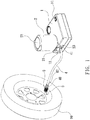
- an air compressor according to a preferred embodiment of the present invention comprises: a box 1, a sealant supply can 2, and a connection hose 4.
- the box 1 includes a button 11 fixed on a top thereof, a coupling orifice 12 defined on a peripheral side thereof, and a body of the air compressor (not shown) accommodated in the box 1.
- the connection hose 4 includes a first segment 41 formed on a first end thereof, and the connection hose 4 includes a second segment 42 formed on a second end thereof and having an anti-spray connector 5 connected on the second segment 42.
- the sealant supply can 2 is connected on the coupling orifice 12, and the tire sealant supply can 2 includes an open segment 21 extending downward, a bottom fringe 22 extending upward, and a supply tube 23 configured to engage with the first segment 41 of the connection hose 4.
- the anti-spray connector 5 of the second segment 42 of the connection hose 4 is screwed with an air nozzle 9 of a tire 99, when feeding chemical sealant and inflating compressed airs to the tire 99 which is broken.
- the compressed airs of the air compressor force the chemical sealant of the sealant supply can 2 to flow into the tire 99 via the connection hose 4, thus repairing and inflating the tire 99.
- the tire 99 is any one of an automobile tire, a motorcycle tire, and a bicycle tire.
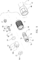
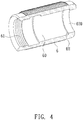
- an anti-spray joint structure for a connection of an air nozzle of the tire and the connection hose of the air compressor is applied to avoid eruption of the chemical sealant, and the anti-spray joint structure comprises: the anti-spray connector 5 connected on the second segment 42 of the connection hose 4, the anti-spray connector 5 includes a fitting sleeve 6 (as shown in FIG.
- the fitting sleeve 6 has a chamber 60 defined therein, a first threaded orifice 61 formed in a first end thereof and having female threads, a through orifice 620 defined on a second end of the fitting sleeve 6, a projected shoulder 62 formed on an inner wall of the chamber 60 proximate to the through orifice 620, and a diameter of the projected shoulder 62 is more than a diameter of the through orifice 620, wherein the first threaded orifice 61, the chamber 60, and the through orifice 620 are communicated with one another.
- a cylindrical base 7 (as shown in FIG.
- a cylindrical room 70 includes a cylindrical room 70, male threads 71 formed on an outer wall of a first end of the cylindrical base 7, a stepped coupling segment 72 extending on an outer wall of a second end of the cylindrical base 7, and a conduit 73 defined in the coupling segment 72 and communicating with the cylindrical room 70, wherein a diameter of the cylindrical room 70 is more than a diameter of the conduit 73, and the cylindrical base 7 further includes a first stepped portion 74 formed between the cylindrical room 70 and the conduit 73, a recessed section 75 formed proximate to the coupling segment 72, wherein a diameter of the cylindrical base 7 is more than a diameter of the recessed section 75, and a second stepped portion 76 is defined between the cylindrical base 7 and the recessed section 75.
- the coupling segment 72 of the cylindrical base 7 is put into the chamber 60 from the first threaded orifice 61 of the fitting sleeve 6 via the through orifice 620, such that the projected shoulder 62 contacts with the second stepped portion 76 of the cylindrical base 7, the coupling segment 72 of the cylindrical base 7 extends out of the fitting sleeve 6 to connect with the second segment 42 of the connection hose 4, and a fixing bushing 40 is configured to connect the connection hose 4 and the anti-spray connector 5, as illustrated in FIG. 3 .
- a first spring 51 is received into the cylindrical room 70 of the cylindrical base 7 so that a first end of the first spring 51 abuts against the first stepped portion 74;
- a valve bolt 8 (as shown in FIG. 6 ) includes a post 81 extending on a first end thereof, a connecting disc 82 extending from a second end of the valve bolt 8, multiple recesses 83 formed around an outer wall of the connecting disc 82, a neck 84 formed between the post 81 and the connecting disc 82, multiple spaced slots 85 defined around the post 81, and a first seal ring 86 fitted on the neck 84 of the valve bolt 8, such that the second end of the valve bolt 8 is put into the cylindrical room 70 of the cylindrical base 7 to contact with a second end of the first spring 51, as illustrated in FIG.
- a second seal ring 53 is fitted onto the male threads 71 of the cylindrical base 7;
- a lock element 52 (as shown in FIG. 7 ) includes at least one tangent plane 524 formed on an outer wall thereof, a stem 521 extending from a first end of the lock element 52 adjacent to the at least one tangent plane 524, a hollow cavity 520 defined in the lock element 52 and the stem 521, and a second threaded orifice 522 formed on a second end of the lock element 52 and having female threads, wherein a diameter of the second threaded orifice 522 is more than a diameter of the hollow cavity 520, and a third stepped portion 523 is defined between the second threaded orifice 522 and the hollow cavity 520; the lock element 52 is connected with the cylindrical base 7 which is coupled with the second seal ring 53, the first seal ring 86, and the first spring 51 so that the female threads of the second threaded orifice 522 are screwed with the male threads 71
- the multiple spaced slots 85 of the valve bolt 8 passes through the hollow cavity 520 of the lock element 52 and the passing orifice 540 of the abutting loop 54 to locate in the first threaded orifice 61, hence the first spring 51 forces the first seal ring 86 of the valve bolt 8 to contact with the connection portion of the third stepped portion 523 and the hollow cavity 520 matingly.
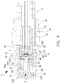
- a valve core assembly 91 is accommodated in the air nozzle 9 of the tire 99, and the valve core assembly 91 includes a mounting 92, an arcuate stop shoulder 921 surrounding around a mouth of the mounting 92 and extending inward from an end of the mounting 92, and an aperture 922 defined in the mounting 92; a hollow receiving sleeve 93 having a retaining shoulder 931 formed on a first end of the hollow receiving sleeve 93, and a holder 932 formed on a second end of the hollow receiving sleeve 93; a central needle 94 formed in a column shape and having multiple spaced ribs 941 formed on the central needle 94; a second spring 95 fitted with the central needle 94 and a first end of the second spring 95 abutting against the multiple spaced ribs 941 of the central needle 94; the central needle 94 being received in the hollow receiving sleeve 93 from the first end of the hollow receiving slee
- valve bolt 8 of the anti-spray connector 5 contacts with and urges the central needle 94 of the air nozzle 9 of the tire 99 to move so that the contacting loop 96 of the central needle 94 removes from the holder 932 of the hollow receiving sleeve 93 (as shown in FIG. 10 ).
- the valve bolt 8 When the first threaded orifice 61 of the anti-spray connector 5 is screwed with the air nozzle 9 of the tire 99, the valve bolt 8 is urged by the central needle 94 of the air nozzle 9 to press the first spring 51 so that the first seal ring 86 detaches from the connection portion of the third stepped portion 523 and the hollow cavity 520, and the hollow cavity 520 of the lock element 52 is communicated, in the meantime, the chemical sealant is pushed by the compressed airs to flow into the tire 99 via the conduit 73 of the cylindrical base 7, the cylindrical room 70 of the cylindrical base 7, the multiple recesses 83 of the connecting disc 82 of the valve bolt 8, the multiple spaced slots 85 of the valve bolt 8, the passing orifice 540 of the abutting loop 54, the first threaded orifice 61, the aperture 922 of the mounting 92 of the air nozzle 9, the hollow receiving sleeve 93, and the holder 932 of the hollow receiving sleeve 93, thus feeding the
- the anti-spray joint structure for the connection of the air nozzle of the tire and the connection hose of the air compressor is capable of avoiding the eruption of the chemical sealant in an incorrect operation.
Abstract
Description
- The present invention relates to an anti-spray joint structure for a connection of an air nozzle of a tire and a connection hose of an air compressor which is capable of avoiding counterflow and eruption of chemical sealant.
- A conventional air nozzle of a tire of a vehicle is applied to inflate or discharge airs into or from the tire. Furthermore, a conventional tire repair device is employed to feed chemical sealant and to inflate airs into the tire which is broken. The tire repair device is connected with an air compressor, and a sealant supply can is connected with an outlet valve of the air compressor, wherein compressed airs are controlled by a control valve to output the chemical sealant out of a connector on a distal end of a connection hose with the compressed airs. However, when a connection structure of the connector of the connection hose and the air core of the tire is not operated properly, the chemical sealant erupts out of the connector of the connection hose easily.
- The present invention has arisen to mitigate and/or obviate the afore-described disadvantages.
- The primary aspect of the present invention is to provide an anti-spray joint structure for a connection of an air nozzle of a tire and a connection hose of an air compressor which is capable of feeding chemical sealant and inflating compressed airs into a tire after the tire is broken.
- Another aspect of the present invention is to provide an anti-spray joint structure for a connection of an air nozzle of a tire and a connection hose of an air compressor which is capable of avoiding counterflow and eruption of chemical sealant.
-
-
FIG. 1 is a perspective view showing the application of an anti-spray joint structure for a connection of an air nozzle of a tire and a connection hose of an air compressor according to a preferred embodiment of the present invention. -
FIG. 2 is a perspective view showing the exploded components of the anti-spray joint structure according to the preferred embodiment of the present invention. -
FIG. 3 is a cross-sectional perspective view showing the assembly of the anti-spray joint structure according to the preferred embodiment of the present invention. -
FIG. 4 is a cross-sectional perspective view showing the assembly of a fitting sleeve of the anti-spray joint structure according to the preferred embodiment of the present invention. -
FIG. 5 is a cross-sectional perspective view showing the assembly of a cylindrical base of the anti-spray joint structure according to the preferred embodiment of the present invention. -
FIG. 6 is a perspective view showing the assembly of a valve bolt of the anti-spray joint structure according to the preferred embodiment of the present invention. -
FIG. 7 is a cross-sectional perspective view showing the assembly of a lock element of the anti-spray joint structure according to the preferred embodiment of the present invention. -
FIG. 8 is a cross sectional view showing the assembly of the anti-spray joint structure and the connection hose according to the preferred embodiment of the present invention. -
FIG. 9 is a cross sectional view showing the operation of the anti-spray joint structure according to the preferred embodiment of the present invention. -
FIG. 10 is a cross-sectional perspective view showing the assembly of a valve core assembly of the air nozzle of the tire according to the preferred embodiment of the present invention. - With reference to
FIGS. 1-3 , an air compressor according to a preferred embodiment of the present invention comprises: abox 1, a sealant supply can 2, and aconnection hose 4. - The
box 1 includes abutton 11 fixed on a top thereof, acoupling orifice 12 defined on a peripheral side thereof, and a body of the air compressor (not shown) accommodated in thebox 1. Theconnection hose 4 includes afirst segment 41 formed on a first end thereof, and theconnection hose 4 includes asecond segment 42 formed on a second end thereof and having ananti-spray connector 5 connected on thesecond segment 42. The sealant supply can 2 is connected on thecoupling orifice 12, and the tire sealant supply can 2 includes anopen segment 21 extending downward, abottom fringe 22 extending upward, and asupply tube 23 configured to engage with thefirst segment 41 of theconnection hose 4. Theanti-spray connector 5 of thesecond segment 42 of theconnection hose 4 is screwed with anair nozzle 9 of atire 99, when feeding chemical sealant and inflating compressed airs to thetire 99 which is broken. After thebox 1 is started by a vehicle power supply or other DC power supplies, the compressed airs of the air compressor force the chemical sealant of the sealant supply can 2 to flow into thetire 99 via theconnection hose 4, thus repairing and inflating thetire 99. Thetire 99 is any one of an automobile tire, a motorcycle tire, and a bicycle tire. - Referring to
FIGS. 2-8 , an anti-spray joint structure for a connection of an air nozzle of the tire and the connection hose of the air compressor is applied to avoid eruption of the chemical sealant, and the anti-spray joint structure comprises: theanti-spray connector 5 connected on thesecond segment 42 of theconnection hose 4, theanti-spray connector 5 includes a fitting sleeve 6 (as shown inFIG. 4 ) formed in a cylinder shape, and thefitting sleeve 6 has achamber 60 defined therein, a first threadedorifice 61 formed in a first end thereof and having female threads, athrough orifice 620 defined on a second end of thefitting sleeve 6, a projectedshoulder 62 formed on an inner wall of thechamber 60 proximate to thethrough orifice 620, and a diameter of the projectedshoulder 62 is more than a diameter of thethrough orifice 620, wherein the first threadedorifice 61, thechamber 60, and the throughorifice 620 are communicated with one another. A cylindrical base 7 (as shown inFIG. 5 ) includes acylindrical room 70,male threads 71 formed on an outer wall of a first end of thecylindrical base 7, astepped coupling segment 72 extending on an outer wall of a second end of thecylindrical base 7, and aconduit 73 defined in thecoupling segment 72 and communicating with thecylindrical room 70, wherein a diameter of thecylindrical room 70 is more than a diameter of theconduit 73, and thecylindrical base 7 further includes a firststepped portion 74 formed between thecylindrical room 70 and theconduit 73, arecessed section 75 formed proximate to thecoupling segment 72, wherein a diameter of thecylindrical base 7 is more than a diameter of therecessed section 75, and a secondstepped portion 76 is defined between thecylindrical base 7 and therecessed section 75. - The
coupling segment 72 of thecylindrical base 7 is put into thechamber 60 from the first threadedorifice 61 of thefitting sleeve 6 via the throughorifice 620, such that the projectedshoulder 62 contacts with the secondstepped portion 76 of thecylindrical base 7, thecoupling segment 72 of thecylindrical base 7 extends out of thefitting sleeve 6 to connect with thesecond segment 42 of theconnection hose 4, and afixing bushing 40 is configured to connect theconnection hose 4 and theanti-spray connector 5, as illustrated inFIG. 3 . - A
first spring 51 is received into thecylindrical room 70 of thecylindrical base 7 so that a first end of thefirst spring 51 abuts against the firststepped portion 74; a valve bolt 8 (as shown inFIG. 6 ) includes apost 81 extending on a first end thereof, a connectingdisc 82 extending from a second end of thevalve bolt 8,multiple recesses 83 formed around an outer wall of the connectingdisc 82, aneck 84 formed between thepost 81 and the connectingdisc 82, multiplespaced slots 85 defined around thepost 81, and afirst seal ring 86 fitted on theneck 84 of thevalve bolt 8, such that the second end of thevalve bolt 8 is put into thecylindrical room 70 of thecylindrical base 7 to contact with a second end of thefirst spring 51, as illustrated inFIG. 3 ; asecond seal ring 53 is fitted onto themale threads 71 of thecylindrical base 7; a lock element 52 (as shown inFIG. 7 ) includes at least onetangent plane 524 formed on an outer wall thereof, astem 521 extending from a first end of thelock element 52 adjacent to the at least onetangent plane 524, ahollow cavity 520 defined in thelock element 52 and thestem 521, and a second threadedorifice 522 formed on a second end of thelock element 52 and having female threads, wherein a diameter of the second threadedorifice 522 is more than a diameter of thehollow cavity 520, and a thirdstepped portion 523 is defined between the second threadedorifice 522 and thehollow cavity 520; thelock element 52 is connected with thecylindrical base 7 which is coupled with thesecond seal ring 53, thefirst seal ring 86, and thefirst spring 51 so that the female threads of the second threadedorifice 522 are screwed with themale threads 71 of thecylindrical base 7, thecylindrical base 7 abuts against the thirdstepped portion 523 of thelock element 52, and thefirst spring 51 pushes thevalve bolt 8 so that thefirst seal ring 86 of thevalve bolt 8 contacts with a connection portion of the third steppedportion 523 and thehollow cavity 520; anabutting loop 54 has a passing orifice 540 (as illustrated inFIG. 2 ) and is put into the first threadedorifice 61 of thefitting sleeve 6 to fit on thestem 521 and to abut against thelock element 52, as shown inFIG. 3 . The multiple spacedslots 85 of thevalve bolt 8 passes through thehollow cavity 520 of thelock element 52 and thepassing orifice 540 of theabutting loop 54 to locate in the first threadedorifice 61, hence thefirst spring 51 forces thefirst seal ring 86 of thevalve bolt 8 to contact with the connection portion of the third steppedportion 523 and thehollow cavity 520 matingly. - Referring to
FIG. 8 , after thebutton 11 of thebox 1 is turned on (as shown inFIG. 1 ), a pressure of the compressed airs of the air compressor forces the chemical sealant to flow, but the chemical sealant does not flow through thehollow cavity 520 of thelock element 52 because thefirst seal ring 86 of thevalve bolt 8 contacts with the connection portion of the third steppedportion 523 and thehollow cavity 520 tightly, thus avoiding the eruption of the chemical sealant. - As shown in
FIGS. 9 and10 , avalve core assembly 91 is accommodated in theair nozzle 9 of thetire 99, and thevalve core assembly 91 includes amounting 92, anarcuate stop shoulder 921 surrounding around a mouth of themounting 92 and extending inward from an end of themounting 92, and anaperture 922 defined in themounting 92; a hollowreceiving sleeve 93 having a retainingshoulder 931 formed on a first end of the hollow receivingsleeve 93, and aholder 932 formed on a second end of the hollow receivingsleeve 93; acentral needle 94 formed in a column shape and having multiple spacedribs 941 formed on thecentral needle 94; asecond spring 95 fitted with thecentral needle 94 and a first end of thesecond spring 95 abutting against the multiple spacedribs 941 of thecentral needle 94; thecentral needle 94 being received in the hollow receivingsleeve 93 from the first end of the hollow receivingsleeve 93 so that a second end of thesecond spring 95 contacts with theholder 932, and thesecond spring 95 is surrounded by the receivinghollow sleeve 93; a contactingloop 96 fitted on a first end of thecentral needle 94; wherein after the hollow receivingsleeve 93 is connected with themounting 92, thearcuate stop shoulder 921 of themounting 92 engages with the retainingshoulder 931 of the hollow receivingsleeve 93, a second end of thecentral needle 94 extends out of theaperture 922 of themounting 92, and thesecond spring 95 pushes the contactingloop 96 of thecentral needle 94 to close theholder 932 of thehollow receiving sleeve 93. - As illustrated in
FIGS. 1 and9 , when the first threadedorifice 61 of theanti-spray connector 5 is screwed with theair nozzle 9 of thetire 99, thevalve bolt 8 of theanti-spray connector 5 contacts with and urges thecentral needle 94 of theair nozzle 9 of thetire 99 to move so that the contactingloop 96 of thecentral needle 94 removes from theholder 932 of the hollow receiving sleeve 93 (as shown inFIG. 10 ). When the first threadedorifice 61 of theanti-spray connector 5 is screwed with theair nozzle 9 of thetire 99, thevalve bolt 8 is urged by thecentral needle 94 of theair nozzle 9 to press thefirst spring 51 so that thefirst seal ring 86 detaches from the connection portion of the third steppedportion 523 and thehollow cavity 520, and thehollow cavity 520 of thelock element 52 is communicated, in the meantime, the chemical sealant is pushed by the compressed airs to flow into thetire 99 via theconduit 73 of thecylindrical base 7, thecylindrical room 70 of thecylindrical base 7, themultiple recesses 83 of the connectingdisc 82 of thevalve bolt 8, the multiple spacedslots 85 of thevalve bolt 8, thepassing orifice 540 of theabutting loop 54, the first threadedorifice 61, theaperture 922 of themounting 92 of theair nozzle 9, the hollow receivingsleeve 93, and theholder 932 of the hollow receivingsleeve 93, thus feeding the chemical sealant and inflating the compressed airs to thetire 99. - Thereby, the anti-spray joint structure for the connection of the air nozzle of the tire and the connection hose of the air compressor is capable of avoiding the eruption of the chemical sealant in an incorrect operation.
Claims (7)
- An anti-spray joint structure for a connection of an air nozzle (9) of a tire (99) and a connection hose (4) of an air compressor, the air compressor comprising:a box (1) including a body of the air compressor accommodated in the box (1) and started by a power supply;a sealant supply can (2) including an open segment (21) extending downward and configured to accommodate chemical sealant for repairing the tire (99) which is broken, and the sealant supply can (2) including a supply tube (23);a connection hose (4) including a first segment (41) formed on a first end of the connection hose (4), and the connection hose (4) including a second segment (42) formed on a second end the connection hose (4), the first segment (41) being connected with the supply tube (23) of the sealant supply can (2), and the second segment (42) being connected with the air nozzle (9) of the tire (99);characterized in that:a second segment (42) has an anti-spray connector (5) connected thereon, and the anti-spray connector (5) includes a fitting sleeve (6), wherein the fitting sleeve (6) has a threaded orifice (61) formed in a first end thereof and having female threads, a through orifice (620) defined on a second end of the fitting sleeve (6), and a projected shoulder (62) formed on an inner wall of the through orifice (620), wherein a diameter of the projected shoulder (62) is more than a diameter of the through orifice (620), and the threaded orifice (61) is communicated with the through orifice (620);a cylindrical base (7) includes a cylindrical room (70), a stepped coupling segment (72) extending on an outer wall of a second end of the cylindrical base (7), and a conduit (73) defined in the coupling segment (72) and communicating with the cylindrical room (70), wherein a diameter of the cylindrical room (70) is more than a diameter of the conduit (73), and the cylindrical base (7) further includes a first stepped portion (74) formed between the cylindrical room (70) and the conduit (73);a first spring (51) is received into the cylindrical room (70) of the cylindrical base (7) so that a first end of the first spring (51) abuts against first stepped portion (74);a valve bolt (8) includes a post (81) extending on a first end thereof, a connecting disc (82) extending from a second end of the valve bolt (8), and multiple spaced slots (85) defined around the post (81);a first seal ring (86) is fitted on the valve bolt (8);the second end of the valve bolt (8) is put into the cylindrical room (70) of the cylindrical base (7) to contact with a second end of the first spring (51);a lock element (52) includes at least one tangent plane (524) formed on an outer wall thereof, a stem (521) extending from a first end of the lock element (52) adjacent to the at least one tangent plane (524), and a hollow cavity (520) defined in the lock element (52) and the stem (521); andthe multiple spaced slots (85) of the valve bolt (8) passes through the hollow cavity (520) of the lock element (52) to locate in the threaded orifice (61), hence the first spring (51) forces the first seal ring (86) of the valve bolt (8) to contact with a connection portion of the third stepped portion (523) and the hollow cavity (520) matingly.
- The anti-spray joint structure as claimed in claim 1, characterized in that the fitting sleeve (6) has a chamber (60) defined therein, and the threaded orifice (61), the chamber (60), and the through orifice (620) are communicated with one another; the cylindrical base (7) further includes male threads (71) formed on an outer wall of a first end thereof, a recessed section (75) formed proximate to the coupling segment (72), wherein a diameter of the cylindrical base (7) is more than a diameter of the recessed section (75), and a second stepped portion (76) is defined between the cylindrical base (7) and the recessed section (75); the coupling segment (72) of the cylindrical base (7) is put into the chamber (60) from the threaded orifice (61) of the fitting sleeve (6) via the through orifice (620), such that the projected shoulder (62) contacts with the second stepped portion (76) of the cylindrical base (7).
- The anti-spray joint structure as claimed in claim 2, characterized in that the valve bolt (8) further includes multiple recesses (83) formed around an outer wall of the connecting disc (82), a neck (84) formed between the post (81) and the connecting disc (82), and the first seal ring (86) fitted on the neck (84) of the valve bolt (8).
- The anti-spray joint structure as claimed in claim 3, characterized in that the lock element (52) further includes a second threaded orifice (522) formed on a second end thereof and having female threads, wherein a diameter of the second threaded orifice (522) is more than a diameter of the hollow cavity (520), and a third stepped portion (523) is defined between the second threaded orifice (522) and the hollow cavity (520); a second seal ring (53) is fitted onto the male threads (71) of the cylindrical base (7); the lock element (52) is connected with the cylindrical base (7) which is coupled with the second seal ring (53), the first seal ring (86), and the first spring (51) so that the female threads of the second threaded orifice (522) are screwed with the male threads (71) of the cylindrical base (7), the cylindrical base (7) abuts against the third stepped portion (523) of the lock element (52), and the first spring (51) pushes the valve bolt (8) so that the first seal ring (86) of the valve bolt (8) contacts with the connection portion of the third stepped portion (523) and the hollow cavity (520).
- The anti-spray joint structure as claimed in claim 4, characterized in that an abutting loop (54) has a passing orifice (540) and is put into the first threaded orifice (61) of the fitting sleeve (6) to fit on the stem (521) and to abut against the lock element (52).
- The anti-spray joint structure as claimed in claim 2, characterized in that the coupling segment (72) of the cylindrical base (7) extends out of the fitting sleeve (6) to connect with the second segment (42) of the connection hose (4), and a fixing bushing (40) is configured to connect the connection hose (4) and the anti-spray connector (5).
- The anti-spray joint structure as claimed in claim 1, characterized in that a valve core assembly (91) is accommodated in the air nozzle (9) of the tire (99), and the valve core assembly (91) includes a mounting (92), an arcuate stop shoulder (921) surrounding around a mouth of the mounting (92) and extending inward from an end of the mounting (92), and an aperture (922) defined in the mounting (92); a hollow receiving sleeve (93) having a retaining shoulder (931) formed on a first end of the hollow receiving sleeve (93), and a holder (932) formed on a second end of the hollow receiving sleeve (93); a central needle (94) formed in a column shape and having multiple spaced ribs (941) formed on the central needle (94); a second spring (95) fitted with the central needle (94) and a first end of the second spring (95) abutting against the multiple spaced ribs (941) of the central needle (94); the central needle (94) being received in the hollow receiving sleeve (93) from the first end of the hollow receiving sleeve (93) so that a second end of the second spring (95) contacts with the holder (932), and the second spring (95) is surrounded by the receiving hollow sleeve (93); a contacting loop (96) fitted on a first end of the central needle (94); such that after the hollow receiving sleeve (93) is connected with the mounting (92), the arcuate stop shoulder (921) of the mounting (92) engages with the retaining shoulder (931) of the hollow receiving sleeve (93), a second end of the central needle (94) extends out of the aperture (922) of the mounting (92), and the second spring (95) pushes the contacting loop (96) of the central needle (94) to close the holder (932) of the hollow receiving sleeve (93).
Applications Claiming Priority (1)
| Application Number | Priority Date | Filing Date | Title |
|---|---|---|---|
| TW108133136A TWI732292B (en) | 2019-09-12 | 2019-09-12 | Anti-spray joint structure for tire and connection hose of vehicle air compressor |
Publications (2)
| Publication Number | Publication Date |
|---|---|
| EP3797977A1 true EP3797977A1 (en) | 2021-03-31 |
| EP3797977B1 EP3797977B1 (en) | 2024-01-17 |
Family
ID=72521371
Family Applications (1)
| Application Number | Title | Priority Date | Filing Date |
|---|---|---|---|
| EP20194929.4A Active EP3797977B1 (en) | 2019-09-12 | 2020-09-07 | Anti-spray joint structure for connection of air nozzle of tire and connection hose of air compressor |
Country Status (7)
| Country | Link |
|---|---|
| US (1) | US11046129B2 (en) |
| EP (1) | EP3797977B1 (en) |
| JP (2) | JP3229645U (en) |
| KR (1) | KR102347577B1 (en) |
| CN (2) | CN112483362B (en) |
| DE (1) | DE202020105136U1 (en) |
| TW (1) | TWI732292B (en) |
Families Citing this family (5)
| Publication number | Priority date | Publication date | Assignee | Title |
|---|---|---|---|---|
| TWM601302U (en) * | 2019-09-04 | 2020-09-11 | 周文三 | Blowout prevention joint structure of serially connected hose of air compressor for vehicle |
| TWI732292B (en) * | 2019-09-12 | 2021-07-01 | 周文三 | Anti-spray joint structure for tire and connection hose of vehicle air compressor |
| US11794426B2 (en) * | 2021-06-30 | 2023-10-24 | Illinois Tool Works Inc. | Flat tire repair device |
| CN114084314A (en) * | 2021-11-23 | 2022-02-25 | 大连海事大学 | A aerify and connect for inflatable marine system of withdrawing |
| US11739854B2 (en) | 2022-01-07 | 2023-08-29 | Permobil, Inc. | Valve assembly for an air cushion |
Citations (6)
| Publication number | Priority date | Publication date | Assignee | Title |
|---|---|---|---|---|
| WO2007102066A2 (en) * | 2006-03-07 | 2007-09-13 | Tek Global S.R.L. | Automatic kit, with a selector valve, for repairing and inflating inflatable articles |
| EP2186628A1 (en) * | 2007-07-27 | 2010-05-19 | Bridgestone Corporation | Valve adaptor and sealing/pump-up device with the same |
| DE202012100671U1 (en) * | 2011-03-10 | 2012-06-26 | Wen-San Jhou | Device for sealing and inflating inflatable objects |
| DE202012103464U1 (en) * | 2011-11-02 | 2012-12-20 | Wen-San Jhou | From a vehicle entrained air compression device |
| DE202013101644U1 (en) * | 2012-04-27 | 2013-08-09 | Wen-San Jhou | From a vehicle entrained air compression device |
| DE202018107206U1 (en) * | 2017-12-25 | 2019-01-11 | Unik World Industrial Co., Ltd. | Design of a back-up fuse adapter for connection to a flexible connection hose of a vehicle-carried air compression device for repairing and filling damaged tires |
Family Cites Families (18)
| Publication number | Priority date | Publication date | Assignee | Title |
|---|---|---|---|---|
| TW581150U (en) * | 2003-03-26 | 2004-03-21 | Kurt Kemppainen | Inflating device |
| US20080190489A1 (en) * | 2007-02-13 | 2008-08-14 | Eqair, Llc | Chuck for tire inflation valve |
| WO2009119317A1 (en) * | 2008-03-25 | 2009-10-01 | 住友ゴム工業株式会社 | Tire puncture repair apparatus |
| DE102011001603A1 (en) * | 2010-11-15 | 2012-05-16 | Illinois Tool Works, Inc. | Device for dispensing tire sealant from a container |
| TWI482908B (en) * | 2011-03-07 | 2015-05-01 | Wen San Chou | Air compressor for vehicle |
| TWM453735U (en) * | 2012-11-06 | 2013-05-21 | Wen-San Chou | Joint structure of cascaded hose for vehicle-mounted air compressor |
| JP6302545B2 (en) * | 2013-11-28 | 2018-03-28 | 住友ゴム工業株式会社 | Device and self-closing threaded joint for sealing and / or expanding objects |
| US9193229B2 (en) * | 2013-12-03 | 2015-11-24 | Top Alliance Technology Limited | Tire repair device |
| TWI583572B (en) * | 2014-11-18 | 2017-05-21 | 周文三 | Emergency repair kit for tire punctures |
| TWM523766U (en) * | 2016-02-04 | 2016-06-11 | Shieun Ta Industry Co Ltd | Air nozzle |
| US20200368980A1 (en) * | 2017-08-03 | 2020-11-26 | Trydel Research Pty Ltd | Improvements to tire repair apparatus |
| US20190100062A1 (en) * | 2017-09-29 | 2019-04-04 | Mould Flying Industrial Co., Ltd. | Screw-in valve connector |
| US11292658B2 (en) * | 2017-10-23 | 2022-04-05 | Active Tools International (Hk) Ltd. | One-way valve, and tire repair sealant bottle having same |
| TWM572946U (en) * | 2017-12-25 | 2019-01-11 | 已久工業股份有限公司 | Check connector structure of connection hose for vehicle air compressor |
| CN208670171U (en) * | 2018-07-12 | 2019-03-29 | 上海华汇机电有限公司 | A kind of miniature one-way sealing gas nozzle |
| TWI709500B (en) * | 2019-05-30 | 2020-11-11 | 周文三 | Anti-jet joint structure of connection hose of vehicle air compressor |
| TWI732292B (en) | 2019-09-12 | 2021-07-01 | 周文三 | Anti-spray joint structure for tire and connection hose of vehicle air compressor |
| TWM600815U (en) * | 2019-09-12 | 2020-09-01 | 周文三 | Blowout prevention joint structure for connecting tire air nozzle and air compressor hose |
-
2019
- 2019-09-12 TW TW108133136A patent/TWI732292B/en active
-
2020
- 2020-08-26 KR KR1020200107771A patent/KR102347577B1/en active IP Right Grant
- 2020-09-02 US US17/010,639 patent/US11046129B2/en active Active
- 2020-09-02 CN CN202010909819.5A patent/CN112483362B/en active Active
- 2020-09-02 CN CN202021889639.7U patent/CN212774680U/en active Active
- 2020-09-06 DE DE202020105136.9U patent/DE202020105136U1/en active Active
- 2020-09-07 EP EP20194929.4A patent/EP3797977B1/en active Active
- 2020-09-11 JP JP2020003900U patent/JP3229645U/en active Active
- 2020-09-11 JP JP2020152556A patent/JP7073461B2/en active Active
Patent Citations (6)
| Publication number | Priority date | Publication date | Assignee | Title |
|---|---|---|---|---|
| WO2007102066A2 (en) * | 2006-03-07 | 2007-09-13 | Tek Global S.R.L. | Automatic kit, with a selector valve, for repairing and inflating inflatable articles |
| EP2186628A1 (en) * | 2007-07-27 | 2010-05-19 | Bridgestone Corporation | Valve adaptor and sealing/pump-up device with the same |
| DE202012100671U1 (en) * | 2011-03-10 | 2012-06-26 | Wen-San Jhou | Device for sealing and inflating inflatable objects |
| DE202012103464U1 (en) * | 2011-11-02 | 2012-12-20 | Wen-San Jhou | From a vehicle entrained air compression device |
| DE202013101644U1 (en) * | 2012-04-27 | 2013-08-09 | Wen-San Jhou | From a vehicle entrained air compression device |
| DE202018107206U1 (en) * | 2017-12-25 | 2019-01-11 | Unik World Industrial Co., Ltd. | Design of a back-up fuse adapter for connection to a flexible connection hose of a vehicle-carried air compression device for repairing and filling damaged tires |
Also Published As
| Publication number | Publication date |
|---|---|
| CN212774680U (en) | 2021-03-23 |
| EP3797977B1 (en) | 2024-01-17 |
| JP3229645U (en) | 2020-12-17 |
| US11046129B2 (en) | 2021-06-29 |
| CN112483362B (en) | 2022-07-22 |
| DE202020105136U1 (en) | 2020-09-24 |
| KR20210031818A (en) | 2021-03-23 |
| JP7073461B2 (en) | 2022-05-23 |
| JP2021041924A (en) | 2021-03-18 |
| KR102347577B1 (en) | 2022-01-05 |
| TWI732292B (en) | 2021-07-01 |
| TW202111239A (en) | 2021-03-16 |
| US20210080041A1 (en) | 2021-03-18 |
| CN112483362A (en) | 2021-03-12 |
Similar Documents
| Publication | Publication Date | Title |
|---|---|---|
| EP3797977A1 (en) | Anti-spray joint structure for connection of air nozzle of tire and connection hose of air compressor | |
| EP3797979A1 (en) | Check joint structure for connection of air nozzle of tire and connection hose of air compressor | |
| EP3797978A1 (en) | Anti-spray structure for connection of air nozzle of tire of vehicle and connection hose of air compressor | |
| US11052621B2 (en) | Combination structure for a hose connected between an air compressor and a tire | |
| EP2657008B1 (en) | Vehicle-carried air compressor device | |
| EP3756871A1 (en) | Anti-jet joint structure of connection hose of vehicle air compressor | |
| US8978716B2 (en) | Vehicle-carried air compression device | |
| US8402987B2 (en) | Schrader valve/Presta valve dual-mode valve cap | |
| US8342209B2 (en) | Plug for fluid-transfer coupling device | |
| US5902097A (en) | Pumping device with a clamping nozzle for various valves | |
| US20210016616A1 (en) | Air compressor capable of inflating air and supplying sealant | |
| EP3202601A1 (en) | Pneumatic valve adaptor | |
| EP3797976A1 (en) | Anti-spray joint structure of connection hose of vehicle air compressor | |
| EP3797981A1 (en) | Check structure for connection of air nozzle of tire and connection hose of air compressor | |
| EP3936349A1 (en) | Air pipe device of air compressor | |
| US20170009922A1 (en) | Quick Connector Structure for a Pneumatic Valve | |
| US11358351B2 (en) | Anti-spray joint structure of connection hose of vehicle air compressor | |
| EP3797980A1 (en) | Check joint structure for connection of air nozzle of tire and connector of connection hose of air compressor | |
| CN110486621B (en) | Gas-filled joint for gas cylinder | |
| US20200101487A1 (en) | Sealant dispenser | |
| EP2770207B1 (en) | Automatic-switch nozzle head having two valve mouths and single-mouth nozzle head | |
| KR100324547B1 (en) | one-touch type coupling | |
| CN109253071B (en) | Pressure relief joint used in cooperation with inflator | |
| KR200421703Y1 (en) | Spray Hose Connecting Structure |
Legal Events
| Date | Code | Title | Description |
|---|---|---|---|
| STAA | Information on the status of an ep patent application or granted ep patent |
Free format text: STATUS: UNKNOWN |
|
| PUAI | Public reference made under article 153(3) epc to a published international application that has entered the european phase |
Free format text: ORIGINAL CODE: 0009012 |
|
| STAA | Information on the status of an ep patent application or granted ep patent |
Free format text: STATUS: REQUEST FOR EXAMINATION WAS MADE |
|
| 17P | Request for examination filed |
Effective date: 20201210 |
|
| AK | Designated contracting states |
Kind code of ref document: A1 Designated state(s): AL AT BE BG CH CY CZ DE DK EE ES FI FR GB GR HR HU IE IS IT LI LT LU LV MC MK MT NL NO PL PT RO RS SE SI SK SM TR |
|
| AX | Request for extension of the european patent |
Extension state: BA ME |
|
| RIC1 | Information provided on ipc code assigned before grant |
Ipc: F16K 15/20 20060101ALI20231004BHEP Ipc: B60C 29/00 20060101ALI20231004BHEP Ipc: B29C 73/16 20060101AFI20231004BHEP |
|
| GRAP | Despatch of communication of intention to grant a patent |
Free format text: ORIGINAL CODE: EPIDOSNIGR1 |
|
| STAA | Information on the status of an ep patent application or granted ep patent |
Free format text: STATUS: GRANT OF PATENT IS INTENDED |
|
| GRAS | Grant fee paid |
Free format text: ORIGINAL CODE: EPIDOSNIGR3 |
|
| INTG | Intention to grant announced |
Effective date: 20231115 |
|
| GRAA | (expected) grant |
Free format text: ORIGINAL CODE: 0009210 |
|
| STAA | Information on the status of an ep patent application or granted ep patent |
Free format text: STATUS: THE PATENT HAS BEEN GRANTED |
|
| AK | Designated contracting states |
Kind code of ref document: B1 Designated state(s): AL AT BE BG CH CY CZ DE DK EE ES FI FR GB GR HR HU IE IS IT LI LT LU LV MC MK MT NL NO PL PT RO RS SE SI SK SM TR |
|
| REG | Reference to a national code |
Ref country code: GB Ref legal event code: FG4D |
|
| REG | Reference to a national code |
Ref country code: CH Ref legal event code: EP |
|
| REG | Reference to a national code |
Ref country code: DE Ref legal event code: R096 Ref document number: 602020024410 Country of ref document: DE |
|
| REG | Reference to a national code |
Ref country code: IE Ref legal event code: FG4D |